1
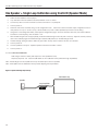
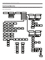
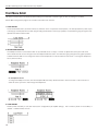
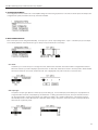
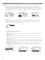
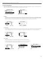
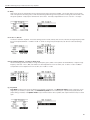
PLA DL210NET
Digi-Loop™ DSP Induction Loop Amplifier
USER Manual
MAN 179C
PLA DL210NET Digi-Loop™ DSP Induction Loop Amplifier
Table of Contents
Safety Warnings and Instructions 4
System Overview 6
Controls and Connectors 7
Figure A: Front Panel 7
Figure B: Rear Panel 7
Typical Connections 8
Figure C: Example Connections 8
Rack Installation 9
Figure D: RS-232 Standard Cable Pinout Configuration 9
Setup and Calibration Procedure (using a laptop or windows tablet) 10
Single Perimeter Loop Configuration using front LCD (Dual Loop Mode) 11
Figure E: Single Loop Concept 11
Dual Loop Calibration using front LCD (Dual Loop Mode) 12
Figure F: Dual-Loop Concept 12
Phased-Array Calibration using front LCD (Phased Array Mode) 13
Figure G: Phased-Array Concept 13
One Speaker + Single Loop Calibration using front LCD (Speaker Mode) 14
Figure H: Speaker and Single Loop Concept 14
Front Screen Menu Tree 15
Figure I: Front Screen Menu Tree 15
Front Menu Detail 16
1. LOOP STATUS ������������������������������������������������������������������������������������������������������������������������������������������������������������������������������ 16
2. HEADPHONE MONITOR ��������������������������������������������������������������������������������������������������������������������������������������������������������������� 16
2a. Headphone Source �������������������������������������������������������������������������������������������������������������������������������������������������������������� 16
3. LOAD PRESET ������������������������������������������������������������������������������������������������������������������������������������������������������������������������������ 16
4. CONFIGURATION MENU �������������������������������������������������������������������������������������������������������������������������������������������������������������� 17
5. INPUT CONFIGURATION ������������������������������������������������������������������������������������������������������������������������������������������������������������� 17
5a1. Name ��������������������������������������������������������������������������������������������������������������������������������������������������������������������������������� 17
5a2. Input Type �������������������������������������������������������������������������������������������������������������������������������������������������������������������������� 17
5a3. EQ ������������������������������������������������������������������������������������������������������������������������������������������������������������������������������������� 18
5a4. Compression ���������������������������������������������������������������������������������������������������������������������������������������������������������������������� 18
5a4a-e. Threshold, Ratio, Attack, Release, Makeup ������������������������������������������������������������������������������������������������������������������� 18
6. OUTPUT CONFIGURATION ��������������������������������������������������������������������������������������������������������������������������������������������������������� 19
6a. Name ����������������������������������������������������������������������������������������������������������������������������������������������������������������������������������� 19
6b. Input Mixer ��������������������������������������������������������������������������������������������������������������������������������������������������������������������������� 19
2
PLA DL210NET Digi-Loop™ DSP Induction Loop Amplifier
6c1-2. Filters ������������������������������������������������������������������������������������������������������������������������������������������������������������������������������ 19
6d. AGC ������������������������������������������������������������������������������������������������������������������������������������������������������������������������������������ 20
6d1-6. AGC Level, Hold Time, Attack, Release �������������������������������������������������������������������������������������������������������������������������� 20
6e. Delay ������������������������������������������������������������������������������������������������������������������������������������������������������������������������������������ 21
6f1-3. EQ - Lo, Mid, Hi ��������������������������������������������������������������������������������������������������������������������������������������������������������������� 21
6f4a-d. Advanced Settings - Lo, Mid, Hi, Metal Comp ���������������������������������������������������������������������������������������������������������������� 21
6g. Loop Mode �������������������������������������������������������������������������������������������������������������������������������������������������������������������������� 21
7. SYSTEM CONFIGURATION ���������������������������������������������������������������������������������������������������������������������������������������������������������� 22
7a1-3. Presets - Load Preset, Save Preset, Change Name �������������������������������������������������������������������������������������������������������� 22
7b. RS-232 �������������������������������������������������������������������������������������������������������������������������������������������������������������������������������� 22
7c. Network ������������������������������������������������������������������������������������������������������������������������������������������������������������������������������� 23
7d1-3. LCD - Backlight, Delay, Brightness ���������������������������������������������������������������������������������������������������������������������������������� 23
7e1-2. Security - Set Password, Password Timeout ������������������������������������������������������������������������������������������������������������������� 23
7f1-2. Power Save - Auto Sleep, Threshold �������������������������������������������������������������������������������������������������������������������������������� 23
7g. Tech Tools ���������������������������������������������������������������������������������������������������������������������������������������������������������������������������� 24
7g1a-c. Calibrate - Output, Frequency, Volume ������������������������������������������������������������������������������������������������������������������������� 24
7g2. Loop Test ��������������������������������������������������������������������������������������������������������������������������������������������������������������������������� 24
7g3. Version ������������������������������������������������������������������������������������������������������������������������������������������������������������������������������� 24
7g4. Device Name ��������������������������������������������������������������������������������������������������������������������������������������������������������������������� 25
7g5. IP Address ������������������������������������������������������������������������������������������������������������������������������������������������������������������������� 25
7g6. Amp Temp ������������������������������������������������������������������������������������������������������������������������������������������������������������������������� 25
7g7. Reset All ����������������������������������������������������������������������������������������������������������������������������������������������������������������������������� 25
PC Application Initial Setup 26
Figure J: Application Settings Window 26
Using the PC Mixer Application 27
Figure K: PC App Toolbar 27
Figure L: PC App Main Screen 28
Figure M: Input Effects 29
Figure N: Output Effects 30
Figure O: Amplifier Status Window 31
Figure P: Calibration Window (Phased-Array Mode shown) 31
Specifications 32
Troubleshooting 33
2-year Warranty 34
Notes 35
3
PLA DL210NET Digi-Loop™ DSP Induction Loop Amplifier
Safety Warnings and Instructions
WARNING! TO REDUCE THE RISK OF FIRE OR ELECTRIC SHOCK, DO NOT EXPOSE THIS APPLIANCE TO RAIN OR MOISTURE.
CAUTION!
TO REDUCE THE RISK OF ELECTRIC SHOCK, DO NOT REMOVE COVER. NO USER-SERVICEABLE PARTS INSIDE. REFER
SERVICING TO QUALIFIED SERVICE PERSONNEL.
This symbol on the amplifier
is intended to alert the user to the presence of un-insulated “dangerous voltage” within the
products enclosure that may be of sufficient magnitude to constitute a risk of electric shock to persons.
This symbol on the amplifier
is intended to alert the user to the presence of important operating and maintenance (servicing)
instructions in the literature accompanying the appliance.
POWER CORD NOTICE FOR INTERNATIONAL OPERATION - Please call Williams Sound Customer Service at 800.328.6190 to
order the appropriate power cord for the country of use.
Important Safety Instructions:
1. Read these instructions
2. Keep these instructions
3. Heed all warnings
4. Follow all instructions
5. Do not use this apparatus near water.
6. Clean only with dry cloth.
7. Do not block any ventilation openings. Install in accordance with the manufacturer’s instructions.
8. Do not install near any heat sources such as radiators, heat registers, stoves, or other apparatus (including amplifiers) that produce
heat.
9. Do not defeat the safety purpose of the polarized or grounding-type plug. A polarized plug has two blades with one wider than the
other. A grounding type plug has two blades and a third grounding prong. The wide blade or the third prong is provided for your
safety. If the provided plug does not fit into your outlet, consult an electrician for replacement of the obsolete outlet.
10. Protect the power cord from being walked on or pinched particularly at plugs, convenience receptacles, and the point where they
exit from the apparatus.
11. Only use attachments/accessories specified by the manufacturer.
12. Unplug this apparatus during lightning storms or when unused for long periods of time.
13. Refer all servicing to qualified service personnel. Servicing is required when the apparatus has been damaged in any way, such as
power-supply cord or plug is damaged, liquid has been spilled or objects have fallen into the apparatus, the apparatus has been
exposed to rain or moisture, does not operate normally, or has been dropped.
14. The apparatus shall not be exposed to dripping or splashing and that no objects filled with liquids, such as vases, shall be placed
on the apparatus.
15. Carts and Stands - The appliance should be used only with a cart or stand that is recommended by the manufacturer. An appliance
4
PLA DL210NET Digi-Loop™ DSP Induction Loop Amplifier
and cart combination should be moved with care. Quick stops, excessive force and uneven surfaces may cause the appliance and cart
combination to overturn.
16. Wall or ceiling Mounting - The appliance should be mounted to a wall or ceiling only as recommended by the manufacturer.
17. Power Sources - The appliance should be connected to a power supply only of the type described in the operating instructions or
as marked on the appliance.
18. Object and Liquid Entry - Care should be taken so that objects do not fall and liquids are not spilled into the enclosure through the
openings.
19. Servicing - The user should not attempt to service the appliance beyond that described in the operating instructions. All other
servicing should be referred to qualified service personnel.
Precautions:
1. Power – WARNING, BEFORE TURNING ON THE POWER FOR THE FIRST TIME, READ THE FOLLOWING SECTION
CAREFULLY. The amplifier is designed for use only with the line cord of the region in which it will be operated.
2. Voltage Label (Rear Panel) – A label located at the rear panel power connection indicates the AC power input for the unit. The label
will read 100-240V AC 50-60Hz 210W Auto-switching.
3. Do Not Plug in the input, output, ethernet, USB or RS-232 connections while the power switch is switched to the “ON” position.
4. Do Not Touch the PLA DL210NET with wet hands. Do not handle the PLA DL210NET or power cord when your hands are wet
or damp. If water or any other liquid enters the PLA DL210NET cabinet, take the PLA DL210NET to qualified service personnel for
inspection.
5. Place the PLA DL210NET in a well, ventilated location. Take special care to provide plenty of ventilation on all sides of the PLA
DL210NET especially when it is placed in an audio rack. If ventilation is blocked, the PLA DL210NET may over heat and malfunction.
Do not expose the PLA DL210NET to direct sun light or heating units as the PLA DL210NET internal components temperature may
rise and shorten the life of the components. Avoid damp and dusty places.
6. Care – From time to time you should wipe off the front and side panels and the cabinet with a soft cloth. Do not use rough material,
thinners, alcohol or other chemical solvents or cloths since this may damage the finish or remove the panel lettering.
5
PLA DL210NET Digi-Loop™ DSP Induction Loop Amplifier
System Overview
Thank you for purchasing the PLA DL210 Digi-Loop™ DSP Induction Loop Amplifier. This is the latest in induction loop technology.
An induction loop system uses a large copper loop, usually run on the floor around the inside perimeter of a room, to transmit
electromagnetic signals to a receiving device that picks up the broadcast. One advantage of loop systems over other systems is that
listeners with T-coil equipped devices (such as hearing aids or cochlear implants) can pick up the broadcast directly without any additional
equipment. Users without T-coil devices can use optional loop receivers with earphones or headphones to hear the broadcast. This system
helps large or small groups overcome background noise and distance to clearly hear the speaker.
The PLA DL210 features DSP Audio processing with an XLR Digital Input. The Class D amplifier delivers crisp, clear audio making speech
more intelligible to the listener. The system technician has control over Mixing, Equalization, Compression Ratio, Phase, and Frequencyshaping parameters. High-current output means good powerful broadcast and listener reception regardless of position in the room.
Features
• DSP Audio Processing
• Digital XLR Input
• LCD Screen with Metering
• Ethernet, RS-232, and USB control
• Mixing, Equalization, Compression, Phase, and Frequency-shaping
• Crystal-clear Class D amplification
• High output current: 12/10A
• Power-save mode
• Master Gain Control
• Active protection against short circuits
• Phoenix input configurable as microphone input or line input, balanced or unbalanced
• Loop-through Line Output
• Standard 2RU 19” Rack Mount
• Meets ADA / ADAAG Guidelines
• 2 year Warranty
AMPLIFIER APPLICATIONS
· Courtrooms
· House of Worship
· Hearing Assistance
· Conference Rooms
IMPORTANT NOTE ABOUT FRONT DISPLAY SCREEN CARE
The Front Display should be cleaned with a clean, damp microfiber cloth only. This will prolong the life and legibility of the screen. Do not
use Windex or any other type of cleaner or cloth/paper towel on the screen.
6
PLA DL210NET Digi-Loop™ DSP Induction Loop Amplifier
Controls and Connectors
Figure A: Front Panel
MENU (GUI)
DISPLAY
MENU
CONTROL
KNOB
MENU (GUI)
DISPLAY
MENU
CONTROL
KNOB
HEADPHONE JACK
ETHERNET
JACK
MIC/LINE
INPUTS
Figure B: Rear Panel
SPEAKER-LEVEL
INPUTS
COOLING FAN
HEADPHONE JACK
ETHERNET
JACK
AES/EBU
XLR JACK
RS-232
JACK
MIC/LINE
INPUTS
USB
JACK
SPEAKER-LEVEL
INPUTS
LINE INPUTS RCA
LINE
OUTPUTS
COOLING FAN
INDUCTION
LOOP/SPEAKER
OUTPUTS
POWER
AND
FUSE ACCESS
A432
AES/EBU
XLR JACK
RS-232
JACK
USB
JACK
LINE INPUTS RCA
LINE
OUTPUTS
INDUCTION
LOOP/SPEAKER
OUTPUTS
POWER
AND
FUSE ACCESS
A432
7
PLA DL210NET Digi-Loop™ DSP Induction Loop Amplifier
Typical Connections
Figure C: Example Connections
ROUTER
COMPUTER
(HARD-WIRED TO ROUTER)
iPAD, ANDROID TABLET,
OR PHONE WITH WI-FI
LAPTOP (FOR INITIAL CALIBRATION/CONFIGURATION)
PLA DL210NET PROFESSIONAL INDUCTION LOOP AMPLIFIER WITH DIGITAL SIGNAL PROCESSING
TO RECORDING
EQUIPMENT
FROM COMMERCIAL
SPEAKER SYSTEM
INDUCTION LOOP
#1
UNBALANCED AUDIO FROM CONSUMERGRADE PRODUCT SUCH AS CD PLAYER or
MP3 PLAYER
ANALOG AUDIO
FROM MIXER, PREAMP, ETC.
BI-DIRECTIONAL CONTROL/FEEDBACK
LEGACY THIRD-PARTY CONTROLLER
(AMX, CRESTRON, ETC.)
INDUCTION LOOP
#2
DIGITAL AUDIO
FROM MIXER, PREAMP, ETC.
8
A434
PLA DL210NET Digi-Loop™ DSP Induction Loop Amplifier
Rack Installation
1.
Install into a 19” rack using 10-32 rack screws.
2.
Leave 1U rack space above for ventilation.
3.
A surge protector or power conditioner is highly recommended.
4.
Use a grounded outlet.
5.
Connect all input/outputs before applying power.
6.
Plug in the power cord and turn on the unit.
USB Cable Wiring
A standard USB cable (USB Male A to Male B) can be used to connect a computer (such as a laptop) to the Loop Amplifier directly for initial
configuration. No drivers are necessary, simply plug-in a USB cable, open the PC App, specify USB connection, and the PC App can be
used to change settings on the amplifier. Note: Firmware upgrades can only be done through the USB connection.
Ethernet Cable Wiring
If connecting directly from a Computer to the Loop Amplifier, an Ethernet Crossover Cable must be used.
If connecting through a network, a standard ethernet cable must be used to connect the Amplifier to the network, and a standard ethernet
cable must be used to connect the Computer to the network.
If a third party controller will be used (Crestron, AMX, Extron, etc.), a standard ethernet cable can be used to connect the amplifier and
controller to the network.
Note: A standard ethernet cable is terminated with either T568A pinout on both ends, or T568B pinout on both ends. A crossover cable
has T568A pinout on one end, and T568B pinout on the other end. See the internet for more information on terminating ethernet cables.
RS-232 Cable Wiring
This is required if the third-party controller (Crestron, AMX, Extron, etc.) only has RS-232 control available (no ethernet).The diagram below
DATA CARRIER DETECT
1
is for making a custom RS-232 control cable. The6 only pins required
are
2, 3 and 5. Pins 2 and 3 are reversed from one end to the
DATA SET
READY
RECEIVE
DATA 2, and “transmit” on connector 1 is connected to “receive”
2
other - so that “receive” on connector 1 is connected to “transmit”
on connector
REQUEST
SEND
7
on connector 2. This circuit facilitates 2-way communication
between
theTOthird-party
controller (Crestron, AMX, Extron, etc.) and the PLA
TRANSMIT DATA
3
DL210. See Figure D.
CLEAR TO SEND
8
4
9
5
CHASSIS GROUND
Figure D: RS-232 Standard Cable Pinout Configuration
6
1
2
7
3
8
4
9
5
DATA CARRIER DETECT
DATA SET READY
RECEIVE DATA
REQUEST TO SEND
TRANSMIT DATA
CLEAR TO SEND
DATA TERMINAL READY
RING INDICATOR
SIGNAL GROUND
CHASSIS GROUND
DATA TERMINAL READY
RING INDICATOR
SIGNAL GROUND
6
1
1
6
2
2
7
7
3
3
8
8
4
4
9
9
5
5
CABLE SHEILD
DB-9 CONNECTOR 1
DB-9 CONNECTOR 2
A433
6
1
1
6
2
2
7
7
3
3
8
8
4
4
9
PLA DL210NET Digi-Loop™ DSP Induction Loop Amplifier
Setup and Calibration Procedure (using a laptop or windows tablet)
If one is already familiar with loop systems, these steps can be used to get the amplifier up and running fairly quickly. A Field Strength Meter
is required to perform this procedure. The PC App is compatible with Windows-based PC’s only (not MAC or Android).
1.
The DC resistance of the loop should be between 0.5 – 1.5 Ohms.
2.
Download and Install the PC Mixer App on the tablet/computer/laptop that will be used to configure the PLA DL210NET. To
download the App, go to www.williamssound.com/catalog/pla-dl210net and click on the “Downloads” tab. After installation an icon
will appear in the program directory.
3.
With the amplifier off, connect the computer to the PLA DL210NET with a standard USB cable.
4.
Open the PC Mixer App on the computer.
5.
In the PC App, under the Settings tab
“GetMixerState”.
6.
Power ON the PLA DL210NET. When the amplifier is done starting up, the VU meters will show on the LCD Display.
7.
Click on the amplifier symbol on the top left corner. It should turn green, indicating the computer is now connected to the amplifier.
The sliders and VU meters on the PC App should move when the amplifier connects to the computer, indicating that the computer
has pulled the current state information from the amplifier.
8.
In the PC App, choose the Loop Mode: Dual-Loop, Phased Array, or Speaker (lower right corner above the Output VU Meters.
Note that for a single loop, “Dual-Loop” mode should be selected.
9.
Connect Loop A and Loop B to corresponding outputs on the back of the PLA DL210NET. If using a single loop, connect it to
Loop A. If using a Phased Array, connect the Master loop to Loop A and the Slave loop to Loop B. If using a speaker, connect it to
the Loop A Output and the loop wire to Loop B.
10.
Run a loop test to make sure the amplifier sees the loop(s) correctly and that there are no breaks in the loop wire(s). The loop test is
the
on the top toolbar, set the “AmpConnection” to be “USB”, and set “ConnectAction” to
symbol on the top toolbar. Loop test results show up in the status area just below the Output VU Meters (bottom right).
11.
Calibrate the loop amplifier to the loop(s). To do this, open the calibrate window
12.
Start with Loop A. Make sure the frequency is set to 1kHz. With a field strength meter set appropriately, measure the field strength
in the center of the loop at about waist height. Adjust the Volume in the calibrate window until the field strength meter shows 0dB
(reference level). This should be 400mA/m.
13.
If calibrating Dual Loops, repeat step 12 for Loop B.
14.
If calibrating a Phased-Array, observe the “Average Current” level in the calibrate window for Loop A. Click on the Loop A
button to switch to Loop B in the Calibrate Window, and turn the offset up until the average current for Loop B matches what
you observed for Loop A. Click on the Loop B button to observe the current for both loops-they should be close. Go to step 16.
15.
If calibrating a loop in “speaker” mode, Loop B is the only output that can be calibrated. Make sure the frequency is set to 1kHz.
With a field strength meter set appropriately, measure the field strength in the center of the loop at about waist height. Adjust the
Volume in the calibrate window until the field strength meter shows 0dB (reference level) for Loop B. This should be 400mA/m.
16.
Best Practice Step A: Equalize the other frequencies as best you can to meet the level you have at 1kHz. To do this, run each test
frequency one at a time from the calibrate window beginning with 500Hz. Do not adjust the volume. With the Field Strength meter,
measure the field strength at each test frequency, and observe how many dB the signal strength is from 0dB. Write them down.
17.
Best Practice Step B: Open the Output Effects Window for the Loop Output being used. For the test frequencies in step 16, adjust
the Bass, Midrange, Treble or Metal Compensation by the values you wrote down in step 16 to compensate for low or high points in
the frequency response. The goal is to get the frequency response ±3dB from 0dB (1kHz reference), from 100 Hz to 5kHz to meet
the IEC 60118-4 Specification.
18.
In the Output Effects Window: If the loop will be used for speech, choose the “Voice” preset for the Automatic Gain Control. If a
source like music will be used, choose the “Music” preset. The Voice preset is designed for pauses in the audio, while the Music
preset is designed for more continuous audio sources. If more fine-tuning of the AGC is needed, the Custom Preset can be used to
obtain access to the Hold Time, Attack, and Release adjustments.
19.
Configure the input types; i.e. condenser vs electret mic, using the Trim and Line buttons. When this has been done, power OFF
the amplifier, connect the microphones and other inputs, and power the amplifier back ON.
20.
Reconnect the computer/amplifier by clicking on the amplifier symbol (top left). Now use the PC App to adjust the inputs as you
would a normal mixer. When set correctly, the overall output (bottom right VU meters) should pulse to around 0dB on average.
21.
Once all of these adjustments have been finalized, use a loop receiver such as the Williams Sound PLR BP1 or PLR SR1 to listen
to the loop(s). After this test is successful, have someone with a T-Coil equipped hearing-aid (or T-Coil equipped cochlear implant)
also listen to the loop(s). The audio should be clear and intelligible.
10
(toolbar). If using a speaker, skip to step 15.
PLA DL210NET Digi-Loop™ DSP Induction Loop Amplifier
Single Perimeter Loop Configuration using front LCD (Dual Loop Mode)
1.
Define the area needed for the loop layout.
2.
DC resistance of the loop and lead wire should be between .5 and 1.5 Ohms.
3.
Connect loop wire to the DL210 Phoenix connector and insert to Loop Output A.
4.
Connect all inputs to be used into the DL210.
5.
Turn the power on.
6.
Rotate the menu knob clockwise and go to the configuration menu. Push knob in (click) to enter and select output configuration.
Turn the rotary selector to Loop A. Scroll to set-up, click and select loop mode. Select dual loop and click to store setting.
7.
Going back to the Configuration Menu, select System Configuration page in the menu and select tech tools, then select calibrate.
Scroll down to the frequency, click and select 1 kHz.
8.
With the field strength meter set appropriately, measure the field strength at the mid-point of the loop. Adjust the volume (one step
down in the calibrate page) until the field strength measures 0dB (400m/A) in the center of the looped area.
9.
This field strength setting should be 3dB at any point within the loop area to meet the IEC 60118-4 standard.
10.
Back out of calibrate/system configuration menu. The input to the amplifier should now be adjusted to an acceptable input level.
To meet the IEC 60118 Standard:
Field strength: 400mA/m peak response at 1kHz (Calibration Point)
Frequency response: 100 - 5000Hz ±3dB relative to 1kHz Calibration Point (achieved through Equalization)
Note: The lead length from the amplifier to the loop should be kept as short as possible.
Note: The amplifier must be calibrated to the loop before adjusting the Output Effects.
Figure E: Single Loop Concept
Perimeter Loop
Loop Amplifier
Cancellation Loop
Main
Loop
Loop Amplifier
Cancellation
Loop
Loop
Limits overspill
in this direction
11
PLA DL210NET Digi-Loop™ DSP Induction Loop Amplifier
Dual Loop Calibration using front LCD (Dual Loop Mode)
Note: this mode is also used for a single loop; in this case steps referring to Loop B can be skipped.
1.
Define the areas needed for the loop layout.
2.
DC resistance for each separate loop with lead wire should be between .5 and 1.5 Ohms.
3.
Connect loop wire to the DL210 Phoenix connectors and connect to Loop Outputs A and B.
4.
Connect all inputs to be used into the DL210.
5.
Turn the power on.
6.
Rotate the menu knob clockwise and go to the configuration menu. Push knob to enter and select output configuration and turn
rotary selector to Loop A. Scroll to set-up, click and select loop mode. Select dual loop and click to store setting.
7.
Going back to the Configuration Menu, select System Configuration page in the menu and select tech tools, then select calibrate.
Scroll down to the frequency, click and select 1 kHz.
8.
With the field strength meter set appropriately, measure the field strength at the mid-point of the loop. Adjust the volume (one step
down in the calibrate page) until the field strength measures 0dB (400mA/m).
9.
Rotate the menu knob clockwise and go to the configuration menu. Push knob to enter and select output configuration and turn
rotary selector to Loop B. Scroll to set-up, click and select loop mode. Select dual loop and click to store setting.
10.
Going back to the Configuration Menu, select System Configuration page in the menu and select tech tools, then select calibrate.
Scroll down to the frequency, click and select 1 kHz.
11.
With the field strength meter set appropriately, measure the field strength at the mid-point of the loop. Adjust the volume (one step
down in the calibrate page) until the field strength measures 0dB (400mA/m) with a field strength meter.
12.
This field strength reading should be 3dB at any point within the loop area to meet the IEC 60118-4 standard.Perimeter Loop
To meet the IEC 60118 Standard:
Speaker
Loop Amplifier
Field strength: 400mA/m audio peak response at 1kHz (Calibration Point)
Frequency response: 100 - 5000Hz ±3dB relative to 1kHz Calibration Point (achieved through Equalization)
Note: The lead length from the amplifier to the loops should be kept as short as possible.
Note: The amplifier must be calibrated to the loops before adjusting the Output Effects.
Figure F: Dual-Loop Concept
Perimeter Loop
Perimeter Loop
Loop Amplifier
12
PLA DL210NET Digi-Loop™ DSP Induction Loop Amplifier
Phased-Array Calibration using front LCD (Phased Array Mode)
1.
Master and Slave loop wire layout should follow parameters defined by blueprints and site survey findings.
2.
Loop wire and lead wire DC resistance should be between .5 and 1.5 Ohms on both the Master and Slave loops.
3.
Connect the Master Loop wire to the DL210 Phoenix connector and connect to Loop Output A.
4.
Turn the power on, rotate the menu control clockwise and go to the configuration menu. Push the menu control to enter and select
output configuration and rotate menu control to Loop A. Scroll to set-up, click and select loop mode. Select Phased Array and
click to store setting.
5.
Access System Configuration/tech tools/calibrate screen. Set the frequency to 1kHz and set the output level to Loop Output A
until it meets 400mA/m (using the field strength meter) at the center of the looped area. The current in the Master (A) should be
measured and then duplicated for the slave loop (B).
6.
Connect the Slave Loop wire to the DL210 Phoenix connector and connect to Loop Output B. Adjust the current into Slave loop to
match the Master Loop.
7.
Turn the power off.
8.
Connect all inputs to be used into the DL210.
9.
Turn the power on.
10.
This field strength at 1kHz should be 3dB at any point within the loop area to meet the IEC 60118-4 standard.
To meet the IEC 60118 Standard:
Field strength: 400mA/m audio peak response at 1kHz (Calibration Point)
Frequency response: 100 - 5000Hz ±3dB relative to 1kHz Calibration Point (achieved through Equalization)
Note: The lead length from the amplifier to the loops should be kept as short as possible.
Note: The amplifier must be calibrated to the loops before adjusting the Output Effects.
Figure G: Phased-Array Concept
Phased Array (Low Overspill)
Master Loop
Slave Loop
Master Loop + Slave Loop = Phased Array
Loop Amplifier
erspill
rection
13
PLA DL210NET Digi-Loop™ DSP Induction Loop Amplifier
One Speaker + Single Loop Calibration using front LCD (Speaker Mode)
1.
Define the area needed for the loop layout.
2.
Loop and lead in wire DC resistance should be between .5 and 1.5 Ohms.
3.
Connect loop wire to the DL210 Phoenix connector and insert to Loop Output B.
4.
Turn the power on.
5.
Rotate the menu knob clockwise and go to the configuration menu. Push knob to enter and select output configuration and turn
rotary selector to Loop A. Scroll to set-up, click and select loop mode. Select speaker/loop and click to store setting.
6.
Going back to the Configuration Menu, select System Configuration page in the menu and select tech tools, then select calibrate.
Scroll down to the frequency, click and select 1 kHz.
7.
With the field strength meter set appropriately, measure the field strength at the mid-point of the loop. Adjust the volume (one step
down in the calibrate page) until the field strength measures 0dB (400m/A) on the field strength meter.
8.
This field strength setting should be 3dB at any point within the loop area to meet the IEC 60118-4 standard.
9.
Turn the power off.
10.
Connect speakers to Output A. Speaker Impedance should not be below 4 Ohms.
11.
Turn the power on.
To meet the IEC 60118 Standard:
Field strength: 400mA/m audio peak response at 1kHz (Calibration Point)
Frequency response: 100 - 5000Hz ±3dB relative to 1kHz Calibration Point (achieved through Equalization)
Note: The lead length from the amplifier to the loop should be kept as short as possible.
Note: The amplifier must be calibrated to the loop before adjusting the Output Effects.
Figure H: Speaker and Single Loop Concept
Perimeter Loop
Speaker
Loop Amplifier
Perimeter Loop
Perimeter Loop
Loop Amplifier
14
PLA DL210NET Digi-Loop™ DSP Induction Loop Amplifier
Front Screen Menu Tree
The following is an overview of the on-screen menu. The numbers by each block refer to the Front Menu Detail Section (next page).
Figure I: Front Screen Menu Tree
1
2
Loop Status
3
Headphone Monitor
4
Load Preset
Configuration Menu
5a
Vol
2a
Mute
Setup
5
In 1: AES L
Input Configuration
6 Output Configuration
Headphone Source
7 System Configuration
7a1
7a2
Presets
Load Preset
Save Preset
7b1
7b2
RS-232
Baud Rate
Data Format
7c1
7c2
7c3
7c4
7c5
Network
Static IP
IP Address
Subnet
Gateway
Telnet Port
7d1
7d2
7d3
LCD
Backlight
Delay
Brightness
7a
7b
7c
7d
7e
7e1
Set Password
Security
7f
7f1
Power Save
7g
Tech Tools
Auto Sleep
Vol
Mute
Setup
5a1
Name
5a2
Input Type
5a3
EQ
Vol
Setup
Mute
7a3
Change Name
5a4 Compression
High Pass
Lo
Mid
Hi
Advanced
*
Out 1: Loop A
etc...
Out 2: Loop B
7e2
PW Timeout
Vol
7f2
Mute
Setup
6a
Name
Vol
Setup
Mute
Threshold:
7g1
7g2
7g3
7g4
7g5
7g6
7g7
Calibrate
Loop Test
Version
Device Name
IP Address
Amp Temp
Reset All
7g1a Calibrate:
etc...
In 2: AES R
*
7g1b Frequency
5a4 Compression
7g1c Volume
5a4a Threshold
**
AGC
6b Input Mixer
6c
Filters
6d
AGC
6e
Delay
6c1
6c2
High Pass
Low Pass
6d
Preset
6d1
6d2
5a4b
Ratio
Amount
5a4c
Attack
Hold Time 6d3
5a4d
Release
Attack
6d4
5a4e
Makeup
Release
6d5
6f
EQ
6g Loop Setup
**
6f1
6f2
6f3
6f4
Lo
Mid
Hi
Advanced
Mode
Preset
6f4a LPF
6g1
6g2
6f4b MBPF
6f4c HPF
6f4d Metal Comp
15
PLA DL210NET Digi-Loop™ DSP Induction Loop Amplifier
Front Menu Detail
The entire on-screen menu is accessed by either rotating the control knob to the left or right (to view), or pushing it in (to select).
See the Menu Tree (previous page) for an overview of the entire menu structure.
1. LOOP STATUS
The On-Screen Menu starts, and when it times-out, will return to the “Loop Status” Screen (below). The bars represent the power output
of the loop(s), and will pulse with the audio program being broadcasted on the loop (or speaker). The vertical lines going through the bars
represent the reference level of 0dB.
2. HEADPHONE MONITOR
The Headphone monitor can be used to listen to any individual source or output, or to listen to adjustments as they are made in the
menu. Rotate the knob once to the right to see the Headphone Monitor screen. The vertical bar going through the bar graph represents
a reference level of 0dB. You can change the volume of the headphones or mute the audio from this screen. To change the headphone
source, enter the setup.
2a. Headphone Source
To change the headphone source, enter the Headphone Monitor Setup. Rotate the knob to view the sources. Push the knob in to
select the source you want to hear through the headphones.
3. LOAD PRESET
Presets provide the ability to save and recall custom configurations (all amplifier settings). This is where a preset can be recalled, or
“loaded”. To save a Preset, see 7a2.
16
PLA DL210NET Digi-Loop™ DSP Induction Loop Amplifier
4. CONFIGURATION MENU
The configuration menu is where most of the amplifier settings and fine-tuning is performed. This menu is where Inputs and Outputs are
configured and system parameters are set up, stored and recalled.
5. INPUT CONFIGURATION
Each of the inputs can be configured individually. To set up Input 1, enter “Input Configuration”. Input 1 is the first input you can adjust,
so it is already selected. Rotate the knob to get to “Setup” and push the knob to enter setup.
5a1. Name
This allows you to name the Input. To change the name, select the first character and rotate the dial to change letters/numbers.
When the character you want is displayed, push the knob in to select that character and move to the next position. When finished
with the last character of the name, rotate knob until “OK” is highlighted; then push the knob in to save the name.
5a2. Input Type
The options for input type depend on which input you are setting up. For the AES input (shown below), the only adjustment is
a High Pass Filter crossover point (frequency) and attenuation. If setting up the Mic/Line inputs, the 3-pin Phoenix Connector
can be programmed to accept various levels: Line +4dBu, Line +8dBu, Line -10dBV, or Microphone. 48v Phantom Power is
automatically turned on when “Microphone” is selected. Before using a microphone, check the owner’s manual specifications
about the use of phantom power.
17
PLA DL210NET Digi-Loop™ DSP Induction Loop Amplifier
5a3. EQ
This is a 3-band parametric equalizer providing adjustment for Low, Mid-Band, and High frequency. The center or cutoff
frequency for each band is chosen under the Advanced Settings. The first screen (below) shows the level adjustment for each of
the bands (midrange highlighted). Rotate the knob until Advanced Settings is highlighted and push the knob to select. The 3rd
screen (below) shows the advanced settings, where the center or cutoff frequency for each of the bands is chosen as well as the
slope (in dB) of the cutoff.
5a4. Compression
Compression reduces the dynamic range of the input/output, making soft sounds louder and loud sounds quieter. It has
the overall effect of “volume levelling” so the entire program is more intelligible to the listener. Compression has 5 adjustable
parameters: Threshold, Ratio, Attack, Release, and Makeup Gain.
5a4a-e. Threshold, Ratio, Attack, Release, Makeup
Threshold is the level of incoming signal at which compression takes effect. The Threshold is adjustable from -96.0dB to
0.0dB in 0.5dB steps.
Ratio determines how much compression is applied when it takes effect. The Ratio is adjustable from 1.0:1 (no
compression) to 10.0:1 in 0.1 steps.
Attack is the speed at which compression reacts when the input signal crosses the threshold. The Attack is adjustable from
-0ms to 500ms in 2ms steps.
Release controls the time that the compressor continues to work after the input signal drops beneath the threshold. Short
settings release the signal quickly, while long release times have the effect of sustaining the signal. The Release is adjustable
from 0ms to 2500ms in 10ms steps.
Makeup Gain is used to bring the overall level of the sound back up, when the overall volume has been reduced by
compression. This happens when the threshold is set low and/or the ratio has been set high. The Makeup Gain is adjustable
from 0dB to 40dB in 0.5db steps.
18
PLA DL210NET Digi-Loop™ DSP Induction Loop Amplifier
6. OUTPUT CONFIGURATION
Each of the outputs can be configured individually. To set up Ouput 1, enter “Output Configuration”. Ouput 1 is the first input you can
adjust, so it is already selected. To get to the next input, rotate the knob to the right.
6a. Name
This allows you to name the Output. To change the name, select the first character and rotate the dial to change letters/numbers.
When the character you want is displayed, push the knob in to select that character and move to the next position. When finished
with the last character of the name, rotate knob until “OK” is highlighted; then push the knob in to save the name.
6b. Input Mixer
The Input Mixer provides level adjustment of each of the inputs per each output. This is used when one (or more) input(s) may be
louder or softer than the others. You can use the headphones plugged into the headphone jack to monitor the adjustments.
6c1-2. Filters
Filters provide adjustment for a high pass filter and low pass filter crossover frequency.
The High Pass Filter has crossover points at: Off (None), 31Hz, 62 Hz, 125 Hz, and 500 Hz.
The Low Pass Filter has crossover points at: Off (None), 16 kHz, 8 kHz, and 6.3 kHz.
19
PLA DL210NET Digi-Loop™ DSP Induction Loop Amplifier
6d. AGC
Automatic Gain Control measures the average level of the signal and applies gain reactively to keep the output level constant. It
also limits the output power and reduces or eliminates distortion due to clipping that would normally occur without AGC.
6d1-6. AGC Level, Hold Time, Attack, Release
Preset provides default settings for Voice and Music, and only the Amount is adjustable. A Custom preset allows adjustment
of the Hold Time, Attack, and Release. Voice is designed for pauses in the audio, where Music is designed for more
constant-level sources.
Amount of the AGC can be adjusted to a maximum of 20dB of around the calibrated level, or “target” level. For people
familiar with traditional AGC, the Target is internally set to the calibrated level and is not adjustable, and the Minimum Level
(also called “Threshold”) is internally set relative to the calibration target level and is not adjustable. The calibrated “target”
level is set in Tech Tools-Calibrate, and this is the level the AGC will attempt to hold.
Hold Time is how long the gain is maintained on signal when the automatic gain settings take effect. In the Custom preset,
the Hold Time is adjustable from 1 second to 60 seconds in 1 second steps.
Attack is the speed at which the AGC reacts when the level of the input signal crosses the threshold. Short settings react to
the signal quickly, while long attack times have a lagging effect. In the Custom preset, the Attack time is adjustable from 0.5 s
to 3.5 s in 0.5 s steps.
Release is the amount of time that the AGC continues to work after the input signal drops beneath the threshold. Short
settings release the signal quickly, while long release times have the effect of sustaining the signal. In the Custom preset, the
Release time is adjustable from 0.5 s to 3.5 s in 0.5 s steps.
20
PLA DL210NET Digi-Loop™ DSP Induction Loop Amplifier
6e. Delay
Delay is the amount of time between the input signal and the output signal of the amplifier. This is often useful in a loop system
when a PA system is also being used, so that the audio being heard through the loop (receiver or hearing aid) matches that of the
PA System speakers. Delay helps to eliminate this “echo” effect. The Delay is adjustable from 0 ms to 165 ms in 1 ms steps.
6f1-3. EQ - Lo, Mid, Hi
The EQ is a Parametric Equalizer. In the basic settings (second screen, below), there is a low, mid-band, and high frequency slider
that can be adjusted between -12 dB and 12 dB. To review or change the pole frequencies, see “6f4a-d. Advanced Settings”,
below.
6f4a-d. Advanced Settings - Lo, Mid, Hi, Metal Comp
Advanced Settings provide the ability to change the frequency point, define a more specific numerical dB level, or adjust for highfrequency metal loss. The Lo, Mid, and Hi filters can all be adjusted from 20 Hz to 20kHz, and -12 dB to +12 dB. The Metal
Compensation can be adjusted from 1kHz to 9kHz, and -12dB to +12 dB.
6g. Loop Mode
Loop Mode configures the outputs for different loop/speaker combinations. Use Dual-Loop mode to drive a single loop or two
single loops (not overlaid, no phase shift). Use Phased Array mode for two overlaid loops in a phased array layout (where 90°
phase-shifting is needed). Use Speaker mode if output A will be used to drive a speaker, and output B will drive a loop or be left
open.
21
PLA DL210NET Digi-Loop™ DSP Induction Loop Amplifier
7. SYSTEM CONFIGURATION
7a1-3. Presets - Load Preset, Save Preset, Change Name
Presets allow the user to store all of the current amplifier settings into one easy-to-access Preset, and recall the Preset when
needed. These presets are stored in the amplifier (not to be confused with saving or loading a configuration file, which can only be
done through the PC App and is stored on a computer). Three presets are available as a starting point, with defaults, as shown Dual-Loop, Phased-Array, and Speaker/Loop. There are also three Custom Presets available - User 1, User 2, and User 3. The
User Presets can be renamed. The Dual-Loop, Phased Array and Speaker/Loop Presets cannot be altered or saved; they can only
be loaded.
We recommend saving the settings in a User Preset in case of power outage or other catastrophic failure. Settings
should be saved immediately after the system is calibrated.
7b. RS-232
This allows the user to configure the RS-232 communication settings. These settings are determined by the 3rd party controller
being used to control the amplifier.
22
PLA DL210NET Digi-Loop™ DSP Induction Loop Amplifier
7c. Network
Network settings provide the ability to choose dynamic IP addressing or specify a static IP Address for the amplifier. The
amplifier’s default state is dynamic (DHCP). If using DHCP (choosing “No” for Static IP in the second screen below) you need
to go to a different screen to find out what the assigned IP Address is (See 7g5, IP Address under Tech Tools). If using
the ethernet connection, the amplifier must be set up through the front screen GUI before a networked or direct-connected PC
can communicate with it, and the PC App cannot be used until those settings are made. If direct-connecting a PC through the
ethernet connection, a crossover cable must be used, and the amplifier must be in the same IP Address range, and subnet, as the
PC. The USB connection can be used if direct-connecting to a PC, and will communicate with the amplifier without a lot of setup;
the user just needs to choose USB as the connection in Application Settings (See PC Application Setup).
7d1-3. LCD - Backlight, Delay, Brightness
The front panel LCD screen can be adjusted to have the backlight always on, auto-dim after a period, auto-off after a period, or
always off. The backlight delay determines how long before the auto-dim or auto-off function takes effect. Note that the LCD
continues to display information when the backlight is off. The brightness of the backlight can be adjusted from 1-10.
7e1-2. Security - Set Password, Password Timeout
The Security function allows you to set a password and determine the password timeout delay. The 3-digit access password
restricts unauthorized configuration changes. The password cannot be recalled or displayed on the screen. The password timeout
delay determines how long the amplifier will display the password entry screen.
The password can be reset by starting with the unit off, pushing the knob in and holding it, turning on the amplifier (while
continuing to hold the knob in), and waiting until the screen shows “System Password Cleared” (roughly 20 seconds). A reset to
factory defaults will also reset the password, but it will also erase all stored presets and system settings.
7f1-2. Power Save - Auto Sleep, Threshold
The power save function will turn the amplifier off after a period (Auto Sleep Delay) when the input audio level falls below a
specified level (Threshold). The Auto Sleep delay is adjustable in 10 minute increments from Off (never sleeps, on all the time) to
120 minutes. The Threshold is adjustable from -80 dB to -30 dB in 1 dB steps. The default setting is 30 minutes and -80 dB.
23
PLA DL210NET Digi-Loop™ DSP Induction Loop Amplifier
7g. Tech Tools
Tech Tools provides the ability to calibrate the amplifier through use of a test tone, perform an open loop test, check the firmware
version(s) of the ICs, name the amplifier, set a static or dynamic IP address, and reset the amplifier to factory default settings.
7g1a-c. Calibrate - Output, Frequency, Volume
Calibrate determines which output to send the test tone to (Loop A or Loop B).
Frequency of the test tone can be set to 100 Hz, 500 Hz, 1 kHz, 2.5 kHz, or 5 kHz.
Volume of the test tone can be adjusted from -96 dB to 0 dB in 1 dB steps.
7g2. Loop Test
The Loop Test option performs an open circuit test to verify that a loop is connected. If it finds that a loop is “open” the test
will show “FAIL”. Note that when running a single loop in dual-loop mode, a “FAIL” is acceptable for the output with no loop
connected. This tool is to verify that a connected loop does not have an open (break) in it.
7g3. Version
Version is an info screen that shows the firmware version of the bootloader chip, main processor chip (CPU), DSP chip#1 and DSP
chip #2.
24
PLA DL210NET Digi-Loop™ DSP Induction Loop Amplifier
7g4. Device Name
The Device Name provides the ability to give the amplifier an 8-character name for easy identification when connecting to it
through the PC App on a network. This name will show up on a drop-down list in the PC App as an available device to connect
to. For example, if 5 amplifiers were connected on the network, and the third amp was designated for the balcony, you could
connect to “Balcony” to make changes to that amp’s settings.
7g5. IP Address
If Dynamic IP Addressing is being used (see 7c Network) the assigned IP Address can be viewed here.
7g6. Amp Temp
The temperature of the two amplifier output stages and the CODEC (audio processor chip) can be monitored here. A “zz” by the
temperature means that the amplifier is in sleep mode (see “7f. Power Save” for how to adjust when the amplifier goes to sleep).
7g7. Reset All
This resets all of the settings back to factory defaults. Any user-entered information will be lost. The amplifier may need to be
rebooted after the factory reset is performed to change states. For example, if the amplifier goes to sleep it may still be asleep
until it gets rebooted.
Note: The PC App gives the user the ability to save all settings to a configuration file for recall later. In this manner, all settings can
be erased (here) to bring the amplifier back to a known state (factory defaults) for troubleshooting purposes, etc. Then if desired,
a saved configuration can be loaded back into the unit via the PC App. It is good practice to store backup configurations in a
configuration file (see PC App section) if much work has been done to finely adjust the amplifier.
25
PLA DL210NET Digi-Loop™ DSP Induction Loop Amplifier
PC Application Initial Setup
SYSTEM REQUIREMENTS
The PC Mixer App can be used with the Ethernet, USB, or RS-232 Ports. The App must be configured for the type of connection used
before the Computer will communicate with the Loop Amplifier. The RS-232 connection would typically be used for a third-party controller
and not for initial setup. The install program may fail if the following conditions are not met.
Computer Windows PC (Mac not supported at this time)
Mobile Device Windows Tablet only (Android, Apple platforms not supported at this time)
Operating System
Windows XP, Windows Vista, Windows 7, Windows 8 (others not supported)
Microsoft .NET 4.0.30319 minimum
Ethernet 10/100 GB; Standard RJ-45 jack.
USB 1.1, 2.0 (12 MBs high speed), 3.0 (5GBs super speed); standard-B jack.
INSTALLING THE PC MIXER APPLICATION
1. To download the PC Mixer Application, please visit our website, go to the PLA DL210NET product page, and under the “downloads” tab
will be a link for the latest firmware and PC App.
2. On the PC that will be controlling the amplifier, unzip the file, then double-click on the “PLA DL210 Mixer Windows Installer Package”
icon to install the PC Mixer App.
3. Connect the Ethernet cable between the Loop Amplifier and the Computer. If on a network, standard ethernet cables can be used.
When connecting a computer directly to the amplifier using the ethernet connection, a crossover cable is required.
4. Open the PC Mixer App.
5. On the top menu bar, click on the wrench/screwdriver icon to open the Application Settings dialog box. See Figure J below.
Figure J: Application Settings Window
Application
Settings
Open the drop-down list
and choose the cable
connection you will be using
to configure the amplifier
5. On the first line, choose the “AmpConnection” (Serial, Network or USB) (Figure J).
6. Set the appropriate entries for ConnectAction, ConnectOnLoad, IPAddress and NetworkPort. Note that CommPort is fixed to COM 4
and cannot be changed.
7. Turn on the Loop Amplifier and wait for it to show the Loop Status screen (the two Loop VU Meters).
8. Single-click on the “Amplifier Connect” symbol (shown in top left of Figure K). This attempts to connect the PC to the Amplifier. If the
connection is successful, the color around the amplifier symbol will turn Green.
9. Begin using the PC Mixer App.
26
PLA DL210NET Digi-Loop™ DSP Induction Loop Amplifier
Using the PC Mixer Application
PC APP TOOLBAR
Amplifier Connect - This symbol establishes connection between the amplifier and the connected PC.
Save Configuration - Stores all of the system settings in a file.
We recommend saving the settings in a file in case of power outage or other catastrophic failure. Settings should be
saved immediately after the system is calibrated.
Load Configuration - Loads all saved system settings from a file.
Application Settings - This is where communication between the amplifier and the PC is set up. You can also change the quality of
the graphics or run a demo of the application - with simulated VU meter activity.
Reset Levels - This will reset all of the slider and rotary dial levels to -INF.
Calibration - The amplifier has a built-in tone generator. The calibration window provides a convenient way to calibrate the loop
by generating a test tone, adjusting the frequency and output level, and measuring the signal level of the loop with a field-strength
meter. Note: The field strength meter can be purchased through Williams Sound, model PLM FSMP. Please see our website for more
information.
Full-Screen View - This returns to a full-screen view if the window has been re-sized.
Saved Views 1-4 - Allows the user to save and recall custom views. This can be useful when one part of the application is used often
and the user doesn’t want to zoom every time. Zoom to the desired view and hold Ctrl + Left + Click to name and save the view.
Information - This shows the Application version as well as the firmware version of the amplifier.
Figure K: PC App Toolbar
Application Settings
including
Communication Setup
Calibration
Connect to
Amplifier
Save Load
Config Config
Reset
Levels
Loop
Test
Full-screen
View
Saved
Views
(1-4)
Info
including
App and
Firmware
Versions
A464
27
PLA DL210NET Digi-Loop™ DSP Induction Loop Amplifier
PC APP MAIN SCREEN
Mix Gain - Allows an additional point of control to mix individual inputs as required for each output. (Click on the dial, then slide up/
down to adjust)
Line/Mic/Phantom Mic Select - Switches between a Line-level signal, dynamic microphone or 48v condenser microphone.*
Input Trim - Provides fine trim of the input gain.
Input Effects/Output Effects - Opens the Input or Output Effects adjustment window (see Figures M,N).
Input/Output Mute - Mutes the Input or Output without the need to use the slider control. Unmute returns to slider gain level.
Input VU Meter/Output VU Meter/Loop Output VU Meters - Shows the active level of the audio post-adjustment.
Input/Output Gain - Gain adjustment slider control.
Custom Input/Output Name - Provides the ability for a custom name. The jack label is preserved above the custom name.
Loop Modes - Changes the internal configuration of the amplifier to drive the load(s) chosen. Use “Dual Loop” mode for a single loop.
Input/Output Overload Indicators - This light will turn red once an overload condition is reached. It remains red until cleared. Clear
the overload indicator by clicking on it.
Status Message Area - If the amplifier encounters error conditions, a specific message will be displayed in this area, i.e. if a loop is
open.
Figure L: PC App Main Screen
Output
Gain
Output Output
Mute Effects
Custom
Output
Name
Mix
Gain
Line/
Mic/
Phantom Mic
Select
Output
VU Meter
Overload
Indicators
Input Trim
or ‘Mic Gain’
Input
Effects
Loop
Modes
Input
Mute
Input
Gain
Input
VU Meter
Loop
Output
VU Meters
Custom Input
Name
Status Box
*Caution! It is very important to make sure the appropriate input configuration is set BEFORE plugging the source into the
Input 1 or Input 2 jacks.
28
A461
PLA DL210NET Digi-Loop™ DSP Induction Loop Amplifier
INPUT EFFECTS
Equalizer
Hz (Bass/Mid/Treble Pole Freq) - Sets the center frequency for the gain adjustment of each band. (Click then slide up/down to
adjust)
dB (Bass/Mid/Treble Pole Freq Gain Adjust)- Adjusts the amount of gain at the pole frequency. This is adjustable from -96.0dB to
0.0dB in 0.5dB steps.
High Pass Filter
Each push of the button toggles between “OFF”, 31Hz, 62Hz, 125 Hz, 500Hz, and back to OFF.
Compressor
Threshold is the level of incoming signal at which compression takes effect. The Threshold is adjustable from -96.0dB to 0.0dB in
0.5dB steps.
Ratio determines how much compression is applied when it takes effect. The Ratio is adjustable from 1.0:1 (no compression) to
10.0:1 in 0.1 steps.
Attack is the speed at which compression reacts to get to the target level. The Attack is adjustable from 2ms to 500ms in 2ms steps.
Release controls the time that the compressor continues to work after the input signal drops beneath the threshold. Short settings
release the signal quickly, while long release times have the effect of sustaining the signal. The Release is adjustable from 10ms to
2500ms in 10ms steps.
Makeup Gain is used to bring the overall level of the sound back up, when the overall volume has been reduced by compression. This
happens when the threshold is set low and/or the ratio has been set high. The Makeup Gain is adjustable from 0dB to 40dB in 0.5db
steps.
Figure M: Input Effects
Bass/Mid/Treble
Pole Frequency
all adjustable
20-20kHz
High Pass Filter
toggles between
OFF, 31, 62, 125,
500Hz
Pole Freq Gain
all adjustable
-INF to +12dB
Compressor
Adjustments:
Threshold
-INF to 0dB
Ratio
1-10
Attack
2-500ms
Release
10-2500ms
Makeup Gain
0-40dB
29
PLA DL210NET Digi-Loop™ DSP Induction Loop Amplifier
OUTPUT EFFECTS
Equalizer
Hz (Bass/Mid/Treble Pole Freq) - Sets the center frequency for the gain adjustment of each band.
dB (Pole Freq Gain Adjust)- Adjusts the amount of gain at the pole frequency.
Metal Compensation - Metal loss occurs when the environment contains metal that absorbs the energy from the loop, reducing the
frequency response at high frequency. This adjustment helps overcome this loss.
AGC (Automatic Gain Control)
Once the amplifier has been calibrated for the loop(s), the AGC (when active) will try to maintain that average level of signal to the loop(s)
or speaker. For people familiar with traditional AGC, this level is known as the “Target”. There is no target adjustment on the loop
amplifier since the target is internally set by calibration.
Level This dial applies active gain correction up to ±20 dB around the target (the Level “window”). As the dial is turned up, more
correction is applied. If the audio level is below the target, up to +20dB (gain) is applied; above the target, up to -20dB (attenuation) is
applied.
Hold Time is how long AGC remains at the same level when the input signal drops out of the Level Window. The Hold Time
adjustable from 1 second to 60 seconds in 1 second steps. For Voice, longer hold times are often used to maintain the gain level when
the speaker pauses or stops talking. For Music, shorter hold times are often used since the signal tends to be continuously present.
Attack is the speed at which the gain is boosted when the level of the input signal crosses into the “Level” window. Short settings
react to the signal quickly, while long attack times have a lagging effect. When the speaker pauses, too short of an attack can result in
“pumping” or “breathing” where the sound gets really loud before returning the desired level.
Release is the speed at which the gain is reduced after the input signal drops out of the “Level” window. Short settings drop the gain
quickly, while long release times have the effect of sustaining the signal. Too short of a release can result in missed parts of speech due
to the gain dropping off too fast. Too long of a release can result in speech getting muddled or “ringing”.
High Pass Filter
Each push of the button toggles between “OFF”, 31Hz, 62Hz, 125 Hz, 500Hz, and back to OFF. Only use 500Hz for a speaker.
Low Pass Filter
Each push of the button toggles between “OFF”, 16kHz, 8kHz, 6.3kHz and back to OFF.
Output Delay
The output delay can be adjusted from 0 to 165ms.
Figure N: Output Effects
Bass/Mid/Treble
Pole Frequency
all adjustable
20Hz - 20 kHz
Metal
Compensation
adjustable
1kHz - 9kHz
HPF toggles
between OFF,
31,62,125,500Hz
LPF toggles
between OFF,
16, 8, 6.3 kHz
Output
Delay
adjustable
0-165 ms
Custom
30
AGC Presets for
Music, Voice.
Custom Preset
allows adjustment
of Hold, Attack
and Release.
PLA DL210NET Digi-Loop™ DSP Induction Loop Amplifier
STATUS BOX AND AMPLIFIER STATUS WINDOW
The status box shows loop status at a glance. For more detail, open the Amplifier Status Window.
Figure O: Amplifier Status Window
Status Box. Click inside
the box to open the
Amplifier Status Window.
CALIBRATION WINDOW
The amplifier must be calibrated to the loop(s) before the VU meters will be accurate. For the complete procedure on calibrating the
amplifier, please refer to the section “Setup and Calibration Procedure (using a laptop or windows tablet)”. When calibrating a Phased
Array, after Loop A has been calibrated with the field strength meter, switch to Loop B, and adjust the Offset for Loop B until the
Average Current for Loop B matches the average current for Loop A (Figure P).
Figure P: Calibration Window (Phased-Array Mode shown)
A483
Click on this button
to switch from
Loop A to Loop B to
Loop A+B.
Average current
delivered to
Loop A.
Using the
current in Loop A
as a reference,
adjust the offset
for the current in Loop B
until Loop B is close to Loop A.
When finished,
the current for Loop A
should be close to
the current for Loop B.
A484
31
PLA DL210NET Digi-Loop™ DSP Induction Loop Amplifier
Specifications
Dimensions
Weight
Color
Fan Cooling
Power
Digital Input
Analog Line Inputs
Mic/Line Inputs
70-100v Input
Line Outputs
Loop Outputs
Required Loop Resistance
Output Current (Loop)
Output Power (Speaker)
Loop Frequency Response
Speaker Frequency Response
Speaker Dynamic Range
Speaker THD+N
Loop THD
Front Controls
Remote Control/Configuration
Ethernet
RS-232
USB
Warranty
Approvals
2U rackmount, 19” W x 3.5” H x 12” D. Chassis is 17” W.
14.3 lbs (6.5 kg)
Case: Black, white and blue legends on front, white legends on back. LCD: Backlit Blue.
Variable Speed, Temperature Controlled
100-240 VAC, 50/60 Hz, 500 Watt
(1x XLR); AES or EBU; 44.1kHz/48kHz
(1x RCA, L+R); -10dBV, 10kΩ input impedance
(2x Phoenix Terminal Block); balanced or unbalanced.
Input impedance: 1.5kΩ Mic, 10kΩ Line.
Configurable/accepts Mic, Line +4dBu, Line +8dBu, or Line -10dBV.
(1x Phoenix Terminal Block); speaker-level input, for distributed audio systems.
(2x Phoenix Terminal Block); loop-through of Mic/Line inputs 1 & 2. +4dBu. Balanced or Unbalanced.
(2x Phoenix Terminal Block).
0.5Ω to 1.5Ω (DC)
One Loop, Output A or B: 12A rms.
Two Loops, Outputs A and B: 10A rms each
50 Watts X 1 Channel @ 4 Ω (35 Watts @ 8 Ω). Class D.
100Hz to 10kHz @400mA (Output A or B)
20Hz - 20kHz (Output A)
>90 dB; A-weighted, typical
0.07%; 50 watts into 4Ω @ 20-20kHz
<1% at nominal power output, 1kHz sine wave
Front LCD display menu access/adjustment via control dial.
Ethernet, USB, RS-232. Application “PC Mixer App” supports all 3 protocols.
Standard RJ-45 jack.
Standard DB-9 COM port connector.
Standard-B jack. USB 1.1, 2.0 or 3.0 supported.
2 years
CE, UL, ULC, FCC, Industry Canada, RoHS, WEEE, CB scheme
Note: Specifications subject to change without notice.
32
PLA DL210NET Digi-Loop™ DSP Induction Loop Amplifier
Troubleshooting
Problem
Solution
- Check to see that the loop amplifier is on.
- Make sure the input source is on/playing.
No Sound
- On the “Loop Status” screen, the horizontal bar graph should be pulsing with the
audio from the input source.
- Plug in headphones and make sure the input source is producing audio.
- Check loop connections - are both loop ends connected firmly and are the cable
ends properly terminated with exposed wire in the contacts (insulation stripped off)?
- Are hearing aids/receivers on/set correctly?
Interference / Hum / Background Noise
- Turn the loop system off and check to see if background noise remains. If it does,
the noise may be created by other electrical systems and picked up by the loop. Turn
off nearby appliances to find the source of the interference.
- If a microphone is connected to the microphone input, try shutting off the microphone
or unplugging it. If the noise goes away, turn it back on and try reducing the
microphone input gain.
- Is the announcement source on and working? Can announcements be heard on the
70-100v speakers?
Announcements Not Heard
- Check connections to the amplifier. Is the announcement source connected to the
70-100v input?
- If the announcement source is properly connected, try increasing the input gain on
the loop amplifier, or the output gain of the 70-100v source.
33
PLA DL210NET Digi-Loop™ DSP Induction Loop Amplifier
2-year Warranty
Williams Sound products are engineered, designed, and manufactured under carefully controlled conditions to provide you with many years
of reliable service.
Williams Sound warrants the PLA DL210 Digi-Loop™ DSP Induction Loop Amplifier against defects in materials and workmanship under
normal use and conditions for 2 years from date of purchase.
This warranty is available to the original end purchaser of the product and CAN BE transferred to subsequent purchasers of the product.
Microphones, earphones, headphones, batteries, chargers, cables, carry cases, and most other accessory products carry a 90-day
warranty.
Williams Sound has no control over the conditions under which this product is used. Williams Sound, therefore, disclaims all warranties not
set forth above, both express and implied, with respect to the PLA DL210 Digi-Loop™ DSP Induction Loop Amplifier, including but not
limited to, any implied warranty of merchantability or fitness of use of such equipment including, without limitation, any warranty that the
use of such equipment for any purpose will comply with applicable laws and regulations. Williams Sound shall not be liable to any person or
entity for any medical expenses or any direct, incidental or consequential damages caused by any use, defect, failure or malfunctioning of
the product, whether a claim for such damages is based upon warranty, contract, tort or otherwise, the sole remedy for any defect, failure
or malfunction of the products is replacement of the product. No person has any authority to bind Williams Sound to any representation
or warranty with respect to the PLA DL210 Digi-Loop™ DSP Induction Loop Amplifier. Unauthorized repairs or modifications will void the
warranty. This warranty is void if damage occurred because of misuse, or if the product has been repaired or modified by anyone other
than a factory authorized service technician. Warranty does not cover normal wear and tear on the product or any other physical damage
unless the damage was the result of a manufacturing defect. Williams Sound is not liable for consequential damages due to any failure
of equipment to perform as intended. Williams Sound shall bear no responsibility or obligation with respect to the manner of use of any
equipment sold by it.
This warranty does not cover reimbursement for your costs of removing and transporting the product for warranty service evaluation or
installation of any replacement product provided under this warranty.
The exclusions and limitations set out above are not intended to, and should not be construed so as to contravene mandatory provisions
of applicable law. If any part or term of this Disclaimer of Warranty is held to be illegal, unenforceable, or in conflict with applicable law by a
court of competent jurisdiction, the validity of the remaining portions of this Disclaimer of Warranty shall not be affected, and all rights and
obligations shall be construed and enforced as if this Limited Warranty did not contain the particular part or term held to be invalid. The
terms of the warranty are governed by the laws of the State of Minnesota.
Prices and the specifications of the products are subject to change without notice.
*For Complete Warranty Statement go to: www.williamssound.com/warranty-statement
NOTICE: Williams Sound products are NOT designed for use in extreme temperature, humidity or chemical environments. The introduction
of chemicals such as chlorine, salt water or human sweat into the product will cause damage to the circuitry. Damage due to these causes
is NOT covered under the Product Warranty.
If you experience difficulty with your system, call Toll-Free for Customer Assistance 1-800-843-3544 (U.S.A.) or +1 952 943 2252 (Outside
the U.S.A.)
If it is necessary to return the system for service, your Customer Service Representative will give you a Return Authorization Number (RA)
and shipping instructions.
34
PLA DL210NET Digi-Loop™ DSP Induction Loop Amplifier
Notes
35
www.williamssound.com
10300 Valley View Rd · Eden Prairie, MN 55344
800-328-6190 / 952-943-2252 · FAX: 952-943-2174
MAN 179C