1
DTPARTTETI
pfrlnrcruumuir
i,].:
U'IPARIHTII.
,ffCilllGAL0RDER
TMililz$5
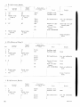
.
T0il6q30"GRR
'
t
RADIO
i
:;
SET
,,.-i?jD.
'l'.
F.
e.
AI\{IGRR-5
I!.
E
r;'
t
p*,
I
".fi
É
iit ,
i
f
4
i{.'
.
"
'
tt 3'
.W
D E P A R T M E T Y T S ' OTPH E A R M Y A N D T H E A I R F O R C E
AUGASTP52
.A,GOE13A--dult
TII 11-29J1 1'O 1(t-30-ClilÌ.;*;
RADIO
t
RTCTIVINC
SET
Af{/cRR-5
l
United States Goternnent
I'rínting
W'asltíngton: lttj2
AGO 3134
()tii, e
DEPARTMENTS OF THE ARMY AND
THE AIR FORCE
WlsnINcroN 25. D. C.. 8 Arrctttst1952
TM 11-295/TO16-30-cRR5-5is publishedfor the information and guiclzrtrce
of all ('onr'(,1'ne(i.
I A G ' 1 1 : ] . . 1("f 1t J u l 5 2 ) l
Bv oRnonoF THESrcnprlnms oF THEARMY AND THE AIn Foncn:
OrRrcrrr,:
\V}T. F]. BERGIN
IIa.ior General,USA
lÌ'lre Ad.iutatttGeneral,
J. LAWTON COLLINS
Chief of Staff, Uníted SfafesArmy
OF F IctIAL :
N. F. T\YINING
Actittg Chief ol Stalî, UtútedStafu,sAir I-ot'ce
K. F]. THIEBAUD
Crtlrttttl, LrSA-F
Aír Frtrce General
t
DlsrRteurtox:
A c t i r t ' A r t r t r t:
T e c hS v c ( 1 ) : T e c hS v cB d ( 1 ) ; A F F B d ( e aS v cT e s tS e c )( 1 ) ; A F F ( 5 ) ; A A C o m c(l 2 ) ;
O S } { a .Cj o m r l ( 5 ) ; B a s e C o m d ( 5 ) : L o s C o m d ( 5 ) : A ( 2 t l ) : l l l ) \ \ ' ( 5 ) ; C H Q ( 2 ) ; F' T 1 2 1
S c h ( 5 ) e x c e p t1 1 ( 2 5 ) ; G e n D e p ( 2 ) ; D e p 1 1 ( 2 0 ) e r c e p tS i s S e c ,G e n D e p ( 1 0 ) ; T n g
D i v ( 2 ) : P O E ( 1 0 ) , O S D ( 2 ) ; L a l r 1 1 ( 5 ) ; ] ' I i l D i s t ( l ì ) : l t h & 5 t h E c h M a i n t S h o p sl l
( 3 ) ; T w o ( 2 ) c o p i e st o e a c h o f t h e f o l l o n ' i n g T , ' O & E ' s : 1 1 - 1 0 7 ; I I - 7 2 7 A ; 1 1 - 1 2 8 :
1 1 - 5 0 0C
, l A ,C B , C C ,C D ; 1 1 - 5 8 7 ;l 1 - 5 9 2 ; 1 1 - 5 9 7 .
ly'G: Sameas Active Army exceptone col.)\'to each unit.
*
OI|C: Sameas Active Army except()rìecol)l' to each unit.
For exnlanationof distribution formulir.seeSlì :rì10-90-1.
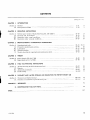
CONTENTS
Paragraph
C H A P T E Rt .
Section I.
n.
C H A P T E R2 .
Section L
IL
II1.
W.
C H A P T E R3 .
Sectiott L
II,
III,
rv.
v.
s
Pao,
INTRODUCTION
General
Description and data
1
'
3-10
O P E R A T I N GI N S T R U C T I O N S
Service upon receipt of Radio Receiving Set AN/GRR-5
Contlols and instruments
Operation under usual conditions
Operationunder unusual conditions.-
Ir-r7
18,19
20-25
26-29
8
15
1,7
18
O R G A N I Z A T I O N A LM A I N T E N A N C E I N S T R U C T I O N S
Organizational tools
Preventive nraintenanceselvices
Lubrication
Weatherproofing
Trouble shooting at organizational maintenance level
30,31 20,21
DO
9<
OO
36,37 23,21
24
:ì8,39
25
40-43
CHAPTER4 . T H E O R Y
Section L
u.
CHAPTER 5.
Sectìon L
II.
III,
IV,
C H A P T E R6 .
Section I.
u.
A P P E N D I XI .
II.
INDEX
\GO 3134
Power Suppìy PP-30tì/URR
Radio Receiver R-17,1/URR
44-50
51-68
28
37
69-87
88-91
92-97
98-102
55
7r
73
77
F I E L D M A I N T E N A N C EI N S T R U C T I O N S
Trouble shooting at field maintenance level
Repails
Alinement procedures
Final testing
A N D D E M O L I T I O NT O P R E V E N TE N E M Y U S E
S H I P M E N TA N D L I M I T E D S T O R A G E
Shipment and limited storage
Den-roìitionof n-ratérielto prevent enemy use,-
103, 104
105' 10(j
80
BO
REFERENCES
81
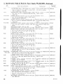
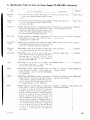
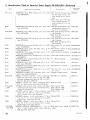
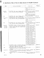
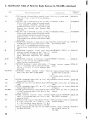
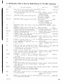
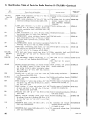
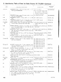
I D E N T I F I C A T I O NT A B L E O F P A R T S- _
84
107
l:l
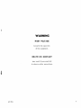
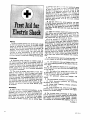
WARNING
FIIGH VOLTAGE
is usedin the operation
of this equipment.
DEATH ON CONTACT
may result if personnelfail
to observesafety precautions.
rs nc-c?sseDfcr selrty If lhe new
locatlon ls more
lhan. a fe* f611 .8.)
r:1:dcjal resplrailonb e g i v e n w t r i t c r h e r : c r . j : . u u e i n g ' _ o r J . at oulO
ii tnu
method of tnnrport.Uon prohJblts the
use of the
ShaefÍer prone prìettur rncùod. other
meihods of
resU-Ecltauonmay bc urcd fìtÚure
may be uiuatuO
on the lront of the vlcrtm'r dlrpàragm,
ó. tf,u Oìr".r
mouth.tomouth method rîày b. u!€d.
Arilndal res.
plratlo_n,onc? started, nust be
""tinrJ,
*-ìinout
loss of rhythm.
b. f,ol the vlcttm tn a prone potltlon,
one atÎn
exte-ndeddtrccily overhead, ano tÉ.
oiiu. "À Lnt
rt the etbow so that the.back or ,iu-r.,"ìaì"'ip"""
the head. The facre ehourq De turnd
away from the
bent elbow so that the nose and
mouth lre tre€ for
breathln8
RESCUE.
In case of electrtc shoc\, slyt g{ t-hehlgh
voltage
at once and sround the circults. If the hl;h
vottaie
cannot be turned ofr without delay, free
ìne vtci-til
from contact wlth the ,I::_"_lu":liri u.r.p.o-pìty
",
posslble. Avoid dlrect contact with etther
triu ir""
conductor or the victlm's b.odv.use a dry uou"o,
àl
ctothing, or other nonconductor to free-ttu-uiótirn1
An ax may be used to cut the htgh.voltage
wr"".
extreme cautlon to avold the resultlng uL.trfoìarllùri
Sy^{plOÀtS.
o. Breathing stops abruptty ln electrlc
shoc
..
jl
the current pulr"*-ir,.àugh the breathlr"
*","1
the base or the braln. Ir ihe shock tt"t-"it
ù*i'tJj
severe, the breath center recovers after
a wtrlle-aià
normal bre:"thlns ls resumed, provlded
thal ; il
flclentsupptvor alr hasbeeniurnisheo-"iùrti"
'
by artlflcial respirailon,
?' ftt" victlm ls usually very whtte or blue. R^
pulse is very weak or entirety uurunt-"nj-unfiil
sclousnesgfs complete. Burns ar€ urruff"-oÀ-.r"iì
The vtctim,s body may bec.omengfa aritid,-ìi..a
very few minutes. Thts eondlflon ls due to
th;;.ìi";
or electricltv and ls not
"9.*tg";trtc;;;;:
1î
c. Open the vlcttm's mouth and
Femove any lor.
elgn bodles, such as fatse teeth, cfre*fng
tobacco. The mouth shoutd rematn opuni ,uL, o,
irìii"tn"
longue extended. Do not permlt the victtm
to.àra*
hls tongue back tnto hls mouth or throat;
d. U an asslstant ls avallabte
durlng resusclta.
tlon, he should toos.eì any tlght "f.if,i"! ro permlt
free clreulatlon ot blood ànd to pru"unì r€strtcilon
of uroatfrtng, ie. should ,uu ìr,ut iii ,,f.trts kept
warrn,^by applylng urunxeiu-oi-oìi-u.'L"urrn",
o,
uy applyíng r,ài rocxr or uri.xr'ru-"uo*j
tn ctoth or
pape-r-to_preventInJury to the vlctlm.
The asststant
itróuto atio ue ever watchful to see.
that the vtcilm
does not r*1rro1 rrrs tongue. il-;h;il'."n'nualty
wlpe from the vlcttm,s mouth any frothy
mucus or
saitva trràt may cottect ana rniàrrererrìtr, "u.pt"a.
ilon.
e. The resuscttaung operaror chould gtraddle
the
vlcilm'! thlghs, or one teg, In suclr _unnà,
tfrut,
operatofs arrns and thtghs wgl b€ ver.
-,--.('l ..the
applvlng pnessureon the small or the
:J:l.lYhtP
vic.
[rm s_back;
o.pu.olol'g tlngers ane In a natural po.
-,.,-jrl_ $"
back*rtr, tr,uriiitiineerryrng
:It:I^"lill",ycrlm's
on the last rlb;
(t) the heels ot the hands
r€st on etther stde
as-far apart as convenlent wlthout
3-1-.11i:lt.:
al.
lowlng the hands to sllp ofi the vtcilm;
the operatot's elbows are 8tratght
and
,^-,.jj,
locked.
l. The resuscrtauon procedure
tg as fouowgr
notexeedrns
n: ,,:ii*:;"#,.;kx* pressure,
ii:ti*i +!i:i":"i$!"ry]"'ll.i,::."-i$i.,t
(?)
ordtnary and geneial tests for ssèr'r
Ouatf. lnoulq
"troriiOì"never
be aceeited.
Swlng back, suddenty rereastng pnessure.
and slt on the heels.
(t) After 2 seconds
resl, swlng fonvard agatn,
posltlonlng the hands exactly
a, buforo, "na ììpfy
pressunefor another secono.
TREAIIIENI.
o. Start artiflcial respirauon lmmedlately.
At the
same time send for a medical officer, lf
assistance ts
available. Do not leave the vlcum unattenO"*'fo"S-..Jhu- forv/ard swlng, posltiontng of the
form artlflcial resplradon at the scene
handr,
of ìfrà'"""fdo\Mnward plessure stroutd L ecàip'rì.n"o
dent, unless the victim's or operatofs
ltfe lf endan. ,Td__tl"
tn
one
mntinuous
motion, whlch nequlnesi í"*nO.
gered from such action. In thís,o"u
orrly,-rernorr" îhe rrlease and backwara swlns
tlre vtctim to another location. but no f;iir;;'L""
i ,"_"o.
ilùì*
The addlfion of the 2-secvna reat matE-"
ùtuf-àr I
î L t 3 s s 8 -D
AGO 3I3A
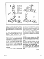
a. (oRnÍcT PoslOpootot' t cllnu t
î IO\'.
l'rc.tnít^t
dîd lxled.
hn.d
atd!
tin't
lo..
lrca l'.nl.lóot ond rcrli^g
É. lonw.tN) slt l\'(i
^N D ?OSIT IONì i(; OF
Liille jnstr
lll.\rs.
c.I)OWN$'.4nI)PnLSlltÍlE,
o.
.ítilt
and rhicùt
Rt:sî I'ostî toN.
(l yralot rclcatct prcrttc
*ùlorlg, rciny kck on
hcdq aad ntu lot 2
sec.ondsfor a complete cycle. Until the operator is
thoroughly familiar with the corr€ct cadence of the
cycle, he should count the seconds aloud, speaking
distinctly and csunting evenly in thousands. Exam.
ple: one thousand and one, one thousand and two,
etc.
h. Artiffciai iespiration should be continued until
the victim regains normal breathing or is pro'
nounced dead by,a medical officer. Since it may be
necessary to continue resuscitàtion for several
hours, relief operators should be used if available.
matic spirits of ammonia, the individual administering the stimulant should first test it himself to see
horv close he can hold the inhalant to his own nostril for comfortable breathing. Be sure that the inhalant is not held any closer to the victim's nostrils,
and then for only 1 or 2 seconds every minute.
b. After thc victim has regained consciousness,
he may be'given hot coffee, hot tea, or a glass of
rvater containing ,! teaspoon of aromatic spirits of
ammonia. Do not give ony liquíds to ai rloconaciouc
pictim.
cAuiloNs.
OPERATOR.
RETIEVING
The relief operator kneels besidethe operator and
follows him through several complete cycles. When
the retief operstor is sure he has the correct rhythm'
he places his hands on the operator's hands without
applying pressure.This indicates that he is ready to
take over. On the backward swing, the operator
moves and the relief operator takes his position'
The reìieved operator follows through several complete cycles to be sure that the new operator has
the correct rhythm. He remains alert to take over
lnstantly if the new operato: falters or hesitates on
the cycle.
STlrrlULANTS.
o. If an inhaì:rnt stimuìant is used, such as aro
o. After
QUIETLY.
may cause
the victim
weak and
gasping.
the victim
Any injury
a condition
is pale and
rapid, and
revives, keep him LYING
a person may have received
of shock. Shock is pr€sent if
has a cold sweat, his puìse ls
his breathing is short and
b. Keep the victim lying flat on his back, with
his head lower than the r€st of his body and his
hipc elevated. Be sure that thene is no tlght clothlng
to restrict the fnee circulation
of bìood or hinder
natural breathing. Keep him warm and quiet.
c. A resuscitated victim must be watched carcfully as he may suddenly stop br€athing. Nevet
prsol
alote urtil it is CE8leotse a tesuscitoted
TA,IN that he k lúIy coascúous ond bîeathi^g no?.
mallg.
ru 533E-t
AGO 3134
vll
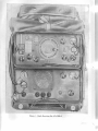
T r úa s s - r
Fi,gure 1. Radì,oReceiuitzg Set AN IGRR-í.
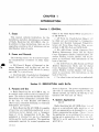
CHAPTERI
INTRODUCTION
S e ction l. G E N E R A L
l. Scope
This manual contains instructions for the
installation, operation,maintenance,ancl repair
of Radio Receiving Set AN/GRR-5 (fig. 1).
In addition to these instructions, there are t\.\'o
appendixescovering a list of referencesand an
identification table of narts.
2. Forms ond R.ecords
The following forms l'ill be used for reporting unsatisfactory conciitionsof Army eqriipment.
o. DD F orm 6, Report of Damaged or Improper Shipment, rvill be filled out ancl forrvarded as prescribed in SR 745-45-5 (Army)
and AFR 71-4 (Air Force).
ó. DA Form 468, Unsatisfactory Eqr"ripment
Report, will be filled out and forr.vardedto the
Officeof the Chief Signal Officer as prescr'ìÌl,rl
in SR 700-45-5.
c. AF Form 54, Unsatisfactory Report. rvill
be fllled out and forwarcled to Commanrling
General, Air [tatériel Command, Wright-P:rtterson Air Force Base, Dzrl'ton, Ohio, as pfescribed in SR 700-45-5 and AFR 6.5-26.
d. DA AGO Form 11-238, Operator First
Echeion Maintenance Check List for Sisr-ìal
Corps Equipment (Radio Commnnicatior-r,
Direction Findir-rg,Carrier, Raclar), r,vill be preparecl in accorclancervith instructions on the
back of the form.
e. DA AGO Form I\-239, SecondanclThird
Echelon Maintenance Check List for Signal
Corps Equipment (Radio Comrnunication,Direction Finding, Carrier, Radar), u'iil be preparecl in accorcìanceu'ith instrtictions on the
back of the form.
l. Use other forms and recorclsas authorizecl.
S e c t i o nl l . D E S C R I P T I O N
AND DATA
3 . Pu r p o s eo n d U se
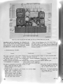
4,. Radio Receiving Set AN/GRR-5 (flg. 1)
is a mobile raclio receiver used for tactical purposes. The radio set provides facilities for operation either with a loudspeaker,containedrvithin the unit, or with Headset C\Y-49507-A
(Navy type), connectedexternally, or with both
loudspeakerand headset.
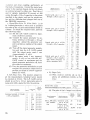
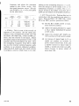
ó. Radio ReceivingSet AN/GRR-5 is capable
of receiving a-m (amplitude-modulated)or c-w
(continuous-u'ave) signals over a frequency
range of 1.5 mc (megacycles)to 18 mc. The
equipment is ir-rtencled
for use in a fixed-field
station and for mobile operation. The operating
componentsrequired for normal operation are
ACO 3134
sho$'n in fignre 4. The po\ver requirements:rre
115 volts ac (alternating current), 6 volts dc
(direct current), 12 volts dc,24 volts dc, or clr'1'
batteries (90 volts and 1.5 volts).
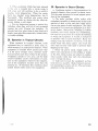
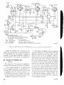
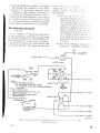
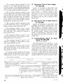
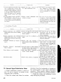
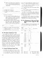
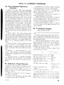
4. SystemApplicotion
( fis.2\
Radio Receiving Set AN/GRR-5 ma1- be Lisecl
alone as a conventional radio receiving set. or
with an appropriate a-m transmitter in a particular communication system. Figule 2 shon's
its application as an antiaircraft-s-alning
le'
ceiving set in conjunction u'ith Radi,, Set AN
V R C - 8 , 9 , o r 1 0 a n d I n t e r c o m m L r n i c t r t i c i nS e t
AN/UIC-1.
R A O I OR E O E I V I N G
SET AN/GRR.5
CHEST SET
GROUPAI'I/GSA-6
s4l]ol\|-sll'_av! rc-r_ _ _
_r i[E xgoMrygry.!
T f, e95-3
FigtLre2. RadioReceiuingSetANlGRR-S,tgpicalsystent.cLppl,icatíott,sintpliftecî.blocl;diogt'tr
of RodioRe5. TechnicolChorocteristics
ceiving Set AN/GRR-5
Receivertype,- --.,,
Superheterodyne.
Types of signals
which can be
--.'--.A-m, c-w, or m-c-w (modulated
received
continuous wave).
Frequency range:
Band 1-- - - - - - . 1 , 5 m c t o 2 . 7m c .
2.7 mc to 5 mc.
Band 2
- - 5 m c t o 9 . 5m c ,
Band 3--Band 4-- --------.9.5 mc to 18mc.
Type of tuning
Continuous, with provision for
presetting detents for any
10 channel frequencies.
Number of tubes:
Receiver
Po*'er supply-Intermediate
frequency
Method of
calibration-Calibration
points------
8.
4.
455 kc (kilocycle).
Built-in crystal frequency calibrator.
- E v e r y 2 0 0k c .
Audio output:
90 mrv (millirvatt).
20 mr'v.
percent or less for 70 mw
Distortion-------------.10
output, measured at 5 mc
with 400-cycle, 30 percent
modulation.
Scnsitivity:
5 uv (r.niclovolt) or better for
a-m.------------10 rnw output, rvith a signalplus-noise to noise ratio of
10 to 1.
2 uv ol bettel foi' 10 m'"v output. uiLh rt sipral-plus-noise
to noiselatio of 10 to 1,
c-w
I-f selectivity:
6 db (decibel)
- - - - - - 6 . 5k c ,
down 20 db down
- 13 kc.
40 db dorvn
20 kc.
60 db dorvn ,---- --28 kc.
Power input:
For vehicular
operation:
6 volts'12 volts
2.1voÌts
6.9 amperes,41.4watts.
3 . 2 2a u r p e l e s , 3 8 . 6
watts.
2.óó arllperes,61.2watts.
For'field
opelation:
90 volts
( 2 Battery
BA_419r'Lr)
1.5 volts
( 1 Battery
BA-405/U)
2? ma (milliampere) .
3 5 0m a .
For fixed installation:
High
Low----------
2
n',,
115 volts ac,
50 or 60 cyc
Antenna
455 rna, 52.4 watts.
-- Mast Sections 113-116-A (2
ea), MS-117-4, and MS118-A ol an1'suitable reeì
antenna.
Weight of receiver and
power supply in cabi{ ì 0 . 5l b .
net
Weight of accessories.-- 15.05lb.
AGO 3134
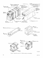
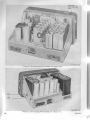
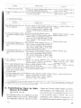
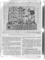
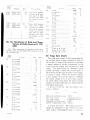
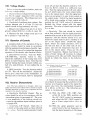
6 . P o c k o g i n gD o t o
a' \\'hen llackagecl for export shipment, the components of Raclio Rec-eivinr Set A\ GRR-5
are
p l a c e d i t r r i ' a t e r l l r o o f c o n t a i n e r s a n d a r e p a c k e d i n a w o o d e n e x p o r t c r i i t e . T r ' p i t - r r ìp i r c k i i g i l g
is
i l l t t s t l a t e d i n f i . q u r e S .T h e s i z e , w e i g h t , a n c l v o l u m e o f t h e c r a t e a r e i n c l i c a t e r l i n t h e ,, lt l' .r r i , i r r r . c h l r r t :
-\-r'l'.
f 1 9 1 1 1m
s ay be packageci in a tnanner different from that shourr, depending on snppl1cÌ1ir.1r,1.
l
i
T1-peof
packaging
-;;
Number of
I
Heiriht
(in.)
cràtes
Domestic
Export
1
1
width
(in.)
75r./+ I
9t7 r/.
461/+
OU
19
óI
t
I tn.,
Volume
T,,tr'l
rleirh:
llr,
11.1
110
162
L I
Ó. The following list indicates the contents of the cartons within the crate. Seethe packing list
attachedto the crate for the exact contents.
Carton dimensions
(in.)
10x6x44a/z__
Contents
Bae CW-206/GR containing:
Electlon Tube Case
cY-1031/URR.
Mast Sections
2 MS-116-A
1 MS-1l7_A
1 MS-118-A
Powet Cable Assemblies
Seepacking list for items in Electron Tube
C a s eC Y - l 0 3 1 / U R R .
cx-1358/U
cx-1359/U
cx-1360/u
Bag CW-212/U
Headset Cord CX-1334/U
Headset CW-49507-A
(Navy type)
1 8x 1 4 x \ 8 T s , - - - , - - - - - C o v e rC W 2 l l ' U c o n t a i n i n g :
Electrical Equipment Cabinet
CY_615/URR
Radio ReceiverR-174lURR
Pov,'erSupply PP-308/URR
Mounting MT-768/URR
Receiver-power supply interconnecting cable
Receiver and power supply are secured into
the case.Shock mounting is securedto the
case.
Shipped already connected.
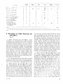
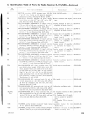
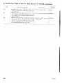
7. Toble of Components
Required
*o'
Component
Heisht
(in.)
]
Electrical Equipment
C a b i n e tC Y - 6 1 5 / U R R .
Radio Receiver
R - 1 7 . 1/ U R R .
Power Supply
P P _ 3 0 8l U R R .
Mounting -\IT ;rlR URR
C o v e rC W - 2 1 1 U
Bag CW-206.GR
Electron Tube Case
CY-1031/URR.
Mast Section l{ S- 116--{
Mast Section MS-117-A
A(ìO 3134
Depth
(in.)
l
Ì
Lencth
(in.)
Volume
(cu ft)
Unit rveieht
ílb)
.-
1
1
L
1
2
1
1.1
òfb
121/e
Orir
7%
12
18.0
51/z
8
I2
2t).
Ió rii
51iz
153/+
Ylri
11
27
e;i
1 Q
I
147/z
8.6
.ló
q a
1 1
t 1
r6f,
391/z
391/z
.15
lNTER/OR PACK
I
I REMOVE
THREE
ù rEEL
R E M O V EW A T E R P R O OBFA G
A N D L I F T I N T E R I O RP A C K
F R O M M A S T E RC A R T O N
R E M O V EN A I L S ,
U S I N GN A I L P U L L E R ,
R E M O V ET O q A N D L I F T
OUT WATERPROOF
CARTON
5 |XA|'S
UÍAUL
E
CAUTION
/LSTRUCTIONBOOKLOCATEDAT LOWER
FOPT/ANOF RlGHT slDE FILLER
-4
L : F To u r s p a R E p A R T s
A N DA C C E S S O R I E S
CARTON
/?
{,a?
;)7. '
'ta'
MASTER
CARTON
INSTRUCT/ON
BOOK
F/LLER
6 ne,.,rovr
S n E v o v Èc R A D L E
INSTRUCTIO
BN
OOK
AND FILLERS
TWO lNCH
ORANGE EAND
WATERPROOF B A G ) USED ONLY FOR
.OÀTE
EXPORT SHIPI4ENT
T
l0 nrnr
ova
B A R R I E R8 A G
I nauovr
ARTON
1l nrrurovE
I N S T R U C T I O NB O O K
I pur-rour
C A N V A SB A G
LIFTOUT
EQUIPMENÎ
F R O MC A R ' I ' O N
14nruoverwo
J | trÈL
> | tArS
1 5n e n , r o vFET L L E R
l6 nervove
E Q U I P [ 4NET
FILLER
CRATING
REMOVE
F IL L E RS
TM 295-4
Figzrre 3. Rodio Receít,ing Seú ,4N/GBR-5, packing rntd puckagíng.
4
AGO 313A
Required
C. --- i-.:
No.
<,:
. \ ' f : , - :> . ' : : ] f S - l l r
^{
I - ì l : , : :t \ \ ' - l i
L'
P, :r':.1l-:.ì .. -\-.st-nrbll'
I
I
Ileieht
rin.r
I
I
Len gth
lln.I
Depth
(in.1
linit
|
39l,b
\3r/+
96
11
57/z
Volume
(cu ft)
(-'\-:: .-. t .
t ' ': i ì - . . . \ : s e t . n b l y
P, '.',-'.1
t^\ t:ti:, L-.
':rì,le
P , , ' . .'. r ' (
-\-.sembly
.20
t.)
1
1,5
tl4
C \ 1 : l ' ì ( )U .
Htl,ìset Cold CX-1334/U
Ilecti r-t r'-Porver supply
conlt,cting cable.
H e a < 1 s e tC W - 4 9 5 0 7 - A
( )iav1' type).
hrstruction book for
Raclio Receiving Set
I
1
78
.2
óo
A
.03
11
'/2
l eight
r lt' r
.5
AN/GRR-s.
ioial
,\'ofc.
tD.Di)
This
list
is for
general
information
only.
Refer
to appropriate
parts.
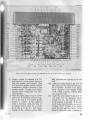
8, Descriptionoi Rodio ReceivingSet
AN/cRR_5
(fig. 1)
a. Radio Receiui,ngSet AN/GRR-S. This
equipment is a superheterodyneradio receiving
set designedfor reception of a-m or c-w signals
l'ithin the frequency range of 1.5 mc to 18 mc.
The receiver and power supply are secured in
Electrical Equipment Cabinet CY-615/URR,
and the caseis inserted into Cover CW-Zll/U.
Cover CW-211/U is securedto the cabinet with
snap fasteners ancl trvo straps which join
through the holes on the bottom skirt of the
power-sllpply panel. The front-panel control
markings have phosphorescentlettering to permit operation in the dark.
Note . T}e phosphorescentlettering u'ill be activated
for approximately 6 hours after it has been exposed to
daylight for a short period of time. To activate lettering, a source of light such as a flashlight, may be used.
b. Radio Receiaer R-17/+/LIRE (figs. 4 and
12). Radio Receiver R-174IURR is an eighttube snperheterodynereceiver designedfor reception of a-m or c-1\'signals within the frequencl' I'ange of 1.5 mc to 18 mc. The receiver
is secureclinto Electrical Equipment Cabinet
CY-615/URR by four latches located on the
sides of the case. The four holes locatedon the
sides of the leceiver are nsed as finger -qrips
for removing the receir,erfrom the case,and/or
AC;O 313A'
supDly
nublications
for
information
Ìrertainins
to requisition
of spare
for the straps of battery Bag CW-212/IJ which
may be mounted on top of the case. On top of
the upper left-hand corner of the receiver is
the antenna mounting receptaclefor the mast
sections. The front panel contains all the operating controls required for operating the receiver. These controls incluclethe band srvitch,
antenna trimmer, output switch, a-f (audio-frequency) and r-f (raclio-frequency) gain controls, bfo (beat-frequency oscillator) control,
function switch, manual-preset-tuningcontrol,
dial-light switch, antenna posts, headset connectors, and monitoring input receptacle.
c. Po'tyer Supplll PP-305/URR (figs. 4 and
13). Power Supply PP-308/URR is desienecl
to supply d-c voltagesadequateto operateRadio
Receiver R-174IURR. The power supplf is
securedinto Electrical Equipment Cabinet ('Y615/URR by four latches located on the sirles
of the case. The four holes locateclon the sicles
of the power supply are useclas fingel glilts
for removing the power suppll- fLont the case,
and the two holes on the bottom skilt at'e for
holding the straps of Cor-er'('\\'-211 U. The
power supply can be oltcltiterl I'r'r,r.r.r
it 115-volt
a-c -qource
in a fixerì instiillrrtion.oi' fi'om a 6-,
72-, or 24-volt (ì-c sr,rìr'ce
in it vel'ricnlaroperation, or as iì c()nneclinr'ltoint to the receiver
lriitteries. The front
from 90- littrì 1..-r-r',,Ìt
paneì contains the lusLrs,sllare fuses,the var-
ious controls for correct operation of the power
supply, and in addition, the loudspeaker for
the receiver. The various controls include the
power-selector switch, power on-off switch, and
speaker on-off switch.
d. Mi,nor Componentsof Radío Receiuing Set
AN/GRR-í (fiC.4). Included among the minor
componentsof Radio Receiving Set AN/GRR-5
are the headset, headset cord, mast sections,
and cable assemblies. See appendix II for complete descriptions.
2 Mast SectionsMS-116-A.
1 Mast SectionMS-l17-A.
1 Mast SectionMS-118-A.
3 tubes,type 1L4.
3 tubes,type 1R5.
2 tubes,type 1U5.
2 tubes,type 3V4.
2 tubes,type 6AG7.
2 tubes,type CK1007.
2 tubes,type OB2.
COV€R
:
cw-2rr/u
R A D I OR E C E J V E R
R-II4lURR
P*'#€R $UPPLY
PP.3C81URR
là1u,,,,
"':
M0uf''rTrr'lg
l\{T-?ùe/uRs
F 0 W E nc a S i - É
A 5 5 ÉM E L Y
c x - t 3 5 8/ U
púw[R eÀgl*r.''
ASSEMNLY
c x - r $ 5 9/ U
M O L I N T I I ' i GH A F O f J A R H
H r a 0'$Í YrPr C
IIAUY
cw-495ú7-A
EtgSîfi*,{
rJ8É CAS€
cY-io3t/uqR
BA6
{w-?ù6 l cft
FrA05[T C0R*
c x - t 3 3 4/ u
!' ,o*r* .o*.*
A$S[9Y18LV
c x - t 3 6 0 /u
fr1Àg'f r;.':
r*EeTf*fie;
i1*6:lt*."&,
I
:l
l!1$-tì7-,arAf'rll
M$ - trB-A
L.
:':rrt,::tta:.:a,:..1:.;.1!È.=-::-:t!i:."::i:::--r::..l':-::
:
:
I..
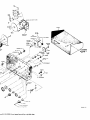
Figuve .1. Radio Recei,uingSet AN IGRR-í,
9 . Ru n n i n gS p ore s
Running spares are provided for all normally
expendableitems such as tubes, pilot lamps, and
fuses. All running spares except the mast sections are stored in Electron Tube Case CY1031/URR. The tube case and mast sections
are stored in Bag CW-206/GR (flg. a). Following is a list of running spares:
o
I
:t;,:_:l
l
T M 2 9 5 -2 1
operating components.
I lamp, dial, 2-volt, .06-ampere,GE 49, or
equal.
1 vibrator Oak No. 6556, or equal.
L vibrator Oak No. 6606,or equal.
1 fuse, l-ampere, type 3AG.
1 fuse, 3-ampere, type 3AG.
1 fuse, 4-ampere, type 3AG.
1 fuse, B-ampere,type 3AG.
AGO 3134'
1 0 . Ad d i t i o no l E q u i p me n tR e q u i red
o. Tht fi'll(,\\'illgpo\yer sourcesare not suppìietlirs l)rit'trrf RndioReceivingSet AN/GRR-5
ìrut itre rctluireclfor its installationand operatiot-t:
(1) 115 r'olts ac, 50 or 60 cps (cyclesper
second) for fixed installation.
(2) 6-volt, 12-volt, or 24-volt d-c storage
battery for vehicular installation.
(3) Two 90-volt batteries in parallel (Ba
and bias supply) and one l.5-volt battery (filament supply) for field installation.
Radio
Receiving
Set
AN/GRR_5
AN/GRR_5
ANi GRR_5
AN/GRR_5
AN/GRR_5
AC{) 3t3A
Type
b . I f t h e r a d i o s e t i s t o b e i n s t t r l l e tiìn r , r e hicle,a separateinstallationunit i-ssLrpplierl
t.r
must be requisitioned) for each vehicLrliLrinstallation,since such items as cables,junction
boxes, and mounting hardu'are var.v ri'ith the
type of vehicle. The chart below indicates the
installation units which can be used rn'ith Radio
Receiving Set AN/GRR-5 for several vehicles.
The completeequipment consistsof a basic unit
and an installation unit. The basic unit consists of items common to practically all uses of
the radio set. The installation unit consists of
all components and accessorieswhich are requirecl to install the radio set in a speciflc
vehicle.
of vehicle
Carriage, motor multiple, gun, l{16
Carliage, motor, trvin, 40-r.nmgun, M1941
Carrier, personnel,half-track, l{ilA1
Vehicle, armored, infantly, full track, T18E1
Vehicle, arnored, utility, M39
Complete
equipment
2S2505-5-V69
2S2505-5-V97
2S2505-5-V68
2S2505-5,V57
2S2505-5-V91
Basic
unit
I
12S2505-5
2S2505-5
2S2505-5
2S2505-5
2S2505-5
Installation unit
2S2505-5-V69
/50
2S2505-5-V97/50
2 S 2 5 0 5 - 5 - V 6/ 580
2S2505-5-V57/
50
2S2505-5-V9
1/ 50
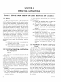
CHAPTER2
OPERATING
INSTRUCTIONS
sectionl. sERvlcEuPoN REcEtPT
oF RADto REcEIvtNG
sETAN/GRR-5
I l. Siting
a. Erternul Requirentents, The location for
radio equipment dependson the tactical situation and local conditions. Depressions,valleys,
and other lorv places generally are poor locations for radio reception becausethe surrounding terrain absorbs r-f energy. Weak or Ltndesirable signals may be expectedif the set is
operateclunder or closeto steeì bridges, Llnderpasses, power lines" or power units. Choose,
if possible,a location on a hilltop or elevation.
Fiat ground is desirable. Normally, reception
over water is better than over.land.
b. Interíor Requiremenús.The shelter for the
equipment must meet the folìorn'ing requirements:
(1) Sufficient spacemust be available for
possible repair work.
(2) The receiver should be located near
connectionsfor external power.
b. Step-B11-Step
Instructions for flncratíng
and Unpacking.
(1) Place the packing case as near the
operating position as convenient.
(2) Unpack the equipment as shorvn in
figr,ire 3. (The crate ancl waterproof
bag are used only for export shipments.)
(3) Place the equipment oÌt a u'orkbench
or near its finnl loc:rtion.
(4) Inspect the equipment for possible
damage incurred cluring shipment.
(5) Checkthe contentsof the packing case
against the master packing slip.
Nofe. Save
containels foi
'Iherr.nents.
equipment is
ment.
the original packing cases and
both expott and domestic shipc:rn be r-tsecì again rvhen the
r.epacked for storage or ship-
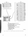
13. Instqllotionof Receiverond Power
Supply
a. General. The receir-eraucl power supply
12. Un c r a t i n g ,U n p o cki n go, n d C h e cki n g ma1' be nseclas a fixed-fielclinstailation, as a
vehicular ir-rstalìation.or as a portable field
N e w E q u i p me n t
(fig.3)
Nole. For used or reconditioned equipment, refer to
paragraph 17.
a. Getteral.
When ner,v equipment
is received,
select a ìocation where the equipment may be
unpackedwithout exposltreto the elementsand
s'hich is convenÍentto the permanent or semipermanent installation of the equipment. The
location should be chosenso that the equipment
may be Llnpacked x'ithont damaging other
erluipments.
Cautíon: Be careful in uncrating, nnpacking,
rind handling the equipment; it is damagecl
' ,sily. If it becomesdamaged,a completeovel'ul might be required or the equipment might
rendered useless.
8
installation. The ladio set is shippedwith tnbes,
vibrators. fltses,pilot lamp, and crystal already
installed. Remor-ethe pou'er supply and receiver from Electrical Equipment Cabinet CY615,/URR b1- opening the eight latches at the
sides of the cabinet, sliding the two units foru'arcì, anrl discor-inectingthe plug and recept:rcle at the rear of the receiver and porver
slrppllr, respectively. Loosen the covers by removing the scrern'sancl loosening the captive
screws,and checkto seethat all tubesand vibrators are firmly seated in their proper sockets
(fies. 5 ancl 6). See that the receiver-power
supply connecting cable (fig. 9) is connected
properly to the cabinet. When the checkis complete, reconnect the units and replace them in
the cabinet.
AGO 3134
REFERENCE
REAR
F I L A M E N TV O L T A G E
VIBRATOR
B+ VOLTAGE
REGULATOR
@9
9@@qF
oAu
I
INPUr
/
v'BRAroRl
A
71
|
I
Tlol
ll
I
\
c,,a
(
H!..1,",?:r..
)l;.11ru,,#
cK looT
c
c
6AG7
\-/
c
c
c
FRONT
TM295-tl
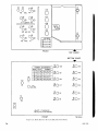
Figut'e 5. Pou.er Sttpltly PP-J0SlURR,
tttbe lctcntiott.
REAR
LLATOR
IST I-F
AMPLIFIER
tL4
CONVERTER
tR5
2D R-F
AMPLIFIER
tL4
A-F AMPLIFIER
3V4
I ST R-F
AMPLIFIER
tL4
20 I.F AMPLIFIER
C A L I B R A T I O NO S C I L L A T O R
c R -2 l U
tR5
D E T E C T OA
RV C
.A-FAMPLIFIER
Iuc
FRONT
F i g u . t c 6 . R o . d i oR c c t ' i r t r I Ì - t i
A(ìO 3134
TM 295-tO
i l'Jil:
;'. Í-i, lrl I rtstallatiott.If the equipmentis to
be expr.,secl
to the weather, keep the radio set
in ('over ('\\'-211lU. In very hot weather, the
cover should be removed to provide proper
ventilation.
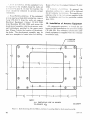
c. Fired-Field lttstullatíon. If the equipment
is to be used as a fixed-fieldinstallation, remove
Cover CW-ZLI/U from the radio set, remove
Electrical Equipment Cabinet CY-615/URR
from Mounting MT-768/URR, and secure the
shock-mountassemblywith the six screws,nuts,
and lockwashers provided in the spare parts
bag. Figure 7 shows the location of the mounting holes. The shock-mount assembly may be
used as a template to locate holes for drilling.
ReplaceIllecti'iciLllìtlLripmentCabinet Cy -GIí /
URR.
d . I ' e l t Ì c t r l a r L' r r t r r lal t í o n . I n g e n e r a l , t h e
proceciureoutlinecl in c aborrewill be followed
for all vehiculal instrrllations.For specificprocedures,refer to the instt'uctionssuppliedwith
the installation nnit for the particular vehicle
(par. 10b).
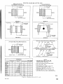
14. lnstollotion of Antenno Equipment
All componentsnecessarl'to install the antenna for field installations are pror-icledin Bag
CW-206/GR. For vehicular installationsadditional equipment is supplied with the vehicular
installation unit.
o . 2 6 5D r A ,
6 HOLES
r6t
- - î
(gr
I
(g)
A
t
?
3i ---|-
3-+.--
u-l-
NOTE:
A L L D I M E N S I O NASR E I N I N C H E S .
T 0 L E R A N C Et É ?
uà
TM 29s'9
Fìgure7. RadioReceiaingSetANlGRR-S,locationof mountingholesforshock-mountassembl,u.
l0
AGO 3134
Cuutiott: \\-hen unpacking, keep sand and
mucl flcim the ends of the mast sections.
a. F iald Irtstullations.
(1) Insert Mast Section MS_112_A into
internal threaded portion of Mast Sec_
tion MS-118-A, and tighten. Insert
Mast Section MS-116-A into internal
threaded portion of Mast Section MS_
117-4, and tighten. Insert Mast Sec_
tion MS-11G-A into another Mast Sec_
tion MS-116-A, and tighten. Insert
Mast Section MS-116-.4 into receiver
at the left-hand front portion of the
top of the case, and tighten in place
(fig.38).
(2) If tactical operation requires the use
of a reel antenna, disregard 0(1)
above, connect the antenna leacì_in
wire to the post marked A on the
receiver panel, and connect post G to
a secllreground (fig. 12).
b. Vehicu'lar Installations. Vehicular insta]_
lations require the riseof Mast Base AB-1b/GR,
suppliedrvith the installation unit. The location
of the antenna mast base,in most cases,is de_
termined by the vehicle. In general, the mast
baseshould be placedas high as possible. After
the location of the antenna is determined and
the mounting hole is clrilied, install the mast
base (fig. 8) and antenna in accordancervith the
instructions outlined belorn'.
( 1) Place one large rubber washer and the
Llpper insulator over the mounting
hole.
(2) Place the trvo small washers on the
stem of the mast base body.
(3) Insert the mast baseboclyinto the hole
in the upper insuiator.
(4) Place the other large rubber u,asher
on the lorver insulator.
(5) The ground ring strap and hosecìamp
suppiied rvith the mast base are not
required for wire lead-ins. Store these
items in Bag CW-206//GR.
(6) Insert the lower insulator into the
mounting hole from underneath.
(7) Assemble the mast base by holding
the lou'er insulator and turning the
mast base body until the mast base is
secure.
( 8 ) Screw together Mast Sections IIS116-A (2 each), MS-112-A, ancì)IS118-4, then turn the assembly inttr
the mast base.
( e )To attach the antenna lead-in to the
mast base, tin the end of the rvire
lead-in and attach it to the bincling
post on the lower insulator. Attach
the other end of the lead-in to the nost
markerl A on the receiver nanel.
Grounclthe post marked G.
M A S rB A s EB o D y
WASHERS
-
UPPERINSULATOR
R U B B E RW A S H E R
MOUNfINGSURFACE
IN VEHICLE
EOLT
L O \ r y E RI N S U L A T O R
R U B E E RW A S H E R
SOCKET
CAP
BINDING
TM 29s-8
Figure 8. Mast Base AB-1S lGR, insta,ltation.dratt,íng.
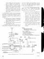
15. Connectionsond Initiol Adjustm en t
Set the POWER SELECTOR switch for the
desired mode of operation and make the an_
plicable connections as describecl belorv.
a. 115-Volt A-C Opet.ation (figs.12 ancl 1B).
Connect one end of Power Cabie Assemlrlr- ('X_
1358iU to POIVER INPUT receptacte .I103,
and secure the connector in place. ('ortnect the
male end of the cable to a 11,j-r-olt a_c llo\\.er
line.
b . 6 - , 1 2 - , o r 2 / 1 - I r r i l tf ) - C ( ) 1 , o . ( t t i r t r t .C o n n e c t
Power Cable Assemtrir'('-\-1:,ì;l) U to pOWER
II{PUT receptacle Jlrt::1u
. n t l s e c u t ' et h e c o n n e c tor in place. ('onneet the other eucl to the d_c
s o u r c e . T h i s e n r i ( . r , n t a i n s2 l u g s . C o n n e c t t h e
lug on the inner u.ire to the positive (+) ter_
,(;0 313.A.
tl
auclconnectthe lug on the
nrini,i ,'1 1]1.,sr)ul'ce,
terminal of the
shit'ld to the ttegtrtive (-)
s0tìf ce.
c. Dt'y-Battery Oyteratiott. Connect Polver
Caìrle Assembly CX-1360/U to DRY BATTERY receptacleJ104, and secltrethe connector
in place. Connect Battery BA-405iU to the
plug on the cable nearest to the power supply
chassis, and then connect tu'o Batteries BA419/IJ to the outer sockets on the calcle. Secure
batteries in Bag CW-2I2,/U'
Nofc. The initial ad.justmentbelorv is not to be tnade
rvhen the eqnipment is connecteclfor dry-batter:y opera'
tion.
d. Inítiat Adiustment. Turn POWtrR ONOFF switch S103 to ON, and allou' 5 mintttes
for warm-up time. Slide the power supply unit
partially out of the cabinet (par. 13). Connect
a 20,000-ohms-per-voltmeter to the fiIcrment
aoltage test point (J102) on the right sicleof
the porn'ersuppll' (fig'. 11) ancl adjust the frlam,ent aoltaglecontt'ol (R116) until the meter
reads 1.4 volts dc. If the proper voltage cannot
be obtained,refer to the eqllipmentperformance
checklist (par. 43). Replacethe pou'er sr-rpply.
e. Headset Connect Headset CW-49507-A
(Navy type) to Headset Cord CX-1334/U'
Connect cord to either PHONES receptacleon
the receiver.
f . Monitoring I'nput. If the radio set is to be
used to monitor the outpr"rtof another receiver,
to monitor the sidetoneolttput of an associated
transmitter, or to sltìlply a monitoring signal
to associated equipment, the MONITORING
INPUT receptacle mllst be connected to the
associatedequipment. For this ptlrpose' a nineconiluctor cable, terminated in a suitable plug,
is required. (Neither cablenor plug is supplied
rn'ith the radio set.) Circuit details of the connections to be made are included in paragraph
68.
16. PresettingRodio Receiver
R-174/U R.R.
(fig.12)
Presetting the receiver consistsof adjusting
ihe MANIIAL-PRESET TUNiNG mechanism
o allow instantaneousselection of any 10 deì rlnted channels. A signal soltrce (loosely
12
signal gettei'lrtoror distant transmitter)
coLrpie([
is lecluit'etlfot' 1ti'csettingeach channel.
A , P r c l i i i i t i t t r ' ,.rl r l. it r s t i t t e n t s ,
(1) Rotate thc IIA.NUAL-PRESET TUNING conti'r)lto see that all the numbered tletcttts :Lt'csitr.tatedwithin the
tuning:lzinlLtthìr)-lliacing the at'rou'ed
Jtole over all the tleterlts'
(2) If a detent is uol irl tl-rettlning range'
place either hoie of the ]IANUALPRESET TUNING cotrtrol over the
detent nut, place the lockirlg ke1' 6v"*
the nut, and loosen.
(3) With the key in place on the nttt' rotate the control until the cletent is
rvithin the tuning azimuth. Tighten
ancl remove the locking keY.
b. Settíng tlte Preset Chonnels.
(1) Set the BAND S\\r, and MANUALPRESET TUNiI'IG cotitrols for the
desired channel frequencY.
ltole over the closest
(2) Place the a.rrorcecl
(or clesired) numbered detent by rotating the I'{ANUAL-PRESET TUNING control.
(3) Loosen the numbererl nut by using
the locking key assembl-v,ancl lift the
ccLllLaTnL.
(4) Lezrve the locking kelr in place anci
i:otatethe IIANUAL-PRESET TUNING control back to the channel frequency.
(5) Push in the fine-tuning knob and make
a fine-tuning adjustment.
(6) Adjust the ANT. TRIMNIER control
for maximum signal.
(7) Rock the fine-tuning control to insure
maximLlm signa'].
(8) Tighten the numberednut securingthe
detent, push dorvn the cam arm' and
remove the locking keY.
(9) Write the band and frequency on the
detent-frequency chart located on the
front panei.
(10) Repeatthe procedurefor as malu/ preset channels as desired.
AGO 3134
I
ffi;un*ffT:;:x::ggffi
î
W
m
,WW
b,ii**=
"*=--u*i
ft#
lll,,
",i'';
*
#:''"'-:s
qi
;3
,àt
TÀ-É
'.:r,
"!']
Figttre 9. Electron'ícEqzr.ipmentCabinet CY-615lURR, receit:eranclporcer supply rentot,ecl.
17. S e r v i c eu po n R e ce i p to f U se d o r
R e c o n d i ti o n eE
d q u i p me n t
changes in this manual, plef eliiblr' on the
schematic diagram.
a. Follolv the instrr,rctionsin paragraph 12
for uncrating, unpacking, and checking new
equipment.
Ò. Checkthe usedor reconditionedequipment
for tags or other indications pertaining to
changes in the rviring of the equipment. If
changes in rviring have been made, note the
c. Check the operatillg cr)ntr(,ls foi' ease of
rotation. If lubricrition is lerltiii'erl. r'efer to
t h e l u b r i c a t i o n i r . r s t i ' L r 1 ' 1 i r rirnì i c Ì ' r i r p t e r 3 , s e c tion III.
.\(ìo:1134
d . P e r f o r m t h r i n . t r , i l i L t i , r n c, o n n e c t i o n ,a n d
p r e s e t t i t r g 'l ) ì ' ' , ( ' rl 'r,t t ' r - g i v e t t i l t p a r a g r a p h s 1 3 ,
14, 15. irntl 16.
t3
A È { T Eh i T $ A
r . e sér S r c T t * h J
it'JprJr
!
*
w
s+
ffi3
Figure 10. RcLòlioReceioer R-174lURR, rear oblique ,uiew.
T Wg * s * t 3
f r'r s
,.fiúf
Figtn"e 77, Power Supply PP-30SlURR,,rear obliqztet,i.eru.
l4
T M 3S5- t4:.
AGO 313A
S e c t i o nl l . C O N T R O L SA N D I N S T R U M E N T S
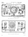
18 . R o d i o R e ce i ve R
r -1 7 4 l U R R
(figs. 10, 12, and 40)
The follorving table lists the controls of the
receiverand indicatestheir functions:
Control
Terminals A and G
Control
PHONES jacks
(J2 andJ3).
MONITORING INPLTT receptacle
(J1).
l'u n ct ion
Pi'ovicler.neanscf connecting reel
anf,enna.
Antenna itrput i'ecep- P r o v i d e s m e a n s o f c o n n e c t i n g a n tacle (on top left
tenna mast seetions.
side).
R.F. GAIII eontroi
Controls the scleen voltage of V1
(R32).
ar-rdV4.
BAND SW. (S1)
S e i e c t sh a n d i n w h i c h t h e r . e c e i v e r
is to be operated:
Posi.tíon
Bantl
1. 1.5 mc to
2,7 ntc
2 . 2 . 7m c t o
5 mc
3. 5 mc to
9.5 mc
4. 9.5 mc to 18 mc
Peaks signal input reception.
ANT. TRIMMER
Receiver por,verinpnt receptacle
(J4) (on backof
chassis).
Function
Plovide connections fol tri,, l r,
of headsets.
Provides fol connectionof rìrt, r,,
ceiver r'r'ithassociatecltr.an.rri'.' ,
t i n g c r i e c e i v i n g c q u i 1 , r 111
(par.68).
P l o v i d e s c o n n e c t i o nf n r . r . e c c i r . . i . polver supply connccting calrle.
19. PowerSupplyPP- 308/URR
(figs. 11 and 13)
The following table lists the controls of the
power supply and indicates their functions:
(C2).
Provide means for presetting as
Ì11anyas 10 channels.
Fine tunes the receiver to the desired frequency. Pulling out of
fine-tuning control, lifting of
the cam arm, and rotation of
the MANUAL-PRESET TUNING control tunes the receiver
to any one of 10 preset channels.
MANUAL-PREContlols operating frequency of
SET TUNING
receiver. Rotation of dial tunes
control ( C1A,
the receiver to the desired frequency. A dial lock is plovided
C 1 B , C 1 C ,a n d
c1D).
to prevent shifting after the
dial has been set,
B . F . O . c o n t l o l ( C 4 4 ) ACjusts the bfo for zero-beat and
tone signal.
Connects the receiver to deiiver
OUTPUT switch
(s4).
either a high-level or lorv-level
audio outpul, on the HIGH or
LOW position, respectively.
Adjusts the level of audio output,
A.F. GAIN control
( R 1 e A ,R 1 9 B ) .
Selects the type of operation,
PHN.-C.W.-NETPHN., C.W., NET, or CAL.
CAL. switch (52).
DIAL LIGIIT switch A momentary contact slritch to
(s3).
illuminate the dial lr'hen tuning.
It also reducesthe polver output
of the receiver n'hen operating
u,ith OUTPUT srvitch 54 in the
HIGH position.
Plovides means of shorting out
Antenna shorting
antenna 'nvhenchecking calibrasrvitch,
tion of the receiver.
Number tletents
(0io 9).
Fine-tuning control
(marked PULL
OUT BEFORE
PRESET TUNING).
AGO 313A
Control
Function
P O W E R S E L E C T O R Selects type of operation for
s$'itch (S101).
porver supply. This switch may
be in any position for 115-volt
a-c operation except lvhen the
receiver is operated with a
transmitter. The svgitch must
then be in either the 6V or
DRY BAT. position.
POWER switch
Turns power supply on or off.
(s103)
SPEAKER switch
(s102).
Filament voltage test
point (J102) (on
right side of
chassis).
Filament voltage control (R116) (on
right side of chassis).
POWER INPUT
r e c e p t a c l e( J 1 0 3 ) .
DRY BATTERY
r e c e p t a c l e( J 1 0 4 ) .
OPERATING
F U S E S 1 1 0 V ,1 4 . _
24V. 34.-12\r. J-\.6V.8A.
SPARE FUSIJS
lec eptzrcI e.
Switches the loudspeakel in or
out of receiver output circr-rit.
Provides nreans for rneasuling
filanrent voltage for tecciver'.
Controls filanrent voltac"e
tubes in receiver.
for
Power input cor.rnectol fot' 115volt a-c, 6-, l2-. ol jl-volt cl-c
operation.
Porr-ei'inlrLrt conni.ctor fol dlybatter'1' opelatior.r.
I ' u s e 1 r i , $t . t : . t p D l v f o t ' d i f f e r . e n t
l ) r ) \ \ ' ( . li Ì ì l r L t t V o l t a g e s .
Iìrtain-. spale fuses.
t5
DETENTFREQUENCY
CHART
F I N E T U N I N GK N O B
I{UMBEREDDETENTS
M A N U A LP
- RESET
T U N I N GK N O B
C A N 4A R M
LOCKING
K E YA S S E M B L Y
TM 295-5
Figure 12. RadioReceiterR-l74lLiRR, f rotztpanel
T M2 9 5 - 6
Figttre 73. Porcer SuppIA PP-308IURR, f ront panel.
l5
AGO 3134
s e c t i o nl l l . O P E R A T | oU
NN D E Ru s u A L c o N D t r t o N s
Cuutíon: Reception on the loudspeaker of
early modelsof the receiving set has a tendency
to becomedistorted after short periodsof operation, becauseof air pressure u,hich builds un
within the por.versupply and has no ouflet. Tà
prevent this condition, loosen the cap of
the
SPARE FUSES compartment before operating
the set. A hole has beenclrilledin the reàr of the
SPARE FUSES compartment to allow reduc_
tion of air pressure. All units which incor_
porate this expedient have a caution notice
affixed to the lower flange of the receiver front
panel.
20. Prelirminory
Control Setting
Before starting the equipment (and during
shut-down periods) set the front panel controls
as follows:
Control
P0sition
P O W E R S E L E C T O R 6V, 12V,24Y,or DRy BAT.
srvitch.
POWER sri'itch
i oFF.
SPEAKER switch
(OFF, if headset is used
]ON.
arone) .
OUTPUT switch
HIGH (LOW rvhen dry batteries
are used).
A.F. GAIN control
Halfrvay clockr,vise.
R.F. GAIN control
Halfrvay clockwise.
a n d a d j u s t R 1 1 6i o r a l e i r r l i t r go f L 4 v o l t s ( o a r .
I'd).
c. Set the BAND S\\-. su,itch (S1) to the
band u'hich incluclesthe rÌesii.etlfreqr,rency.
d. Turn PHt{.-C.W.-NtrT_['AL.srvitch52 to
PHN.
e. Tune the receiver to the clesirerlfr-ec1nenc1..
Depressthe DIAL LIGHT srvitch l.hile tuning,
only if the receiver is being operateclin itn area
that is poorly lit.
(1) If the desiredfrequencyhas not been
preset, tune to the signal by rotating
the outer ring of the MANUAL_PRE_
SET TUNING control.
(2) If the desireclfrequency has been pre_
set, pull out the fine_tuning control,
lift the cam arm, and rotate the
MANUAL-PRESET TUNING CONTROL until the at.rouecl hole is over
the desired numbered detent.
l. Adjust the ANT. TRIMNIER controt for
maximum output signal.
s. Adjust the R.F. GAIII and A.F. GAIN
controls to the desired level.
22. Code ReceptÍon
With the equipment connectedproperly for
the availablepower source (par. 1b), and con_
trols set as directed in paragraph 20, operate
NOTES
the equipment in the follou'ing manner.
1. For 115-volt a-c operation, the pOWER SELEC_
TOR switch may be in any position except when the
a. Turn the POIVER switch to ON.
receiver is used with a tr,ansmitter, The srvitch must
b. If the equipment has not been used for a
then be in either the 6V or DRy BAT. position.
week
or longer, connect a 20,000ohms per_r,olt
2. Although the OUTpUT srvitch normally is set
meter
to J102 on the power supply (fig. 11),
at LOW, n'hen porver source is dry batteries, it may be
and adjust R116 for a reading ctf.I.4volts (urr.
set at HIGH for emergency. The normal LOW settinE
conserves the batteries.
15c1).
c. Set PHN.-C.\,V.-NIIT-CAL.switch to C.W.
2 1 , R e c e p t i o no f Mo d u l o te dS i g n o l s
d. Set the BAND SW. srvitch (S1) to the
ltand
that includesthe desired frequencl,-.
With the equipment connectedproperly for
e. Tune in a coded signal and acljust the
the availablepower source (par. 15), and con_
B.F.O. control to obtain the r:lesileclpitch of
trols set as directed in paragraph 20, operate
the beat note. The desired tone mar- lte oìt_
the equipment in the follor,vingmanner.
tained by setting the B.F.O. ccrntrolto either
a. Turn the POWER switch to ON.
side of zero beat. Depress the DIAL LiCìHT
ó. If the equipment has not been used for
switch for illumination, if necessiri.r-.
r Ìr€ w€€k or longer, connect a 20,000_ohm_per_
(1) If the desireclfrequencl.has not been
,,'oitmeter to J102 on the power suppl;r(fig.
11),
preset, tnne to the signirl b1,rotating
'.,(.);134
t7
:irr. ,,uter ring of the MANUAL-PRESF-T TU\ING control.
(2) if the clesiredfrequencyhas beenpreset. pttlÌ out the fine-tuning control,
lift the cam arm, and rotate the MANUAL-PRESET TUNING CONTROL
r"rntil the arro'Lttedhole is over the desired numbered detent.
i. Adjust the ANT. TRIMMER for maximum
output signal.
g. Keep the R.F. GAIN control low for strong
signals to prevent overloading; the volume can
be regulated by the R.F. GAIN control.
23. Net Operotion
o. Repeat the procedure outlined in paragraph 2l or 22, using the frequency of the net
control station.
b. Set a numbered detent (if available and
not already set) to this frequency channel.
c. Set the PHN.-C.W.-NET-CAL. switch to
the NET position.
d. Without disturbing the receiver, tune the
ercí,ter of the local transmitter to the net-control-station frequency by tuning (the exciter)
for a zero-beat indication on the receiver.
e. Set the PH\-.-C.\\r.-NET-CAL. switch to
the PHN. or C.\\'. qrosition,as required.
l. Completethe tuning of the transmitter.
24. Callbrotion
To calibrate the receivef. Ìrerform the following steps :
o. Turn the PO\trrERsu'itch to ON.
b. Adjust the filament voltage (par. 15ci).
c. Turn PHN.-C.W.-NET-CAL. to CAL.
d. Short the antenna with the shorting srvitch
and check the calibration of the I'IANUALPRESET TUNING control over the complete
range of tuning for all four bands. A beat note
should be heard at every integral multiple of
200 kc. If necessary,tune ANT. TRIMMER
control for maximum beat signal. When the
beat note does not occur at integral multiples
of 200 kc, it is necessaryto realine the receiver.
25. Stopping Procedure
a. Turn the POWER switch to OFF.
b. Turn the MANUAL-PRESET TUNING
control to the l-f (low-frequency) end of the
tuning range of any band. This protectstuningcapacitor plates.
I J N D E RU N U S U A LC O N D I T I O N S
S e c t i o nl V . O P E R A T I O N
Note. Radio Receiving Set AN/GRR-5 is rvaterploof
and should be kept in its cabinet at all tiines except for
maintenance purposes. Tighten cap of SPARE FUSES
compartment "vhen set is not in use.
26. G e n e r o l
The operation of Radio Receiving Set AN/
GRR-5 may be difficult in regions of extreme
cold, heat, humidity, sand, mud' snow' etc. In
lrirragraphs 27, 28, and 29, instructions are
given on proceduresfor minimizing the effect
of these unusual operating conditions.
27. Operotionin Arctic Climotes
Subzelotemperaturesand climatic conditions
..,,ciAte(l rvith cold 'lveathermay affect the effi'.-,1i,1rei'ationof the equipment. Instructions
ì lrlecaLrtiousfor operation under such ad. r ' - , .r r ì n ( l i t i o t tfso l l o w :
o. Handle the equipment carefully.
b. Keep the equipment warm and dry. If the
set is not in a heated inclosure, construct an
insulated box for the set. Keep the filaments of
the vacuum tubes lighted constantly, unless
this overtaxes the power suPPlY.
c. Wear a knitted woolen cap over the earphones when operating in the open air with
headsets that do not have rubber earpieces.
Frequently, when headsetswithout rubber earpieces are worn, the edges of the ears may
freeze without the operator being conscious of
this condition. Never flex rubber earcaps'since
this action may render them useless. If water
gets into the receivers,or if moisture condenses
within them, it may freeze and impede the
actuation of the diaphragm. When this happens, remove the bakelite cap and remove the
ice and moisture.
AGO B13A
r1. \\'hen equipment rvhich has been exposed
to 111"e,,ltl is brought into a warm room, it
rr'ill sn'eat ancl rvill continue to do so until it
reaches loom temperature. When the equipment has reached room temperatrtre, dry it
thoroughll'. This condition also arises when
equipment warms up during the day after exposure during a cold night.
e. Use any improvised means to protect dry
l.ratteries,since they ll'ill fail if not protected
against the cold. Preheat the batteries. To
prevent heat loss,place them in bags lined r,vith
kapok, spun-glassfiber materials, animal skins,
or' \\'oolen clothing.
2 8 . O p e r o t i o ni n T ro p i co lC l i mq te s
When operated in tropical climates, radio
equipment may be installed in tents, huts, or,
u'hen necessar5',
in under.qrounddugoi"rts.When
equipment is installed belor,vground and u'hen
it is set up in swampy areas, moisture conditions are more acute than normal in the tropics.
Yentilation usually is ver-v poor, and the high
relative humidity causescondensationof moistnre on the equipment rvheneverthe temperatr-rreof the equipment becomeslorver than the
ambient air. To minimize this condition, place
lighted electric bulbs under the equipment.
29. Operotionin DesertClirnotes
a. Conditions similar to those encountereclin
tropical climates often prevail in desert areas.
Use the same measuresto insure proper operation of the equipment.
ó. The main problem r,vhich arises with
equipmentoperation in desert areas is the large
amount of sand or dirt and dust which enters
the moving parts of radio equipment. The ideal
preventive is to housethe equipment in a dustproof shelter. Since such a building is seldom
available trncl u'oulcl require air conditioning,
the next best precautionis to make the building
Ín rvhich the eqLripment
is locateclas clustproof
as possiblel-ith avail:rblematerials. Hang rvet
sacking over the u'inclorvsancl cloors,cover the
inside walls rvith heavy paper',and secnre the
side rn'aÌIsof tents u'ith sand to preverrt their
flapping in the r,vinci.
c. Never tie porver cords, signal cords, or
other lvire connectionsto the outside or inside
of the tent. Desert areas are subject to sudden
rvinC squalls r,vhichmay jerk the connections
looseor break the lines.
d. Take care to keep the equipment as free
from dust as possible. N{ake frequent preventive maintenancechecks(ch. 3). Pay particular
attention to the lubricants.
t9
C H A P T E R3
O R G A N I Z A T I O N AM
L A I N T E N A N C EI N S T R U C T I O N I S
S e cti o n l . OR GANIZATIONAL TOOLS
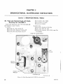
3 0 . T o o l so n d Mo te ri o l U se dw i th R o dio
ReceivingSet AN/GR.R-5
Screrv driver, 2l//2"blade
Scren'driver, 5" blade
lVrench set, midget
Tools and materials used with the radio set
are listed in a and b below.
a. Tools.
Pliers TL-13, side cutting, 6"
Pliers TL-103, diagonal cutting, 5'r
Plier::1,-126, long chain nose, 6"
b. Matet"ials.
Cheesecloth,bieached,lint-free
Paper, sancl.flint No. 000
Solvent, dry-cleaninc (SD) (Fed. spec.No.
P-S-661a)
Til*C F-!ruSTHetùFiT[i{AR
m"--
JAN*I
Là
.Jf"w*lh5
T^ú
TUSr
FULLf;A
ffiB
ffi
€ g
nfttsT*L
wflf;FrclJ
Sr Rswnntvan
î r d a . 3 3- r 5
Figure 14. Radio Receiuing Set AN IGRR-S, toolssttpplíecl.
2A
AGO 3134
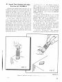
31 . Sp e c i o lTo o l s S u p p l i e dw i rh R odio
R e c e ivi n gS e t A N /GR R .-5
All the tools supplied r,vith the radio set are
locatedon the top cover of the receiver (fig. 14)
except the locking ltey assembly which is se_
cured on the front panel. In order to have
accessto the tools on the cover of the receiver,
removethe receiverchassis(par. 1S). The use
of the special tools supplied is clescribecl
belorv.
a, Tuite Puller. When it is necessaryto re_
move a tnbe, remove the tube puiler from the
cover. Place the tube puller over the tube to
be removecl. Press tool cìorvnfirml-r, over the
tube until the rvire mesh locks oir thà envelope.
Pull tube and tool uprvard rvhile rvobblin.eihe
tribe around in the socket. After the tr,rbehas
been removed from the chassis, remove the
tube frcm the tool by pushing the tube tor.varcl
the handle (fig. 15).
b, Ili'istr,l II-,, ,it.li. The Bristol wrench is
used to loosen ot tiglìten the setscrewson the
fine tuning knob ancl the gears on the band
switch and associateclmechani,qms.It also may
be used for the setscreu-s
on the ANT. TRIM_
MER OUTPUT, anct IIA\UAL_PRESET
TUt{ING controls.
c. Wrench, Double He:ra91rtrtcrl.
The clouble
hexagonal u'rench is used for lockin.s the ad_
slugs on the r-f. i-f (intelme;liirle_j.l.e_
.'iustable
quency), bfo, and crystaì-calibrator. trans_
formers and the r-f and oscillator trimmers.
d. Screu Driuer. The screw driver is usecl
in conjunction u'ith the double hexagonal
wrench for adjusting the trimmer capacitors
and the acljustal;le transformers. The screw
driver ma1'be inserted through the hollor.vshaft
of the double hexagonal wrench.
e. Tube-Pin. Stt.aiglttener. The tube_pin
straightener cannot be removedfrom the cover.
T r ú2 9 5 - t 6
Figure 15. Radio Set A|{ /GRR-i,
n t t ' t l t o r to f ì t s i L t t /| , , t j
2l
\\-hen a tube is to be inserted into the receiver,
either after maintenance or for replacement
purposes,the tube first should be inserted into
the pin straightener to aline the pins properly.
f . Locking Key Assembly. The locking key
assembly, located on the front panel of the re-
ceiyer, is used to lock the preset channel detents. It alsomav be usedto turn the OUTPUT
and POWER SELECTOR srvitches,and to remove the scre\\' ri'hich holds the spare fuses in
place.
Se cti o nl l . P R E V E N T IVEM A IN T E N A N C ES E R V I C E S
Mo i n te n o nce inspection of equipment in accorcìancervith in32. D e f i n i t i o no f P re ve n ti ve
Preventive maintenance is work performed
on equipment (usually when the equipment is
not in use) to keep it in good rvorking order
so that breakdowns and needlessinterruptions
in service will be kept to a minimum. Preventive maintenancediffers from trouble shooting
and repair, since its object is to prevent certain troubles from occurring. Refer to AR750-5.
33. Ge n e r o lPr e ve n ti veMo i n te n sn ce
T e c h n i q ue s
o. Use No. 0000 sandpaper to remove corrosion.
ó. Use a clean, dry, lint-free cloth or a dry
brush for cleaning.
(1) If necessary,except for electrical contacts, moisten the cloth or brush with
solvent (SD) ; then wipe the parts dry
with a cloth.
(2) Clean electrical contacts with a cioth
moistened with carbon tetrachloride;
then wipe them drY with a drY cloth.
Cautíon: RePeatedcontact of carbon tetrachloride with the skin or prolonged breathing of fumes is dangerous. Make sure adequate ventilation
is provided.
c. If available, dry compressedair may be
used at a line pressurenot exceeding60 pounds
per square inch to remove dust from inaccessible
places; be careful, however,or mechanicaldamage from the air blast maY result.
d. For further information on preventive
maintenance techniques,refer to TB SIG 178.
34. Use of PreventiveMointenonce
Forms
a. The information in paragraph 35 is presented as a guide to the individual making an
22
structions on DA AGO Forms 11-238 and 11239. The decisionas to which items on the form
are applicable to this equipment is a tactical
decisionto be made in the case of first echelon
maintenance by the commttnications offìcer,/
chief or his designated representative,ancl in
the case of second and third echelon maintenance,by the individual making this inspection.
Instructions for the use of each form appear
on the reverseside of the form.
b. The first two columnsin the chart in paragraph 35 serve as a cross reference betrveen
the item numbers of DA AGO Forms 11-238
and 11-239 and the preventive maintenance
information in this manual.
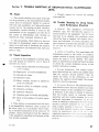
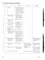
35. Performing PreventiveMointenonce
The following preventive maintenanceoperations should be pelformecl b1' organizational
personnelat the intervals inclicated,unlessthese
intervals are reduced by the ìocal commander.
Caution: Do not tighten screws, bolts, and
nuts carelessly. Fittings tightened beyond normal pressuresfor r,vhichthey are designedwill
be damagedor broken.
DA AGO
Form
11-238
item No.
DA ACO
Form
11-239
item No.
Preventive
maintenance
operations
I
DAILY
Check for completeness and general
condition of equiPment, The components are listed in ParagraPh 7
and illustrated in figure 4.
Check suitability of location and installation f or not'r.ua1operation.
Clean dirt and nroistule from antenna,
headsets, connectoi''q,jacks, plugs,
carrf ing bags, and component Panels.
ACO 3134
DA AGO
Form
11 238
item No.
DA AGO
Form
11 - 2 3 9
item No.
6
,
10
11
12
10
11
72
13
1ù
1 A
1 t
16
lr)
19
Preventive
maintenance
opetations
DAILY-continued
I Inspeet
Tn<noni
tha
caofìno
^ + readily
Ìó-,{
the
seating
of
accesI sible pfuck-out items: tubes. crystals, lamps, fuses, and vibrators.
Inspect controls for binding, scraping,
excessive looseness,lvorn or chipped
gears, misalinement, positive action.
Check for normal operation (par. 43).
.WEEKLY
Cautíon: Disconnect all power before performing the following operations. Upon completion, reconnect
power and check for satisfactory operation.
Clean and tighten exterior of components and case, mounting, antenna
posts, and connectors.
fnspect case, front panels, mounting,
antenna terminals, and exposedmetal surfaces for rust, corrosion, and
moisture.
Inspect cords, cables,wires, and shock
mount for cuts, breaks, fraying, deterioration, kinks, and strain.
Inspect mast sections and antenna for
eccentricities, corrosion, loose fit,
and damaged insulators and reflectors.
Inspect all canvas items ancl technical
manuals for tears, mildelr,, or frayinE.
Inspect for looseness of accessible
items; switches, knobs, jacks, connectors, electrical transformers, relay, capacitors, and pilot light assembly.
Inspect storage batteries for dirt, loose
terminals, electrolyte level and spe.
cific gravity, and damaged cases.
Clean dial window.
Inspect shelters and covers for adequacy of weatherproofing,
MONTHLY
Inspect electron tubes for loose envelopes, cracked sockets, and insufficient socket spring tension; clean
dust and dirt carefully; check emission of tubes.
DA AGO
Form
11 - 2 3 8
item No.
DA ACO
Form
11 239
item No-
Prer cnti!e
maintenance
operationS
MONTHLY-contìnued
Insert fixed capecitor.s for
b u l g e s ,a n r l r l i s c o l o r . a t i o n .
2l
leaks,
22
Inspect rela;z for loose mountings,
burned, pitted, or corroded contacts;
misalinement of
contacts and
s p r i n g ; i n s u f i ì c i e n ts p r i n g t e n s i o n ;
binding of plungers and hinge parts.
23
Inspect variable capacitors for dirt,
moisture, and loose mountings.
oÀ
Inspect resistors, bushings, and insulators for cracks, chippings, blistering, discoloration and moisture.
25
Inspect terminals of large fixed capacitors and resistors for corrosion,
dirt, and loose contacts.
26
Clean and tighten switches, terminal
blocks, relay case, and interior of
chassis not readily accessible.
27
Inspect terminal blocks for loose connections, cracks, and breaks.
29
Lubricate equipment in accordance
with applicable Department of the
Army lubrication order.
QI
Clean and tighten connections and
mountings for transformers, chokes,
potentiometers, and rheostats.
eq
Inspect transformers, chokes, ancl potentiometers for overheating and oil
leakage.
ùó
Before shipping
batteries.
óD
Inspect batteries for shorts and dead
cel1s.
óo
or storing, remove
Inspect for leaky waterproof gaskets
and worn or loose parts.
QN
Check adequacy of moistureproof and
fungiproof treatment.
38
If deficienciesnoted are not corrected
during inspection, indicate what action was taken for correction.
S e c t i o n | | l . L UB R I C A T I O N
36 . L u b r i c q t io nl n stru cti o n s
Cautíon: Do not allorv lubricating oil to con'rrct material such
as rubber, paint, and certain
' r.ìo 3t3A
plastics on which the lubricant ma1- have a
solvent effect.
a,. Approximately once a month clean exDosed
23
i,earing surfacesof srvitch detents,band-su'itch
nrechanisms.anclfasteners,and sparingly apply
oil, lubricating, preservative, special (PL-Special). Removeexcessoil to prevent possiblemalfunctioning of other parts, especially srvitch
contacts.
b. Approximately once every 6 months, lubricate the tuning drive gears. Expose the
gears by removing the receiverfrom the cabinet
and the top cover from the receiver, and r,vhere
possible,wipe the gears clean r,vith a lint-free
cloth moistened u'ith solvent (SD) ; then u'ipe
u'ith a dry cloth. Lubricate by appli'ing Grease
MIL-G-3278 to the gear teeth, and turn the
gear assembly to spread a light coating of
grease evenly on all gear teeth. lVipe au'a-v
excessgrease from face of gears.
Nole. If grease is removed from the tt'o setsclervs
located on the dial-gear hub of tl-re geal assembly, it
shor-rldbe replaced.
ú. Grease MIL-G-3278 contains a rust and
corrosion inhibitor. It may be used in regious
u-hich huve tempet'atllt'esranging from -70u
tr to -160 F.
37. Lubricotion Under Unusuol
Conditions
u. Arctic flr qi,,,,s. I-ul.rlicantsrvhich are
satisfactory at morlelate tenrpei'aturesstiffen
a n d s o l i d i f y a t s u b z e r rt)e n l l r e l i r t t ì i ' e s ; aas r e sult, moving palts bincl ol becomeinoperative.
When preparing the ecluipnrentî,,r krrv-temperature operation, see that lulrlicant-s used
for moderate temperatures are tholoughll' removed. Even small amoLrntsof such lribi'ictrnts,
if allorvedto remain, maf impair the opelation
of moving parts. Be sure to use Grease IIILG-3278 as specified.
b. Tt'opical or Desert Reyytons.High temperatnres and moisture causedby rain, conclensation, etc., may cause lllbricants lvhich are
normally satisfactory boflorvfrom moving parts
anclother surfaces. Inspect the equipmentcìaily
ancl lubricate it as reouired : use Grease I'IIL(]-3278.
S e c t i o nl V . W E A T H E R P R O O F I N G
38. Weqtherproofing
a. Gettersl. Signal Corps eqlripment, $'herÌ
operated Lrndersevere climatic conditions such
as prevail in tropical, ai:ctic,and clesertregions,
requires special treatment ancl maintenance.
Fungus grou'th, insects, dttst, corrosion, salt
spray, excessivemoisture, and extreme temperatnres are harmful to most materials.
b. Tropicctl X'Iaintenance. A special moistureproofing ancl fungiproofing treatment has
been clevisedu'hich, if properll' appliecl, provides a reasonabletlegree of protection. This
treatment is explained in TB SIG 13 and TB
SIG 72. The equipment is given the moistureproofing and fungiproofing treatment at the
factory and it is only necessary to use this
treatment rvhen parts are replacedor repaired.
c. Deset't X[aintenunce. Special precautions
necessaryto prevent equipmentfailure in areas
.ubject to extremely higih temperatures, low
:rLrmiclity,and excessivesand and clust are ex,l:rineclin TB SIG 75.
rI. \f/inter Maintenattce. Special precautions
24
necessaryto prevent poor performance or total
operational failure of equipment in extremely
lou' temperatures are explained in TB SIG 66
:rnd TB SIG 219.
39. Rurstproofingond Poinfing
a. When the finish on the casehas been badly
scarred or damaged,rlìst and corrosion can be
prevented by touching up bared surfaces. Use
No. 00 or No. 000 sanclpaperto cleanthe snrface
clorvnto the bare metal; obtain a bright smooth
finish.
Cuutíon: Do not use steel u,ool. Minute particles frequentl;r enter the caseand causeharmful internal shorting or grounding of circuits.
b. When a touch-up job is necessarl',apply
paint ivith a small brush. Remove rnst from
the caseby cleaningcorrocledmetal u'ith solvent
(SD). In severecasesit mav be necessaryto
nse solvent (SD) to soften the rust and to use
sandpaper to complete the preparation for
painting. Paint usedu'ill be anthorizedand consistent with existing regnlations.
AGO 3134
S C C t | OVN. T R O U B L ES H O O T I N GA T O R G A N I Z A T I O N A LM A I N T E N A N C E
LEVEL
40. Scope
a. The trouble shooting and repair r.vorkthat
can be performeclat the organizational mainte_
nance level is necessarilylimited in scope by
the tools, test equipmeut,and replaceableparts
issued, ancl by the existing tactical situation.
Accordingly, trouble shooting is based on the
performance of the equipment and the use of
the senses in determining such troubles as
burned-out tubes, damaged insulators, etc.
ó. The paragraphs which follow in this section help in determining which of the compo_
nents is at fault and in localizing the fault in
that componentto the defective item, such as a
tube or fuse.
4 1 . VÍ s u o l I n sp e cti o n
O
o. Failure of this equipmentto operateprop_
erly will usually be causedby one or more of
the follou'insfaults:
( 1) Improperly connecterlor brokerrrlower
corclsor pìugs.
( 2 ) Improperll' connectedheadphones.
( 3 ) Burned-out fuses.
( 4 ) Defective tubes.
( 5 ) Relay contacts burned or pitted becauseof overloads.
( 6 ) Inactive (dirty or cracked) crystal.
( 7 ) Defective sr,vitches.
( 8 ) Defectivevibrators.
( e ) Defectivegear or tuning
mechanism.
( 1 0 ) Dirty or bent plates of variable capacitor.
ó. When failnre is encoutrterecl
anclthe cause
is not immediately apparent, check as many of
the above iterns as is practicable before srarring a detailed examination of the radio set. If
possible,obtain information from the operator
of the equipment regarding perfor.manceat the
iime trouble occurred.
.{GO3134
c. Visuallv inspect the antenna for obvious
abnormalities.
42. Tr ouble Shooting by Using Equ i pm ent Per for m once
Checklist
a. General. The equipment perfolntance
checklist (par. 43) r,vill help the oper.ator to
locate trouble in the equipment. The list gives
the item to be checked,the conclition-qunrler
which the item is checkecì,the normal inclic:rtions and tolerances of correct operation, ancl
the corrective measuresthe operator can take.
To use this líst, f ollotu tlte items in nutnerícal
Sequence,
b. Actiotz ot. Condition. For some items, the
information given in the action or conclition
column consistsof specificcontrol settings with
which the item is to be checked. For other
items, it representsan action that must be taken
to check the normal indication given in the
normal indications column.
c. l,trorntalInclícatíons. The normal inclications listed include the visible and aucliblesigns
that the operator should perceive rvhen he
checks the items. If the inclications are not
normal, the operator shor"rldapply the recom_
mencledcorrective measures.
cl. Correctire XIt,astu.es.
The correctivemeasures listed are thosethat the operator can make
without turning in the eqr:ipmentfor repairs.
A reference in the table to chapter b indicates
that the trouble cannot be correctecl during
operation and that trouble shooting b1, an ex_
perienced repairman is necessarl,. If ilre receiver is completelyinoperatil'e or if the r.ectimmended corrective measrtresrlo not lielrl results, trouble shooting is necess:ir'1'.
llriu,er-er,
if the tactical situation rc,riuilesthirt c,tnurLrnication be maintainerl. luttl it' t he sct is not
completelyinoperatir-e.
r)t'nìLlstmaint1Ìr,r,pet'it1
tain the set in operatirrntrs lrng rr,{it is ttossibje
to do so.
25
4 3 . E q u i p m e n t P e r f o r m o n c eC h e c k l i s t
lr*^l
r
Action or
condition
No.
Antenna.
Headset CW-49507A (Navy type).
PHN.-C. W.-NETCAL. fr-rnction
sl'itch.
A.F. GAIN control,
OUTPUT HIGHLOW svr.'itch.
R.F. GAIN controi.
11
P O W E RO N - O F F
Set to maxir,num clockrvise position.
Set to HIGH position
(LO\V rvhen dr,y battelies ale usetl) .
Set to maximum clockr.viseposition.
Set to OFF position.
Set to ON position.
slvitch.
T
26
Correctiye
measufes
Mast Sections MS-116-.4,
(2 ea\ , MS-117-A, and
MS-118-A connected
to antenna input, or
reel antenna connectecl
to tenninal A on front
panel. G terminal connected to a secure
ground,
Headset plugged into
Headset Cord CX13341Ug'hich is conn e c t e dt o P H O N E S
jack.
Set to PI{N. position.
POWER ON-OFF
s."vitch.
Set to ON position.
SPEAKER ON-OFF
srvitch.
P O W E R S E L E C T O R Set to 6V, l2Y ,24Y, ot
DRY BAT. position de6V_12V-24V-DRY
pending on voltage
BAT. switch.
source. For 115-volt
a-c operation. set
su'itch to 6V or DRY
BAT. position. ( See
par,20).
PowerCableAssem- Connectedto POWER
INPI-T oI DRY BATbly CX-1358/U,
TERY receptacle.
C X - 1 3 5 9 / Uo, r
Other end connected to
cx-1360/u.
powel soufce.
Y
N"rnraÌ
inclicati0n
t2
Filanlent voltage control.
l o
DIAL LIGHT srvitch. Depress.
A 20,00O-ohm-per-volt
rnetel connectedto
J102 and chassis.
Fasten securely. Connect
according to instr'uctions given in paragraph 15.
After short warm-up
Check proper fuse and
period, rushing noise is
tubes. Refel to chapheard in speaker and
ter 5.
headset,
Voltage should be 1.4
Adj ust fi lament-voltage
volts dc"
contlol. Check vibrator El 0:l :rnd po'il'ersuppl1'tubes. Refer to
c h a p t e r 5' .
Dial liEht is illuminated. Chechlight, and switch
S3. Re-telto chapter 5.
AGO 31gA
t r " - l
i';. I
74
to
lo
1n
o
P
\(;o 3134
I
I
Nornra i
inilication.
Corrective
measures
i
R.F. GAIN and A.F.
GAIN controls.
OUTPUT HIGHLOW su'itch.
MANUAL-PRESET
TUNING control.
M
S
T
I
B A N D S W . ,P H N . - i Set BAND SVy'io posiSignai heard every 200
C.W.-NET-CAL.
tion 1 and PHN.-C,W.kc on all bands.
srvitch,and MANNET-CAL. srvitch to
UAL PRESET
CAL. Rotate MANTUNING control.
UAL-PRESET TUNANT. TRIMMER.
U
Action or
condition
Item
18
BAND SW.
19
PHN.-C.W,-NETCAL. srvitch.
20
B . F . O .c o n t l o l .
21
PHN.,C.W.-NETCAL. switch.
22
PO\YER ON-OFF
sn itch.
ING control over entire band.
Adjnst for maximurn sig- Signal strength varie-qas
nal strength.
ANT. TRIMMER is
adj u sted.
Turn counterclockrvise, Signal strength decreases.
Set to LOW position.
Stre'ngth of output signal decreases.
Tune acrossthe entire
Signals appear at reband as test signals
spectivetest freqnenare applied.
c i es .
Checl<each band. LIsethe Same as norr-nalindicaprocednle in steps 14
tions in steps 14 and
and 17.
t7.
Rotate to C.W, position" Tone signal shoLrldbe
Provide a C-W test
heard.
signal.
Rotate B.F.O. trimmer.
Tone signal varies in
pitch.
S e t t o C A L . p o s i t i o n .R o - Signals heard every 200
tate MANUAL-PREkc on all bands. If necSET TUNING control.
essary tr,rneANT.
TRIMI\,IER contlol for
maximLrmbeat signal.
Turn to OFF position.
No signals are heard.
If sìenals are u'eak or
rtot olrfnins6l,ghssll
t u ì , 1 ' 'i l t t h c I ' e c e i v e r
lnrl pou'elsupply.
I n s p e c tA \ T . T R I l I MER fot' beittplzrîes.
R e f e l t o c h a l r t e li .
Checl<tubes. Re'for.to
chapter'5.
Refer to chapter 5.
Refer to chaptei.5.
Refer to chapter'5.
Rotate B.F.O. contlol.
Check V7. Refer to
c h a p t e r5 .
Refer to chapter 5.
Check V5. Checì<clystal. Refel to chzrpter5.
] Clteck ss.itcl.rS10:1.Refer
: to chapter 5.
I
27
CHAPTER4
THEORY
S e cti o nl . P OWE RSUPPLYPP- 30S/URR
44. Block Diogrom
(fig. 16)
a. Operating voltage for the receiver is obtained from Power Supply PP-308/URR. This
unit operatesfrom a standard 115-volt 60-cycle
line; a 6-, \2-, or 24-vo1t,d-c vehicular storage
battery i or a 90-volt and 1.5-volt dry-battery
source. Output voltages are 90 volts dc -+3
volts, 1.4 volts dc, and-4.2 volts dc.
b. For 115-volt a-c operation, the line voltage is stepped down by a transformer and the
lower voltage is suppliedto rectifler CR101 (fig.
18). The rectified voltage energizesrelay K101.
When relay K101 is energized,the 115-volt a-c
line is completedto the rectifier circuit associated with V102, and the output of rectifier
CR101 is supplied to fllament voltage vibrator
E102. Bias and hv (high voltage) are developed
by the circuit associatedwith V102. Filament
voltage is developedby V104, 8102, and CR102.
Regulator tubes V101, V103, and V104 maintain substantially constant output voltages.
c. For 6-volt, L2-volt, or Z4-volt operation,
the input voltage energizes vibrator E101,
which develops an alternating voltage to drive
the rectifler circuit associatedwith V102. Rectiflcation, filtering, and regulation are the same
as for 115-volt a-c operation. E102 also is
energized by the input voltage (K101 is inoperative) and, in conjunction with V104 and
('R102, developsfilament voltage.
d. For dry-battery operation, the voltages are
upplied from the batteries to the receiver
through the power supply.
28
+ 5. H- v Rectifier Filom
,
entVoltoge,qnd
Voltoge R.egulotion
Circuits
(fig. 17)
a. In all modes of opera"tion,except dry-battery, the h-v rectifier develops the Bf, bias,
and filament voltages for the receiver. Voltage
regulation is useclto deliver a constant output
despite changes in input voltage. In the follou'ing analysis, the circuits connectedto the
secondaryof transformer T102 (common to all
modes of operation) are discussed in detail.
Primary voltage of T102 is cliscussedin detail
in the analysis of the different moclesof operation (pars. 46 through 50).
b. High voltages from the transformer secondary are connectedto the plates of rectifier
tube V102 (type CK1007) through hash filters
L111 anclL112. CapacitorC113 is a buffer for
the vibrator circuit associatedwith the primary
of T102 during 6-, l2-, and 24-r'olt operation
(pars. 47 through 49). Since each plate is connectedto oppositeends of the transformer secondary and the center tap is returned to ground
through resistor R109 (or resistors R108 and
R109), tube V102 operatesas a conventional
full-rvave rectifier. The pulsating dc is filtered
by capacitor C114 and bleecierresistor R110.
c. Resistor R108 in the B- circuit is shorted
to ground through section 6, rear, of POWER
SELECTOR switch 5101 for all mociesof operation except DRY BATTERY, and resistor
R109 is used to developbias for tubes V7 and
V8 in the receiver. For DRY BATTERY operation, resistor R10B is adclecìin series with
R109. The bias voltage is suppliedto the receiverthrough pin 8 of J101.
AGO 3ì34
FIL AUENT
VOLTA6E
VOLTA6E
atas
voLra6€
B+ VOLTAGE
REGULATOR
v t0 l
HIGHVOLTAGE
tcu
I tt tEt
vro2
V IB R A T O R
R E C T I FEI R
c Rr 0 l
F IL A M E N T
VOLTAGE
REGULATOR
vt04
F IL A M E N T
VOLTAGE
VIBRATOR
Er 0 2
F IL A M E N T
VOLTAGE
R E C TI F I E R
c Rr o 2
F/LAn'tEn/r
VOLTA6E
TM 295- r7
Figure 16, Po'*-er Sttltplg Pf'-308 lU RR, block dia grant.
^
r/. For 115-volt a-c operation, the positive
\r,lf11-sact'osscapacitor C114 is sr-rppliedto
the receiver through series regulator V101, resistor R111, contacts 3 and 2 of relay K101,
and pin 6 of J101. For d-c operation, contacts
of POWER SELECTOR srn'itch5101 and contacts 1 and 2 of K101 are used in place of relay
contacts 3 and 2.
e. The positive voltage across C114 also is
supplied to contactsof filament voltage vibrator
E102 through a series circuit u'hich includes
regulator V104, resistors R115 and R116, the
primary winding of T103, and chokesL109 ancl
L110. Operation of the vibrator is explained
in g belor.v.
.f. Seriesregulators V101 and V104 maintain
the receiver B r and filament voltagesconstant,
despitechangesin input voltage. For this purpose,the full positiveoutput acrossC114is suppìiedto the platesand screensof V101 and V104
and the control grids of these tubes are maintained at a constant potential b-vthe action of
reference-voltageregulator V103. The reference-voltageregulator is connected in series
.\GO 3134
with current-limiting resistor R113 betr,veen
the full Bf output and gronnd. If the R;
voltage increasesor decreases,the resi-stance
of
V103 changesso as to maintain a constantvoltage acrossthe tube. It is this constant voltage
which is supplieclto the control grids of V101
and V104. In the case of V104, the voltage is
supplied through isolation and gricl-currentlimiting resistor R114. Although the control
grids of the regulators are held at a constant
potential, variations in Bf voltage (becauseof
the variations of input voltage) are present at
the plates of these tubes. Variation in plate
voltage causesa change in plate current ancl a
corresponclingchangein cathodebias. Althougir
an increased plate potential lolrrersthe re-qistance of the regulators, the resultant increase
in bias raises the resistance. Similarly, rlecreaseclplate voltagecalrsesincreaseclresistance
and decreasedcathode bias, br,rtthe decreased
bias causesa decreasein resistance. The rrr-erall effect is a substantially constant loacìltotential at the cathodesof V101 and \-101. The
cathodepotential of V101 is suppliecìto the le-
29
t't.irri' ii: ll- r'oltage(d above)and the cathocle
pr-rteutialof V104 is supplied to the fllamentvoltagevibrator, E102. PotentiometerR116 in
the cathoclecircuit of V104 provides a means of
acljusting the level of voltage u'hich is suppliecl
to the vibrator.
-Yofr.. Tl-remetal cases of the 6AG7 regulator tubes
are cor.rnectetl
to the suppressol grids n'hicli ale at a
high potential above grouncl. Do not leplace tìte insr:lated clamirs r-rsedon the 6AG7 tubes lvith the inetallic
clar-npsnsed on the CK1007 tube.
g. Filament voltage for the receiver is developedrvhen the coil of vibra.tor E102 is energizecl. For 115-volt a-c operation, the coil is
energized by the rec[ified output of T101
through nolntuìlr' r,peti contacts 20 and 21 of
rela1. K101. Fi,i. 6-. 12-. or' 24-r'olt d-c operation, a d-c voltrLct'is sultplied to the coils
t h r o u g h t r o r m a l l l ' c l o : t , r l c r ) ì l t i ì c t s2 7 a n c l 2 2 o f
r e l a y K 1 0 1 ( p a r s . - 1 7t h i ' o u g h J l ) . D - c r . ' o l t a g e ,
to be interrupteci ltr- the lilri'iLtor. is suppliecl
f r o m t h e c a t h o c i ec i l c r - r i t o f \ - 1 0 1 t h l o u g h t h e
lrrimar;' of transformer T10:l artrl coils L109
a r - i dL 1 1 0 . C a p a c i t o r s C 1 1 5 , C I 1 6 . a n d C 1 1 7 , i n
conjunction n'ith Ll08, L109, ancl L110. are
hash filters. Changing the setting of R116 regulates the d-c voltage to the vibrator. C119 is
the buffer capacitor. The interrr-rpted cl-c voltage is stepped clorvn by transformer T103 ancl
2
3
5
6
7
I
r0
DC OPERATION
!1u_!!.11-ì!!!!..1]rl
s r 0 rs B o w Nr N
6 V P O S IO N + i 4 v D C
t7 vac
r
cllT
O22UF
I
FILAÀ.{EN'T
VOLTAGE
-- :
vreÀaiof
E 102
|
:
LOCAÍEO IN
ELECfRICAL
EQUIPMENT
CABINEf CY-6Is/U
{ P / O R E C . P W RS U P P L Y
CONNECTIN
CG
ABLE)
__.,j
I
LrLo
6oouH
FORil5VAC
OPERATION
I
I
IOUH
cil5
.047UF
cill
t200 uF
I
F O RI I 5 V A C
OPERATION
-+-.2oÈa
xrol
2l
FOR DC
OPERATION
I
U N L E S SO T H E R W I S EI N O I C A T E D
V A L U E SA R E I N O H M S
ALL RESISTANCÉ
V A L U E SA R E I N
ALL CAPACITANCE
I C R O F AA
RD S .
MICROM
VALUESARE IN HENRYS
ALL INDUCTANCE
=I,OOOOHIVS
2.K
3. MEG= I,OOo,OOO
OHMS
4. MH . MILLIHENRYS
6. UH = MICROHENRYS
?. UF = MICROFARADS
FILAîVENT VOLTAGE
TEST POINT
FOR OC
\ OPERAT1ON
s rol
sEcT.5
REAR
. O ' Î A T EC O U N f E R C L O C K W I S E .
8 . S W I I C HS E C f I O N S . A SV ] E W E O R
9 . R E L A YK I O I I S A C I U A Î E OO N L YI N I I 5 V A C O P E R A ÍC N ,
I O . S W I T C HS E C T I O ND E S I G N A T E O
N O .I I S
N E A R E S Î Î H E K N O BE N O ,
i l . c o N T A c f s 0 F R E L A y k l o t t N N 0 R M A Lp o s t T t 0 N .
TM 295-ìE
F i g u r e l 7 . P o u s e r S u p p l A P P - 3 0 8 l U R R , h - a r e c t i f i , e r t. o l t a g e r e g u l a t o r , a n d l t l c t m e t t t . t ' o l t c L g e s u p p l y ,
J ttitctíonrLIscltentcttic,
30
AGO 3134
feclto seleninmrectifier CR102,locatedon Electrical EquipmentCabinet CY-615/iURR,
through pins 2 and 4 of J101. The fllter circuit,
coìllectecl to the center tap of the seconclary
u-inclingof T103, consistsof L106, L107, C110,
and C111. The filament voltage is fed to jack
J102 and to pin 11 on J101 through relay K101
contacts 6 ancl 5, for 115-volt a-c operation, or
through POWER SELECTOR si.r'itch5101 ancl
normall-t'cioseclcoutacts4 and 5 of relay K101
for d-c operation.
46. Anolysis of | | 5-volt A-c Operotion
(fie. 18)
For 115-r'olt a-c operation, the line voltage
is sr-rpplieddirectly to h-v transformer T102
(par. 45ó) ancl a steppecl-dou'na-c voltage is
supplieclto the driving coil of filament-voltage
v i b r a t o r E l t t l t l r r r r ' .. l i , r t . O 1 ' 1i.,f1 i , , 1, 1, f 1 ' r , , u L , r '
S U p p l l ' o t r 1 1 5 \ ' r , l i >l r r i . l t l , i t ' n t ' t l , ì r l l : , ,Ì il ì e
'l'(
)IÌ .r,,'i:tìr>ltt1.
setting of PO\\'ER SEI-l.t
Circuit details al'e iÌs îr ,lr,,r','r'
o..The 115-volt line itt contir(l> -\ l,l,ì lt ,'l
P O W E R I N P U T r e c e p t a c l eJ 1 ( ì : li s r , l ì u t . t t"'lr ì î , r
the primar;. of T101 through fuse l'lrrl ( I1l\'.
e
1 A ) , a n d s e c t i o n 1 o f P O \ V E R O l - - O F I " s r . . ' i îh
S103. Capacitors C1024 ancì C102Fl alc littt'
f i l t e r s . T h e s e c o n d a r l rv o l t a g e o f T 1 0 1 i . i ' L ' r ' . i f i e d b y C R 1 0 1 , f i ì t e r e c lb y C 1 0 1 , a n c l f e c l t o t h e
operating coil of relay K101. \t7hen K1(.)1 is
energized, the 115-r'olt a-c line is completecì to
the primary of T102 through rela-v contacts 1-1
ancl 13, and the 6-r'olt cl-c output of the rectifier
is sr,rpplied to fiìament-voltage r.'ibrator E102
through relay contacts 20 and 21.
b. In this mode of operation, rvincling 1*4 of
+ t . 4 VD C
Jlo3
R E L A YA N D F I L A I V E N T
V I B R A T O RR E C T I F I É R
cRtol
^.T- |
6 V O CT 0
E/02 THRULIOS
'lla'
ctol
'1- I 2 00 u F
I
RELAY
Kr o l
co r L
:I
J t0t (PtN 8)
il Tt02
5 0 - 6 0c P s
PRIMARY
3 8 0V
.ta
SECONOARY
ro Ht6H
VOLTAG€
FECTIF/EN
Rrol
N O TE S :
I . U N L E S 9 O T H E R W I S EI N D I C A T E D :
VALUESARE IN OHMS
ALL RESISTANCE
15.9 V
.6sa
SECONDARY
qrnl
éllf' s
e
AND"P
FRONT
2. UF = MICROFARADS.
N O .I A R E
S W I f C H S E C T I O N SD E S I G N A I E O
N E A R E S Î T H E K N O BE N D .
POSITION,
R E L A YK I O I S H O W NI N A C T U A T E D
5
T M2 9 5 - t 9
EO U N T E R C L O C K W I S E
S W I T C HS E C T I O N S , AVSI E W E D , R O T A TC
Figure
\(ìo 3134
78. Pot'oet' Sultplg PP-3081URR,115-i:olt
t L - c r t l t t ' ,t L t t " "
t
:tÌr'-,,.,;tiC,
3l
T102 is connectecl
as a secondarywinding, and
the r-oltageclerelopeclis used for the filaments
rif \-101 ancl\'104. The filamentsare series
con_
necterlacÌ'ossthe winding in serieswith resistor
R101.contacts9 and g of relay K101, and con_
tacts 11 and 12 of relay K101.
c. The voltage acrosssecondarywinding 1B_
14-75 of T102 is supplied to the h_v rectifier
where it is utilized as explained in paragraph
45.
47. Analysisof 6-volt D-c Operotion
(fig.1e)
For 6-volt d-c operation, the input voltage
is supplied directly to the driving coil of fila_
ment-voltagevibrator E102 (par. 45g) and to
the coil and contacts of input vibrator E101.
Vibrator E101 developsan a-c voltage rvhich is
supplied to the primary of T102.
a. The 6-volt d-c potential required to ener_
gize the vibrator is supplied from contact B
of
J103 to contact B of E101 througli section 1 of
5101, fuse F104 (GV. 8A.), paralleledconracts
7 and 8 of sections 1 and 2 of 5108, normally
closedcontacts28 and 24 of relay K101, section
2 of 5101,and L101. The combinationof capac_
itor C104 and coil L101 make up a hash filter.
Sections1 and 2 of S103 are connectedin naral_
lel to prevent burning of the contacts.
b. The 6-volt d-c potential to be interrupted
at contacts2 and 5 of E101 is fed from contact
B of POWER, INPUT receptacleJ10B to con_
tact 2 of input vibrator E101 through section
1 of I'O\îER SELECTOR sr,r,itch5101, f,use
Fi04, section 2 of POWER ON-OFF switch
5103, contacts 26 ancl25 paralleled by contacts
27 and 28 of relay K101, section B of 5101,
winding 7-6 of T102, section4, front, of S101
and L102. The 6-volt d-c potential at terminal
7 of T102 also is fed to contact 5 of E101
through the primary u'inding Z-8 of T102, sec_
tion 1 of 5101, and L104. The voltage to be
ìnterrupted at contacts1 and 4 of E101 is taken
l'rom the junction of contacts25 and 2g of K101
rrclis fed to terminal 4 of TI02 through section
of 5101. From terminal 4 of.TI02, the voltage
32
is fed to contact 1 of E101 through winding
4-3 of T102, section2 of' 5101, anclL10b. The
r.oltageat terminaÌ -1of T102 also is fed to con_
tact 4 of E101 ilrlough s-incling 4_5 of "1102,
section 6, front, of S101, ancl L108. L101
through L105 and C104throLrghC10gare hash
fiiters. Capacitor C10g is a lir-refilter. Capacitor CI12 is a buffer capacitor. \\:hen the vibrator is energized, pulsating cl_cvoltage is de_
veloped across u'indings g_4_b and 6_Z_g of
T102. The secondarycircuits of T102 are the
same as describedin paragraph 45.
c. The 6-volt potential at contact B of
POWER INPUT receptacle J10B also is sup_
piied to the operating coil of filament_voltage
vibrator E102 through section1 of S101,fuse
F104, paralleled contacts Z ancl g of sections1
and 2 on 5103, normally closedcontacts28 and
24 of relay K101, section 1 of 3101, and con_
tacts 22 and 21 of relay K101. (Refer to pura_
graph 45g for circuit details of vibrator E102.)
d. For 6-volt operation, the heaters of V101
and V104 are connectedin parallel. The 6_volt
d-c potential required for the heaters is taken
from the junction of contacts25 and 2g of K101
and is suppliecl through contacts T ancì g of
K101 to pin 2 of V101, and through section b
o f 5 1 0 1 a n d c o n t a c t s1 0 a n d 1 1 o f K 1 0 1 t o p i n
2 of Y704. Pins Z of V101 ancl V104 are con_
nected together ancl completed to ground
through section B of S101 and contacts 1g and
19 of K101.
48. l2-volt D-c Operotion
(fig. 20)
The circuit of the power supply for l2_volt
operation is similar to that for 6-volt operation,
except for the addition of series resistanceto
limit the current to the vibrator coils, the use
of different taps on transformer T102, the series
connectionsof the heaters of V101 and V104,
and the fuse used.
a. Voltage for the clriving coil of vibrator
E101 is suppliedfrom J103,contactB, through
section1 of POWER SELECTOR switch 5101,
fnse F103 (72V.4A.), parallel contacts ? and
8 on sections 1 and 2 of pOWER ON_OFF
AGO 313A.
FroNwPE
Rl
Uî
I
|
Jr o 3
s tol
sEcf. 2
FRONTANOREAR
sr 0 l
6V DC TO E/02
THRU LlO8
22
S E C TI,
FRONT AND
sr o l
+6V DC
REAR
F R O N Î A N OR E A R
+ l . 4 VD C
tq
slol
sro3
F R O N TA N DR E A R
vlol
Kt o l
23
24
26
25
t t z 7
@
lurr
I
lTowER-l
F; Et o l
sr 0 l
V IB R A I O R
SECI 3
F R O N TA N D
R EA R
--JH
4l
-^
cros lSrOr
. o a z u r| é È ó r . o
vrY
Or N- r- . 4 5
,,,,
II rFn R
-oto
c,oi I
-o47 UF I
srol
sEcT.I
F R O N TA N D
R EA R
I
st0l
SECI 2
FRONTANDREAR
I . U N L E S SO T H E R , W I SIEN D I C A T E D I
A L L C A P A C I T A N CV
EA L U E SA R E I N
MICROM
ICROFARADS.
V A L U E SA R E I N H E N R Y S
ALL INDUCTANCE
UH = MICROHENRYS.
5. U F : M I C R O F A R A D S .
4,
S W I T C HS E C T I O N S
D E S I G N A T ENDO . I A R E
N E A R E S Î T H E K N O BE N D .
5.
C O N T A C Î SO F K I O I N O R I V A L LC
YL O S E D .
6.
s w r T c H s É c T r o N S , a s v l E W E D ,R o T A T EC O U N T E R C L O C K W T S E .
'iM
295.20
Figu,,'e19. Pouer Sultply PP-?08 lURR,6-aolt d-c optetcr.tiott,
functional schematíc.
\(;o 3134
33
switch S103.contacts23 and 24 of relay K101,
sectiorl 2 of S101, resistor R104, and L101.
R104 clrops the l2-volt input voltage to the 6
volts required to energize E101. The combination of L101 and C104 makes up a hash filter.
D. The l2-volt d-c potential to be interrupted
by the vibrator is fed from POWER INPUT
receptacleJ103, contact B, to pins 1 and 5 of
vibrator E101. The voltage is fed through section 1 of POWER SELECTOR switch 5101,
fuse F103, section2 of POWER ON-OFF switch
5103, contacts 26 and 25 paralleled by 27 and
28 of relay K101, to section3 of POWER SELECTOR switch 5101. From this point, the
voltage is suppliedto contact 5 of E101 through
winding 6-9 of T102, section 1 of 5101, and
L104, anclto contact 1 of ElOl through winding
5-2 of T102, section2 of 5101,and L105. C112
is a buffer capacitor;capacitorsC107and C108,
in conjunction with L104 and L105, are hash
filters. The interrupted voltage is used as the
primary voltage for T102. High voltage is developed in the secondary of T102 in the same
manner as describedin paragraph 45.
c. Voltage for the driving coil of vibrator
E102 is taken from the junction of contact 24
of K101 and contact 12 on section 2 of 5101,
and suppliedthrough section1 of S101,resistor
R102, contacts22 and 21 of K101, and L108.
Resistor R102 drops the input voltage to 6 volts.
Operation of E102 is described in paragraph
45s.
49. 24-volt D-c Operotion
(fig.21)
In 24-volt operation. the circnit of the power
supply is the same as for' 12-r'olt operation, except for the addition of r-olta.ee-clropping
resistors, a change in the rvinding used as primary of T102, and the use of fuse F102 (24V.
3.{.).
o. In this mode of operation, resistors R102
and R103 are in series,and R104 and R105 are
in series, to limit the current to the driving
coils of the vibrators. Operation of the vibrators is the sameas for 12-volt operation. Windings 1-5 and 6-10 are used as the primary of
transformer T102. Resistor R107 is used to
limit the current through the primary r,vindings,
thus reducing the primary interrupted voltage
to give a secondaryvoltage of the same magnitude as the other modes of operation.
b. The filaments of V101 and V104 are connected in series,with resistor R106 to limit the
current and to reduce the 24 volts input to 12
volts across the heaters.
c. The 24-volt d-c potential is taken from contact 24 of K101 ancl connecteclthronsh section
4, rear, of 5101 to pin 1 of J101 as a leceiver
disabling voltage sorlrce.
50. Dry-botteryOperotion
(fig. 22)
In dry-battery operation, the power supply
is used merely as a connecting device.
a. B+ voltage (90 volts dc) is fecl from DRY
BATTERY receptacleJ104, contact A, to pin
6 of J101 through section 1 of POWER ONOFF srvitch5103,section4 of POWER SELECTOR srvitch S101, and contacts 1 and 2 of rela1' 11191.
d. In the 12-volt operation, the heaters of
V101 and V104 are connectedin series. The
required 12-volt potential is taken from the
junction of paralleledcontacts27-28 ancl26-25
on K101 (o above) and is connectedacrossthe
heater through contacts 7 ancl 8 of K101, contacts 11 and 10 of relal' K101, section 3 of
-s101,and contacts19 and 18 of relay K101.
b. Filament voltage (1.4 volts dc) is fed
from J104, contact B, to J102 and pin 11 of
J101, through section 2 of 5103, section 5 of
5101,and contacts4 and 5 of relay K101.
rr. The 12-volt d-c potential available at con, t 24 of K101 also is connecteclthrough secn 4, rear, of 5101 to pin 7 of J101. This
tential is used for receiver disabling.
c. Bias for tubes V7 anclV8 in the receiver is
suppliedfrom J104, contact D, to pin 8 of J101.
Pin 8 of J101 is -4.2 volts clcfrom ground becanse of the ground retllrn through resistors
R109and R108.
3+
AGO 313A
o
O
-o No
À
nl
\t
î
@
$
o)
ui
A
()
,.rr9
o
s?-
3P9
a
o (.r)[<r
o
sî
b
,a, Q
atlJl
\^*q
(r
F
Z.
N
É E
O <
t!u
oK.
(.)Q.
^
J
O
+
Y
I
^'F
J
('r)u v
:' u
z
-:-^'^^(D
o
9
P a
J
<.>
= = ó =
u = z =
!
+
\t
U
O
iìi <
N
N
lrJ
: <
u
F o
lz
sf
oÈÈ
o
=
F
ts
Y
E
l-
ì o Z
( , Z Y
z.o
lr-
a
?
-:í
6
o
Y
!
O - u L
ts**."
( i . ) - ' F F
É.
N
(r
on
G
..,r-f
zrr.
r-#
, ' z É
ÉN
oo
0
f iP e
r)(')|J-a
É.2
l!<
(n(.r,h<
(J
?(')
úpHS
-' U
ts-Z*
Àooo
LzÉ
I
2 -
óo
-= lE
rJÉ.2
É.
t r-ff
0
fiP9
(/)(f)tr<
!!ia
@ 0 z o
=|JJÉ.2
(/)(')LL<
(o
$to
I
a
(ts
s
rllr
I
^ L
: l
L
o
ct
(
,
>
O
I
I
u ;= 9 -
'r-5
= 9 E o
T " ^ z X
O = U Y
F Z U
sf
o,^
(rN
Z
ooE
td(r^
U,L'2
cc
rî
= r >
2
_ é- z- _
t
l
..
lEl
e . # 2
IE
I
.O Io
; Hl à l
_ U
4
\lL
F T
O:l
- t.(Js
q
L3
r)
o
--1,j-FU Ú
lo-l n
4 l z l
FI
ó<aat')
u
SthU\<n
< U U U
=fss
-
f.(J+
q
ev{3H
\i=
n=
a)J
OJ
'ì
;z1v:í,
4 F - - /
t ! O O O :
: c ; g l ì
5p32p
l>l
t N l
t3
a
@lL
-l
É.
- r u
v z É
ll
'
'
O
r-
..;ifif=
( / ) J < < < r l
L
u z
F l
f ,
Z :
G J
o
=|JJÉ.2
a (/)lJ-4
Fì.
t N l
l-=l
É.
. o
m
-
,'rJ 3134
; i etr.t
3Q
35
N
N
I
o
o
N
=
F
o
=
@
;
ct
z
N
nF
ÈzÍE
= Oo<
YUOIU
O
O
!'Lf!
t
N
+
$
N
U
c
F
,
ci
*
-
\5
S Q
}-'ì
o
S :
a;
\l
N
o
aN
ó
z
N
F
r = >
g HÉ È
lr)p
u z É
;o o <
= u E U
AALÉ
o-
!!ó
o =
î F
=
:
È
s
q
:
:
. :
9
o
ri =a !
N
@ Z
a a
a
d . r 3
a
É
s
G N
n
o
z
;
t
s
^
<
ú
= a =
u
= z
9 u ;
!!_^
o < u
@z
.a
z Y
a =
o
z >
-- u
o- oY
?
S L
o
z
U
-v ; f ^ " . :
(!6
- F
e2É
xe 9f
o
è
E
z<
<u
A
FE
z
=a o
YU
oa u
z
,
9
f
<
.
n
,
ú
.;
-
î
J
,
P
;
*
{
Ò
A
^
\
>
i
É
l
z g
d
=
ó
z
. .
!
\
F
ì
^ l
\
9 9 s s at
9o
s
9o
Etf)
GN
o
|Ll
É F g # ;È
F
3!Éb S
"
t r =F F P
. . f 1 ]- l E > <
s 4 f< " " i
È<
4\P
t L l
lel
N
oz;
N
tùl o h
t=l Y U
tol o o
tgl
OgFH
drif
Ea
C
3
-o
|\
.:
Gì
a
O O L ò
z
a
E
;:
ta
ll >' lt
lúl
tgll
t=l
I:I
o
z
-F
tYl
Iirl
n
lul
IJI
' . z e t>|!*l
I;o< lstl l-'l
0
úfruJ
a ( r ) L ( E [sJl*l
lul
t=l
-
6r
f9
tEl
l;;l
ll Pg=aII
l
t--l
F
I
r < O- ' l
l G
aoutl
= t ;
-
36
_ - J
AGO 313A
Ai
+ r . 5v D c
Rr o 8
roo
Bf
+90 v Dc
NOTES:
I . U N L E S SO T H E R W I SIEN D I C A T E D I
A L L R E S I S T A N CVEA L U E SA R E I N O H M S .
2 . S W I T C HS E C T I O N D
S E S I G N A T ENDO .I A R E
N E A R E S TT H E K N O BE N D .
3 . C O N T A C TOSF K I O I N O R M A L LC
YL O S E D .
4. qwllgl!_sEcl0NS, AS vtEWED,ROTATE
c 0 u N T E R c L o cwKl S E .
/
stol
sEcr.4
REAR
\ sro3
ì'sEcT.2
J
+ t.4v Dc
3LO"),\
REAR
F I L A M E N TV O L T A G E
TESÎ POINT
I powrn I
l s e l r c r o nI
rM 295-23
Figure 22. Pott'er Supply PP-S08lLf RR, clry-batterg operation,
ftmctíonal sch3m(ttic.
Section I l. R A D T OR E C E T V ERR- t 7 4 l U R R
5 1 . B l o c kD i o g r o m
(fig. 23)
n. Radio Receiver R-174IURR is a portable
receiver operating over a frequency range of
1.ó mc to 18 mc. Either a-m or c-w signals
nrril' be received. The signal path is shown in
rìgule 23.
Ò. The signal voltage induced in the antenna
:. iimpiified by r-f anrplifler stages V1 and \r2
!',,nnecteclin cascade,and the amplified signal
.- ioupled into convertertube VB. The antenna,
: atr-rpÌifier,and converter inpnt circuits are
' rìf(l manLìally
to the radio-frequency signal.
. l,,call1.generated signal, u'hich tracks 4bb
rrbove the received signal, is mixed elec::ically with the incoming signal in the con-
verter stage. The output of converter tube VB
is tuned to the differencefrequency (4Sb kc),
and this signal is supplied to the first i-f amplifier tube, V4.
c. The 455-kc i-f signal is amplified succes_
sively in the first and secondi-f stages,V4 ancl
V5 respectively. The i-f output of Vb i-qfecl to
the diode section of tube V6.
d. The diode section of V6 rectifies the i-f
signal,and a detectedaudio signal is conpìcclt.o
the pentode section of V6. Auclio aniltlifìt,atiotr
is provided by the pentodesectionof \-li :rnclb1'
either Y7 or V8. The output of ejther'\-7 or' \'g
is supplied through OUTPUT HICIH-LO\V
switch 54 to the PIIONtrS connector.sat-rrlthe
loudspeaker in Pou'ei' SLrppì1-PP-308 URR.
37
- : l - . . r i i l ' . l l o \ - O F F s u ' i t c h5 1 0 2 c a n b e u s e d
:
ì :r iitt .lteaker circuit and permit opera'. r. ,,: iirt. reeeiverrvith headsetsonly.
,. \',,ltuge fol avc is developedacrossa por: : , , n , , 1t h e r l i o c l el o a di n t h e c i r c u i t o f V 6 . T h i s
i','.ti,geis t'ed to i-f amplifier tube V4 and r-f
:,nr1'lihertubes V1 and V2, when PHN.-C.\V.\I'lT-t'AL. su'itch 52 is in the PHN. position.
F,,i' all other positions of 52, the avc \roltageis
groundecl.
r. Fol receptionof continuous\vaves (switch
52 in C.W. position), the triode section of tube
\-7 lLrnctionsas a bfo at a frequency of 151.66
kc. -1 to 1.167kc. The third harmonic of the
oscillator output (455 kc r-3.5 kc) is coupled
to secondi-f amplifier tube V5, where it mixes
ri'ith the i-f signal to produce an audio tone in
the detector portion of V6. The bfo tube is operative also when switch 32 is set at NET or
CAL.; it is inol;.1'atir-eonl;. for the PHN. setting of 52.
g. F or checking the calibration of the receiver dial, the triocle section of V5 functions
as a crystal-controllecloscillzrtorat a fundamental frequency of 200 kc, The output of the
oscillator (200 kc and the harmonics) is radiated within the receiver. The signal-sare picked
up by the r-f section of the receir,er,amplified,
detected, and beat with the bfo to develop a
beat note every 200 kc on the dial. The crystal
calibration oscillator is disabled when FHN.C.W.-NET-CAL. switch 52 is in any position
other than CAL.
It,. For monitoring purposes, a-f amplifler
V6 is disabled,the sidetone signal of a transmitter may be connectedto the receiver audio
section, and the audio output of the receiver
may be coupledto the remote location.
HEADSET
NAVY TYPE
cw-49507.4
A.V.C VOLTAGE TO
I ST R-F.2D R-F.AND
I ST I.F AMPLIF|ERSIN
PHN. POSlTIONOF S
I
I
I
I
I
DEîECToR,
A-V-C,AND
A.F AMPLIFIER
I
V6
tu5
a
l-L o w l
IourPUil
s4
P O W E RS U P P L Y
M O NI T O R I G
N
INPUTCIRCUIT
-4.2VDC
PP.3O8,/URR
| H I GIH
'41
lSPEAKldl\
@ @
ò IUZ
II5 V
6v
|2 V
24 V
Figure 23. Radio Receiaer R-174lURR,
38
AC
DRY
DC EATTERY
DC
DC
fM 295-24
block cliagrunr,,
AGO 3134.
I
I
I
{
I
I
5 2 , F i r s t R - f A mp l i fi e r V l
(figs. 24 and 43)
The first r-f amplifier coversthe tuning range
of the receiver in four bands. In the following
anal;rsig,the band 1 circuits (1.5 to 2.7 mc)
are discussedin complete detail. The analyses
of bands 2, 3, and 4 are concerneil onl1, with
the circuit variations that are accomplishedby
band srvitching.
a. The signals picked up by the antenna are
developedacrossthe primary u'inding of transformer T1 (fig. a3). Contactson PHN.-C.W.NET-CAL. srvitch S2 (section 2, rear) and
BAND SW. su'itch 51 (section 2, rear) couple
the antenna to the transformer winding. Neon
tube E2 protects the transformer primary
rvinding from overload. The primary of T1 is
shunted by a 7\-ppf (micromicrofarad) capacitor connectedinternally within the transformer
assembly.
b. The secondaryrvinding of transformer T1
is tuned by one section of the MANUAL-PRESET TUNING capacitor, C1A, and At{T.
TRIIII{ER C2 (fie. aB). Section 3, rear, of
the BAND SW. stvitch connectsthe capacitors
ircrossthe ri'incling.The tuneclcircuit is coupled
to the g'rid (pin 6) of V1 through capacitorCB.
Resistor R1 and avc circuit pr:oviclea d-c re:.iln for the gricl circuit. Capacitor C11 is a
part of the avc fiìter circuit. While bancl 1 is
in Lrse. another section of the BA\ID SV/.
sri'itch (section 3, front) grounds the seconrlaries of all antenna coils not in use-in this
case, u'iucling C of T1 and B and D rvindines
o f T 5 ( f i g .2 4 ) .
c. The first r-f amplifier utilizes a 1L4 pentocletube (fig. 43). Filament voltage for the
tube is obtained from the l.4-volt d-c potential
at pin 11 of J4. Screenvoltage is suppiiedfrom
the arm of R.F. GAIN control R32 through
r-oltage-droppinCresistor R2 and section 3,
rear, of function switch 52. The gain control is
cor.rnected
across the 90-volt potential present
ìretrveenpin 6 of J4 and ground. Capacitor C49
noise filtering, and capacitor C4 places
l,r'ovicìes
the screen at r-f ground potential. Plate voltr,.!reis obtainedfrom the 90-volt supply through
r',.sistorR3, the primary of T2 (u'incling C)
:r,ì section 4, front, of BAND SW. switch 31.
lì sistor R3 and capacitor C5 form a plater'eLritdecoupling netu'ork.
d. Tube \-1 antplifiesthe antenna signals and
developsthe amltìified signal across the nntuned primar'1'of T2 (ri'inclingC). The signal
is coupled incluctit-el1-to the tunecl seconclary
r.vindingin the gricl cii'cLritof secondr-f amplifier V2. C10 coupÌesthe signril from the secondary winding of T2 to the contxrl grid of V2.
e. When BAND S\trr.sl-itch 31 is pìacerl in
the band 2 position, the f ollori-ing circuit
changes are effected to allou' corelage of the
2.7-to 5-mc band (frs. 2a).
(1) Section 2, reay, and section 3, r'ear,
select the C rvindings of T1 in place
of the B rvindings as the anteuna coij.
(2) Section 3, front, removes the gr.onncl
from the C rvinding of T1, ancl places
a ground on the B r.vinding.
(3) Section 4 selectsthe D section of T2,
in place of the C section,as the plate
load for V1.
/. When BAND SW. srvitch is placeclin band
3 position (fig.2a), coverageof the 5- to 9.b-mc
band is provided through circuit changessimiliar to those detaileclfor band 2. When srvitch
51 is set to band 3, sections2, rear, and 4, front,
selectthe B r.r,inclings
of T5 ancìthe D rvinclings
of T6 as antenna coil and V1 plate load, r-espectively. Section 3. front, of the srvitch gronncls
the unuseclsecondariesof the antenna transformers. A 25-t,t,f capacitor is in shunt rvith
the primarv of the antennacoil.
.9. When BAND SW. su'itchis in bancl4 position (fig. 24), x.'indingsD of T5 anclr.inding E
of T6 are selectedto provide coverage of the
9.5- to 1S-mcbancl. A 2,400-pp.f
capacitor (in
series rvith the seconclan of T5) is useclas a
padcler to provicìe proper tracking.
/i. Function su,itch 32, section 2, rear (fig.
43), connectsthe antennato transformer T1 or
T5 in the PHN. C.W.,and NET positions.\\rhen
the switch is turned to CAL., section 2, rear,
grounds the antenna coil and opensthe antenria
circuit. The calibration signaÌ may be sr-rpplierì
to the r-f amplifier in place of the antenna sisnal (par.67).
53. SecondR- f Amplifier V2
(figs.24 and 43)
The second r-f amplifief co\-els the tuning
range of the receiverin the sanlentàìnneras the
first r-f amplifier.
39
ro v2 (Ptr
TO V/ /P/N 6) THRU C3
-ì
REAR
6) .HRU ClO
-l
I
I
I
rO ANTENNA
9ECr
8 E.7)
2
2
12
I
REAR
ì'
NOTES:
INDICATEO:
I . U N L E S SO f H E R W I S E
ALL RESISÍANCEVALUESARE IN OHMS.
ALL CAPACIfANCEVALUESARE IN
A0S,
lì.41C
R0lVICR0FAR
K - ì,00OoHMS
S W I T C HS E C T O ND É S I G N A T ENDO , ì I S
N E A R E S TT H E K N O BE N O .
AS VIEWED,ROTATECOUNfERGLOCKWISE.
4. SWITCHSECTIONS,
Figtur"e21. Rudto Recei'uerR-17IlURR, sintpli/íeclcontro! circuit of BAl''D SIf . stoitch.
o. The signals amplified by V1 are couplecl
inductively to the secondr-f amplifier (fig. 43,
par. 52d). On band 1, the signals developed
across the secondary of lvinding C of T2 are
suppliedto the gricl (pin 6) of tube V2 through
section 5, rear, of 31 ancl capacitor C10. The
su'itch also shunts tuning capacitor C18 across
the transformer. The tuning circuit of this
bancl consists of a 25-ppf fixecl capacitor, connected internalll' in the transforrner assembllr,
]IAI{UAL-PRESET TU\IING capacitor C18,
runcltrimmer C9. Resistor R4 and the avc cir,rrit provide a cl-c return for the grid circuit.
\\-hile band 1 is itt nse, section 5, front, of the
,Ì.\ND SW. srvitch (frg. 2a) grounds the sec'rlaries of the first r-f plate coils not in Llsethi-qcase,u'inding D of T2 and windings D
. , ÌE o f T 6 .
+0
Zr.The second r-f amplifier utilizes a 7L4
pentode tube (fig. 43). Filament voltage for
the tube is obtainedfrom the 1.4-volt d-c potential at pin 11 of J4. CapacitorC12 bypassesthe
fllament for rf to ground. Screen voltage is
supplied through voltage-dropping resistor Rb
from the 90-vo1tpotential present between pin
6 of J4 and ground. Capacitor C13 places the
screen at r-f ground potential. Plate voltage
is obtained from pin 6 of J4, through voitagedropping resistor R6, the C rvinding of T3, and
section 6 of BAND SW. switch S1. Resistor
R6 and capacitor C14 form a plate-circuit decoupiing netrn'ork.
c. Tube V2 amplifies the r-f signals and developsthese signals acrossthe ttntuned primary
of TB (winding C). The signal is coupled inAGO 3134
ciuctivell-to the tuned secondarywinding in the
gricl circuit of converter tube V3.
d. When BAND SW. switch S1 is placed in
the band 2 position (fr,g.2a),the follorn'ingcircuit changes are effectedto allorv coverage of
the 2.7- to 5-mc band.
(1) Section 5, rear, selectsthe D rvinding
of T2 in place of the C r,r'indingas tlie
grid r-f coil. In paraliel r,vith the D
winding ís a 22-ppfflxed tuning capacitor.
(2) Section 5, front, removes the grouncl
from the D winding and trimmer capacitor C8 (fig. 48), and places a
ground on the C rvinding and capacitor C9
(3) Section6, front, selectsthe D rvinding
of T3 in place of the C r,vinding as the
plate load for Y2.
I
e. When BAND SW. switch is placed in band
3 position (fig. 24), coverageof thc 5- to 9.bmc band is provided through circuit changes
similar to those detaileclfor band 2. Sections
5. Lear, and 6, front, select the D rvinding of
T6 and the C winding of T7 as the V2 grid coil
and plate coil, respectir,'el.v.
A 25-ppf capacitor
acts as the fixed tuned capacitor in parallel
x'ith the D winding of T6. Section 5, front.
groulrclsthe unusedr-f coils.
f. When BAND S\Y. sr,r'itchis set to band 4
position (fig.2a) u'indings E of T6 (paralleled
b1' an 18-ppf fixed tuned capacitor) and D of
T7 are selectedto provide coveralreof the 9.5to 18-mc band. Section 5, front, grounds the
trntrsedcoils. A 2,400-pp.fcapacitor (connected
in series r'vith secondary r,r'inding E of TG)
is the padder to provide proper tracking.
5 4 . L o c o l O sci l l o to ro f V 3
(fiss. 24 ancl 25)
The local oscillator covers the range of the
receiver tuning at a frequencl' 455 kc abovethe
iticoming signals on all four bancls. In the follou'ing analvsis, the circuit for bancl 1 is discusseclin detail, and the anal-vsesof bands 2, 3,
ltntl 4 discuss only the -"'ariationswhich are
riccomplishedby band sr.r,itching.
a. The local oscillator uses a tapped Hartley
.:::::with
the prate circuit (second grid of
V3) at r'-f glouncl (fig. 25). The grid circuit
is tnneci lrv the ^\ l'incling of T4, a 27-ppÍ fi,xeci
tunir-rgcaltaeitor.trimmer capacitor C50, ancl
I\{ANUAL-PRESET TU);ING capacitor C1D.
ó. Sectic,nS. ir,,nt. o1 BAND S\\r. switch 51
connectsthe t:i1rof the A u'inrling to the filament cathode,ancl section Í.).rerti'. connectsthe
tuned output of the tank acrossCID anclthence
to the grid circuit. The 220K-ohm gi'icl cl-c return resistor and the 820-ppffixed ltacklet'ciÌpacitor are connected internalll.' in the coil assembly. Resistor R8 and capacitor C20 folm
the grid-leak bias network for the o-scillator.
Section 9, front, of BAND SW. su-itch 31
grounds the unusedwinding E of T4 and r.inclings A and E of T8 (fis. 2D.
c. The local oscillator uses the filament ancl
first two grids of a 1R5 pentagrid converter tube
(fig. 25). Filament voltage for the tube is obtained frorn the 1.4-volt d-c potential at pin 11
of J4, through r-f choke L1. L1 maintains the
filament above r-f grouncl potential. Oscillator
plate (pin 3) voltage is supplied through voltage-dropping resistor Rg from the 90-volt cl-c
potential appearing betu'een pin 6 of J4 and
ground. Capacitor C21 places the oscillator
plate at r-f ground potential.
d. When BAND SW. switch is placedin band
2, the follou'ing circuit changes are effected
(fig.24) :
(1) Section 8, front, removes rvinding A
of T4 from the cathode circuit and
connectsin winding E of T4.
(2) Section 9, rear, removeswincling A of
T4 from the grid circuit and connects
in rvinding E of T4.
(3) Section 9, front, grounds rvinding A
of T4, and removes the ground from
winding E.
(4) A 1,2A0-y.pfcapacitor is the padcler',
and the 220K-ohm resistor plor-irles
the oscillator grid d-c letuln. fhi-s
parallel netr,vork is connerterl to the
gricl-leakbias netu'ork. tinrl tt'inrnrel
c a p a c i t o r C 5 1 i s . s u l r s t i t L ì t e di n t l - r e
tuning circuit ífig. -1ll).
e. When BAND S\\'. su-itch Sl is placeclin
band 3 position (fi.q'.2l). cilcLiit chan.gesale
provided similar to those rletaileclfor band 2.
+l
Sections8 and 9. rear, selectwinding A of T8.
Section 9, front, grounds the unused windinss.
The padder netrvork changes.
/. When BAND S\\r. srvitch 51 is placed in
band 4 position (fig. 24), r,vindingE of T8 is
used, and all other windings are grounded.
g. The capacitorsconnectedacrossthe u'indings of ali the r-f transformers except T1 and
T5, and contained rvithin the coil assemblies,
are negative-temperaturecompensatingcapacitors. Thesecapacitorsare nsedto prevent drift
of the oscillator. Thus, on all bands, the oscillator is temperature-stabilizedto compensate
for the normally expectedexpansion of other
components and thus minimize oscillator frequencyclrift.
55. ConverterV3
(figs. 24 and 25)
The analysis of the converter stage u'ill be
discussedin complete detail for band 1. The
analyses of bands 2, 3, and 4 will cliscussthe
circuit variations that are accomplishedby band
srvitching.
a. The incoming signals are conpleclincluctively to the seconclar.r'
of u'incling C of T3 (fig.
25). This rvinding is tuned by sectionC1C of
the I\{A}[I'AL-PRESET TUNING capacitor.
Section 7. rear. of BAND SW. switch 51 connects the capacitor across the r,r'incling.The
tunecl circuit is coupledto the grid (pin 6) of
V3 through capacitor C19. Resistor R7 provides bias voltage ancl a d-c return for the gricl
circuit. When BAND SW. sr,vitch51 is in bancl
1 position, section 7, flont (fi,g. 24), grounds
the secondariesof the r-f transformers not in
use-in this case, D rvinding of T3, C and D
u'indings of T7.
b. The converter utilizes a 1R5 pentagrid
converter tube. Filament voltage for the tr,rbe
is obtainedfrom pin 11 of J4 through r-f choke
L1. Screenvoltage is suppliedthrough voltagedropping resistor R9 from the 90-volt d-c potential present between pin 6 of J4 and ground.
Cnpacitor C21 provides an r-f ground for the
sclreen.Plate voltage is obtained from the 90' ',11d-c potential through the primary of T9
;rich is fixed tuned by a 270-p.1,f
capacitor.
". Tube V3 mixes the r-f signal input and the
.r'nalof the local osciìlator (par. 54), and de-
+z
velops a signal at the difference frequency of
455 kc. The signal is der-elopecl
in the primary
of T9 and coupledinductivell'to the secondary
of T9.
d. When BAND SW. srvitch 51 is in band 2
position, the foilowing circuit changes are effected (fig.24):
(1) Section '1, teàt, seìectsthe D winding
of T3 in place of the C r,vinding.
(2) Section 7, front, grounds the C rvinding of T3 atrd removes the ground
from the D rvinding.
e. In band 3 position of BAND SW. switch
S1 (fig. 24), section7, tear, selectsthe C rvinding of T7, and section 7, front, grounds the D
wincling of T3.
/. In band 4 position of BAND SlV. srvitch
51 (flg. 24), section '7, reat, selectsC winding
of T7, and section 7, front, grounds D winding
of T7.
56. Fir st l- f Amplifier V4
(fig. 26)
The i-f amplifìer stage is tuned to 455 kc and
operatesat this frecluencl'for all banclsof oper'ation of the receiver'.
o. The signal tlevelopeclin the converter
stage is conpletlincluctivelyto the .sl'irl (pin 6)
of V4, through the rvinding-qof transformer T9.
The ar-c cilcuit (thror-rghR15 ancl R18) provicles a d-c return for the grid, rvhen PHI{.C.W.-NET-CAL. su'itch 52 is in PHN. position.
Capacitor C22 is the avc filter capacitor. \\rhen
function srvitch 52 is in any position other than
PHN., the grid is returned to ground through
section 1, rear, of S2.
b. The first i-f amplifler Llsesa 1L4 pentode
tube. Filament voltage for the tube is obtained
from the 1.4-volt d-c potential at pin 11 of J4.
Screenvoltageis suppliedthrough voltage-dropping resistor R10 and section 3, rear, of function srvitch 52 from the arm of R.F. GAIN
control R32. The gzrin control is connected
across the 9O-volt potential present between
pin 6 of J4 and ground. Capacitor C49 is a
noise filter, and capacitor C23 placesthe screen
at r-f grouncl potential. Plate voltage is supplied from the 90-volt potential through the
primary of T10.
AGO 313^{
ò
É.
U
.
e
È S H
f
ìs
i
=
<ttrr
t>J
s
L
s
ru
6
=
-
-
=
9 i
o I
^t <2, i
r!
P ;
Ès knE
Íei
r- si : ì i
ZiÌ.* 9,;H;5
H s ! Í , J5 ? 3 q ? e '
;Z3r;oX 7i,7i
F
2
ò=
Ì
L
N f
N -
r f i = pó 3 _3È_ ' 6 é
,,*-lt'
=HÍUodÉi-t-e
5 _ i l= a a 3 B : H H
,n
*
"y
_
_
_
_ú)
U
Í j i u " " ' É H 5 =
;;a<<> Ec=Í!3
YE)
1 17 i n u
5
u-
h
Fu
N -
2
'
dr;+
ri
.o
a
\
E
F
nP
>=
(-)
a
z
6
O
- Dt.'
oo
Nr)
r U
oo
v N
f
I
I
J
I
ú
l* or o:
- ÉFq < -
@ou
U(
0
crN
lr,
s
i---ll,
L
ì\
=
I
I
è
(o:<
G t-
s'
L--
P
I
qo
@ F
.z
;Fo
ltl
Hrr
L
È)
st
F
u
*
J
E N9
t!
>J
i
*i-n
L_
o
(\l
|l)
:_
ìo
o
I
I
J
l z
O O
(,0îu
43
2 D I-FAMPLIFIER
CALIBRATION
OSCILLATOR
ISI I.FAùIPLIFIER
v5
a_J___
I9
rR5
Òò l,
T
3
t :
I
70!
I
lztt
t_.
--f----
?
:
__J__
R16
4}7oo
toK
I
c4s)_
2
--__:o'"Î
.OIUF
I
|
|
Rt7
47K
ìzg
toc
-tF
t
-lF
t
c30
roo
ll
t t l
Io'i
- t - It t f l
I
tl
i Y l
to^ llorfÍou'ol
i tr-^-. I
._l
3 Q
|
J4 (PtN 6)
I:
+90 t/ 0c
I JÈCt.
|
;
ll
TT
|
FRoNr
I
lCONTACTSI
6AND5) |
ccnr
î:
'
91?-
--l-.01 UF
REÀÉ
-
I . U N L E S SO T H E R W I SI E
NDICATEO:
A L L - R E ' S I S T A N CVEA L U E S A R E I N O H M S .
A L L C A P A C I Î A N CV
E A L U E SA R E I N M I C R O M I C R O F A R A O S .
2.K
I
T
G
@
IFHù
R E AR
A L L I N O U C T A N CVEA L U E SA R E I N H E N R Y S .
: l,000qHMS
6. UH = MICR0HENRYS.
3 . M E G- I , O O O , o O O
o HMS
4. UF
Ef,
liAl.l
= MICRoFARADS
5. MH :
MTLLTHENRYS
7 S 2 S H O W NI N P H N .P O S I T I O N .
8 . S E C T I O NI I S N E A R E S TT H E K N O B E N D .
9. SWTTCH
S E C T | O N SA, S V | E W E D R
, O T A î EC O U N T E R C L O C K W T S E
TM 295-27
Fígure 26, Radio Receiuet'R-I74/tlRR, fi.rst artclseconcli-f amplifiers, .f uttctionalschamatic.
c. Tube V4 amplifies the i-f signal and develops the signal across the tuned primary of
i-f transformer T10. The signal is coupled inductively to the tuned secondary wincling in
the grid circuit of the secondi-f amplifler V5.
57. S e c o n dl - f Amp l i fi e r V 5
(fig. 26)
The operation of the second i-f amplifier is
similar to the operation of the flrst i-f amplifier'.
a. The signals amplified by i-f amplifler tube
V4 are coupledinductively to the secondar5'of
T10, and fed to the grid (pin 6) of the seconcl
i-f amplifier tube V5. The grid circr"ritis re:urned directly to ground. During C.W., NET,
nd CAL. operation, the output of the bfo also
{ suppliedto the grid of V5 (par. 62).
4+
b. The secondi-f amplifier tube is a pentagrid
converter 1R5 tube. In this circuit, only the
filament (cathode),the last three grids, and the
plate are used as the i-f amplifier. (The remaining grids are used in the calibration oscillator circuit (par. 63).) Filament voltage for
the tube is obtainedfrom the 1.4-volt d-c potential at pin 11 of J4. Screenvoltage is supplied
through the 10K-ohm voltage-dropping resistor, the coil in T12 assembly, and parasitic
suppressorL3. Capacitor C48 placesthe screen
at r-f ground potential. Plate voltageis supplied
from the 90-volt d-c potential betweenpin 6 of
J4 and ground, through voltage-droppingresistor R16 and the primary winding of T11. Capacitor C28 and resistor R16 form a plate-circuit decoupling network.
AGO 313A
c. The tube amplifies the i-f signals ancl delelops the amplified signal across the primary
of T11. The signal is coupled inductively to
the seconclary
of T11 in the cletectorcircuit.
capacitor C22 ancl resistor R15 determine the
time-constantof the alc uetrvork. The avc voltage is groundeclu'hen section1, rear, of pHN.C.W.-NET-CAL. -su'itcir52 is in an1, position
other than PH\I. tr'ol orhel settings of the
srvitch, the avc voltage is su1t1tìied
to the r-f
stagesancl the 1st i-f ,qtage.
58. Detectorond Avc Stoge V6
6s.27)
The detector circuit converts the i-f signals
59. A- f Am plifier V6
to intelligencefor all moclesrif oper.rrtion.The
6s.27)
avc circuit cìevelop-s
the avc bias for the first
The
a-f
amplifier section of \'6 an-rplitre,s
r-f, secondr-f, anclfirst i-f tubes in the receiver..
the
audio
component
of the cletectoroutput. The
a. The i-f signal is coupledinductivell, to the
circuit is operative for all modes of oltelation.
secondarl'll'incling of T11 and fed to the diode
plate (pin 4) of tube \16, a type 1U5 dioclea. The audio signal is co';pledto the control
grid circuit of V6 from the arm of A.F. GAIN
pentocletube. Tube V6 rectifies the i-f signal,
control R19A.
ancl the audio component of the signai is developedacrossthe cliodeload resistors,R1T ancl
b. Filament voltage is suppliedfrom pin 11
R18. CapacitorsC29 and C30, are i-f filters.
of J4. Screen voltage is supplied from pin 6
The ar"rdiosignal is coupleclcapacitivelyto A.F"
of J4 (90 volt-q) through voltage-c'lroltpingreGAIN control R19A thror;gh capacitor CSl.
sistor R20 and contacts C and D of relar. K1.
Ò. At the junction of R17, Rtr8,anclCB0,avc
(Rela1' K1 normall]. is de-energizecl,
atrcl convoìtage is pickecloff by resistor R15. Avc filter
tacts C and D are closed. In s1'stemapplica2O I.F AMPL
CALIBRATION
OSCILLATOR
c34
.OIUF
V6
lu5
tR 5
R2l
470K
Rr6
4 700
LOW A.F Ai/PL
8FO
DET AVC A-F AMPL
V5
v7
rR5
R3l
470 K
c47
2000
HIGHA.F AMPL
v8
Rt7
47K
. O IU F
v / (PtN 6) |HRU R /
2D R-F AMPL
V2(P/N 6) THRU R4
î22
/ 5T t-F
.OI UF
Rr8
t 8 0K
3V4
ii: .iT'f|!"'I
c32
.OIUF
RI9B
2 MEG
+90 vDc
THRURELAYKI
(coNrAcrs c
ANOD)
c3l
1000
RI 9 A
IMEO
R24
2,? MEG
R?7
Rz o
5 . 6M E G O K
NOTES:
l . U N L E S SO T H E R W T SIEN D | C A T E D T
SECI I REAR
R22
R30
2 ^ 2M E G
A L L R E s r s r A N c Ev A L U E s a R E r N o H i r s . 4 7 o K
A L L C A P A C I T A N CV
E A L U E SA R E I N
M I C R 0 î tI!C R OF A R A D S .
5 , S 2 S H O W NI N P H N , P O S I T I O N ,
2 . K = r , o o 00 H M S
6 . S W I T C HS E C T I O ND E S I G N A T EN
DO .t I S
3 . M E G= r,0oo,o0o
oHMs
N E A R E S TT H E K N O BE N O
4. UF = M I C R o F A R A D S
c40
.,rr
I
7 . S W I T C HS E C T I O N S , A S
V I E W E DR
. OTATÉ
COUNTERCLOCS
KE
W.I
Fígure 27. Radio ReceitterR-17tr/URR,
U 3134
detector,
arc
and a-f antplí/it,r,
-4.2V0 C
TM 295-28
i uttr.tiottcLl schematic.
45
tions, reÌa1' K1 can be energizedthrough connectior.rto an associatedtransmitter, to disable
the receiver during transmissions.) Capacitor
C33 places the screen at a-f ground potential,
and C32 decouplesthe plate and screencircr-iits
from the B-l- supply. Plate voltage is suppliecl
from pin 6 of J4 through plate load resistor
R21 and the rela;' circuit.
c. The amplified audio signal is developed
across R21 and is coupled capacitively by C34
to A.F. GAIN control R19B ancl resistor R22.
R22 determines the minimum signal voltage
fed to the low and high a-f amplifiers. A portion of this signal voltage (depending on A.F.
GAIN control setting) is coupled to the high
a-f amplifier through C35, and is coupled to
the low a-f amplifier through C35 and C47.
60. Low A-f Amplifier V7
(fig. 28)
A-f amplifier V7 is used only u'hen OUTPUT
HIGH-LOW su'itch 54 is in the LOW position.
The tube amplifies the audio signal taken from
VG and couples it to the loudspeakerancl the
headset. The loudspeaker,rvhich is located in
the power suppl;r, may be disconnectedlvhen
SPEAKER ON-OFF srvitch5102 is in the OFF
position.
a. The input signal to tribe V7 is coupled
from the output of V6 thror"rghcapacitors C35
and C47. R30 and R31 act as the cl-c return
resistors for the control grid. R30 also fr"rnctions as part of a voltagedivider (R26,R27,and
R30) for the negative voltage present betu'een
pin 8 of J4 and grouncl. The voltage at the
junction of resistors R30 and R27 is suppliecl
to the grid of V7 as bias voltage. Section 1,
rear, of PHN.-C.W.-NET-CAL.srvitch32 shortcircuits R30 to ground on all positions of the
su,itch except PHN. This action removes the
fixecl bias from the stage and improves its
stability.
b. The lorv a-f amplifier stage Llsesa portion
of a 1R5 pentagricltube, rvith the filament. last
four grids, anclthe plate as a pentocleamplifier'.
,rrilamentvoltage is supplied from the 1.4-volt
i-c potentiaì at pin 11 of J4 through r-f choke
?. Capacitor C45 bypassesaf to ground at the
,ament. Screen voltage is sr.ippliedfrom pin
of J4 through voltage-droppingresistor R28
46
ancl a portion of the rvinding of bfo tank transfrirmer T13. Capacitor C41 clecouples
the screen
circuit from the po\\'er suppl;r. Plate voltage is
sttpplieclthrough the full primary u'inding of
T14 and OUTPUT HIGH-LOW srn'itch54. Capacitor C42 is an h-f b1'pass.
c. The signals ai'e amplifleclby the tube and
the output is coupleclinductively from the primary of T14 to the seconclar]'
of T14. The full
secondary u'incling of T141 is connected to
PHONES connectorsJ2 and J3, and a portion
of the secondaryis tripped for the loudspeaker.
The signal for the speakeris suppiied from pin
9 of J4 to pin 9 of J101 in the po\\,er supply,
thence through SPEAKER ON-OFF sr.vitch
3102 to the speaker.
d. Section3, rear, of PHN.-C.W.-NET-CAL.
srvitch 52 connects voltage-dropping resistor
R29 in parallel u'ith R28 and increases the
screen (bfo plate) voltage of the tube in all
positions of function su,itch 52, except PHN.
6 1 . H i g h A - f A m p l i f i e rV 8
(fig. 2e)
A-f amplifier tnbe V8 is usedonly rvhenOUTPUT HIGH-LOW su'itch S'1 is in the HIGH
position. The tube amplifies the aucliosignal
taken from V6 and conplesit to the loudspeaker
and/or phones. The speaker ma)- be disconnected in this mocle of operation by turning
the SPEAKER ON-OFF srvitch to OFF.
a. The input signal to tube V8 is coupledfrom
the output of V6 through capacitor C35. Bias
voltage is supplieil from the voltage divider
(R26, R27, and R30) rvhich is connectedbetrveen pin 8 of J4 and ground. The negative
r,olta.qeat the junction of R26 and R27 is supplied zrsbias to the gricl (pin 6) of V8 through
R2.1. R2.1,R27, and R30 form the grid d-c return circuit for the PHN. setting of PHN.C.W.-NET-CAL. su'itch 52. For all other settin.gs of the srvitch, resistor R30 is short-circuiteclto gronncl,thus increasing the bias voltaqe on V8.
b. The high a-f amplifier stage uses a 3V4
pentocletube. The filaments of the tube are
connectedin parallel through SB and contacts
4 and 5 of 54 for 1.4-volt operation. Filament
voltage is suppliedfrom pin 11 of J4. Capacitor
C39 is an a-f filter for the filament circuit.
AGO 313A
o
N
I
n
N
F
t-
Or
è
ì
O)
è
ò
E l
ì 1 9
\t
\
Él
cl
N
ò
t @
rdl
lYls
fl
\l
@l
ol
ù5
PI
\8
l-El'
I
>l
É ;lÈl
t9
J I
tl
ól
I
È l
U I
à
' ll
Ht,
;5
o
u
F
<
9-
FJI,
É
u _
z- ll
o Y
O l
N @
fEo
Nc|
rfO
Í Oe
U
&
a
l
l
I
l
J
L
9l
()o
N
(!Y
E -
|
s: s 8
O@
Flr,
I
J
c
I
è
S
;fso
=; > E
EI
ò
óo
9@
G
U
L1 t-jt
l<l
\
è ()
È\a
\ù
\
î
03
t9
\SB
> ì
òP
ì\ ^ì
l
r
ruQ
J
. l
ltl l=l úE
PJ 1:.j *Ei
6.6É
(9
U
J O
h=
t'@
U
I
\'1.
È
ùd
Y
Y
O
ON
Èsl
È
( ó^
oS
NU
T
ts:t
I @ U
*"o
\È
Nx
:t lel È3
E
E
U
tr
f
L
(o9
>=
o r13A
Íu
F
z
l
r
N
z
è
è
\\
S()
è
À.if
È
ss
\sì
^ l
orÌ
Hr,
U
o <
U
a>y
;sù
*ì
\
a
E .; ,.i
o - E <
> o z Í
I 9 H <
^
bì>
I'
e)
" a
t
, ^- [r -< :>
W/UU
aÈ
;í
- z
F
f
o
z:
)
F
z
c
<
= <
a > a
. . o
u:ri <
r=r
-
F
< u
lll
lÀl
ò
U
F O
o
F
U
o
O
sE
ol
J,3
ó9 [t
o
9(9
NU
e=
N
N
i
e
e
O
!
z--ì
= - ì :
>
7--_=2
-
'Z-Z-
t
: - : ; = i : ìz ìz -=
t :
o
I
:
o r s
ì
zt-)aa a
o i É i c r t @
N @ o
Y = f l
47
Screenvoltage is supplied from the 90-volt d-c
potential at pin 6 of J4, through voltage-dropping resistor R25 and OUTPUT HIGH-LOW
sx'itch 54 (in HIGH position). Capacitor C3g
placesthe screenat a-f ground potential. plate
r.'oltageis supplied from pin 6 of J4 thlough a
portion of the u'inding of T14 and OUTpUT
HIGH-LOW srvitch 54. Capacitor CB6 is an
h-f a-f fiÌter.
c. The signals are amplified by the tube, ancl
the output is inductively coupled from a portion of the primary of T14 to the secondaryof
T14, thence to the PHONES connectors and
the loudspeaker.
d. In the HIGH operation of OUTPUT
HIGH-LOW su'itch S4, B+ voltage (90 volts
dc) is connecteddirectly to the plate of lolv a-f
amplifier V7, rvith a-f bypass capacitor C3T
connectedfrom plate to ground. This effectively cancelsany output signal from VZ.
e. DIAL LIGHT sr,vitchSB can be used to
illuminate dial light E1 rvhen required, but reduces the output of tube V8 by removing the
filament voltage from half of the filament.
62. Beot-frequency
Oscillofor,Port of V7
(fig.30)
The bfo is operative in aÌl positions of PHN.C.W.-NET-CAL. switch 32, except PHN. The
filament and first two grids of Y7 are used in
the bfo circuit.
a. The oscillator is a self-sustaining,seriesfed Hartley oscillator operating at a fundamental frequency of 151.66kc -+-1to 1.167kc. The
third harmonic (455 kc -+3.5 kc) is coupledto
the grid (pin 6) of secondi-f amplifier tube V5.
The circuit is tuned by T13, the capacitor (535
ppf) connectedin the assembly and capacitor
C43. Capacitor C44 (B.F.O. trimmer) is used
to vary the frequency of the bfo and produce
the beat note for the audio section of the
receiver.
b. The 75-ppf capacitor and the 150K-ohm
resistor in the coil assemblyform the grid-leak
bias network for the tube.
c. The bfo utilizes the filament and first trvo
grids of a 1R5 pentagrid tube. Filament voltiijr-eis obtained from the 1.4-volt d-c potential
i' pin 11 of J4 through r-f filter choke L2.
rpacitor C45 bypassesto ground the audio
rìquencyat the filament. Oscillator plate voltr,q€ is supplied from the 90-volt d-c potential
48
at pin 6 of J4 through a portion of T13 and
voltage-droppinC r.esistorsR28 and R29 connected in parallel, l-hen switch 52 is in C.W.,
NET, or CAL. position. Capacitor C4l keeps
the center tap of the bfo tank coil at r-f ground
potential.
d. The third harmonic of the bfo signal is
coupled from the gricl (pin 4) of VT and fed
through resistor R11 ancl capacitor C24 to the
grid of seconcli-f umplifier tube Vb. The bfo
signal mixes rvith the i-f signal to produce an
audible difference ft'eqnency,rvhich is detected
and amplified in the usnal manner.
e. Section1, rear, of PHN.-C.W.-NTET-CAL.
sx'itch 52 disablesthe bfo r.vhenthe srvitch is in
PHNI. position, by connecting the bfo plate
circuit to r-f ground through capacitor.C46.
63. ColibrotionOscillotor,Port of V5
( f i g .3 1 )
n,. A portion of \r5 is connectedas a crystal
oscillator rvhen PHN.-C.\V.-NET-CAL. su'itch
52 is in the CAL. position, and the output of
the oscillator is used to calibrate the receiver
dial. The harmonics of the 200-kc funclamental
frequency are convertedto the intermediate i-f
frequency, u'hich is usecito beat against the
bfo and provide an auclio beat for caliblation
purposes. The filament and first two grids of
V5 (pentagrid 1R5) are nsed in the oscillator
circuit.
ó. The oscillator is a self-sustainingmodified
Pierce oscillator, the fundamental frequency of
rvhich is crystal controlled. The output at the
calibration oscillator plate (pin 3) of V5 is
coupledto section2, front, of BAND SW. srvitch
51 by means of a long u'ire used as a radiating
elementwhen the oscillator is functioning, and
used as a disabling element, connected to
ground, in the PHN., C.W., and NET positions
of PHN.-C.W.-NET-CAL.switch S2. The tuned
circuit for the oscillator consists of Crystal
Unit CR-2 /U and the paralleled coil and 345ypf capacitor connected rvithin coil assembly
TL2.
c. Grid-leak bias is developedwhen the crystal is excited. Resistor R14 and capacitor C25
form the grid-leak bias network. Filament voltage is obtained from the l.4-volt d-c potential
at pin 11 of J4. Plate voltage is supplied from
the 90-volt d-c potential at pin 6 of J4 through
the l0K-ohm resistor in Tl2 coil assembly,the
AGO 313A
()t-
è lÈl \
è
è
o
g
U
N
o
È
o
È-
J
l
@
o
À
È
I
L
0l
|-a9
N
É
=
tul
lYl
@
t<l
tul
tal
t9 t u l
z
o
tql
Lql
È
o
)
ort{
;3
iil
o .
' N
9@
@
i
L:_______"1
.e
q
ù
\ì
N
o?
U
F
J
c
È
I
f
o
o ó
o
Ès
N
:(>
$ Q
l \
ì*
.e
5
lr.
Èd
l-..
q\
I
-+
T;I
o tJ+l
(r) l<;l
!
o-
=
l-
9:
o5
(t
u
^z
I
o
NIY
o
oR
ta
I<l
lol
lri I
tsl
c
E
o
ì
lj
U
I
i\i >
fr@
o
=
(oY
N O
(ró
U
o
l
l
o
t-
ili,
< i 1 r
ú
( ,
o . J
è
; : <
> . ^ u
ts;
Z
- - f a o o " { I. ^ó ;
òIs
s\ - ctr -Ì
H 3 :É = Rg {-
\t -.^
= = Í: fo o o - h 9
RSS
I
c
U
È
;^
Ud
o o ;
^
^
i
o-
-4:
r ; Í0 ó
- - - b
ù
()
It
o
F
F
\
z
P
o
: ; <
oi
< (Do
9>=
èt
J
F
a
E
v= z
z- H
oct
n u
(r>
N Y
No|
frF
\t
o
É
.
*ò
;Y
E
'
-ll
(rN
9
o
=
o -'f =
H
yt , ,E
ii1f :e
9
o
I < <=
!
U r z
5
Y E r o
oi rj .r' o
49
NOTES:
I
Rrl
t o oK
U N L E S S O T I - ] E R l I I S E INDICATED:
A L L C A P A C I T A N CVEA L U E S A R E I N M I C R O M I C R O F A R A O S .
K = l , 0 O O O H MS
3. UH=MICROHENRYS
UF . MICROFARADS
S W I T C HS E C T I O ND E S ! G N A T E IDt O . I I S N E A R E S T Î H E K N O B E N D
6 . s 2 s H O W Nt N C . w . P O S t T t 0 N .
7, s w | l c H s E c T t o N s , A S
V I E W E D ,R O T A T E
COUNTERCLOCKWISE.
c24
8.F.O OUTPUT TO
2D l'F Al,tPLlFrER
v5 (PtN 6)
LOWA.F A M P L I F I E R
B.F.O.
v7
lR5
2
:;;
I
I
:Ei,
|
J'
SECT3
REAR
a
Ln ù
Y)
'_f_
-
TM 295-31
Fi,gure 3(t. Rodio ReceíuerR-174lURR,bf o, ìuncilottal sch.ematic.
coil, ancÌparasitic sllppressorL3. The l0K-ohm
resistor and R13 form a voltage divider. C26
pÌacesthe oscillator plate return at r-f ground
potential.
srvitch 32, except CAL., the oscillator plate and
i:aciiating elemetrt is grounded for rf through
C48 and section1, front, of 52.
d. The harmonic frequenciesof the oscillator
are radiated anclpicked r"rpby the first r-f amplifier. The signals are amplifiecl through the
receiver and beat u'ith the bfo to proclnce a
difference frequency to be detected. This develops a beat note every 200 kc, for calibration
of the receiver on bands 1. 2. and 3. \Vhen
BAND SW. srvitch 51 is in the band 4 position.
the harmonic frequenciesare injected into the
gricl circuit of r-f amplifler tube V1 through
section 2, front, of slvitch 51, capacitor C54,
and section 3, rear, of BAND SW. switch Si.
I'apacitor C3 couplesthe signals from the tuned
'ricl circuit to the grid (pin 1) of Vl.
e. In all positions of PHN.-C.\Y.-NET-CAL.
64. PHN. Oper otion
50
(fig. 32)
In the PHN. position of PHN.-C.W.-NETCAL. srvitch 52, the receir.'eris operative for
voice signals. The bfo and the crystal calibration oscillator circuits are inoperative. Capacitor C46 is a lorv-impedancepath to ground for
the bfo signal, ancl capacitor C48 is a low-impedancepath to ground for the cr1'stalcalibration osciliator signal. In this mode of operation,
C46 places the screen grid (bfo plate) at, a-f
ground potential, and C48 is used as an r-f
bypass for the screen grid (calibration oscillator plate) of V5. The control grid of V5 also
is grounded.
AGO 313A'
2 D
I.F AMPLIFIER
CÀLIBRAÎION OSCILLATOR
sr
v5
FRONT
tR5
470
REAR
7
F>
I9T R.F AMPLIF|ER
CRYSTAL
CRz/U
.OIUF
il.6 UH
I
v/wo,,1y
*/4 t/ oc
i
I
--4
!l
lsl I zL--
--J
l4l I
___-l
I B A N oS w . l I
sf-
I
sEct 3
FRONT
I
I
, , aL NOIES:
I , U N L E S SO T H E R W I SIEN O I C A I E D :
A L L R E S I S I A N C EV A L U E SA R E I N O H I \ 1 S .
ALL CAPACITANCE
V A ' L U E SA R E I N
M I C R O IMC R O F A R A D S .
A L L I N D U C T A N CVEA L U E SA R E I N H E N R Y S .
.
2.K
I,OOOOHMS.
3. UH =
MICROHENRYS.
4. UF =
MTCROFARAOS.
S 2 S H O W NI N C A L ,P O S I Î I O N
5 , S W I T C HS E C T I O N D
SE S I G N A I EN
D O .I A R E
N E A R E S TT H E K N O EE N D .
6 , S I V I T C }S
i E C T I o N SA. S V I E w E D , R o T A Î E
COUNTERCLOCKWISE,
TM 295-32
Figure s1. Rttdio Receit-erR-1Zt+lL.tRR.ctrI i b r at i on os ci I I crt or,
.hnt c t í ot t tt I s clt ematic,
65. C.W. Operotion
(fig. 32)
When the PHN.-C.W.-NET-CAL. srvitch is
in the C.W. position, the bfo is operative, ancl
the iit-c voltage is grounded, itrcreasing the
gain of the receiver. Section 1, rear, of the
su-itch removesthe bfo ground connectionand
placesa ground on the avc bus.
during the exciter tuning. After the elcifei. is
tnnecl,the PHN.-C.W.-NET-CAL. srvitch shoulcl
be set to PHN. or C.W., before the tunins of
the transmitter is completecl.
67. CAL. Operotion
(figs.32 and 38)
a. trr.r
the CAL. position of PHN._C.W._NET_
CAL. sr,vitch,the receiveris capableof receiving
signals only from the crirstal calibration oscil6 6 . N ET O p e r q ti o n
lator. The conclitionsare the same as C.W.,
(figs.32 and 34)
except that the cr1'stal calibration oscillator is
In the NET positionof the PHN.-C.W._NET_ operative (fig. 32), the
antenna circuit is open
CAL. sri'itch, the receiver operatesin a manner
(fig. 33), and the primary of antenna trarìs_
similar to that of C.W., exceptthat the circnit
former T1 or T5 is shortecl(fie. 33). The R.F.
to rela)' K1 is openecl.Section 2, rean:,of the
GAIN control is iuoperative.
sri-itch performs this fr-rnction. Disabling the
ó. In this mocleof operation.scfeeìlr-oltage
lelal' permiis the tuning of the etcítet.of the
for r-f tube Vl and i-f tube \--1is ollt;1i11s11
ft.cm
.,)c:r1transmitter to the Net Control Station
the 90-r'oltd-c potentiaìirt piu Lìr,t J-1tht.oLrgh
:ì'e(tltenclr.This is accomplishect
by tuning the
section3, rear, of IrH\-,-('.\\-.-NIlT-('-{L.su,itch
r'r.cei\rerto the Net Control Station frecluency 3 2 a n d s e c t i o n1 o f I I A \ I )
S \ \ - .s r i , i t c h5 1 . a n c l
rrrltuning the Iocal tlansmitter erciter to the
the voÌtage-ciro11pi111.
r'esist.t'nel\\-(,1.k
consist_
;rreclreceiver freqnency (par. 23). Opening i n g o f R 3 5 ,
R : 1 1 .r L n r Il ì : ì : l ( 1 i ! . . : ì : l ) . T h e s ei . e _
,, relay circuit pret.ents the disabling of the
sistors :ri.e elintìniLterlsuccersir-ellfront the
, eir.errvhenthe local transmitter is turned on
screeìl cir.cuitsot \-1 tuttl Vf as BANII S\\r.
, _r1BA
51
n
m
ÈesFss
tSF
t ÙHFÈ
s ( :
a
|.-
Ht'
I
L
r
I
N
E
F
s
o'I
if,f
oó
î -
o
È
tÈ'
FI
{tò
^è
U
E
I N
Q \
oP
I
=
E N
I
Y
O
òg
J
a
É
U
ùì
F
\|+
(n
z
Fl
o
U
gs
a\
f
o z
z- u
a
-
t
r.r (r
À E <
il<o
! ' ^ U
< ; í f
( r - J
: - i <
i a) >=
u
a
=
=
u
u o
o z
z <
< F
; ^ o
z
c
i
-
z E
9 3
< . t F !
z^>o>
e
i a i u 9* o<
,;
ó
<
: o Yla
É a - < : Àe -= ' z
=
^
È
È + X;? 2= - À X | ì - - ù o
a
Èr
à
I
ts
r\
I
a
l'È
6
z
: X g l Y =- t o
. = ; *F
Y Y x. -.* o:r
5 P i 5 _ 5 - í8: i = a
(ts
o , , , ,
N
o<
UU
oÉ,
ì ; E l E:
o
r@Or
, ,ó ! 9 r ó
t t o E
u r l u N S
Y > ) a z a a
toF.
drl\tri
w Z
F 5
o z :
:'\
-$
N
I
I
(f!
9|--
s)
F:
ì
lò
i
È
ì"
ó9
\
$
q
S
\
ì
q
"È
d
sì
el
i-
o
L
9E
t4
n
o<
UU
oÉ
I
inS
Lì
\
\,^
dl
tl
9 -
o9
-È
È;s-È
:t o)
s
:q}o
q;l
t(
oZ
Uc'
U ' qÉ
L E
ql
\È
:
\!s
q
*
G.
sÈ.
\\
:r:
*q
qÈ
. +
lÈ
qG.
hÈ
i\
I
s
52
AGO 3134
..,i'itch S1 is turned from position 1 to position
1. This changes the sensitivity of the tubes,
.releasing it for each higher frequency band.
r. Becauseof rich harmonic frequencies of
:he bfo and the calÍbration oscillator,there is
ir ntixirrg of the third harmonic of the calibra_
tion oscillatorand the fourth harmonic of the
ìrto,causingan audiotone of 6.66kc in the back_
grc.unclu'hich is undesirablebut unavoiclable.
68. Monitoring Operotion
(flg. 84)
n. For purposes of monitoring sidetone in
s1-stemappiications, connection is made from
an external transmitter to MONITORING IN_
PUT receptacleJ1. In this mocleof operation,
a 12-r,oltcl-cor a 24-volt d-c input may be used
to energizerelay K1. This opensthe plate and
s c r e e n t - c i l t a g e I ' r, t . i t - i i r t ì ì i rj.; ì 1 . y . . . a b l i n g t h e t L r l t e . i r n t l s i . r i , r ' t :t ! : r . . r . r . .
g r o u n d . T h e i o r i - i r n t l h i g h i L _ t r' r n : ì. . . .
still operative.
( 1 ) F o r 1 2 - a n d 2 - l - r - r i l tr - c l r i e r r . r , : .
tion, the disabling r-oltugc i. , , ..
d i r e c t l y f r o m t h e l l o \ \ , e r > u t ) t , . , . , .i _
volt operation, R23 ilrrips rirt: .,i,
s u p p l y t o 1 2 v o l t s t o a c t i r . : L t cL t . . r , . I
The coil of disabling lela1. Iil i: r r
pleted to ground at the ti,;Ln.rnl...
t h r o u g h p i n C o f J 1 , a n c ì r . ì o ì . n l r r Ì ì.... .
be connected in such à tranìì€t. rr:
causeoperation of the relal.l.irrn :r .
p u s h - t o - t a l k c i r c u i t o f t h e t l a n s n t i . t. , ,
is closecl.
(2) For 6-volt vehicular, clry_battelr.. ,
r.
115-volt a-c operation, extelnul rli._
SI SECÎ 2 FRONT
IcAL:l
---|
f
\1sz
r
VI SCREEN
V4 SCREEN
R35
3 , 3M E G
SECI 3 REAR
'
b-Erl
I
I
@
t r t
t:l
@
N O T E S:
I . U N L E S SO T H E R W I S E
INOICATEO:
S I S E C I .I R E A R
ALL RESISTANCE
V A L U E SA R E I N O H M S .
A L L C A P A C I T A N CVEA L U E SA R E I N M I C R O M I C R O F A R A D S .
? , K s I , O O OO H M S
M E G= I , O 0 O , 0 O Oo H M s
4. S W I T C HS E C T I O N SD E S I G N A T E D
N E A R E S TK N O B E N D .
s w t T c H_ S E C T t O N S
A ,S V t E W E DR, O T A T E
couNTERcLocKwtsÉ.
7
E_ !
R33
to0K
surl
tBANp
+90v
J4 (P/N 6)
I
I
I
I
I
8Al,/o/ r/ PR/41ARY
8AI/O 4 T5 PRII,IARY
3 2 S E C T . 2R E A R
S2 SHOWN
POSITION
8A/'/O J T5 PR/MARY
SANO 2 T/ PR//I,IARY
TM295-34
Figu,re 33, Rurlio Receiuer R^lflrlLlRR,
c t L l í b r u t í o t t ,s , t . t i r , i rI , , t I i . l . \ - l t . . l l , s , / . ; i ú l i
f u n c t i o n a l s c h e tn a t í c ,
Q'
53
abling voltage of 12 or 24 volts clc
mnst be supplied by the transmitter.
When a \2-volt d-c source for clisabling is used,the f 12 volts is applied
to pin A of J1, and the ground retltrn
circuit is connectedto pin Cl of J1.
When a 24-volt d-c source is used,the
f24 volts is applied to pin B of J1,
and the ground return is connectedto
pin C of J1.
the leceiver outpnt to the transmitter for local
monitoring. The audio output of the receiver
is taken from the 600-ohm secondaryterminal
of T1l (pin A of J2 and J3).
d. It is possibleto use Radio ReceiverR-174/
URR s'ithout Pou'er Supply PP-308,/URR.
For this purllose,A+, B+, B-, and grollncì
conuectionsu'ei'elrrtlnght out to J1.
(1) For such olteration,the lrositive terminal of the l.5-volt ci-csource (A+)
shor,rldconnectto pin H and the negative telminal (A-)
to pin E
(grouncl). The positive terminal of
the 90-volt d-c sonrce (B+) should
connectto pin K and the negative terminal (B-) to pin J. Also, it rvill be
necessaryto connect a 160-ohmresistor acrosspins 8 and 10 of J4.
(2) A suitable cabinet shor"rld
be used that
rvill fit properly against the rvaterproof gasket around the rim of the
receivef.
b. The sicletone output of the transmitter
should have an impedanceof 600 ohms, and one
sicle free to be grounded. Sidetone input is
connected to pin D of J1 ancl pin E of Jl
(ground).
(1) Sidetone input voltage is impressed
acrossR36 and is fed into V7 through
fixed attenuator R12 and coupling capacitors C27 anclC47.
(2) Sidetone input voltage is fed into V8
through R12 and C27.
c. The audio output connections,pin F of J1
and pin E of J1 (ground), are used to suppll'
NOTES:
ANTENNA
I , U N L E S SO T H E R W I S S
EH O W N :
R E S I S T O R SA R E I N O H I V I S .
C A P A C I T O R SA R E I N N , I I C R O I l I I C R O F A R A D S .
= I , O O OO H M S
z. K
M E G . I , O O O , O OO
OH N 4 S
4 . S W I T C HS E C T I O ND E S I G N A I E D
N O .I I S
N E A R E S TT H E K N O BE N O .
5. S2 SHOWN
I N P H N .P O S I T I O N .
o K I S H O W NI N A C T U A T EP
DO S I T I O N .
7 . s w r T c H s E c T r o N S , AvST E w E D , R O T AC
TO
E UNTERCLOCKWTSE,
r-.-;r
Lgl
c 47
?ooo
P
vzrprt 6) 6zto
v8 (PlN 6) 6R/D
+24 V J4 (PtN t)
+90v J4tPtN 6)
-4.2 V J4 tPtN 8)
f t.4v J4 tPtN il
G R O U NSDE E K I N GR t 2
IMEG
NPUT
S I D E T O NIE
c27
?ooo
c35
2000
R36
I MEG
R22
470 K
J3 (PtN A )
AUDIOOUTPUT
TM 29s-36
Figu,re 34' Radio ReceiuerR-l741L'ÍÌR, rttattítctringínptt't,functional schematic.
5+
AGO313A
CHAPTER5
F I E L DM A I N T E N A N C E
INSTRUCTIONS
Note. This chapter cotttait'ts infonnation for fielcl n.raintenance.The an-rounto f r e p a i r t h a t c a n ì r e
lrelfor.nterl
by units having fìekl tnaintenance lesporlsibility is limitr.d only by the tools and t e s t e c l u i p m e n t a v i r i l a l r l t '
and ì,1the skill of the lepailman.
S e c t i o nl . T R o L T B LsEH o o T l N G A T F T E L DM A T N T E N A N CLEE V E L
69. Trouble-Shooting
Procedures
u. Generul The first step in ser,vicinga cleÍective radio set is to sectionalize the fault.
Sectionalizationmeans tracing the fault to the
inu.io)'cotttltotr,ent
ot' cít'ctLitresponsiblefor the
abnormal operation of the set. The secondstep
is to localize the fault. Localizatiolt means
tlacing the fault to the clefective7rnr.fresponsil.rlefor the abnormal conclition. Some faults
-'rch as burnecl-outre-qistoLs,
t'-f alcing, and
sholtecl transforntels often cau be located by
sight, smell, ancl healiug. The majority of
firnlts. hrru'et'er',must be localizedby cltecking
g e u ttcl t't,sístance.
t'oltcr
b. Component Sectional,izationancl Localizuttott. The tests listed below aid in isolating
the source of trouble. To be effective,the procedure shor"rldbe follou,ed in the order given.
Remember that servicing procedure shoulcl
callse no further damage to the receiver or
power supply. First, trouble shoulclbe localizcd
to a single stage or circuit. Then, the trorible
may be isolateclu'ithin that stage or circuit b1'
appropriate voltage, resistance,and continuity
measLrrements.The service procecllìreis summarized as follorvs:
(1) VíwaI ittspection. The purposeof visual ir-rspectionis to locate any visible
trouble. Through this inspectiorr
alone, the repairman frequently mal'
discover the trouble or determine the
stage in rvhich the trouble exists. This
inspection is valuable in avoiding ad\co 313A
ditional damage rvhich might occur
to the receiver thror"rgh imploper
servicing methods,ancl in forestalling
futnre failures.
(2) Ittptr.tresistanceilteasut,e
nteril.q.
These
measltrements(pars. 73 ancl 7r1) prevent further damage to the receir.'eL
from possible short circuits. Since
this test gives an indication of the
condition of the filter circuits, its function is more than preventive.
(3) OperationrLltest. The operational test
(pars. 75 and 76) is importzrnt oecause it frequently indicates the general location of trouble. In man)' instances, the information gaineci rvill
determine the exact nature of the
fault. To utilize this information
fully, all symptoms mnst be interpreted in relation to one another.
(4) Trouble-shootittgcltat't. The trouble
s1'mptomslisteclin these charts (parri.
77 ancl78) ri'ill aid gleatlr. in localizin.q trouble.
(5) Szgriclsultstitirttr.tn.
The principal aclvantage of the signai substitr,rtion
methocl (pars. 80 thror"rgh84) is that
it usualll- enablesthe repairman to
locaiize a tronble accuratell' ancl
quickll- to a given stage u'hen the
genelal location of the trouble is not
immecliately evident from the above
tests.
55
( 6 ) Stuge glaincharts. These charts (par.
87) can be used to localize obsclìre,
hard-to-find troubles,
( 7 ) Intermittents. In all these tests, the
possibility of intermittents should not
be overlooked. If present,this type of
trouble may be made to appear by
tapping or jarring the set. It is possible that the trouble is not in the
radio itself, but in the installation, or
the trouble may be causedby external
conditions. In this event, test the installation. if nossible.
70. Trouble-ShootingDoto
Take advantage of the material supplied in
this manual. It will help in the rapid ìocation
of faults. Consult the follorving trouble-,shooting data:
a. Poroer SupttIU PP-308 /URR.
Fig. or
Par. No.
Frg. or
Par No.
Fig.45
Description
IìaCio Receiver R-l74/URR, tube
soclietvoltage anclresistance diagl'atn.
Fig.48
Rarlio Receiver R-174lURR, sche.
n r a t i cr l i a g l a m .
Pa'".74
Inpr-rt rcsistance measurements for
R : r t i i o R e c e i v e rR - 1 7 4 / U R R .
P:rls. 80 thi'ough8,1 Signal sr-rb.-"titution.
Par. 86
D-c le'sistancesof coils and transfolurcls of Radio Receiver R1 7 1 .U/ R R .
Par. 87
Stage gain charts.
71. Tools qnd Test Equipm entRequir ed
for Tr oubleShooting
The tools required for trouble shooting Raclio
Receiving Set AN1GRR-5 are listed in paragraphs 30 and 31. The test equipment required
for trouble shooting is listed below. The technical manuals associatedwith the test equipalso are listed.
Description
Test equipment
Fig.35
Fig.36
tr' io 14
Fig.47
Par. 73
Par. 85
Porver Supply PP-308/URR, top
view of chassis, wibh cover removed.
Pou'er Supply PP-308/URR, bottom view of chassis, rvith cover
removed,
Power Supply PP-308/URR, tube
socket voltage and resistance diagTam.
Porver Supply PP-308/URR, schematic diagrain.
lnput lesistance measLlrements for
Pov'er Supply PP-308/URR.
D-c resistancesof coils and transformers of Power Supply PP308/URR,
Instmction manual
]
RF Signal Generator Set AN/
URM-25 or Signal Generator
TS-588/U, or equal.
Output Meter TS-585A/U or equal
Flequency Meter Set SCR-211
Electronic ÙIultirireter TS-505/U,
or eqr,ral.
Tube Tester I-177, I-177-4,
or
equal.
Audio Oscillator TS-382.A'/U
.05-pf capacitor
.01-pf capacitor
l-10-lrrf capacitor
NAVSHIPS 91283
Tl{ 11-5018
TM 11-5017
T M 11 - 3 0 0
TM 11-5511
TM II-2627
T O 16-35T5382-2
72. Visuol Inspection
h. Rudio Receiaer R-17/'/URR.
Fig. or
Par. No.
Fig.37
I'iq.38
*. 39
56
Description
Radio Receiver R-174/URR, resistor-capacitor board voltage and
resistance diagranl.
Radio Receiver: R-l?4/URR, top
vierv of chassis, rvith cover removed.
Radio Receiver R-174/URR, bottom view of chassis, rvith cover
removed.
When a radio set is brought in from the field
for check or repair, remove the pou'er suppl-v
and the receiver from the case,remove the top
cover of the receiver and bottom covers of both
Lrnits,and inspect both as follows :
a. Examine for burned insulation and resistors. Examine for wax leakage and any discoloration of apparatus and r,vire.
b. Inspect for broken connections to tube
sockets,plugs, and other apparatus, as \ilell as
for defective soldered connections. Examine
AGO 3134
rl
II
I
fl
h
I
(
-t
t
(
t
I
J
I
tb
br
I
ól
rt
for bare wires touching the chassis or other
rr'ires.
c. Be sure that the labels on the tubes in the
various socketscorrespondto the correct tube
numbers for these positions as given in the
manual. Replace or interchange any tubes
rvhich have the wrong numbers. Replace bro_
ken tubes. Inspect for loose tube-socketcon_
tacts.
d. Inspect the fuses. Check carefully for
short circuits wherever a power supply with a
blown fuse is found.
e. Inspect the dial mechanism. Be sure that
the dial turns smoothly.
/. Check all switches and controls for ease
of operation.
g. Inspect all power plugs and cables. Re_
place or repair any plugs or cables that are
broken.
h. Inspect for loose or missing screws, espe_
cialiy those which fasten tube socketsin place.
73. In p u t R e s i sto n ce
Me o su re me n ts
for
P o w e rS u pp l yP P -3 0 8 /U R R
ffig. aa)
a. Trouble rvithin the porver supply often
ntay be detecteclb1' checking the resistanceof
the filament and h-v circuits before applying
po\\-eÌ'to the unit. Make the following checks
ìrefore attempting to put the pou'er supply into
olreration. Disconnect the por,r'ersource and
the receiver-power supply interconnectine
cable.
ó. The resistancebetu'eenterminals 6 and 10
of J101 should read infinity. If there is a re_
sistance reading, check tube V101, resistor
R111,and the wiring to thesecomponents.
c. The resistance betrveen terminais g ancl
10 (ground) of J101 shoulclreail 62 ohms for
r,ll settin.qs of POWER SELECTOR, su,itch,
;rcept DRY BAT. In this ìatter:morleof oper_
.tion, the resistanceshorilclreacl 162 ohms. if
lte l"esistance
varies appreciabll'more than 10
',r'cent.check resistors R1il8, R109, ancl the
r r i n g t o s e c t i o n6 o f 5 1 ( ) 1 .
1. The resistancebetu'eenterminals 2 and ,1
.1101shoLrlrìrcatl 1.1 ohms. if the reacling
,'s uot corresponclto this value, check T103.
e. The resistancebetrveenJ10gA and J10BD
(POWER INPUT receptacle) should be Lz
ohms with POWER ON-OFF switch turned to
ON. If the reading is higher, check T101 pri_
mary and T102 terminals 11 to 12. If the read_
ing is lower, check T101, T102, C102A, and
C102B.Turn POWER ON-OFF sn.itchto OFF:
the reading should be infinity.
/. The resistancebetween J10BB ancl J10BC
should read infinity. Turn pOWER ON_OFF
switch to ON; the resistance should read .2
ohm for the 6 V setting, .04 ohm for the 12 V
setting, and 2.2 ohms for the 24 V settins of
s101.
g. Measurementsof resistance from J104D
to J104C, (DRY BATTERY receptacle)should
be 162 ohms when POWER SELECTOR srvitch
5101 is turned to DRY BAT. and 62 ohms u,hen
switched to any other mode of operation. If
resistancereading is incorrect, check R10g and
R109.
b. Resistancefrom J104A to J104D should
read infinity. Check S101, 3109, and the con_
tacts of reìay K101.
74. Input Resistonce
M eosur ementsfor
Rodio ReceiverR- 174/URR
6s. 45)
Trouble within the receiver often may be cie_
tected by checkingthe resistanceof the filament
and h-v circuits before applying po\ver to the
equipment. Make the follorn'ingchecks before
attempting to put the receiver into operation.
I)i-sconnect
ail cabìesto the receiver.;turn R.F.
GAII{ and A.F. GAIN controls to maximnm
cìockrvise direction; turn OIITpUT HIGH_
LOW srvitchto HIGH; turn BAND SW. srvitch
to band 1; and tru'n PHN.-C.W.,NET-CAL.
functiun ss'itch to PHI{.
o. The resistancelietu.eenterminal 6 and
terminal 10 of J4 shoulclread 110K ohms ,t.I0
percent. If the l.esi.qtance
is appreciabh,lou,er,
checkcapacitorC37,the u-iring to pins 2 ancllj
of all tLrbes,ancÌpin K of J1. If the resistance
i s a p p r e c i a b i Sh-i g h e r t h a n l 1 0 K o h m s , R 1 l 3
oi' the 10,000-olimresistor in Tl2 is pr:obablv
o p e n ; c h e c kt h e R . i - c ; r ' c u i t .T o p r e r r e n lt t o s s i _
ble damage to thc pi;\\-el'suppll', correct rlÌ
abnormal cttnditii:ls lrefole connectirrq.lhe
po\Yer.cllppl)'.
', rll:ìA
57
ó. The resistance between terminal 11 and
terminal 10 of J4 should read almost zero rvith
all tubes in place. If the reading is appreciably
higher, checkfor an open filament line from pin
11 or an open ground connectionfrom pin 1.
c. The resistance between terminals 8 and
10 of J4 should read 8 megohms. If the reading
is lower than this value, check resistors R26,
P"27,and.R30 and capacitor C40. If capacitor
C47 is shorted, the input resistance will be
lower; check C47 and resistors R24 and R31,
and check the rviring to pin J of J1.
d. The resistance between terminals 9 and
10 of J4 should read .5 ohm. If the reading is
higher or lower, check transformer Tl4.
e. The resistance between 7 and 1 of J4
should read 130 ohms. If the reading is different, check R23. This reading will appear at
pins A and B of JL.
/. The resistance between A and C of J1
should read 125 ohms. If the reading is incorrect, check the coil of relay K1.
g. The resistance between D and E of J1
should be 1 megohm. If the reading is incorrect, check R12, R36, and C27.
h. The resistance between E and F of J1
should read 22.6 ohms. If the reading is incorrect, check connectionsto J2 and J3, pins A,
and secondaryof T14.
i. To prevent possibledamage to the power
supply, correct all abnormal conditions before
connectingthe receiver to the power supply.
75. OperotionolTest of PowerSupply
PP- 308/URR,
Operate the equipment as described in the
equipment performance checklist (par. 43).
This checklist is important because it frequently indicates the general location of trouble. Listen for cracking or buzzing noiseswhich
indicate h-v arcing. Check the power supply
for smoke and for the odor of burned or overheated parts.
J
R-r74/URR
Operate the equipment as described in the
equipment performance checklist (par. 43).
This checklist is important because it frequently indicates the general location of trouble. Listen for signal noise in the receiver or
for received signals. Depress DIAL LIGHT
switch to check filaments. Check for h-v arcing, smoke, and the odor of burned or overheated parts.
77. Trcuble-ShootingChorts for Power
SupplyPP- 308/URR
(figs.35, 36, antl 44)
fn
l.r
::
The following charts are sltpplieclas ar-raid
in locating trouble in the power supply. These
charts list the symptoms which the operator
or servicemanmay observewhile making a few
simple tests. The charts also indicate hotu to
sectionalizetrouble quickly to a partictt'lcLrstage
or circuit. A tube check and voltage and resistancemeasurementsin the circuit ordinarily
should be sufficientto isolatethe defectivepart'
Probable trouble
POWER ON-OFF switch in ON No voltage at J103 for 6-, 12-, or 24-volt d-c I Check power source. Check Power
j cable AssembliescX-1355/U and
operation, or 115-volt a-c operation.
position; K101 is not actuated
I CX-1359/U.
for 1l5-volt a-c operation; set
inoperative for arty mode of No voltage at J104 for DRY BATTERY op- Check Power cable Assembly CXeration; wrong polarity of d-c line voltage; 1 1360/U. Reverse polarity of
operation.
input. Replace batteries,
or dead batteries.
O p e n f u s e F 1 0 1 ( 1 1 0 V . 1 A . ) ; c o n n e c t i n gl e a d s Replace fuse F101. Repair or replace srvitch 5103, Check relaY
to fuseholder or srvitch S103 broken; switch
K101. Localize trouble in the l-v
5103 defective; defective l-v rectifier cirrectifier circuit (b belorv), and
cuit.
replace defective part.
Vibrator E101 or E102 inoPera' O p e n f u s e F 1 0 4 , F 1 0 3 , o r F 1 0 2 ; d e f e c t i v e Repair or replace defective Part.
Localize trouble in circuit (b be5101 or 5103; defective vibrator E101 or
tive for 6-, !2-, or 24-volt d-c
low),
and replace defective Part
cotnponent.
circuit
defective
input.
58
l.
76. OperotionqlTest of Rodio Receiver
a. Sectionalizing Trouble.
Symptom
t -
AGO 3134
Symptom
Probable trouble
Correction
B: voltage not proper value,
Defective h-v circuit; defective filter circuit: Localize
tt'ouble (b below), and reot' defective voltage control circuit.
place defective part.
\o filament voltage at pin 11 of Defective filarnent voltage
vibrator E102 and Localize tlonbÌe (ó below),
and reJ101.
associateclcomponents.
place clefectivepart.
b. LocalizíngT t'ouble.
Symptom
Probable trouble
Correction
Relay K101 does not trip in 11b- No input voltage to power
supply; open fuse Repair or replace defective
com_
volt a-c operation.
F 1 0 1 ( 1 1 0 V . 1 A . ); o p e n c o i l o f r e l a y o r d e _ ponent.
fective transformer T101; capacitor C102
shorted or CR101 defective; capacitor C101
shorted.
No interrupted voltage at vibra- Burned-out fuse F104; defective
vibrator.
Replace defective vibrator or part.
tor E101 for 6-volt d-c opera- No input voltage to vibrator
contacts; open or Replace defective part.
tion.
sholted tut,ns on tlansformer T10à pri_
mary; coil L]01, L]02, L]03, L104,or Lì0b
open; capacitors C104 through C109 or
C 1 1 2s h o r t e d .
Replace defective part.
ì*o inten'upted voltage from vi- Bnlned-out fuse F10B; Defective
vibrator; no
bi'ator E101 for 12-volt operai n p u t v o l t a g e t o v i b r a t o r E I 0 l ; s h o r . t e do l
tion".
open turns of transformer T102 primary,
open r.esistor R104; L104 or L10b open:
s h o r t e dc a p a c i t o r C 1 0 7 o r C l 0 g .
\o inter.rupted voltage from vi- Burned-out fuse F102; defective
vibr.ator; no Replace defective part.
blator E101 for 24-vo1toperainput voltage to vibrator E101; shorted or
tion".
open turns of transfornrer T102 primary;
open resistor R10il, R10b, or R107: L104
oi' LI05 open; capacitor C107 or C10g
shorted.
i
\o 81 voltage at junction of Defective h-v circuit;
defective tube or Check and replace V102,
R101,
R 1 1 0a n d C 1 1 4 .
filament circuit; defective transformer:
R106, C113, or C114. Check
shor,tedcapacitor C11B or Cl14.
secondary of T102.
\o B1 output voltage after pre- Defective voltage regulator
tubes; resistor Check tubes. Replace rlefective
vious checks have been made.
R 1 1 1 , R 1 1 2 ,o r R 1 1 B o p e n .
part.
\o voltage at cathode (pin b) of Shorted capacitor C118;
burned-out resistor Replace defective part.
\'104 for 6-, !2-, or 24-volt opR 1 1 5 o r R 1 1 6 ; d e f e c t i v eV 1 0 4 .
elation after previous cheeks
have been made.
\o filament voltage at pin 11 of Defective '''iring; defective
rectifier cR102; Repair o'replace defective parts.
J101 aftel all previous checks
defective tr,ansformer secondary of T10B:
have been made.
defective filament filtel circuit; L106 or
L l 0 7 o p e n; C l 1 0 o r . C l l I s h o r t e d .
'I'v AN EMERGENCy'
rot 72- or 24-volt d-c operation onlv, shoull corìtact
1 or ó or both of E10r become defective and if
the vibrator wi'
r:ilì tibrate and thefe are no spares on han<],
the leads on terminals 1 and 2 ancl terminals
4 and b of E101 fiÌter may be interchangerì.
.{ tae should be put on the porver supply noting
the changes macle.
78. Trouble-ShooringChorrs for Rqdio
R e c e i v e rR-1 7 4 l U R R
(figs. 38, 39, and 4b)
fhe following charts are supplied as an aid
ìocatingtrouble in the receiver. Thesecharts
' the
symptoms which the operator or serv_
iceman may observe,either visually or aucìibl1,,
while making a few simple tests. The chet.ts
also indicate hou to sectionalízetrouble qt,ir:l;ltl
to the particular stage or cit,cttit. The si.snal
substitution tests ouilined in paraglaphs g0
through 84 then can be used to sr_rpplement
thls
,r jl13A
59
i:,li;
É.fri
i;:1
it*
vroz cilo
cl,4
ctol
,;1.:::l,
;;ì!
L:c,ii
:lror,ii
lqli;
I
la:::!i.
il'6
t
H
'
-,4,
rtli
Ll06 l
LlO7,
Pii
Tr o t
Éro.?.
,,r-
Jfq3
, " i
t
,
:
Í'".Î.
i;É:
ElOl
Lsl0l vlol
cllS v!o4
rM 295-36_
Figure 35. Power Suppla PP-30SlURR, top aiew of chassis,ui'th coaerremoueil.
procedure and to determine the defective circuit. A tube check and voltage and resistance
measurements in the circuit ordinarily should
be sufficient to isolate the defective part.
Note. In the following tests, the power supply is
connected to the receiver, the poll'er is turned on, and
the power supply is operative. Set the receiver eontrols as in the preparatory section of the equipment performance checklist.
a. Sectionali,zí,ngTrouble.
Symptom
Probable trouble
Dial lamp inoperative when DIAL Defective dial lamp. Defective filament
circuit. Defective switch S3.
LIGHT switch SB is dePressed'
No receiver output, but dial lamp Defective tube. Defective loudspeaker
or headset.
lights when SB is dePressed.
Receiver operative, but excessive hum Defective filter capacitor C114, C118
(power supply), or C37 (receiver).
in loudspeaker or headPhones'
Avc circuit open, R15 or R18 open,
No signal in loudspeaker and headset, Faulty a-f stage.
with a signal fed from an audio
oscillator through a '05-pf capacitor
to pin 6 of V6'
No signal output in loudspeaker and I Faulty i-f or detector stage.
headset, with a modulated 455-kc j
signal from a signal generator I
coupled to pin 6 of V3 through a I
.01-pf capacitor, PHN.-C.1V.-NET' I
CAL. switch 52 set to PHN. Posi- |
tion, and audio stages checked'
I
60
Correction
Repair or replace defective part.
Check tubes. Repair or replace defective part.
Replace defective part.
Check tubes. Use signal substitution
in the audio stages (par.80). Repair or replace defective part.
Check tubes. Use signal substitution
in i-f stages (par. 81). Repair and
replace defective part.
AGO 813r\
I
I
vtoe
Fl o 3
Frú4
;*Ì
Rr8?
Ft*i
slú3
$r*1
ftr*$
Li*?
ft1!*
Lrn6
T : * r,
ì:{t1l
cil*'
6r**
Jxtlg
ftt*4
6 13f
*r*t
ftr*s
*1*3
Tt*S
n,rús
at*t ,
î t*9.
**1*;
*ilt.'
cf!ú
,'rit .,t,..r:r:..',,.
Figure 36. Power SuTtplg PP-908/UnR,bottom
Symptom
JtOl
. - .1 , , i . , . . , " ' " t , . . ,
clot
v t 0q
T M A 9 5- 3 7
oíew of chassìs,with couer retnoaed.
Probable trouble
No signal output in receiver after pre- Defective h-f oscillator stage.
vious checks have been made.
Correction
Check tube and replace if defective.
Use signal substitution method
(par. 82) to locate defective part;
replace,
With r-f signal from signal generator Defective tube V1, Y2, ot: V3. Defec- Check tubes. Use signal substitrrtion
connected throug}r a |Il-ppf capacitive antenna transformer, r-f amplimethod (par. 82) to localize the
tor to terminal A, and the ground
fiels. or mixer.
defective part.
of the signal generator connected to
terminal G, there is no output in
loudspeaker after previous checks
have been made,
iì.eceiveroutput satisfactory with sig- Open or loose antenna leacl.
nal generator connector to antenna
terminals, but output weak on received signals when using antenna.
rGO 3134
Repair
pair
antenna Ìead. Checli and leconnections to antenna.
6l
Symptom
Probable trouble
Correction
No output signal heard as B.F.O. trim- Defective bfo stage. Defective tube Check tube V7 and replace if defecmer is rotated and a 455-kc, 400V7. Open transformer T13.
tive. Replace or repair transcycle modulated signal is connected
folmer.
Use signal substitution
through a .05-pf capacitor to pin 6
test in paragraph 81 to localize
of V3, and PHN.-C.W.-NET-CAL.
tlouble.
switch 52 turned to C.W. position,
after previous checks have been
made.
No output signal is heard, r.vithPHN.- Defective crystal calibration tube, Check tube \r5 and crystal; replace
C.W.-NET-CAL. srvitch 52 set to
crystal, or circuit.
if defective. Chech resistors R13
CAL. position as tuning capacitor
and R14, capacitors C25 and C26,
is varied, after previous checkshave
and transformet: TL2; replace. Use
been made,
signal substitution test (par. 81)
to localize trouble.
b. Localizing Trotúle,
Symptonr
Probable trouble
Correction
Receiver inoperative r,vith OUTPUT
HIGH-LOW switch 54 set to HIGH
position.
Defective a-f stage V6 or V8. No plate Check tubes V6 and V8. Use signal
or screen voltage at VG or V8. Desubstitution (par. 80) to check
fective speaker.
each stage. Repair or replace defective component.
Receiver inoperative with OUTPUT Defective tube V7 or defective a-f Use signal substitution (par. 80) to
HIGH-LOW srvitch 54 set to LOW
stage.
check a-f stage. Repair or replace
position after previous checks have
defective component.
been made.
Oscillation (indicated by whistle or Defective tube, poor shielding, or Check tubes. Check rviring to ground
howl).
high-resistance solder connection to
solder points. Use signal substichassis,
tution tests (pars. 80 through 84)
to localize trouble. Repair or replace defective part.
Reception distorted;
objectionable Open grid resistor or leaky capacitor To check grid circuits, measure rehrrn
in nrrfnrrt
in audio circuits. Open capacitor in
sistances to locate faulty compothe power supply filter circuit.
nents. Replace faulty components.
Noisy. fading, or weak r.eception.
Faulty gain control. Defective avc Check wiping contact on A.F. GAIN
circuit. Faulty antenna,
and R.F. GAIN controls. Check
avc circuit. Check antenna installation for poor connections. Use
signal substitution tests (par. 80
through 84) to localize trouble.
Intermittent noise.
Defective tube, resistor, or capacitor. With an insulated prod, gently tap
and slightly move all tubes, resistors, and capacitors to locate loose
elements or loose connections, Use
signal substitution tests (pars. 80
through 84) to localize trouble.
Repair or replace defective part.
79. GenerolSignol SubstitutionNotes
o. Signal substitution requires a source of
rndio, i-f, and r-f signals. A headset or the
,udspeakeralso is required.
b. Note the volume. and listen for serious
62
distortion from the loudspeakeror headset at
the various points in the signal substitution
procedure. When possible, compare operation
rvith a receiver known to be in good condition.
c. Check the wiring and soldering in each
stage during the procedure.
AGO 3T3A
FROîIT
K
tÉ
K
I.6 MEG
-o.851+
llÉ
K
-o.t*
-o.ttE
227 K
18.oK
-o. tt&
t80K
- 3,5'lf
2.4 rvîEG
2.4 MEG
0
G
..)8
- 3. 5tl
2.4 MEG
-3.5*
-4.O i3
NOTES:
SA K E NW I T H
T O G R O U N DR. E A O I N G T
t. ALL VOLTAGES
2 O , O O OO H M - P E R - V O LMTE T E R .
* 2 . r x e s e R E A D T N Gr A
S K E Nw t r H v A c u u M T U B Ev o L T M E T E R .
S E T T O B A i l DI .
3 . B A N DS W I T C H
4 . R . F .G A I NA N DA . F .G A I NS E T T O M A X I M U M .
S W I T C HS E T T O P H N .
5. FUNCTION
6. OUTPUT
S W I T C HS E T T O I { I G H ,
CONNECTED
7 . M E A S U R E M E N TTSA K E NW I T HR E C E I V E R
I N N O R M A LI N S T A L L A T I O N .
SHOWN:
8 . U N L E S SO T H E R W I S E
RESISTORA
SRE IN OHMS
9 . K =r . O O O H M S .
r 0 . M E G =I , O O O , O OOOH M S
îM 29s-38
FigtLre 57. Radio ReceiuerR-lT4lURR,resistor-capacitor bowrduoltage andresistance d,iagram,
\r;o 31:lA
63
t:':
!:':::1:":
-
1, JV
ffi
c3?
î8
f4
t t
T&
.:
"f2
: .::
T5
' : l ,
TI
n t
f c
:
:'.-.'::I:
' -.,r.,,.'"l.ul--
&.:-:.
Figure 38. Rad,io Eeceiuer R-lf4/URR,
Note. Do not remove r-f and i-f shields from the
chassis or shield cans from the tuned units until the
trouble has been traced definitely to the particular unit.
Do not damage wiring by pushing it back and forth
during inspection. Be careful not to damage the receiver in any other way.
d. Misalinement of one or more stages of the
receiver will cause reduced output. Misalinement of the h-f (high-frequency) oscillator may
prevent any output.
e. When trouble is localizedin a given stage,
test the tube, measure the voltage, and measure
the resistance of the tube socket of that stage.
/". Troutrle in a circuit or stage may not
causechangesin voltages and resistancemeasrrements at the tube socket. The notes included
n this paragraph are merely a guide and
-houlcl suggest other procedures,such as volt64
....;y].gx!gi;
top aiew of chassis toítlt coaer remooed.
age and resistance measurements on individual
parts.
g. Remove only one tube at a time when
testing. Check the number of the tube and test
it; if the tube is not defective, return it to its
proper socket before another tube is removed.
h. Each step presupposes the satisfactory
completion of all previous steps. Isolate ancl
clear any trouble located before proceeding
with any succeedingsteps.
80. A-f Signol SubstitutionTesrs
a. High OutTtut. In these tests, turn OUTPUT HIGH-LOW switch 54 to HIGH, and apply a 1,000-cycleaudio signal from an audio
generator through a .05-pf (microfarad) capacitor.
AGO 313A
'Eig* .
É33
.fi.l9&''.
:....: : .
R35
È44t '
V.?'r:.'
5t
ca&
v a .
ct
R4
ciA
Tll,. :
.È*s'
1r&. .
f,5
&14..*
T1?
c8
CS
va
Crs
îl*.,.
g{5
L;t)
ît?
c,6
fr5*
t'?.2 ,'
$4:..:
Y:-
a€t
c33
*$s
L3{
t 3
c,*
ttz
crc
c2ú
R23 v3
R9
' ' '' l''" ''t"'1"]'l'*oJ
Figztre S!). Radio Receiuer R-1 T4 l U RR, bottom aiew of cho,ssis,tuith cooer yem,oued,
( 1 ) Apply a signal to terminal 2 of V8,
and listen for a low-volume signal in
both the speaker and headset. This
will checkthe speaker,headset,output
transformer, headset connectors,and
speaker switch. If there is no signal,
examine these componentsand associated wiring.
Place the audio signal on pin 6 of V8.
Listen for an increasedoutput (relative to the test in (1) above) in the
headset or speaker. If the output is
weak or distorted, check the tube. If
no signal is heard, check for -4 volts
dc at pin 8 of J4, Bf and screen
voltage of V8. Check resistors R24,
.\GO 313é'
R25, and R26 and capacitors C37 and
c38.
(3) Apply the audio signal to pin 2 of.Y6
and listen for the signal in the headset or speaker. If there is no signal,
check capacitor C34, resistor R19B
(4.F. GAIN control), resistor R22,
and capacitor C35.
(4) Apply the audio signal to pin 6 of V6
and listen for an increased output
(relative to (1) , (2), and (3) above)
in the speaker or headset. If the signal is weak, check the plate and screen
voltages of V6. If there is no signal,
check the tube and the wiring. If the
signal is distorted, check coupling ca-
65
paclror C31, resistors R19A (A.F.
GAIN control), R18, R20, R21, and
capacitorsC32 and C33.
b. Lotu Output. Turn OUTPUT HIGH-LOW
srvitch 54 to LOW and apply signals as in c,
above.
(1) Apply audio signal to pin 2 of Y7.
Listen for a weak output signal (relative to signal in o above) in the headset or loudspeaker. If no signal is
heard, check C42 and Tl4.
(2) Apply audio signal to pin 6 of VZ.
Listen for an increasedoutput signal
(nelative to signal in (1) above) in
the headset or loudspeaker. If the
signal is weak, check tube V7, resistors R31 andR27, and capacitor C46.
d. Terminal 2 of VI (Plute of Fi,rst i-f Amplirter). If there is no signal, checkthe primary
of transformer T10. It may be open, shorted,
or misalined. Check the winding, and checkthe
capacitor in the transformer.
e. Termùnal6 of Vl (Grid of First i-f Ampltfter). If there is no signal, check the tube and
the plate and screenvoltagesat the tube. Check
resistorsR10 and R32 (R.F. GAIN) and capacitors C4 and C23. The secondaryof T9 may be
open, shorted, or misalined. Checkthe winding
and check the capacitor in the transformer.
f . Termi,nal2 of VS (Plate of Conaerter). if
there is no signal, check the primary of T9. It
may be open, shorted, or misalined. Check the
winding and check the capacitor in the transformer.
8 1 . l- f Si g n o lS u b sti tu ti o nT e sts
82. R-f Signol SubstitutionTests
Set the R.F. GAIN and the A.F. GAIN controls to the maximum clockwise settings, and
set the PHN.-C.W.-NET-CAL. switch to the
PHN. setting. Adjust the signal generator to
455 kc with a 400-cycle modulation applied.
Feed this signal in series u'ith a .05-pf capacitor into the set at the points indicated in o
through I below, in turn, and listen for the signal in the speaker or headset. An increase in
signal should be noted when a signal is fed at
the control grid as compared to the plate of a
particular tube.
Note, Iî it is determined that the receiver is misalined, refer to paragraphs 94, 95, and 96.
a. Termínal t+ of V6 (Detector Plute).If.
there is no signal or if the signal is distorted,
checkresistors R17 and R18 and capacitorsC29
and C30. If there is no signal, the secondary
winding of T11 may be open, the capacitor in
the transformer may be shorted, or the transformer may be misalined.
b. Termínal 2 of V5 (Plate of Second i-f
Amplifi.er). If there is no signal, the primary
of T11 may be open, misaìined, or shorted.
Check the winding and internal capacitor.
c. Terminal 6 of V5 (Grid of Second i-f
.A,mplifi,er).If there is no signal, checkthe tube,
he plate and screenvoltages,resistor R16, and
rrpacitorC28. The secondarywinding of trans{)rmer T10 may be shortedor misalined; capac,ror in transformer may be shorted.
66
(figs. 24 and 48)
Set the signal generator to 1.5 mc with a
400-cycle modulation applied through a 110ppf capacitor to the points listed in a,through /
below. Set the receiver controls as follows :
R,F. GAIN control
A.F. GAIN control
PHN.-C.W.-NET-CAL. switch
BAND SW. switch
MANUAL-PRESET TUNING
control
Maximum clockwise
Maximum clockrvise
PHN.
Band 1
1.5 MC.
a. Termi,nal 6 of VS (Grid of Conaerter).
(1) Tune the receiver for an output signal
in the loudspeaker and headset. If
there is no signal, the r-f section of
the tube may be inoperative. Check
the tube, plate, and screen voltages,
resistor R9, and capacitor C21. The
grid circuit may be shorted. Check
resistor R7, capacitors C18, C19, and
C1C, and BAND SW. switch 51. The
C winding of transformer T3 may be
misalined, open, or shorted, or the
capacitor connected in the transformer may be shorted.
(2) The h-f oscillator may be inoperative.
Check the tube. IJse a vacuum-tube
voltmeter to measure the grid voltage
AGO 3134
A
tl
P
ls
ci
L -
at pin 4 of V3. Voltage should be -4
volts dc. CheckR8, C20, 51, and C50.
A winding of T4 may be open,shorted,
or misalined. Check the rvinding, the
capacitor across the u'inding, the
220K-ohm resistor, ancl the 820-ppf
capacitor in the assembly.
c. Tennínal6 of l'2 (Grtd of Secondr-f Amplí.fi,er). Set up the eqr-ripmentas described in
o above.
(1) If no signal is hearcl, check tube V2
and screen and plate voltages. Check
resistors R5 ancì RG and capacitors
C 1 3a n d C 1 4 .
(2) The grid circuit of V2 ma1' be misalined, shorted, or open. Check resistor R4 and capacitorsCg, ClO, C11,
and C1B. Check the band ss'itch, the
C winding of T2, and the internai
capa.citor.
(3) Repeat (1) abovefor all bands. The
table below indicates the frequencies
to be checked and the circuit components for each banci. Tune the receiver to the signal generator frequency.
Band
_
l
r requency I
2
2.7mc
3
5mc
4
9.5 mc
Cl1, D winding of T3, internal capacitor, and band switcÌ..
I C16, C winding of T7, internal capacitor, and band slvitch.
C15, D winding of T7, internal capaciI tor, and band switch.
I
( 4 ) Repeat (2) above for all bands. The
table belou' indicates the frequencies
to be checkedand the circuit components for each band. Tune the receiver to the signal generator frequency.
Band
Components
Frstuency
2.7 mc
5mc
C51, B winding of 14, capacitor across
winding, 220K-ohm resistor and 1,200ppf capacitor in transformer
assembly, and band switch.
C52, A winding of T8, capacitor across
winding,
220K-ohm resistor and
2,200-ppf capacitor in transformer
assembly, and band switch.
C53, E winding of T8, capacitor across
winding, 150K-ohm resistor and 1,800.
ppf capacitor in transformer, and
band switch.
esmcl
b. Terminal 2 of V2 (Plate of Second r-f
Amphrter). Set the receiver controls to the
same settings as used for the converter stage.
Perform signal substitution in the samemanner
rìsfor the converter stage. If no signal is heard,
check the primary of T3 or T7. To check all
bands,usefrequenciesdesignatedin a(4) above.
AGO 3134
(3) Repeat (2) above for any inoperative
band, using frequenciesdesignatedin
converter stages. This will check the
following components:
Components
Band
i
2
Components
Band srvitch, D winding of T2, internal capacitor,
and C8.
Band switch, D winding of T6. internal capacitor,
and u'i.
Band switch, E winding of T6, internal capacitor,
and C6.
d. Terminal Z of Vt (Plate of First r-f Amp-
lifrer).
(1) If no signal is heard, checkthe secondary winding of transformer T2 for
misalinement. Check the primary and
secondary windings for opens or
shorts.
(2) Repeatthe procedurefor any inoperative band using frequenciesdesignated
in o(3) above. This u'ill check T2 and
T6.
e. Terminal 6 of V1 (Gríd of Fír.st r-f AmpIifi.er).
( 1 ) If no signal is heard, check tube V1
and screen and plate voltages. Check
resistors R2 and R3 and capacitors
C4 and C5.
( 2 ) Grid circuit of. Y2 may be misalined,
shorted, or open. Check resistor R1,
capacitors C3, ClA, and C2 (ANT.
TRIMMER), band switch,ancìseconcìary of B winding of transformer T1.
67
(3) Repeat (2) above for any inoperative
band, using frequencies designated in
a above. This will check the follon'inq
comnonents:
n u n aI
2
o
i
Conlponents
C rvinding of T1 (secondary).
B rvinding of T5 (seconclaly).
D n'inding of T5 (secondary) and 2,400-spf capacitor.
f . Antenna Terminal A.
(1) If no signal is heard, check the contacts of relay K1, PHN.-C.W.-NETCAL. srvitch,band switch, primary of
T1, and the internal capacitor.
(2) Repeatthe procedurefor any inoperative band, using frequencies designated in a above. This rvill check T1
and T5 and the following components:
c. Check L3, R13, C26 and the 10K-ohm resistor in the T12 assembl-v.
d. Check for an oscillator gricì voltage of
-25 volts clc. If there is considerablevariance
from this value, checkR14 and C25, the cr-vstal,
and the tuning of T72.
e. If the beat signal is present on all bands,
but not present on band 4, C54 is open or ANT.
TRIMMER control might need retuning.
85. D-c Resistonces
of Coils qnd Tronsformersof PowerSupplyPP-308/
URR
Components
Primary of C rvinding of T1 and band switch.
Primary of B rvinding of T5, internal capacitor,
and band srvitch.
Primary of D rvinding of T5 and band switch.
o
Ò. Check the band switch ancl resistors RBB.
RSl, anrl R35.
The d-c resistance of the transformers and
coils in the power supply are listed below:
et..l i
2
hearcl.the crystal calibration oscillator ma1' be
defective.Checkthe follou'ing points in turn:
o. Check the voltage at terminal B of Vb
(trlateof caiibrationoscillator).
Transformer
or coil
i
Terminals
Ohms
i
I
Special conditions
80
1 '
83. Bfo Signol SubstitutionTests
Turn PHN.-C.W.-NET-CAL. sl,vitchto C.W.
Feed an unmodulatedsignal at 455 kc through
a .05-pf seriescapacitor from the signaì generator to pin 6 of V3 (signal grid of the converter).
A tone signal should be heard in the loudspeaker or headphones,If not, check tube V7:
tube voltases; C44 (B.F.O. trimmer) ; T13 for
misalinement, open, or short; internal capacitors, 75 p,.f and 53ó p.p.f;and the 150K-ohm
resistor. CheckresistorsR28,R29,and R11 and
capacitors C41. C43, ancl C24. The voltage
measuredat thr bfo gricl, pin 4 of V7, should
ire betu'een-15 nnd -20 volts dc.
8 4 . Cr y s t o lC o l i b ro ti o nS i g n o lT e sts
-iurn
PHN.-C.W.-NET-CAI-. sr.r'itchto CAL.
ne the receiver thror"igh the entire tuning
:se for each bancl. A beat note should be
irtl every 200 kc on the dial. If no signal is
ó8
T102
T103
.1
.2
.2
A
.1
^
l4
160
160
I .|.)
I - ' -
7 to2-Zto3
180
180
,.
4toD
DtOt)
L106
L107
L111
L112
K 1 0ì
i.101
i-I02
I-103
A
't
7to2
2toB
3to4
4to5
6to7
7to8
8 to 9-- -9to10
1 1 t o 1 2- - 13to 14
14 to I5
16to 17
-
.t
"
E101--llto;l
E101-2 to 2
E101-{ to I
.t
7.2
1.2 i
10
i0
50
.01 Vibrator E101 removed
.04
from socket. Meas.04
urements are taken
AGO 313A
Transf()rmer
or coil
Terminals
Transformer
or c(,il
SÌ'et ì:rl conrlitions
T8
L104
E101-5
to 5
i.f 05
E101-1 to 1 ]
.04
flonr
.0.{
socliet to pin of terminal
:rssenrblf into 'ri.'hich
the viblatol i-c con-
22t)K
.1
1;CK
I 6 to 7
7 to grour-rcl
fi1ter
Tg
.1
2 to B
I to 4
T10
2to3
1 to 4
L108
EI02-4 to 2
20
\'ilrlatrrl E 102 r'emove.i
L 1 0 9 E 1 0 2 - 3 t o : ] . ( ) 2 f t ' o t i r - s o c 1 i e t . } ' I e a s - T 1 1 i z t o - r
L110
E102-2 to 1
.(ì2
L r ' e u r c n t , sa ' e t a k e n
1 to 4
I
inal b.a'rl of filter
a s s e t . n b l fi n t o r v h i c h
the vibratol is connectcd.
rrq\Lrrr.
.-- ^
Cii
-- -
.
it"
4 -
-
'I.1t
r^
..
4
3 tct4
'1to 5
URR
.\crre.when'reasuring
urer.esistance
or thetransBANDSW.sr^.itch
51is setto
j::'l:T'.:,lllu.l,,]];",nut
TnC lìl(llCatC(l UalìCt,
Transformer
or coÌl
i
Tt'rnrinrls
T1
2 to
l3 to
5 to
, t rt o
T2
T'
'f (ì
1.2
1.2
glountl
1.3
.8
2 t o 6
3 to glonnd
5 to r-ì
4 to gronnd
1
1
5
(i
l 4
]t5
gi'ound
glound
Ztor,
3 to glound
5 t o 6
4 to glouncl
t o 2
to e'r'ouncl
t o ( i
to glound
2 to
iì to
5 to
,1 to
2 t o
3 to
5 t o
.1 to
Ì'7
.x
1.6
. 8
1
,)D
r
l -t
1(i
.ó
220K
.t
220K
.l
gi'ountl
glountl
..1
glor-rnd
grouncl
infìnit1'
.l)
t i
gloLrtrcl
i l
glountl
2 t o ( i
i3 to giouncì
5 t o 6
4 to giound
A ( , ; O3 r3 A
I
I
I().r
t.!rr
(i70
'
Kr
JIA tu JIC
i;
;;
ji
ill ii fi # iil )
ì-;;,;, ;
;;;';;"';;
-
22J
';)
12.-r
_
:i
2
87. Stoge Gcin Chorts
Ohrrrs
ulolrncl
10..',
10.;
3.E
ri nnffiiuuiitt l
2 to 6
86. D-c Resistoncesof Coils ond Tronsformers of Rodio ReceiverR-l7q/
,1
loK
1to 3
3 to 4
1
À
2t:
i:ì to 4
T13
D
l(r.ir
I iì.;
It c:ct t,d.
f r o r l t I ' i n o f r - i b ta t c i r '
socliet to pin of tcrm-
lJatr(l
0hms
1 to glotttrrl
pin of vibt'ator'
boai.d of
Tr rn,inal-
1lo2
.8
..+
.3
i nfirritl'
llard _
I
1
4
2
1
I
2
2
1
I
2
2
I
1
2
2
3
:3
l
4
ì
3
.{
I
ti
.1
2.2
.ì
3
.t
l
The stage gain charts in this paragraph list
the average input voltage requiled at each of
the r-f and i-f stages of the receiver to prociuce
a signal output of 10 mr,l' (ecluivalent to 2.5
volts across an outpr,rt load lesist:rnce of 60i)
ohrns) . Use these charts a-s stnndarcis rvhert
tror-rble -qhooting to check the over-all .rlain of
the receiver anrì the gain of each r-f or i-f sttrge,
o r g r o u p o f s t a g e s . \ l ' h e r r t h e l e c e i v e . r 'c l u t p u t
i s l o r v , l o c a l i z e t h e t l c f e c t i v e s t a g e Ì r 1 'c h e c k i n g
the signatr voltage level of each stage :rgainst
t h e c h a r t u ' h i l e u s i n g e i t Ì - r e rt h e s i g n a l t r a c i t t g
m e t h o c l o f t r o u b l e s h o o t i n g o r b 1 ' m e a - s n r i n gt h e
inclivicluzrl stager gain.
c L .R t c e i t ; e t ' C o n t r o l s . S e t t h e ì - e c e i y e t 'c ( ) r ì trols as follou's:
l,,rrtrol
P H N , - C . \ \ ' . - N E T - C 4 1 , .- r r v i t c h i P I L \ .
Iì.F. GAI\
contlol
A.F'. G.{IN conttol
SPFiAKER ON-OFF sn'itch
HIGH-LO\V
su'itch
OUTI'UT
IIaxir.nunr t'locìirvi:e
JI axinrtu.ti <tllt'li u' ì st
0!'F
ITI(;H
b . S ' i , q n a lG
. etteratot'. The signal .q'erì(,1'iit()r'
should be connecteclto the receivel tht.Lrgh
,short, heav;', well-shielcledleatls to nririririzt,
69
racliation ancl stray coupling, particularly at
the higher frequencies. Ground the signal generator to the receiver chassis,but do not attach
an external ground to either one. Feed the r-f
and i-f signals, modulated 30 percent at 400
cycles,through a I70-ppf capacitor to the points
specifiedin the charts, and use the output meter, set for a 600-ohmload, plugged into one of
the PHONES connectors.
c. Signal-Plus-ltíoise To Noise Ratio. A 10
to 1 signal-plus-noiseto noise ratio is specified
for some of the r-f gain measurementslisted in
d beìow. To obtain the required ratio, perform
the following steps:
(1) Set the A.F. GAII{ control to maximum clockwise nosition.
( 2 ) Connect the signal generator to antenna terminal A through a 110-ppf
capacitor. Adjust the generator output to produce a reading at the output
meter.
( 3 ) Turn off the signal generator modulation and turn the A.F. GAIN control
until the output meter reads 1 mrv
(approximately .8 volt).
(4) If the meter reads 1 mw (approximately .8 volt) or less with the A.F.
GAIN control at maximum and the
signal generator moclulationoff, leave
the control at maximum.
(5) Turn the generator modulation on and
readjust the generator output level to
produce an output of 10 mw (approximately 2.5 volts).
d. R-f Stage Gain. The receiver output for
all the measurementstabulated belolv should
be constant at 10 mw. The A.F. GAIN control
should be set for a 10-to-1 signal-plus-noiseto
noiseratio with a signal fed into the antenna.
Signal
output
generator
connectr()n
Frequency
mc
A
Control grid, pin 6 of \-1,
through a .05-pf capacitor.
1
1
2
2
3
3
4
A
Control grid, pin 6 ot Y2,
through a .05-pf capacitor.
1
I
2
2
o q
I
9.5
9.5
18
1.5
,n
I
ò
Y.l)
A
9.5
18
1
l.o
a
I
2.7
9 n
2
Ò
ò
À
A
Control grid, pin 6 of V3,
through a .05-pf capacitor
rvith signal frequency of
455-kc modulated 30/c.
1
1
2
2
tr
9.5
18
I.D
9.7
.rn
ó
ò
SignaÌ generator
output connection
Antenna terminal A through
a Ll0-ppf capacitor.
Frequency
mc
1
I
2
-t,o
2.7
2.7
3.85
,.
2
5
Ò
7.25
Ò
9.5
4
9.5
4 ) 13.75
I
70
5 or
5 or
5 or
5 or
5 ol
5 or
5 or
5 or
5 or
5 or
less
less
less
less
less
less
less
less
less
Ìess
26
45
fo
340
39
118
30
290
114
340
720
120
160
96
130
220
102
260
600
90
\20
103
18
e. I-f StaEleGuin.
(1) With receiver controls set as in o
above, set additional controls as follows:
Setting
RAND SW. switch
Signal
generator
output
1ó.D
Dtl
4
^
5 or less
20
22
12
38
72
2I
18
2.7
a
4
Control grid, pin 6 of V3,
through a ,05-pf capacitor.
18
Signal
generator
oulput
Band 2
I{4IUAL-PREIPTrg\rrg:gll"t
5 mc
(2) The gain of the i-f stage is as follorn's:
Signal generator
frequency
Signal
output
generator
connection
4 5 5 k c , 4 0 0 c y c l e s , Converter grid,
30% modulapin 6 of V3.
tion
Control grid,
pin 6 of V4.
Control grid,
pin 6 of V5.
Signal
I'
Generator
output
p\-
Output
meter
reading
10 mw
410
16,000
10 mrv
10 mw
AGO 313A
I
I
I
(
1
S e cti o nI l. REPAIRS
8 8 . G e n e r o lPr e co u ti o n s
Whenever the equipment is to be serviced,
observethe following precautions:
a. When making measLlrementss'ith the
power on, be careful not to touch the incoming
power terminals. Severeshock or bttrn may be
caused by low voltages if conditions are such
that current flow is high.
b. Before touching any part in the set after
the power has been removed,discharge capacitors C114 and C118 in the power supply and
capacitor C37 in the receiver.
c. Carelessreplacementof parts often makes
new faults inevitable. Note the following
points:
(1) Before a part is unsoldered,note the
position of the leads. If the part, such
as an r-f or Power transformer, has
a number of connections, tag eactr of
the leadsto it.
(2) Be careful not to damage other leads
by pulling or pushing them out of the
way.
(3) Do not allow drops of solder to fall
into the set; they may cause short
circuits. If solder does drop into the
set, remove the solder immediately,
becauseit is very often forgotten.
(4) Keep the hot solcleringiron away from
other parts; excessiveheat may damage them.
(5) A carelesslysolderedconnectionmay
create a new fault. It is very important to make a rvell-soideredjoint; a
poorly solderedjoint is one of the most
difficult faults to find.
(6) When a part is replaced in r-f or i-f
circuits, place it in exactly the same
position as the original one. A part
which has the same electrical value,
but different physical size, may cause
trouble in r-f circuits. Give particular
attention to grounding when replacing
a part. IJse the same groLlndpoint as
in the original wiring. Failure to obAGO 3134'
serve these precautions may result in
decreasedgain, oscillation of the circuit, or increase in the radiation of
the h-f oscillator.
89. Replocementof Ports
o. Most of the parts in Radio Receiving Set
AN/GRR-5 are readily accessibleand easily
replaceable,if found to be faulty. When the
BAND SW. switch (S1) in the receiverrequires
replacement, mark the wires connected to the
switch carefully with tags or other devices to
avoid errors in connection when a new switch
is installed. Be equally careful when replacing
PHN.-C.W.-NET-CAL. switch S2. \Yhen
POWER SELECTOR switch 5101 or POWER
ON-OFF switch 3103 in the power supply requires replacement,follolv the same procedure.
Follow this practice when replacing any component rn'hichhas nnmerolls connections.
b. When replacing one of the transformers
T1 to T8 inclusive in the receiver, be extremely
careful when inserting tools through the bandswitch assembly. An alternate method of gaining accessto the transformers is to remove the
band su'itch by removing the front panel (par.
91), and then removing the 6 screws and lockwashers holding the band switch.
90. Refinishing
Instructions for rustproofing and touch-up
painting are given in paragraph 39. Instructions for refinishing baclly marred panels or
exterior cabinetsare given in TM 9-285t.
Pr ocedur e
91. Disossem bly
(fig.a6)
a. Gear Assentbly. Loosen the coupling at
the back of the gear assemblyby looseningthe
two setscrews,using:the wrench supplied, and
processed
as follows:
(1) Remove the three cap and chain assemblies from the three connectors
and remove the three locking rings
and the one lockwasher around the
connectors.
(2) Remove the six knobs by removing
7l
the sct.eu'sand lockrvashers in the
heacl of each knob; then remove the
seal nnts, lockwashers,and bushin!-s
around the shafts.
(3) Remove the dial lock a_ssembly
by re_
moving the trvo scre\^/s,
nuts, and lock_
r,vashers;remove the key and chain
by removing the one screw, nut. ancl
lockwasher.
(4) Remove the fine-tuning knob bl.
loosening the two setscreu,s;use the
Bristoi rvrench supplied.
(5) Remove the MAì{UAL - PRESET
TUNING knob by removing the one
nut anci lockrvasher.
(6) Removethe preset base and gasket b1'
removing the three seal screll's.
(7) Loosen the gear assembll' b)' removing the tu'o seal scretvs.
(8) Remove the microsrvitch by rotating
it 180" clockr,r'ise,
squeezingthe tab,
ancl lifting it off.
(9) Remove the dial-light sr,r'itchpiunger
by removing the one nut and locklvasher.
(10) Remove the front panel, the fonl
screws,and locklvashers;unsolderthe
antenna leacl at antenna post A anrì
the black lead to the R. F. GAIN controì ; siicle the front panel forr.r,alrl
and slicle the gear assembl-r-tou'ar.d
the rear.
(11) Removethe ciiaiscaleby removingthe
fottr
screltts.
(12) Remove the lucite light guicle ancl
bracket b1- removing the trvo scre\vs
holcìirigthe bracketto the gear assembl1' anrì the tu'o .qcfewsholcling the
Ìight guicleto the blacket.
(13) Rernovethe dial-light bracket by removing the trr'o sctews, nnts, and lockurashers.
Nofc. 'fo reassemble the gear. assembll..,
follolv the procedure in rever.seolder. Check
lubrication instructions in paragraph 86.
72
b. Preset Base. After removing the preset
base (a(6) above) use the dial lock ke-vto re_
move the numbered cap nuts for replacement
prìfposes. Unscrerv the cap nuts over the slot
in the preset base so that the screw will fall
out and releasethe nut.
c. Manua,I-PresetKnrtb Assentbly. After the
preset knob assemblyhas been removed (a(b)
above), follou' the procedure below for repair
or replacementpurposes:
(1) Removethe tu'o screws,the two lock_
rvashers,and the spring retainer.
(2) Removethe ttvo screws,the tu,o lock_
n ashers,and the detent positioner re_
tainer.
(3) Remove the detent positioner.
(4) Removethe spring and cap.
(5) Remove the tu'o detent guicles.
(6) Removethe spring bracket b), remov_
ing the two screr,ysand lockwashers.
(7) Remove the four screws and lock_
rvashers.
(8) Removethe tno cam brackets.
(9) Removethe cam arm from the cam lrv
removing the tu'o screus antl lrrglltvashers.
(10) Removethe trvo springs and cliai u.indow.
d. Batrd Srt:itch.To remove the band srn'itch,
first remove the front panel and then remove
the six -scre\1,s
ancl lockrvasher,s(n ( 1) , (Z) ,
(8), and (10) above). Unsolcler,
and tas ail
leacls to the band -qr,r'itch.
c. Diul Shutter arttl Gear.s. Follou, the proceclLrrein n aborzeand then perform the functir-rnsbelou'.
(1) Removethe dial shutter by removiug
the hexagonal nnt, lockrvasher,axle,
spring r,r'asher,
and seal screw.
(2) Remove the shoulder screrv, O ring,
gear (large), spring rvasher, lockwasher, and cap nut.
(3) Removethe small gear by loosening
the two setscreu,s; use the Bristol
rvrench supplied.
AGO 3134
S e c t i o nl l l . A L I N E M E N TP R O C E D U R E S
92. Test InstrumentsRequiredfor
Alinement
a. Signal Generator. The signal generator
should be an accurately calibratecl instrument
producing modulated and unmoclulatedr-f signals, such as Signal Generator TS-b8g .U or
RF Signal Generator AN,,'URII-25. The freqllency range must extend from 400 kc to 2b
mc. The alinement freqnencies are shor,vnin
paragraphs 94 through 96. If necessary,the
second harmonic generally can be used rvhen
the fundamental is not available. The generator should have an output of at least 5,000 irv
for best results in alining the r-f, h-f oscillator,
and i-f circuits. Frequency calibration of the
signal generator is extremely important to insure that the receiver dial calibration will he
correct.
b. Output Meter. The output meter should
respond to audio frequencies and shoulcl pro_
vide at least half-scale deflectionfor 2.b volts
(approximatell'10 mr,v). It shouldhave a 600ohm input impedance. Use Output Meter TS_
585/U (or an equivalent meter), set at 600
ohms.
c. FreqtrencllMeter. When a highly accurate
signal generator is not available. use a frequency meter to check the accuracy of the gen_
erator. FrequencyMeter Set SCR-211 is suit_
able.
d. Heaclset or Pertttanent-Moqttet Lottclspeuker. The integrally mounted loudspeaker
or the headsetsuppliecìmay be used for rouglr
alinement.
e. AIínement Tools. A suitable alinement
tool, supplied u'ith the receiver,or an insulated
screw driver and insrilated nut drir.'er are required.
9 3 . C o l i b r o t í o no f S i g n o lGe n e ro to r
When the signal generatorcalihration is nct
acceptable,accllrate alinement of the h-f oscillator: in the receiver requires the use of a
freqnencl' meter to check the signal generator
setting. as follou's:
a. Place the generator and the frequencl.
meter near each other.
b. Turn on both equiltmentsand allorv them
to warm up for at least l5 minutes.
.4.GO 313A
c. Calibrate the frertuency meter according
to the instructions fnrnishecln-ith that unit.
d,. Attach a piece of u'ir.e to the signal generator output connectiotr anil place the u'ire
near the frequenc;' meter antenna.
e. Set the meter to the exact frequency at
which the generator is to be used.
l. While listening to the heaclsetconnecred
to the frequency meter, tune the genefator to
zero beat with the meter. The sigtral generator
is nolv set for the frequenc;,desired.
.q. Turn off the frequency meter and remove
the wire attachecito the signal generator output connection.
9+, l-f Alinement Procedure
(figs. 38, 39, and 40)
Nolc. Keep the oLrtputreading at 10 mrv durine these
tests.
cr. Set the output meter to 600 ohms and connect it to the receiverPHONES connector.Connect a suitable heaclsetinto the other connector
for listening plìrposes.
b. Set the signal generator to 485 kc, moclulated 30 percent at 400 c-vcles,ancl connect its
output through a .05-1,f,or larger, blocking
capacitor to the signal grid of the seconcli-f
amplifier tube (pin 6 of Y5).
c. Set the receiver and power suppll, frotrt
panel controlsas follou,s:
Con t rol
OUTPUT HIGII-LO\\. su'itch (S4)
PHN.-C.W.-NET-CAL. s\îitch ( 52)
R.F. GAIN control (IÌli2)
SPI,IAKER ON-OFF srvitch(5102)
BAND S\\r. srvitch (S1)
MANUAI,.PRESET TUNING
controì.
A.F. GAIN (R19Aand R19B)
S e tt i n g
HIGH
PHN.
Ilaximurn
OFF
Band 2
lJ rrrc
Ad.iusted to r.ead
t o | 0 r l r r vo n
PO\\-ER SELECTOR srvitch
o l t t Ì l t ì 1n l ( , î ( , t
lIodc, of oìrer':rtion
rrserl
PO\\'ER ON-OFF swirch (S1o:l)
ON
(s101).
d , A l l o u ' t h e r e c e i v e r - a n c l l ) ( ) \ \ - e l 's r r p l t l r - t o
\varm up for approxinriitelr- .l ntinutr:s ltefore
m a k i n g a n ; " 'a c l . j L r s t u l e n î sI.l t , s r r r e t h a t n o o u t s i d e s i g n a l i s c o n t i n ! ' i n t h r . o L r g ht h e a n t e n n a
circuit. Acì.iust filirrtrent voltage control R116
7?
@
@
o o
T8
OSC
A@
-nco
:
o
?3' o
O
o
crD
crc
o
o
o
nr@
"^o
\J:
\-i
T 7 ? D R . ET 3
crB
n @ . \ -^o
@
vnrî
L-/'"
L/
clA
T6 IST R.F. T2
"co rl@
"oo
n@
T5 ANT TI
o
oo
@ ar z.zrvc.
@ ar s.ortlc.
@ ar s.srvc.
ooTTolWcovER
*
o
TRIMMER AOJUSTMENTS
FREQ
IRIMMER
o
A
T9
o
c
o
Tto
t.È
\9
fàr
v
2.7 MC. cso,ct8,c9
5.O MC. c 5 l ,c t 7 ,c 8
9.5 MC. c 5 2 , C | 6 , C 7
@ r 8 0 M c . c 5 3 ,C t 5 ,C 6
t.E
r:\
\9
nca
@A...
osc\_-/--"
p.Q.r.
o C cr8
R.F.
@
Ttz
cAL.OSC.
o
o
0sc
K.r.
o
o
ct7
C
R.F
Ttl
o
@
R.E
l.F
o
@ n "-'", -
R.E\_/
*$Q.,.
@r r UO
^-
R.F \-/
@ A . ' "'
R.F \-/
Tt3
o
B.FO.
ADJUST I.F. AI(D 8.F.O.
T9,n0,ril,rB
AT 455 KC.
FRONT
TM 295-41
Figure .40. RaclioReceiuerR-174/URR, alinementcharts,
7+
AGO 3134
to obtain a reading of 1.4 volts dc at Jl02
(par. 15).
e. Adjust the top and bottom slugs of transformer T11 for maximum output indication on
the output meter.
/. Connect the signal generator lead to the
grid of the first i-f stage (pin 6 of V4) and
adjust the top and bottom of transformer T10;
lower the input signal from the generator as
each circuit is tuned.
g. To aline the first i-f transformer, connect
the signal generator to the stator terminal of
C1C (fie. 38) and adjust the slugs of transformer T9 for maximum output indication. At
this point, peaking of all i-f transformers
should be recheckedto overcomeany slight regeneration that may be present.
95. Bfo Alinement Procedure
(figs.38,39,and40)
a. Set the signal generator to 455 kc unmodulated. Connectthe generator oLltputthrough a
.05-pf capacitorto the grid (pin 6 of V4) of the
first i-f amplifier. Set the B.F.O. trimmer to
the vertical vyhite line on the panel. Set the
PHN.-C.W.-NET-CAL. switch to C.W.
ó. Connect an output meter and headset as
instructed in paragraph 94a. Adjust coil T13
at the bottom of the receiver chassis until a
zero-beatnote is heard, or adjust it to minimum
outpnt indication on the output meter. Connect a vacuum-tube voltmeter through a 68,000-ohm isolating resistor to pin 4 of V7. The
voltage at the grid, pin 4, should read approximately -15 volts dc to -20 volts dc.
96. R-f Alinemenf Procedure
(figs. 38, 39, and 40)
The step-by-stepprocedurefor r-f alinement
is indicated in the chart in g below.
a. Panel Contro\s. Set the panel controls as
follows:
Settins
0UTPUT HIGH-LOW srvitch(Sa)
|
I'IIN.-C.W.-NET-CAL. switch (S2)
|
'AND SW. switch (S1)
-- -l
F. GAIN control (R32)
ì
PEAKER ON-OFF switch (S102)
AGO 3134
HIGH
PHN.
1
Maximum
clockrvise
ON
Setting
POWER ON-OFF sg,itch (5103)---i ON
A.F. GAIN control (R19A, R19B) i Adjusted to 10
lnw on output
meter
b. Di,al Poí,nter Checlc. Before proceeding
with the alinement, see that the dial pointer
coincideswith the vertical master line.
c. Trimmer Locutions. Adjustments are 1ocated on the top and bottom of the receiver
chassis (figs. 38, 39, and 40). Adjustments are
to be made with the specialtools provided.
d. Calibration Accuracy. The accuracy of
the tuning calibration depends largely on the
h-f oscillator operating frequency,which is continuously set at 455 kc abovethe operating frequency. Although the frequency of this oscillator can be measureddirectly, it is simpler to
use the system indicated in the chart, rvhere
the tuning dial is adjusted to the operating
frequency, and then the trimmers are used to
peak the signal.
e. Image Frequency Check. To check the receiver for correct alinement, set the signal generator to the image frequencywhich u'ill appear
at a higher frequency on the signal generator
dial. This is the radio frequency plus tu'ice the
intermediate frequency. As an example, with
the receiver dial set at 2.7 mc, the image vl'ill
appear at 3.6 mc (2.7 mc f.910 mc) on the
generator dial. The image must be the weaker
signal, and a large input from the generator
should be required to obtaín the desired output.
The procedure should be followed to check the
alinement on all bands. If the signal frequency
appears at a lower frequency on the generator
dial than that indicated on the receiver dial, the
receiver is alined incorrectly and must be realined. Note that in the alinement of the osciìlator, two signal peaks will appear when the
trimmer is varied. The peak with the minimum
capacity is the correct peak.
f . Connecti,ons.Connectthe signal generator
to terminal post A through a !70-ppf capacitor,
and the ground lead of the generator to terminal G. Connect the output meter in parallel
with a 600-ohm resistor across one of the
PHONES connectors.
75
S. R-.tAlinement,Band 1,
I
Generator
freq (mc)
Step
i
j
i
R"""i'u"
I
-lqn!"C
dial rmcr
i
1
2
3
1.5
2,7
Repeat steps
1 and 2.
+
f .il
1 and 2.
1_.5
,6
2.7
2.7
1.5
2.7
I
Î.,,."a"i""uit
adjustnìent for peak
output
II
Circnit
T4(1)
c50
Oscillator tank,
Oscillator tanli.
T3(1)
T2(1)
T1(1)
c18
R-f transfon-nels.
Lolv end calibration
point.
Second r'-f tlans-
Rock high end calibration point,
Rock.
I Rock.
Repeat steps
folmer.
c9
First r'-f tlansfolmer.
ANT. TRII{MER.
C2
Repeat steps
4 and 5.
3.61
6
7
Remarks
Repeat steps
,1 and 5
2.7
l
Image frequency
check.
h. R-f Alinetnent.Band 2.
Receir'er
tuning
dial r mc Ì
( ìenerator
freq tmcì
Step
1
2
3
2.7
5
Repeatsteps
2.7
5
Repeatsteps
4
1 and 2.
2.7
1 and 2,
2.7
O
D
for
mrplr
peak
T4(2)
LDl
T 3{ 2 )
T2(2)
T1(2)
c17
c8
c2
6
Rcpeat steps
4 and 5.
I
O,VT
I
Tuned circuit
adjrÌstment
Circuit
Remarks
usctllator tank.
Oscillator: tank.
Rock.
R-f transformers.
Lor,v end calibration
point.
Second r-f tlansîorlne1'.
Fii'st r-f tlansformer.
ANT. TRIMI{EIì.
Iìock.
Rock.
High cntl calibr.ation
p o in t .
Repc,at steps
4 and 5.
5
Inrage fi'eqncncl'
check.
i: R f AItn en en,t, Band 3.
( ierterator
f req i mc )
SteÌl
l
)
i
)
0 <
Repeat steps
1 and 2.
5
76
Receiter
tuning
dial {mct
9.ó
Repeat steps
1 and 2.
'hned
circtrit
arljustntent for lleak
outprìt
r8 (3)
c52
T7(3)
T6r3)
T5(::ì)
l
Cirrlìit
Remarks
, (,)-scillator tanli.
IOscillatoi
tanli.
R-f tlan,ofotrlers.
Rocli.
Lorv end caliblation
point.
AGO 31IJA,
Receilcr
tun ing
dial rmc )
Generator
freq I mc )
Step
Tuned r:ircuit
adjustment for peak
outl)ut
c16
Second i'-f tlansformer'.
Filst r'-f tlansfornter'.
ANT. TRIII],IER.
C7
C2
6
7
Repeat steps
4 and 5.
10.41
Remarks
Rock.
Roc'ìi.
Hjsh enrl calibi'ation
'point.
Repeat steps
.l and 5.
Iurnge flequency
checli.
. i . R - Í A l í n e n c n t ,B a n d. ! .
Receiver
Generator
freq (mc)
1
2
3
4
Tuned circuit
adjustment
for peak
output
dial (mc)
9.5
9.5
T8(4)
.KD
18
18
Repeat steps 1 and 2. Repeat steps 1 and 2,
9.5
T7(4)
l8
T6(4)
r5(4)
c15
ló
c6
C2
Remarks
i Oscillator low end.
Oscillator high end. i R o c k .
R-f transfolmers.
Secondr-f transformer.
First r-f transformer',
ANT. TRI}f},IER
Repeat -qteps4 and 5. Repeat steps .l and 5.
18.91
18
97. Co l i b r o t i o nOsci l l o to A
r l i n e me n t
Procedure
(fig. 40)
Set PHN.-C.W.-NET-CAL. function ^switch
Lotv end caliblation
point.
IH i g h
end calibration
point,
Image frequency
check.
to CAL. Connect a vacuum-tube voltmeter
through a 68K-ohm isolating resistor to pin 4
of V5. Ad,ir"r-qt
the bottom slug of T12 for
maximum deflectionof the meter. The reading
shouìd be approximately -25 volts dc.
S e c t i o nl Y . F I N A L T E S T I N G
98" G e n e r o l
Thi-s -ssgficlnis intended as a guicle in dett,rmining the quality of a repairecl Raciio Ret'r,iviug Set ANr'GRR-5. The minimum test
ì',,(luirementsare outlined in the paragraphs
1,ll through 102. These ma-v be performecl by
;rintenance personnel rvith aclequate test
rìlrment and the necessaryskills. Repaired
upment meeting these requirements rvill
r'lii-sl snifsrmly satisfactorv oper,ation. All
.\(ì()
iJ1:jJA
of the follorvin.s tests ar.e to be performed
u'hile opelating the t'€ceiverwith a 11b-volt
a-c input, if avzrilable.Allorv the receiver to
\\,Arm rilt fol a feu'minutes before making an,v
measttrements.
99. Test Equipment Required
The instt'r,rmentsneeded for testing the repairecl ecpripmentare listed in paragraph Tl.
Use ecprivalent instrnments when the items
listed car-nrotbe obtained.
77
1 0 0 . V o l t o g e C he cks
Befole testing the receiver further, make the
follori'ing voltage checks:
a. ]Iea-qurethe d-c voltage betweenthe positive 90-r-olt supply (capacitor C37) and the
negative lead (chassis). The voltage may vary
betu'een 87 and 93 volts dc.
b. Checkthe h-f oscillator plate voltage. The
voltage between pin 3 of tube V3 and the
chassisshould be approximately 43 volts.
c. Measure the voltage from pin 11 of J4 to
ground; adjust R116 to 1.4 volts dc (par. 15).
d. Measure the bias voltage from pin 8 of
J4 to ground (-4.2 volts dc).
l0l. O p e r o t i o nof C o n tro l s
A completecheck of the operation of the receiver controls should be made in accordance
with the equipmentperformancechecklist (par.
43). If there is reasonfor suspectingimproper
operation of the circuits, also check as follows:
a. Manual-Preset Tuníng. Turn the PHN.C.W.-NET-CAL. function switch to CAL.
Check the calibration of the tuning dial every
200 kc in each frequency band. Note that the
receiver tuning dial reads correctly within onehalf of a scale division. If not. realine the receiver.
b. BFO Operation. Turn the function switch
to C.W. Turn off the modulation. Adjust the
bfo to give a beat note in the loudspeaker. If
the beat note is not heard, refer to paragraph
83.
102. ReceiverChorocteristics
Noúe. The tests outlined in o through e below normally need not be made unless there is reason to suspect
improper operation or unless a new component has been
inserted in the circuits involved.
a. Sensítiuity, Modulated Signals. The receiver should be set up in accordancewith the
instructions given in paragraph 87. The over;rll a-m sensitivity of the receiver should corlespond to the antenna input readings given in
,aragraph 87rf.
tt. Sensitíai,tu, C-W Signals. Check the c-w
,nsitivity at the same points as those referred
in c abol.e. Turn the signal generator modu-
Iation off and turn the function switch to C.trV.
Tune the B.F.O. control to a 1,000-cyclebeat
note. Turn the signal generator off, and adjust
the A.F. GAIN control for 1-mw output indication on the output meter. Turn the signal generator on and adjust it to give 10-mw outpllt on
the output meter. Srvitch the signal generator
off to check noise reading at 1-mw output and
readjust the A.F. GAIN control, if necessary.
Recheck the 10-mw output with the signal
generator. The value of signal input should be
2 pv or less.
c. Selectiaity. This test should be carried
out at 5 mc on band 2. Set the signal generator,
modulated30 percent at 400 cycles,to the above
frequency; tune the receiver exactly to it; ancl
adjtlsf the signal input to give a reading of 10
mw on the output meter. Double the signal
input; detune the signal generator, first on
one side and then on the other side of resonance; and note the frequencies that give 10
mw on the output meter. These are the off
resonant frequencies. Repeat observationsfor
ratios of input voltage off resonanceto voltage
at resonanceof 10, 100, and 1,000. Bandr,vidths
shouìd be within the limits in the follou'inE
table.
Ratio
of input voltage off resonance
to voltase at resonance
2 (6-db attenuation)
10 (20-db attenuation)
100 (40-db attenuation)
1,000 (60-db attenuation)
Total maximum
bands'idth
kc
Less than
Less than
Less than
Less than
6.5
13
20
28
d,. Image-Rejection Ratío. Perform this test
on all bands by measuring the sensitivity of the
receiver at a frequency equal to the signal frequency plus twice the intermediate frequency
(2 x 455 kc or 910 kc). The following procedure is recommended:
(1) With the PHN. - C.W. - NET - CAL.
srvitch 52 in the PHN. position, set
the A.F. GAIN control to maximum,
and adjust the R.F. GAIN control to
give a 10-mw output with a 10-p.vinput.
(2) With the signal generator and receiver tuned to the test frequency, rotate the signal generator to the image
AGO 3134.
frequency and adjust the generator
output to give 10-mrv outpnt. NoLe
the signal generator ontput. This figure divided by 10 pv is the ratio given
in the table belorv.
Band
1
3
4
Signal
frequency
(mcl
2.7
5.0
9.5
18
Inrage
frequenc5
r Dlc I
3.61
5.91
10.41
18.91
Imagerejection
ratio
10,000to
3,160to
2,000to
316to
db
1
1
1
1
80
70
60
50
loading as the modulating frequencl- is varierì.
Note the change in pou'er output in cll,rus the
modulating frequency is varied. The a-f r.esponseshould be flat within 3 db from 1100to
2,000cps and within 7 db from 250 to 2,500cps.
f . AVC Characteristic. Perform this test in
conjunction with the sensitivity test given in rr
above. With the PHN.-C.W.-NET-CAL. su,'itch
52 in the PHN. position,proceedas follorvs:
(1) Set the R.F. GAIN control at maximum clockwisenosition.
( 2 ) Adjust the signal generator to suppll'
e. Fi,clelity. This is a test of the over-all a-f
response of the receiver. Set the signal generator to 5 mc, modulated 30 percent and with
the PHN.-C.W.-NET-CAL. switch in PHN. position; tune the receiver to the signal. Adjust
the signal output of the generator to 50 pv and
maintain this level throughout the tests. Vary
the modulating frequency from 250 to 2,500
cps; use the internal variable-frequencyaudio
oscillator or an external calibrated oscillator.
Adjust the R.F. GAIN and A.F. GAIN controls
to produce a level at which there is no over-
AGO 3134
a 1.5-pv signal, modulated 30 percent
at 400 cycles.
( 3 ) Adjust the receiver A.F. GAIN control to producea 10-mw porÀ,'er
output.
( 4 ) An increase of signal input to 10 pv
should not produce an increase in
power output of more than 15 db, ancl
a further increase in signal input to
10,000pv should not produce an additional increase in power output of
more than 3 db.
79
CHAPTER.
6
S H I P M E N TA N D L I M I T E DS T O R A G E
AND DEMOLITION
TO PREVENT
E N E M YU S E
Se cti o nl . S H I P M E N T
A N D L I M I T E DS T O R A G E
| 03. Disossembly
Since the circumstances invoived in shipment and storage vary, no definite procedure
for repacking can be given. The following instructions are recommendedas a guide for preparing the radio receiving set for transportation and storage. To disassemblethe equipment, reverse the procedure for setting up the
u n i t ( s e c .I , c h . 2 ) .
a,. Disconnectall the cablesconnectedto the
front panels of the receiver and power supply.
b. Removeand store the mast sections.
c. Store the cablesand the headset.
1 0 4 . R e p o c k i n gf o r S h i p me n to r L i rn i ted
Storoge
a. The exact procedurein repacking for ship-
ment or limited storagedependson the material
available and the conditions under rvhich the
equipment is to be stored or shipped. Seeparagraphs 6 and 12 and figure 3, and foìlow in leverse order the instructions given.
b. Whenever practicable, place a dehyclrating agent, such as silica gel, inside the receiver
and power supply. Box or packagethe heaclset.
Wrap each unit in corrugated paper and protect each package with a waterproof barrier.
Seal the seams of the paper barrier l'ith a
rvaterproof sealing compound or tape. Pack
the protected components ir-r a rvooden case:
provide at least 3 inches of excelsior padding,
or other similar material, between the paper
barrier and the packing case.
S e c t i o nl l . D E M o L l r l o N o F M A T E R I E LT o P R E Y E N T
E N E M YU s E
105. Generol
The demolition proceduresin paragraph 106
r.villbe usedto prevent the enemy from using or
salvaging this equipment. Demolition of the
equipmentr,r,iilbe accomplishedonly upon ordel
of the commander.
| 06. Methodsof Destruction
c. Snraslr. Smash the controls, tubes.
su'itches, capacitors, and transformers, using
.ìec'lges,axes, handaxes, pickaxes, hammers,
' ì'()\\'b:ìrs.
or heavy tools.
80
b. Cut. Cut internal and external r,viresand
cables,using axes,handaxes,or machetes.
c. Blrt'tt. Burn cords, resistors, capacitors,
u'iring, and instruction books, using gasoline,
kerosene, oil, flame throu'ers, or incendiary
grenades.
d. Bencl. Bend panelsantl chassis.
e. E:rplosittes. If explosives are necessary
tise firearms, grenades,or TNT.
f . Dísposal Bury or scatter the clestroyed
parts in slit trenches.fox holes,or other holes,
or throu' them into streams.
11
. Destro11.Destroy everything.
AGO 3134
A P P E N D I XI
REFERENCES
Note' For availabilitv of items listed, check sR
310-20-3, sR 310-20-4, and sR 310-20-5. Check Department
of
the Army Supply Catalog SIG 1 for Signal Colps
supply catalog pamphlets.
l. A rm y R e g u l o ti o n s
AR 380-5
AR 750-5
Miritary Security (safeguardingMiìitary I'formation).
Maintenanceof Supplies and E"quipment (l'IaintenanceResponsibilities
and Shop Operaticn).
2. S u p p l yPu b l i c oti o n s
SB 11-6
SB 11-47
SB 11-76
Dry Battery Supply Data.
Preparation and Submissionof Requisitionsfor Signal Corps
Supplies.
Signal Corps Kit and Materials ior Moisture- and Fungi-Resistant
Treatment.
3 . A u x i l i o r yE q u i p me not n d T e st E q u i p menf
TM 11-300
Frequency Meter Sets SCR-211-A, R, C, D, E, F, J, K, L, M,
N, O, p,
Q, R, T, AA, AC, AE, AF, AG, AH, AJ, AK, AL ANCI
AN.
TM 11-307
Signal GeneratorsI-72-G, H, J, K, anclL.
TlÍ 11-472
Repair and calibration of Erectricar Measuring Instruments.
TM rI-2627
Tube Tester I-I77 anrl I-1ZZ-A.
TM 11-5017
Output Meter TS-b8bA/U.
TM 11-5018
Signal Generator TS-b88,rU.
TM 11-5511
Electronic Multimeter TS-b0bz,U.
TM 11-5527
Multimeter TS-3b2/U.
NAVSHIPS 91288 RF Signat Generator Set ANZURM_Z5.
TO 16-35T5382-2 Audio Osciilator TS_B82A/U.
+. P o i n t i n g ,
P r e s e r v i n g ,q n d L u b r i c o t i o n
TB SIG 13
Moistureproofingand Fungiproofing Signal Corps Equipmelt.
TB SIG 69
Lubrication of GrounclSignÀt Equipment.
painting Instructions for F.ield
TM 9-2851
úse.
5 . Com o u f l o g eDe
, co n to mi n o ti o n
o ,n d D emolition
FM 5-20
Fl,I 5-25
TN{ 3-220
Camouflage,Basic Principles.
Explosivesand Demolitions.
Decontamination.
O t h e r P u b l i c o ti o n s
FM 24-r8
Field Radio Techniques.
FM 72-20
Jungle War.fare.
8l
sR 310-20-3
sR 310-20-4
Index of Training Publications.
sR 310-20-5
Index of Administrative Publications.
sR 700-45-5
Unsatisfactory Equipment Report (Reports Control Symbol CSGLD247).
sR 745-45-5/
AFR 71-4
TB SIG 4
TB SIG 25
TB SIG 66
TB SIG 72
TB SIG 75
TB SIG 123
TB SIG 178
TB SIG 219
TB SIG 223
TB 11-499-( )*
TM 9-2851
TM 9-2857
TM 11-314
TM 11-415
TM 11-430
Report of Damaged or Improper Shipment (Reports Control Symbols
CSGLD-66 (Army) and AF-MC-U? (Air Force) ).
TM
TM
TM
TM
TM
TM
TM
11-453
11-455
11-466
11-476
11-483
11-486
11-496
TM
TM
TM
TM
TM
11-499
11-660
11-661
11-681
11-4000
Index of Technical Manuals, Technical Regulations,Technical Bulletins,
Supply Bulletins, Lubrication Orders, Mocliflcation Work Orders,
Tables of Organization and Equipment, Reduction Tables, Tables of
Allowances, Tables of Organization, and Tables of Equipment.
Methods of Improving the Effectivenessof Jungle Radio Communication.
Preventive Maintenance of Power Cords.
Winter Maintenanceof Signal Equipment.
Tropical Maintenanceof Ground Signal Equipment.
Desert Maintenanceof Ground Signal Equipment.
Preventive MaintenancePracticesfor Ground Signal Equipment.
Preventive MaintenanceGuide for Radio Communication Equipment.
Operation of Signal Equipment at Low Temperatures.
Field Expedients for Wire and Radio.
Basic Radio Propagation Predictions.
Painting Instructions for Field Use.
Storage Batteries Lead-Acid Type.
Antennas and Antenna Slrtems.
Dry Batteries.
Batteries for Signal Communication. Except those pertaining to AircYàft.
Shop Work.
Radio Fundamentals.
Radar Electronlc Fundamentals.
Radio Direction Finding.
Suppressionof Radio Noises.
Electrical Communication Systems Engineering.
Training Text and Applicatory
Radio Sets.
Radio Propagation Handbook.
Introduction to Electronics.
Electrical Fundamentals (Direct Current).
Electrical Fundamentals (Alternating Current).
Trouble Shooting and Repair of Radio Equipment,
* A new TB in tbis series is issued monthly
82
Exercises for Amplitude-Modulatefl
which gives propagation
predictions
3 months in advance.
lico
313A
9. Abbreviotions
a-c -., .,
a-f- -a-ln
altet nating-current
aÌrtlio-flequencranrpl itude-nrodulated
aÌìt l)e t e
z ì ì - r t o r ì r a t i cr o l L r m e c o n t r o l
beat-f requency oscillator
caliblation
chapter
c5'cles per second
amp
avc _
bfo
CAL.
ch.
cps-,
cu-.
cubic
c-w
coutìnuolls-'wave
db
decibel
(litect-current
d-c- eaeach
fig.
fìgure
ft,
feet
h-f
-high-frequency
i-f
intermediate-frequency
in. .- inch
JAN -------Joint Army-Navy
kc---------- --kilocycle
1b-..-------- -pound
AGO 3I3A
l-f --- ---Jow-frequency
lg-- - -------long
ma-milliampere
max -----*--maximum
mc__ - megacycle
meg-- ------ megohm
mir-----millihenry
min
minimunr
mv- --- -----millivolt
mw ---milliwatt
ocs---,-oscillator
par,--- ______paragraph
PHN.-- ----- phone
r-f----radio-frequency
SigC - ,--.SignalCorps
pf. --- - ----microfat'ad
ppf - -,, ------micromicr.ofarad
gv_
--, _ microvolt
vorV
- - --volt
VTVM
_vacuum-tubevoltmetef
w__
-_ ____watt
83
A P P ED
NI X I I
IDENTIFICATION
TABLEOF PARTS
'\-oÚe. The fact that a part is listed in this table is not sufficient basis for requisitioning the item.
Requisitions
musi cite an authorized basis, such as a specific T/O&E, T/A, SIG T & g, list of allowances of expendable
material,
or another authorized supply basis. The Department of the Army Supply Catalog applicable to the
equipmeni
covered in this manual is SIG ? & 8 AN/GRR-5. For an index of available supply .uiutog* in the
Signal pórtìon of
the Department of the Army supply catalog, see the latest issue of SIG 1.
l. ld e n t i f i c q t i onT o b l e o f P o rfsfo r R odioReceivingSet AN/GRR- 5
Rer.
symbol
I
I
Name
of part
and tlescription
Function
of part
Signal Corps
stock No.
RADIO RECEIVING SET AN/GRR-5: A, and A,
2S2505-5
reception; 1.5 mc to 18 mc, 4 bands, 10 channels;
power requirements 115 v, 60 cyc, single phase,
455 ma; or dc, 6 v, 6.9 amp; or dc 12 v, 3.22 amp;
o t :d c 2 4 v , 2 . 5 5 a m p ; o r d c f r o m d r y b a t t e r y , 9 0 v ,
3 2 m a a n d 1 , 5 v , 4 5 0 m a ; i n c l o s e di n 3 p o r t a b l e
carrying bags; 72" 1g x 52" wd x 14" h; 8 tubes
in receiver, 4 tubes in power supply; superheterodyne circuit; built-in crystal calibrating oscillator and BFO; includes 1 Radio Receiver R-7741
URR, 1 Power Supply PP-308/URR, Antenna
Sections MS-116-A, MS-117-4, and MS-118-A;
1 Electrical Equipment Cabinet CY-615itlRR, 1
Mounting MT-768/U, 1 Emerson Rad mounting
part/dwg #AS-1227,1 Headset Cord CX-1334/U,
1 Power Cable Assembly CX-1358/U, 1 Power
Cable Assembly CX-1359/U, 1 Power Cabìe Assembly CX-1360iU, 1 Electron Tube Case CY1031/URR; 1 Cover CW-211/U; 1 Bag C\Y-206/
GR; 1 Bag CW-2721U; 1 Headset, Navy Type
I
C\ry'-49507-A; 1 Receiver-power supply connectII
ing cable.
RADIO RECEIVER R-174/URR: Ar and A,, recep- R a d i o r e c e i v e r for Radio Re- 2 C 4 1 8 0 - 1 7 4
I
tion; frequency data 1.5 mc to 18 mc, 4 bands,
ceiving Set A N i G R R - 5 . l
l
10 channels; pou'er requirements g0 v dc atl\2 ma,
1.5 v dc at 450 ma; mounted in aluminum case;
ll
12" lg x 71É" rvd x 5 i'r" h; 8 electron tubes; superheterodyne, buílt-in o'-vstal calibrating and bfo.
PO\\'IIR SIIPPLY PP-:108iURR: full-wave rectifi- Porver supply for Radio Re- 3H4197-;108
cation; output data 90 v dc, :Ì5 rna regulated; 1.4
ceiving Set A N ' G R R _ 5 . I
I
v d c , 4 5 0 m a i ' e g u ì a t e d ;i n p u t d a t a 1 1 5 v , ( i 0 c y c ,
s i n g l e p h a s e ,4 5 5 n , a ; o t . 6 I ' d c , 6 . 9 a m p ; o t ,1 2 v
< 1 c , 3 . 2 2a m p ; o r ' 2 4 v d c , 2 . 5 5 a m p ; o r . d c f r o m
dry battery 90 v,27 ma and 1.5 v, llb0 ma;12"
lg x 8" rvd x 512e"h.
I ] L E C T R I C A L E Q U I P M E N T C A B I N E T C ] Y _ 6 1 5 / Houses tec:eiver' a n d p o w e r 6 F 3 0 0 - 6 1 5
U R R : a l u r . n i n u m ;1 3 ; i ! " l g x 1 2 y 8 " t ' d x 8 i , o " d ;
supply.
2 compaltments; mounts 8 catches; Emerson Rad
part/dwg #AS-1046.
84
AGO 31TA
l . l d e n t i f i c q t i o n T o b l e o f P o r t s tol
Ref.
symbol
\anre
of part
nodion"."i"ing Set@e4
and description
l
Function of part
i
I
òlgnal L('rps
stock No.
IIOL\TI\G
l l T - 7 6 8 U R R : c a d m i u m p l a t e d , l u s - Shock mount assernbly fo,- l2Z6768-769
telless olive drab finish; case rests on mtg chanmounting radio receiver
rrels, case positioned by 2 pins at rear of mtg
and power supply.
channels and spot welded to mtg channels, 4
shock nrounts ìocated between mtg channels and
base; c o of Emerson Rad base part f MS-1111,
channel assy part #AS-1072, shock mount assy
part #AS-1227, grounding strap, and hardwar.e;
Er.nersonRad part/dwg fAS-1073.
E L E C T R O N T U B E C A S E C Y - 1 0 3 1 / U R R : a l u m - Spare parts box for Radio Re- 6F300-1031
inum, caustic etch, olive drab wrinkle finish;
ceiving Set AN/GRR-5.
9ii" lg x 4o'i" wd x 3" h;4 aluminum paltitions
subdividing case into 5 compartments lined '"r,'ith
felt; lid hinged to body of case; water and mildew
resistant; Emerson Rad part/dwg f MS-1273.
BAG C\Y-206/GR: cotton duck, olive drab; 44" lg Spare parts, mast, and cable 22553-206
x 27" wd:. strap and snap fastens around parts
container.
contained; 1" wd hem reinforcement; one compartment; water repellent; Emerson Rad part/
dwg fFC-1005.
B A G C W - 2 1 2 l U : c o t t o n d u c k , o l i v e d r a b ; 1 3 % " l g Canvas bag for dry batteries
tBB295-2Lz
x 11" wd x 5r/2" h; strap and snap fastens around
battery; 1" hem reinforcement; rvater repellent;
I
Emerson Rad part/dr,vg gFC-1006.
CABLE ASSEMBLY, special purpose: electrical; Receiver-po'lr'er supply con- 3E7350-t.20,26
Gaviit Mfg Co part fFC-26A; Hazacolcì part
necting cable.
cond, stranded, f18 A\\tG;6
cond,
#65;2
stlanded, S26 AWG; 3 cond, stranded #18-411
34; 36" 1g; term. fittings on first end 1 female
connector American Phenolic Corp part #26-805;
ternr, fittings on second end i male corìnector
Ar.nericanPhenolic Corp part #26-804; telnt. fittings on third end 1 selenium i,ectifier plate Rad
Receptor part f2Q-089?; Emelson Rail part
#AW-1010.
CA.IILE ASSEMRLY, po\\'er: electrical; Cabìe As- 115 v a-c power input cable 3E5999-6.35
s e m b l y C X - 1 1 3 5 8 i ' t J2; c o n d , s t r a n d e t ì ,# 1 8 g a g e ,
cotton and rubber compountl;8 ft lg; term fittings
on fir'st end 1 connectol Hubbell palt *7057;
telm. fittings on second encl 1 connector \\-ìnchester FllectronicsInc part #RA4S-PR*Ìì; Enrerson Rad part gAW-1000.
C-{BLE ASSE}'IBLY, porvel': electlical; Cable As- Porver inpnt cabie foi' 6, 12, 3t5fì99-6.;J4
scnrbly CX-1ll59 r U; CO-12t1; 1 sti.anded # 1"1 and 24 volts dc.
gage inbber, 9'Yz" lg o.,a; tel'n'r.fittings on fir.st
encl2 term. lugs Pat IIacGuyc'r'par.t /2050; term.
fittings on second end 1 connectol Er.nelsonRacl
\\'inchester Eleetronics Co palt :fRA.lS, PR-R
nrorlitje<lby Emer',ror.r
Rad +KS-1057.
( - A I I L E A S S E I I B L Y , t r o l v o r . c: Ì e c t l i c a l ; C a b l e A s - Battery input po'r.r'ercable
; i F , ; ! r : , 1 ,d , l : ì : i
s e r n ì r l v C X - 1 ; Ì 6 0 U : C O - 1 2 f r : J s t r . a n d e r li t j 0
-1\\"(i mbber.; ier.m. fittines r:rn f,ìr'stend 1 connt'r'tor' \\-inchestel Elertronics Co pzrlt * Iì.\-1Sì ) l l [ ì ; t e l t n 1 ì t t i t l g . so n s e c o n c e
l ntl 1 connecror.
lìr't,t,zepat.t :ECl :Jó,1:ì;
br.:rnchetl;one cotìtìectot
l o c t r t r , rtl i 1 r " f l o r u e n r l , s t , t ' o n <r i: o n n e c t o rl o
' ciiierd
"
lil Ì "
i ronr sanre enrl; cach coitne,ctol lJlt,.-,ze
t 1 ' p e s F ì ( - - ; Ì ; l : ì a n ( l l l ( ' - : 1 5 { 7 , r e s p e c t i v e l v :S r r e c i a l D e s i g n P r . o r ìC o p z r r t : ( ' X - l ; 1 6 0 / L I .
I
.':í;!ì:i1:t"1
85
l. ldentificotionToble of Portsfor Rodio R.eceiving
Set AN/G R,R-5-Continued
Ref .
symbol
E 1 5 ,E 1 8
E16
E1?
Name
of part
and description
Signal Corps
stock No.
Function of part
CABLE ASSEMBLY, special purpose: electricaÌ; Headset cord-- -Cable Assembly AW-1006; CO-219; 2 stranded
#23 AWG rubber jacket; 6 ft 6" lg o/a; term. fittings on first end 1 extension jack Switchcraft
Inc JJ-026; term. fittings on second end 1 connector Amphenol part #164-8; Emerson Rad part
#AW-1006.
COVER CW-211/U: cotton duck dyed olive drab; Canvas cover for receiver and
power supply cases.
141/2"1g x Iís/+" h x 11" wd; bag strapped to
case, after insertion, with strap and buckle
mounted on bag; Emerson Rad part/drvg #FC1004.
HEADSET, electrical: Navy type f 4950?-A; mag- Headset----netic; 600 ohms impedance; 2 receivers w/cushions; single metal, flat, black plastic cover headband w1221/2"cord; two cord tips on one end, two
cord tips on other end; WE Co part / dwg
#Dr73329.
MAST SECTION: \{ast Section MS-116-A; whip S i g n a l p i c k u p * - - - - - - - - - - ,
type tapered; bottom section of 3 elements;39r/2"
lg; wall thickness .026"; cold drawn steel; semigloss olive drab finish; mounts by male threaded
termination on one end and female threaded termination 27s" îrom other end; p/o receiving antenna; Croyden ùIfg Co type #MS-116A.
M A S T S E C T I O N : M a s t S e c t i o n Ù I S - 1 1 7 - A ; w h i p Signal pickup -----------type; tapered; middle section of 3 elements;391/2"
1g; wall thickness .015"; cold drarvn steel; semigloss olive drab finish; mounts by male thleaded
termination on one end and female threaded termination 2s1""from other end; p/o receiving antenna; Croyden Mfg Co type #MS-11?A.
MAST SECTION: Mast Section MS-118-A; r'hip Signal pickup----------- type ; tapered; top section of 3 elements; 391/:"
lg; wall thickness .012"; one end terminated with
a ri:" steel balÌ; cold drawn steel; semiglossolive
drab finish; mounts by male threaded termination
on one end; p/o receiving antenna; Croyden Mfg
Co type #MS-118A.
3E6000-1334.1
22335r-362
I
I
I
28955
242416
242477
i
2A2418
2. ldentificotion Toble of Ports for Electricol Equipment Cobinet CY-615/URR
Ref.
symbol
Name
of part
and description
F A S T E N E R , l a t c h : 2 ' ' , , " 1 g x I 7 / e " wd x 1/2" h; Fastens receivel and
o 1 1 0 ,o 1 3 0 ,
supply to case.
Emerson Racl palt #AS-1048.
o 1 3 1 ,O 1 3 2 ,
o 1 3 3 ,O 1 3 4 ,
o 1 3 5 ,O 1 3 6
l Ì 1 0 6 ,H 1 4 2
FASTENER, screw: brass; flat fillister head; slot Fasten case to c a n v a s
i 1 3 0 ,H 1 3 1 ,
H 1 3 2 ,H 1 3 3
B6
Signal Corps
stock No.
Function of part
power
626918-8
623809H
cover
"
drive; f 8-32 thread, NC-2, 7+ I:; 1/n"threaded;
United Carr str-rdf,559.
PIN, locating: stainless steel; 1" ig x ii" across Serve as anchor pins for re- 226978-22
ceiver and porver supply.
flats of hex. nut; Emerso:r Raclio and Phono Corp
part #SM-1036.
AGO 3134
2, ld|^tiÎ:_".tion Toble of Ports for ElectricolEquipmenrCqbiner Cy-6 lS
/URRLOnîtnued
Ref.
symbol
\anre
4131thru
4134
H104,H13.1
thru H1.10
of part
and description
Function
of part
PL-\TE. niou'ting: attached by anchor pin; Emerplates for cabinet_
iBacking
sonRad part #MS-1074.
P L A T E , r ' e t a i n e r : s t e e l ; . 9 2 1 . ,l g x r à , , w d , , . 2 I 5 , , A t t a c h c a t c h e s t o c a s e
__
fl:rnge; 'rv/trvo f 6-32, NC-2 holes; Emerson Rad
part/clu'g#MS-1110.
SPRING. helical, compression: ,082" dia stainlessI Lock case to shock mount
s t e e l ; 1 1 . 1 "1 g , . 2 5 0 " I D ; 1 T t u r n s ; s q u a r e de n d s ; I
E m e r s o nR a d p a r t # S V - 1 0 0 4 .
STUD : stainlesssteel; 2.046" 1g x s/s,,dia shoulder; Lock case to shock mount__one end threaded 3/s" dia x .b81,, lg, 82 threads
per inch; knurled end; Emerson Rad part #SM_
1 0 31 .
STUD: steel; u:i" lg, hex. shoulder %" across flats; Fasten case to shock mount
ie"-2 NEF thread on outside, iî" lg thread;
Emerson Rad dwg #SM-1035.
H 1 0 9H
, 145
H107,H14jl
H 1 0 5H
, 141
226820.450
227090.117
228877.i06
6L31146-8
228634-60
3. ldentificotion Toble of Porrs for Heodsercord cx-l 33+/u
Ref.
symbol
Name
w103
of part
and description
of part
FÌìnction
Signal Corps
stock No
CABLE ASSEMBLY, special purpose: electrical; Connector ancl c a b l e f o l 3E2219
Sig C Cable CO-219; 2 cond stranded, #28 AWG;
Headset Cord cx-1334/U.
rubber insul; rubber ìacket; shield around both
cond; 6'1" 7g o/a; term. fittings on first end 1
fer.naleconnector Amphenol part .f 164-8, cond on
other end extends 3/s" beyond jacket, wires twisted and tinned; Emerson Rad dwg #AW-1012.
C O N N E C T O R , p l u g : 1 0 f e m a l e f l a t c o n t ; s t r a i g h t Connector for headset cord
type; 37/s" x 7:$"1 truncated cone-shaperubberassembly.
molded steel body.
JACK, telephone: for 2 cond plug 2z/s" lg; Switch- Extension jack
225526
craft Inc paú #JJ-026.
INSULATION SLEEVING, electrical: synthetic Cold sleeve
228552-rLI
rubber; 71/+"1g x rÌr" OD fot V+" of lg and r/2,,
OD for 1/2"of 1g, a/+"f.D i force-fits on jack; Band
Rubber Co part #CT-3361.
P109
J104
o117
+ . ld e n t i f i c o t i o nT q b l e o f P o rtsfo r Mounr ing M T- 768/URR
Rer.
symbol
I
Name
of part
and description
i
Function
of part
Signal Corps
stock No.
4125,4126,
A.127,
4139
B R A C K E T F T - 5 1 2 : a l u m i n u m a l l o y ; m o u n t s t o Bases for shock absorber-. 2Zl20B-512
shock absorber by four #10-i)2 NF-2 internally
threaded hoies on 1.939" mtg centers; mounts to
flat mtg plate of shock absorber by four #I0-B2i
slotted hex. scrervs; tTS Rubber part fFT-512.
t 19<
PLATE, base: steel, cadmiun.rplated; I2iî" le x Base for shock mounting as- 22i090.r23
9':ì," wd x.9" thk; four mtg holes.26b" clia x
sembly.
3 1 ;"l x i j ! " ; E m e r s o n R a d p a r , t # M S - 1 1 1 1 .
A 1 2 3A, 1 3 6 , SHOCK ]fOUNT M-449: p/o Emerson Racl shock Shock absorber.s
2ZElrí,419
4137A
, 138
r.rronlrtir.rg
assl' part #AS-I227; load rating 1T
t o 3 0 l b ; 2 3 / s "1 9 x 2 3 / e "r ' d x 1 . 0 b 8 , h
' ; mounted
t o b a s eb y f o u r . 2 0 3 " d i a h o l e so n 1 . 9 3 7 , ' x1 . g 8 7 , ,
t l t g c e n t e r s ; E m e r . s o nR a d p a r t # M V - 1 0 0 2 .
AGO 3134
87
5. ldentificotion Toble of Ports for PowerSupply PP-308r/URR
Ref.
synrboì
H 1 O j l ,I l 1 l 9
w102
\\'104
\Y105
w101
H102
c 118
c114
c 1 0 1 c, 1 1 0 ,
c111
c119
c113
c 1 1 6 c, 1 1 7
C104thrn
c 1 0 8 c, 1 1 5
cr 02A,
C102B
c109
c112
E 1 0 38, 1 0 5
o104
.\ i 118
, 199
óó
Name of part and description
I
Function of part
Signal Corps
stock No,
IIeans of retaining canvas 623809H
United Carr stud f 559.
cover in place.
CABLE, power: electrical; 2 cond, f 18 AWG; 6 Interconnecting power cable 183026-8
cond, fr26 AWG; 2712" 1g; Emerson Rad partl
betrveen leceiver and power
dwg f WR-1116.
supply.
CABLE, special purpose: electrical CO-129; p/o Power cable for power Cable 3E,2129
Power Cable Assembly CX-l359/tI; 1 #14 AWG,
Assembly CX-1859/U.
copper, solid cond; rubber insul; .484" dia; Emerson Rad partldwg #WR-1112.
CABLE, special purpose: electrical CO-146; p/o Cabtefor power Cable As3F,2146
Power Cable Assembly CX-1360/U; 4 #20 AWG
sembly CX-1860/U.
copper, stranded cond; rubber insul; .840" dia;
Sig C Cable CO-146; Emerson Rad partldwg
#wR-1111.
CABLE, special purpose: electrical: 3 cond, ff18 Connectspower supply to se- 183018-3.9
AWG, stranded; 14" lg; Emerson Rad part I Ìenium rectifier.
#wR-1115.
CAP, electrical: aluminum alloy; 1,ì," dia x r'0,, Captive cover for spare fuse 2Z1619-49
thk o/a; rubber gasket for sealing; Amphenol
holder.
part fr9760-18.
CAPACITOR, fixed: electrolytic; 45 pf ; 350 vdcw; Filter for output of filament 3D845-13
JAN CE41C-45OP.
] voltage ."gulutor.
C A P A C I T O R , f i x c d : e l e c t r o l 5 ' t i c8; 0 p f ; 1 5 0 v d c w _ i B + i n p u t f i t t e r _ _
3D880-19
CAPACITOR, fixed: electrolvtic; 1200pf ;1b vdcw c101: cR101 output filter. _
:ìD81200-5
C l l 0 a n d C 1 ll : F i l a n r e n t
voltage supply filters.
CAPACITOR, fixed: paper dielectric; 4700 ppf, Buffer. capacitor for primary
3 D A 4 . 7 0 02 2
- + 1 , 0 % ; 1 6 0 0v d c l v ; S p r a g u e t y p e
#84P.
of T108.
CAPACITOR, fixed: paper dieiectric; 22.000 ppf Buffer capacitor for second3DA22-18
- + 1 0 . A r ;1 6 0 0 v d c w ; S p r a g u e t y p e # 8 4 P .
ary T102.
CAPACITOR, fixed: paper dielectric; 22,000 ppf EI02 hash filter capacitor
3D422-19
- + - 2 0 1;r . 1 0 0v d c w ; S p r a g u e p a r t # 1 8 1 P 2 2 3 0 4 5 1 .
CAPACITOR, fixed: paper dielecti'ic; .047 pf C104 thlu C108: E101 hash 3DA47-16
-+20(', i 200 vdcrv; Sprague part
t'181P4i:?,025I. filter.
Cl15: E102 hash filter.
CAPACITOR, fìxed: paper dielectric; 2 sect.; trvo 1i,.," innut filte.s
3DA100-731
. 1 a f 1 1 5 . ; ; 6 0 0v d c u ' ;J A N - C P 5 : I B 4 E F 1 0 4 L .
C A P A C I T O R , l ì x e d : p a p e r d i e l e c t r i c ; . 2 5 t"'+ ,t t l ; l r j t t e '
f o r 6 ' 1 2 ' a n d 2 4 3DA'250-610
- r 0 , , ; 2 0 0 v t t c u . ;J A N - c p - 2 g A 1 E C 2 n t K .
CAPACITOR, fixed: paper dielectric; 7.25 ,rf Buf1er canacitor foi. trans_ iìDR1E25-2
+ 1 4 - 6 . . , ; 1 0 0 v d c t ' ; S p r a g u e t 1 . ' p e# Y 2 1 7 2 . l .
f o r m e r p r i n r a r . . ,orf T 1 ( ) 2 .
C L A N Í P , e l e c t l i c a l : s p r i n g s t e e l ; 1 , i ," c l i a x L i " h E 1 0 i l : S e é u r e s v i b r . a t o r a n t l 222642.58I
o/a; nrtcì by trvo ,ù" clia holes spaced 71.'2"r: tcte;
paintains a goocl electt.ical
holds matelial 11':" max dia; Oak part f 2025-3. (.orìtact betrveen vibrator
t'ase and chassis.
E105:Holds vibrator in place
and
suppìies electrical
glonnd.
CLANÍP. electric:rl: steel; scrervt-l'pe; il" le x ?i" Retains octaì tube
222642.582
n ' d x " ' . " d o / a ; h o l d s n r a t e t ' i a lr v i t h , l i " r ' i r r ì i r r s ;
Emelson R:rclpart Jf MS-l 167.
C L A M P , e l e c t r i c a l : b e l y l l i u n - rc o p p e r ; s p r . i n g a c - C a p a c i t o r . c l i pf o r C l i B
222612.í80
t i o n ; t ; " l g x r , 6 " d x 1 1 . 1 gh" o / a ; E : r e l s o r R z r r i
palt "clr.vg;f IIS-1 496.
CLAMP, elcctrical: beryllium c:ol)per'::c;'3\\' t1'pe; Il,-rlds capacitor C119.
222(\42.58:)
. 5 8 " l g x . 2 0 i 3 "h x , 1", r v d o / a ; E m e r s o n R a d
p a r t z ' d r v gS K L 1 0 1 9 .
AGO 3r3À,
5 . l d e n t i f i c o ti o nT o b l e o f P o rts fo r PowerSupplyPP- 308/URR- Continued
Reî
symtrol
0 1 0 3 ,o 1 2 2
L 1 0 9 ,L 1 1 0
T.111 T 1t.2
P104
P105
P103
P108
P106
P 1 0 7 ,P 1 1 0
J102
Jl03, J104
J101
P102
Name
of Irart
and dacription
Signal Corps
stock No.
Functr'on of !art
CLAIIP, electrical: phenolic; screlv type; r?rt"lg x Retains octal tube
2226,1,2.579
jó" rvd x fr" d o/a; holds material r,vith .l]"
r a d i u s ; E m e r s o nR a d p a r t # P B - 1 0 2 1 .
COIL, radio frequency: 600 pthmeasured at 60 cyc, E102 hash filters:lC'108J289-1
20 ohms dc res, 1/z amp; one lvnd #34 AWG;
copper; universal rvnd; /,3" 1g x .375" dia o/a;
E m e r s o nR a d P a r t # L T - 1 0 2 1 .
COIL, radio frequency: 750 ph -+I}./ci 10 ohms V102 hash filters
3C10E.1289-2
r-10|'i dc res, pie nniversal .!,vnd;3/s"dia x lil " Ìg
o/a; Enrerson Rad part/drve #LT-I020.
C O N N E C T O R , p l u g : p / o P o u ' e r C a b l e A s s e m b l y A -n nnrrror innrrf
62t727
CX-1358/U; 2 male flat prong; straight; 1,i',"lg
x 1 , j l " h x 1 i , i " d i a ; c o n t a c t s ,e l e c t r i c a lr a t i n g 1 0
amp, 250 v; cylindrical shaped steel botly; ,lr"
dia nrax cable opening; Hubbell paú 97057.
C O N N E C T O R , p l u g : p / o P o w e r C a b l e A s s e m b l y Storage battery power input
223065-tr0
CX-1359/U; 4 femaÌeround cont; angle t1'pe,90
d e g a n g l e ; 2 t r 1 "l e x 1 r l , " . l v dx 1 i Ì " h ; " T " s h a p e
alur.ninum body; .500" max cable opening; Winchester Electronics Inc part #RA4S-PR-R.
C O N N E C T O R , p l u g : p / o P o w e r C a b l e A s s e m b l l ' A-c pon'er input2Z:t065-tt2
CX-1358/U; 4 female lound cont; angle type, 90
"
T
"
d e g a n g l e ; 2 í i " 1 g x 1 , ' , , "r v d x 1 1 , " h ;
shape
aluminum body; .310 max cable opening; Winchester Electronics Inc part #RA4S-PR-R.
C O N N E C T O R , p l u g : p / o P o l v e r C a b l e A s s e n b l y Battery input------223065-7tI
CX-1360/U; 4 rd female cont; angle type, 90 deg
.l
a n g l e ; 2 . 4 i " 1 9 x 1 , i , " r , r ' cxl
l!" h; "T" shape
alunrinrun body; .355" max cable opening; \Yinchester Electronics Inc palt #RA4S-PR-R.
CONNECTOR, plug: p/o Por.r'er.Cable Assembly F i l a m e n t s u p p l y b a t t e r y
223028-73
CX-1360/U; 8 male pin type cont; straight type;
1.25" lg including protrucling cont and tern.r.;
7.26" clla: rd molded phenoiic bodl'; Breeze part
tEC-3547.
CONNECTOR, plug: p/o Porver Cable Assembly I
223028-67
suppìr'hatteì'y
CX-1360/U; 8 male pin type cont; straight t1'pe;
1,.25" Ig including protruding cont and term.;
7.26" dia; rd molded phenolic boriy; Breeze part
#EC-3543.
CONNECTOR, receptacle: round; 1 cont, female; Filament voltage test point
223062-267
sti'aight type; 1r'-" Ig less cont and term. 1iz" dia:
J o h n s o nE F p a r t # 1 0 5 - 1 1 8 - 1 4 .
CONNECTOR, receptacle: four round male cont; J103: POWER INPLTT recep- 223024-L09
straight type; o/a 1" lg, excl cont, 1i::" dia o/a;
tacle.
20 amp; 800 v rms; cylindrical shape.
J104: DRY BATTERY leceptacle.
C O N N E C T O R , r e c e p t a c l e : p h e n o l i c ; 1 1 c o n t , f e - Provides means of connecting 223072-8
male round; straight type; 1i,"' 1g x 3/L"h x .415"
power supply to receiver.
thk o/a; electrical rating 1 amp per pin, 250 v
ac; lectangular shape; Ar-nphenolpart f 26-80b.
C O N N E C T O R , p l u g : 1 1 r d m a l e c o n t ; s t r a i g h t Connects receiver-power sup- 22303t-r0
t l ' p e ; 1 . 1 7 1 "l g x . 7 5 0 " w d x . 3 8 4 " h l e s s p r o n g s ply cableto power sunnlv.
j
and tculinals; rectangular phenolic body; Amp h e n o lp a r t f 2 6 - 8 0 4 .
I
AGO 31SA
89
5 . ld e n t i f i c o t i o nT o b l e o f P o rts fo r P ower!spÉv PP- 308/URR- Continued
Ref
s] nlÌ,,)l
P111
-\ 121
-{12:, 412,1
H 1 0 1 ,H 1 1 8
Name
of part
and description
CONNECTOR, plug: 11 flat female cont; stlaight
type; 1À1" 7g x 3/+"rvd x .415" h; sqr-rareblocli
body; Amphenol palt #26-805.
COVER, porver supply: rectangular shape; 12.015"
1S x 7,78L" ."vdx 3/s" h; Emerson Rad part/dr.g
#AS-1102.
COVER, electrical connector: L1/2" 1g x 13lg" wd;
fotrr .128" dia mtg holes on .625" x 1,125" ntg/c;
EmelsonRad part #MS-1374.
COVER, electrical connectot: aluminum alloy 71/4"
dia x 7/+" thk o/a; \Yinchester Electronics part
Signal Corps
stock No.
Function of part
Connects receiver-po.lvet' supply cable to receiver.
Plotects bottom of
supply chassis.
Connectol covels
223072-8
polver 223351-380
22335t-364
Captive covers for power in- 223351-363
put and dly battei'y leceptacles.
#RA4-CR.
v101,v104
E L E C T R O N T U B E : p e n t o d e ; m e t a l e n v e l o p e ; 8 V101 : B1 voltage regulator
term.; pin type; located on botton.r; JAN type V104: Filament voltage regulator.
bA(r / v102
H-v rectifier
2J7007
ELECTRON TUBE: JAN type 1007
\r103
2JOB2
E L E C T R O N T U B E : g l a s s e n v e l o p eJ A N t y p e O B 2 R e f e r e n c e v o l t a g e r e g u l a t o r
F101
321926
FUSE, cartridge: 1 amp, 250 v; quick acling, l35lo 1 1 0 \ ' . 1 4 . f u s e . - - - for 0 to I hr,200l/c for 0 to 2 min; ferrule type;
glass body; one time; l1/+" 79 x 1/+" dia ola;
LitteÌfuse cat. f312001.
F102
321960
FUSE, cartridge: 3 amp, 250 v; quick acting, I35/a
for 0 to lhr,2001r for 0 to 2 min; ferrule type;
glass body; one time; l1/+" Ig x l+" dia olai
Littelfuse cat. #312003.
F103
322604.12
FUSE, cartridge: 4 amp, 250 v; quick acting, l35c1b
for 0 to lht:,200(/c for'0 to 2 min; ferrule type;
glass body; one time; l1/+" 1g x 7/+" dia ola;
Littelfuse cat. #312004.
F104
3226C8.8
FUSE, cartridge: 8 amp, 250 v; quick acting, l35lo
for 0 to 7 ht:,2001o for 0 to 2 min; ferrule type;
glass body; one time; 11/+" lg x 1/+" dia ola;
Littelfuse cat. ft3l2008.
E109
FUSEHOLDER: cylindrical type; accom four cart- C o n t a i n e r f o r S P A R E 323282-13,L
ridge type fuses; 1r'1r"19 x 1iL" dia oIa; Emerson
FUSES.
Rad part #MA-1014.
E 1 1 0E
, 1 1 2 , F U S E H O L D E R : r e t a i n e r t y p e ; a c c o m o n e t y p e S A G Containers for OPERATING 323282-12.2
E 1 1 3E
, L14
ftse;21/2" 19 x 1" dia ola; two solder lug term.;
FUSES.
Special Design Products Co. part #SO-497-3.
AT20
GASKET: coprene, ribbon; rectangular shape, 39" Watertight assembly of front 224868.tI74
panel to case.
7g x e7""h x .265" thk; Emerson Rad part/dwg
#GA-1000.
o199
GASKET: velutex material; University Loud- Loudspeakcr diaphlagm gas- 224868.rr78
ket.
speakers, Inc. part #60G21,
H119
" D , 1 l , i " I D , \Yatertight gasket for fuse- 224868.rt73
G A S K E T : r u b b e r ; o n e h o l e ; r i n g , 1 r 1 i rO
holder.
.103" thk; Emerson Rad dwg BR-1037.
o106
G A S K E T : r o u n d , 3 3 Í " O D , 3 + 9 " I D , ; ' i " t h k ; E m e r - Speaker gasket, provides wa- 224868,1776
ter seal.
son Rad part/dwg #BR-1022.
o 1 0 9 ,o 1 2 8
KNOB: round; aluminum; accom rd shaft 'ir" dia Means of rotating controls 225822-660
mounted on panel.
x 4{t" d. shaft hole; for scre'wattachment #6-32,
NC-2, hole, 3/a" d; ola dim 7/s" 1g x 1ìL" dia;
Emerson Rad part/dwg fKN-1004.
I,S101
LOUDSPEAKER, dynamic: permanent magnetic Speaker
6c35-29
field; 100 milliwatts-160 milliwatts 1"; dim 21/2"
1g x 4it" wd x 4Je" h ola; University Loudspeaker Co. model BCM-4.
r04
MOUNTING: aluminum alloy; Emerson Rad part/ Support electrolytic capacitor 226820.451
dwg fMS-1161.
lz.re,r,cz
90
AGO 3134
5 . l d e n t i f i c o t i o nT o b l e o f P o rts fo r PowerSupplyPP- 308/URR- Continued
Ref
sy nt bol
Hl12 thrrr
H115
\ame
of nart
and description
Irirnction
Signal Corps
stock No.
of part
- \ L - T , p l a i n c a p : b r a s s ; 1 0 - 2 4 , N C - 2 t h d ; r ' 1 , "h , S e l v e a s p l e s s u r e s e a l s
3s" ircro-qS
flats; Special Design Froducts Co part
-
! r 0
6L3770-21-6.7
1 l
0 1 0 8 ,O l l r r
o12?
\L-T, pÌain cap: brass; wrench type; #9,8-32 NEF- Ptovide
I thd; :ró" rvd across ffats, .42"1-"
h: Emelson Rad
part,ld*'g #AS-1209.
A 1 0 2 ,A 1 0 3
PL,\TE, electrical ground: c/o follou'ing Emerson Ground porver supply chassis 2z70g0.llg
Rad parts: jack plate, part SIIS-1159; ground
t o c a s et h l o u g h a n c h o r p i n .
spring, part f SV-1010; rectangular shape; 2:,("
lg x ;!" u'd; four tapped mtg holes f 6-i12,NC-2;
N/A Emei'son Rad part/tlrvg #AS-1095.
o 1 0 1 0, 1 l I
PLATE, mounting: rectangr.rlar;center hole .375" A p p l i e s t e ' n s i o n t o j : r c l i plateI eLsgoz6-91
dia; outside 2lz" 1g * s7n"rvd x .026" thk; Emer'asscmi.rll' -l 20.
son Rad part/drvg #MS-1162.
o 1 0 2 ,o 1 2 0 ,
o121
POST, spacing: aluminum alloy; cylindrical shape; O f f s e t c a p a c i t o l f l o m
axial tapped mtg hole at ea end, .164" dia, 32 thd
per in. %" d; Emerson Rad part f SII-1082,
L101thru
L105
R E A C T O R : 1 s e c t . ; 1 0 r , h . 0 4 o h m s d c ; 2 0 0 0v r m s E l 0 1 h a s h f i ì t e l s
test voltage; Emerson Rad part''drvg #LT-102:1.
L 1 0 6L
, 107
R E A C T O R : 2 s e c t . ; . 0 5 h y e a s e c t . , . 5a m p d c e a F ilanient voltage filters - -sect.; 1.36 ohms dc ea sect.; insulation test 500 v;
hs nretal case; 3Jr" lg x 2iii" rvd x Stli" h ora
less terr-rr.;four solder lug type term.; Emerson
Rad part/dwg ,fTR-1011.
3C57527-6
L108
RIIACTOR: 10 ph .02 ohms dc res; 2000 v rms
test voltage; metal case; ,'l'" lg x t" día o|a;
Errrei'sonRad part/dwg ftLT-1022.
3C57527-6
CR1O1
RECTIFIER, metallic: copper sulphide; 10.5 v ac, Relay and filament
single ph input; 8.1 vdcw, 1.1 amp output; cylvibrator rectifier.
i n d l i c a l s h a p e ;o / a d i m l l i l " 1 9 x % " d i a ; l \ f a l l o r y
palt .f lB-16R.
CR102
RECTIFIER ASSEùIBLY, metailic: 2 seleniurntec- Rectifies ac for filament volttiflers; input 8 v, 100 cycles, single ph; 1.5 vdctv,
age and relay operation.
.5 amp output; 3 solder lug term. 51/e"lg x 27i+"
lvd x r'i," h; t'"vo .218" dia rntg hoies oî 47/2" centers; Radio Recepter Co. part #2Q-0897.
3H4860-45.1
K101
RELAY, armature: nornrally open con, single break, Automatic srvitching relay
ac-dc; cont; L,2, and 3 - .05 amp at 100 vdcrv;
for 11?-volt operation.
4, 5, and 6 : ,5 amp at 1.5 vdcrv; 7, 8, and 9 at
1.5 amp at 6 vdcw or.4 amp at 24 vdcr'; 10, 11,
and 12 - 1.5 amp at 6 vdcrv or.4 amp at 24 vdcw;
13 and 14 - t anip at 115 v ac; 15 and 16 : .01
amp at 1.5 vdcw; 17, 18, and 19 = 1 ainp at 6
vdcrv or .25 amp at 24 vdcw; 20, 2I, anrl 22 : ,2
anrp at 6 vdcw; 23 and 24 - 6 amp at 6 vdcw or
1.5 arnp at 24 vdcu'; 25 and 26 : 6 arnp at 6 vdcw
or' 2 amp at 24 vdcw; 27 and 28 - 6 amp at 6
vdcrv or 2 amp at 24 vdcrv, 1 rvnd b0 ohms dc
les ó.6 vdcq' 28 term. on cont, 2 term on coil;
o a d i n t 3 , r ," l g l e s s t e r . r n . , 2 l , i " . w d ;C l a r e C P
part;29EC.
227599A-347
AGO 3T3A
lvateltight
seai
chassis
6L3677-32.4
JH4426-1
ólDlDLt-+
E102hash filter - -----
voltage
3H4860-188
9l
5 . l d e n t i f i c o t i o n T o b l e o f P o rts fo r P owerSupplyPP- 308/URR- Continued
Iì ef
s]- rr rro I
R 1 0 ; ,R l u l
Name of part and description
Function
of part
Signal Corps
stock No.
R E S I S T O R , f i x e d : W W ; 2 o h m s + 5 ( / c i 8 r v ; J A N l R r O r , C , r . r " n t l i m i t i n g r e s i s - 3RW8102
type RW30F2RO.
tor for T102 plinrar'1' circuit during 24-volt operaf,l0n.
R106
R 1 0 2 ,R l 0 4
R 1 0 3R
, 10ó
R109
R108
R114
R115
R111
R113
R110
P'TIZ
R116
o 1 1 2 ,O 1 1 5
E108
x 1 0 1 ,x l 0 2 ,
x104
x103
x105
xl06
o10?,o123
thru 0125
92
R101: V101 and \'104 filament voltage-dropping lesistor during 115 v a-c operation.
R E S I S T O R , f i x e d : W W ; 2 0 o h m s - t - 5 % ; 1 2 w ; J A N V101 and V104 fllament voltage-dropping resistor dur'type RW32G200.
ing 24 v d-c operation.
R E S I S T O R , f i x e d : W W ; 2 5 o h m s + 5 / t i 8 w ; J A N R102: E102 driving coil voltage dropping.
type R\V30G250.
R104: E101 driving coil voltage dropping.
R E S I S T O R , f i x e d : W W ; 5 0 o h m s - + 5 1 " ; 8 w ; J A N R103: E102 driving coil voltage dropping.
type R\VS0G500.
R105: E101 di'iving coil voltage dlopping.
R E S I S T O R , f i x e d : c o m p ; 6 2 o h m s - + 5 1 c t t w ; J A N Bias lesistor for a-f output
tubes.
type RC30BF620J.
R E S I S T O R , f i x e d : c o m p ; 1 0 0 o h m s ! ó ( / c i t / z w i Bias netrvork resistor in dry
battery operation.
JAN_RC2OBF1O1J.
R E S I S T O R , f i x e d : c o m p ; 1 8 0 o h m s ) - 1 0 / c ; 7 / zw ; V 1 0 4 c o n t r o l g l i d i s o l a i i n g
JAN type RC20BF181K.
R E S I S T O R ,f i x e d : c o m p ; 4 7 0 o h m s - t - 5 9 t ;J A N t y p e V l 0 - 1o u t p u t v o l t a g e r l l o p p i n g
RC42BE471J,
R E S I S T O R ,f i x e d : c o m p ; 5 6 0 o h m s - + - 5 ' / , ; 2w ; J A N B + v o l t a g e d l o p p i n g
type RC42BE56lJ.
RESISTOR, fixed: WW; 5600 ohms '+51 ; 1l w; \-103culrent liniiting
JAN type RW33J562.
RESISTOR, fixed: comp; 220,000ohms -+59'ci 7/zw; Uni'egulated Bf bleeder
JAN type RC20BE224J.
R E S I S T O R , f i x e d : c o m p ; 1 m e g - F 1 0 r l ;f % r v ; J A N V 1 0 1 a n d \ r 1 0 4 c o n t l o l g i ' i d s
cl-c retnrn.
type RC20BF105K.
RESISTOR, variable: 1y1y; 1000 ohr.ns-+-10%;3 w; Filament voltage control
JAN type RA25A1SA102AK.
SHELL, electrical connector': steeì; rectangular Housings fol connector
shape; l1/2" 1g x L3/s" rvd x i's" thk; four .128"
dia holes in flanges with mtgi c of .625" by 1.125";
Emerson Rad part #115-1367.
SHIELD, electron tube: brass; cylindrical shape; Shield for tube
2 7 / E "h x . 9 3 0 " d i a o / a ; J A N t y p e T S F O T 1 0 3 .
S O C K E T , e l e c t r o nt u b e : 8 c o n t ; o c t a l ; o v a l s h a p e ; X 1 0 1 : M o u n t s V 1 0 1 .
7.8125"lg x 1.87"rvd x .50" h o/a excluding tenn.; X102: Motints V102.
X104: Mounts V104.
Cinch part #518-13416.
S O C I ( E T , e l e c t r o n t u b e : 7 c o n t ; n r i n i a t u r e ' ;o v a l l l o u n t s V l 0 3
s h a p e ;1 7 a " 1 g x . 6 2 5 " r v d x , 1 ? 0 " h o " a e x c l u d i n g
t e l ' r - r . ;c e l a m i c ; J A N t y p e T S 1 0 2 C 0 1 .
SOCKET, vibrator': .l cont; oval shape; l7/e" lg x Mounts E 102
13/s" rvd x 116"h oi a, excluding term.; rnolded
plastic body; Cinch part #X-15.1.
SOCKET, vibrator: 6 cont; oval shape; 17A" lg x X l o u n t sE 1 0 1
l1/2" wd x 3/e" h o/a excluding terr.r-r.;rirolded
plastic body; Cinch part liZ-L54.
fuses tightly in
SPRING, HELICAL COMPRESSION: 'r"' ls x il"
wd x i'0" dia; 8 turns; conical shape; Emerson
Rad part/dwg f SV-1024.
3RW14103
3RW14708
3RW-1650?
3RC30BF62OJ
3RC2OBF1O1J
3RC2OBF1B1K
3 R C . l 2 B E l 7Jr
3 R C 4 2 B E ó16
J
3R\\'28E10
3RC20RIi2l.lJ
3RC2OBF1O5K
3RA5717
228276,71
228304.277
2:z8679.2t
228677.99
228674.183
228676.100
228877.70ó
AGO 3134
5 . l d e n t i f i c o t io nT q b l e o f P o rts fo r PowerSupplyPP- 308/URR- Continued
Ref
symbol
Sienal Corps
s1.ockNo.
s101
S\VITCH, r'otar'l': 2 scct.; t r p o s i t i o n s ,6 p o l e s ; 2 i ì " T P O W E R S F i L E C T O I ì s s ' i t c h 129826-62.692
l g x 1 % " r v c l x 1 " ì , " h; solder lug term.; Oak
type No. FC.
l
S W I T C H , r o t a r ' 1 ' :1 s c c t. ; 2 p o s i t i o n s , 3 p o l e s , 2 S P E A K E R O N - O F F s r v i t c h l z l ì r l 5 6 2 . 6 9 0
t h l o r r s ; 1 l l " l g x 1 , " , " r v d x 1 ù " t h k ; s o l d e rl u g
term.; Oak type H.
: lz f r E t ó - ( 1 2 . 6 9 3
S \ \ ' I T C H , Ì o t a r ] ' : 2 s e c t . ; 2 p o s i t i o n s ,6 p o l e s , 3 P O W E R O N - O F F s r , v i t c h
s t z r t o lc o r . rpt e l s e c t . , 2 t h r o r v s ; 1 ù " 1 9 x 1 i " c "l v d
s102
s103
r 11i" hl soldel lug telni.; Oak type FC.
TERIIIN-{L,
lug: anchor ring type; copper;
E 1 9 8 ,E 1 9 9
o n e Terminal lugs for Pou'er Ca,,i" dia rvire r.r-rtghole and one 7/+"dia term. mtg
ble Assembly CX-1359/U,
hole; Pat-llacGuyer part f,2050.
TRANSFORIIER, poweÌ': step-down; hs metal Couples 115 v a-c input to
case; tr17 v ac, 50-60 cps, single ph; 1 output
cR101.
v ' n d , 9 . 2 v , f u l l l o a d , . 6 0a m p ; 2 1 1 " l S x 2 i i , " r v d
x 2t'0" h; four solder lug type term.; Emerson
Rad part/drvg f, TR-l012.
TRANSFORX{ER, po\\,'er': step-down; hs metal Filament voltage vibrator
case; 143v ac, rms, 100 cps, single ph; 1 output
transformer.
r v n d , 7 . 2v a c r m s , . 5 a m p , c t ; 3 " l g x 2 % " . l v d x
zii" h; six solder lug type term.; Emerson Rad
palt/dwg #TR-1014.
TRANSFORNIER, porver: viblator; sealed metai P o t ' e r t r a n s f o l m c r - - - c a s e ;i n p u t 6 v a c , 1 0 0 c p s ; o r 1 2 v a c , 1 0 0 c p s ; j
or 24 v ac, 100 cps; or 177 v ac,50-60 cps; % amp I
o n p r i ; o u t p u t 4 3 0v a c r m s , 1 0 0 n i a , 1 . 0 v a c , 1 . 2 |
arrrp; 4,i'r" 1g x 37/z" lvd x 3i'1" h; 17 pilar type I
term.; Emerson Rad part/dwg #TR-1013.
VIBRATOR, nonsynchronous: input 6 vdcw, 150 l n p u t v i b r a t o r - - - - - - - - - - - - - .
nra; single reed; 110 cps; +6./(.; cylindrical shape;
27s" lg x l1/2" dia ola excluding prongs; Oak
part #6606.
VIBRATOR, nonsynchronous: input 6 vdcw, 1.5 i Filament voltage vibrator- amp; single reed; 100 cps; !7\/r.; cylindricai I
shape; 27r!" lg x I1/2" dia o/a excluding prongs;
Oak part lfv-6556.
i
T101
T103
TLOz
8101
E102
3Zr20J5
229629-440
229621-407
2Z0629-441
3II6690-23
3H6691-15
I
6. ldentificotionToble of Ports for Rodio ReceiverR-174lURR
Ref
cvhh^l
H99
H 1 5 ,H 1 6 ,H 1 7
H 1 8 ,H 1 9
H4
AGO 313.{
I
Name
of part
and description
Function
of part
BOLT, machine: brass; cadmium or zinc pÌate plus Seal screr.von preset base --olive drab iridite finish; seif-sealing; fillister
head; 8-32 thd, 1/+ in. min 1g; Special Design
Products Co. #SP-328-5-tl4M.
BOLT, machine: brass; cadmium or zinc plate plus Provide pressure seal and atolive drab iridite finish; 8-32" thd r/+" min lg;
tach components.
Ernerson Rad f SC-9047.
FÌOLT, machine: brass; cadmium or zinc plate plus Provide pressure seal and atolive tllab iridite finish; 8-32 thd, s1"" min |gi
tach components.
Enter',qon
Rad #SC-9048.
BOLT, r.nachine:steel, cadmium piate; ft6-32, 1,i?:"Assemble dial shutter D14 to
l g ' ; t h r l p o l t i o n , r ," l g ; h e a d í ' , ; "d i a a n d : i g " t h k ;
front panel.
Special Dcsign Products Co. #SP-328-BJo.
Signal Corps
stock No.
6L20808-4.3C
6L20808-4-2
6L20808-6
6L20806-9.tSC
93
6. ldentificotion Toble of Ports for Rodio Receiver R-174/ARR-Continued
Ref
symbol
H5
oi,orc,o27
c54
c25
c37
c39
c29,C30
c20
c26
c3,c10,c19
c43
c31
C5,CII, CLz,
cr4,czl,
c22,c23,
c28, C32,
c33,C34,
c,41,c45,
c48, C49
Name
of part
and description
Function of part
Sisnal Corps
stock No-
BOLT, machine: SS; #6-32; .296" Lg; thd portion lB"uring shaft for intermedi- ,Lzttt*
]
'ì;" lg; head .109" thk and 1/2" dia o/a; shoulder
atesearo17.
.281" dia; Emerson Rad f SM-1222.
]
I
BUSIIING: brass; female; .406',l,g, .949,, OD, .251,, O7 and O10: Through panel 221409-285
I
ID and 72" shoulder; Emerson Rad #SM-1220.
bushings for antenna trimmer shaft.
O27: Bearing for band switeh
shaft through panel,
CAM: SS; mts by two B-48 NC-2 tap holes ya,, d; T u n i n g s h a f t c a m . _ - _ ._
22t600-743
Emerson Rad,f1\{A-1046.
CAPACITOR, fixed: ceramic dielectric; B ppf -+.8 Bfo output coupling capaci- 3D9003-35
ppf; 500 vdcw; JAN type CC21CJ0B0D.
tor.
CAPACITOR, fixedt ceramic dielectric; 7 ppf -+.5 Crystal calibrator output cou- 3D9007-10
ppf ; 500 vdcw; JAN type CC21CH0?0D.
pling capacitor. to Vt glid
circuit for band 4.
CAPACITOR, fixed: ceramic dielectr.ic; 5I ppf Crystal caliblator grid leak,- 3D9051-14
-+.íak) 500 vdcw; JAN type
CC21SL510J.
CAPACITOR, fixed: electrolytic; 2b af; 800 vdcw; Bf filter
3D825-131
JAN type CE41C250N.
CAPACITOR, fixed: electi'olytic; 1000pf ; 1b vdcw; V8 filament a-f bypass
3D81000-22
JAN type CE41C102E.
CAPACITOR, fixed: mica dielectric; 100 ppf -+l0lo; Detector i-f filters,] 3K2010131
I
500 vdcw; JAN type CM20C101K.
I
CAPACITOR, fixed: mica dielectric; 1b0 ppf -+|c/a; V3 oscillator control grid leak 3K20r5r32
I
500 vdcw; JAN type CM20C151J.
CAPACITOR, fixed: mica dielectric; 300 ppf -+íc/o; Calibration oscillator tank r-f 3 K 2 0 3 0 1 2 2
500 vdcw; JAN type CM20BB01J.
letuln,
CAPACITOR, fixed: mica dielectric; 470ppf +1017cI C 3 : V 1 g r i d c o u p l i n g .
3Ii20171
12
500 vdcw; JAN type CI\{20D471K.
C10: V2 grid coupling.
C19: Convertei'r-f grid coupling.
CAPACITOR, fixed: mica dielectric; 680 p.pf -+5/e; Bfo harmonic suppressor
3K3068142
5 0 0v d c w ; J A N t y p e C M 3 0 D 6 8 1 J .
CAPACITOR, fixed : paper dielectric; 1000 ppf Detector to a-f amplifiel' con- 3 D A 1 - 2 1 5
-+20cki 400 vdcw; JAN type
CM20A102M Micatrol grid audio coupling.
mold fiì39-110.
CAPACITOR, flxed: paper dielectric; 10,000 ppf
C5: V1 plate cilcuit decou- 3DA10-380
-+20%; 120 vdcw; JAN type
CN20E10BM.
pling.
CII: Y2 avc filter.
ClZ: Y2 filament a-f bypass.
CI4:- Y2 plate cii'cuit decoupling.
C21: Converter screen giid
r-f bypass.
C22: Y4 avc filter.
C23t Y4 screen grid r-f by-
pass.
C 2 8 : V 5 plate circuit decounlino
C 3 2 : V 6 plate circuit decounlino
C 3 3 : V 6 screen grid a-f bypass.
C 3 4 : V 6 plate a-f coupling.
C41: Bfo tank center tap r-f
return,
C45: Y7 filament a-f bypass,
94
AGO 3134
I
I
6 . l d e n t i f i c o t io nT o b te o f P o rts fo r Rodio ReceiverR- |74/URR- Continued
Ref
symbol
c27,c35,
c42,C41
c36
c4,c13,c38,
c40
c46
C6 thru C9'
C15 thrtt
c18,c50
thru C53
C2
^ÀA
c 1 A ,B , C D
N1
AGO 313A
Name
of part
and description
Function
of part
Signal Corps
stock No.
C48: V5 screen grid a-f bYpass.
C49: R-f gain control r-f bV- |
pass.
3DA2-192
CAPACITOR, fixed: paper dielectric;2000 ppf C2?: Sidetone input coupling.
- + 2 0 1 c ; 2 0 0v d c w ; J A N t y p e C N 2 0 A 2 0 2 L '
C35: A.F. GAIN control to
V8 control grid a-f coupling.
C12: \tr1 plate noise limiting.
C47: Y7 control grid couPling.
p
p
f
V8 plate noise limiting
3DA3-125
p
a
p
e
l
d
i
e
l
e
c
t
r
i
c
;
3
0
0
0
f
i
x
e
d
:
CAPACITOR,
+20c/ci 400 vdcw; JAN type CN22E302M.
CAPACITOR, fixed: paper dielectric; 100,000 ppf C4: V1 screengrid r-f byPass' 3 D A 1 0 0 - 1 1 1 5
C13: V2 screen grid r-f bY+Ijc/c; 200 vdcw; JAN type CP29A2EC104K.
pass.
C38: V8 screen grid a-f bYpass.
C40: V8 bias filter.
l
CAPACITOR, fixed: paper dielectric; 100,000 rrrf C46: Places bfo plate at r-f 3DA100-?38
-+l'\ch; 200 vdcw; JAN type CP29A1EC104K.
ground potential in PHN.
operation.
CAPACITOR, variable: air dielectric; plate mesh- C6: Band 4 second r-f an-rPli- 3D9011V-7
ing type; 1l ppf max, 2 ppf min; straight line
fier grid tank trimmer''
tuning; extended shaft; 360' rotation; Ham- C?: Band 3 secondr-f amPlifier grid tank ti'immer.
marlund #29i51-3.
C8: Band 2 secondr-f amPlifier grid tank trimmer'
C9: Band 1 secondr-f amPlifier grid tank trimmer.
C15: Band 4 converter signal
grid tank trimmer.
C16: Band 3 converter signal
grid tank trimmer.
C1?: Band 2 convelter signal
grid tanl< trimmer.
C18: Band L converter signal
grid tank trimmer.
C50: Band 1 converter oscillator grid tank trimmer.
C51: Band 2 converter oscillator grid tank trimmer.
C52: Band 3 converter oscillator grid tank trimmer.
C53: Band 4 converter osciìlator grid tank trimmer.
CRp,q.CftOR, variable: air dielectric; plate mesh- ANT. TRIMNÍER control
ing type; 42 ppÎ max,5 p4f min; 750 v ac peak;
360" rotation: Sickles FW. #E-102090.
CAPACITOR, variable: air dielectric; plate mesh- B.F.O. control
ing type; 55 ppf max, 5 ppf min; JAN type
cT1E055.
I
C A P A C I T O R , v a r i a b l e : a i r dielectric; plate mesh- MANUAL PRESET TUNING control.
ing t1'pe; 4 sect.; 200 ppf max, 14 prrf min; 1000
v ac peak;RCC #17.
C H A R T : 2 i s " l g x 1 i r l " r v d ; Emerson Rad f PD- | Means of recording station
10 2 8 .
, settings for Preset tuner.
3D9042v-15
3D9055V-19
3D9200v-19
6D10105-57
95
6 . f d e n t i f i c o t i o n T o b l e o f P q r t s f o r R o d i o R e c e i v e rR - 1 7 + / U R R - C o n t i n u e d
Ref
; I'n: lurl
(,tr
L1
L2
J4
J7
J2, J3
SD
Name
416
415
Alt
E.l4,E20
E13
Y1
N2
96
Function of part
and description
C L I P , e l e c t r i c a l :c l i p t y p e h o l d e r ; p h o s p h o i ' l l ' o n z e H o l d s k e y f o l p l e s e t t u n e r
b o d y ; d i m : 1 1 "l g x , ì " ' t ' d x í \ " h o / a ; L i t t e l f u s e
#721002.
C O I L , R F : 9 . 8 7 r r h m e a s u r e da t 2 . 5 i l c ; . 1 8 o h m s ; V B f i l a m e n t r - f f i l t e r - - - - - - 20 tums, #28, copper, single silk covered enamel,
1 lvnd, untapped, unshielded; phenolic form;
porvderedilon corel 1" lg x 1/+"diai mtd by 6-32
threaded blass shoulder stud; En-rerson Rad
#LT-1041.
C O I L , R F : 9 . 8 7 s h m e a s u r e da t 2 . 5 m c , . 1 8 o h m s ; V T f i l a m e n t r - f f i l t e r - - - - - - - 20 turns, $28, copper',single silk coveled enamel.
1 rvnd, untapped, unshieÌded; phenolic foi'm; powdered iron core; 1ilr" lg x 1/a"dia o/a; mtd by
6-32 threaded blass shoulder stud; Itmelson Rad
#LT-r042.
CONNECTOR, receptacle: 11 male cont, pin type; Receives receiver-power supply connecting cable.
straight type; .384" lg excl cont and term x ,750"
rvd x 1.171" h o/a excluding cont and tenn"; rectangulal shape,molcledphenolic; Amphenol 1f26- i
804.
CONNtrCTOR, receptacle: 9 male ror-rnd cont; IMONITORING INPUT repolarized; straight locking; o/a dir.n 1" 19 x 1ii" Ì ceptacle.
dia exclr-rdingcont; cylindrical shape; phenolic
insert; Winchester Electronics, Inc. f RAgP-;
PR_R.
CONNECTOR, receptacle: 10 round cont' straight PHONES receptacles
t y p e ; 1 ' ì , " 1 9 x 1 , , ' ' , "d i a o / a ; c y l i n d r i c a l s h a p e ;
rubber, bayonet; Arnphenol #L64-7.
CONTACT, electrical: 2 points, silver plate; r'i'" 6r'ourl4. antenna momendia x ,,'," h; phosphor bronze, silver plate finish;
tarily.
1i1Ì" lg x
02, 04, 08
of part
ii"
u'd x
"1"r"d o/a;
Emerson
#MS-1269.
phosphor
flexible:
COUPLING,
btonze,
plate; 1.094" dia x .650" d; Oak #6403.
Signal Corps
stock No.
222772.2i2
?,c1084289-4
3C1084289-3
2Zit03L-10
223029-36
227250-79
223194-63
Rad
nickel
COVER: rectangular shape; l2t/"" 1g x 7%" wd;
Emerson Rad f AS-1088.
C O V E R : 6 l + " 1 g x 5 7 / + "r v d ; E m e r s o n R a d # A S 1406.
COVER: rectangular shape; 121/2"lg x 77s" $'d;
Emelson Rad #AS-1188.
COVER, electrical connector: steel, cachiriumplate;
o/a .608" 1g excluding chain, 1.024" dia o/a; Amp h e n o l# 1 6 4 - 3 7 7 .
COVER, electrical connector: blass, cadtnium
plate; Ì.rs"1g excluding chain, 13/a" dia oz'a; Amphenol #161-496.
CRYSTAL LTNIT, quartz: Clystal Holder FT-241A; 2 pirrs spaced .486" c to c; soiid pin, ,i!" dia
x m " l g ; r ' e c t a n g u l a rs h a p e ; p h e n o l i c ; 1 1 1 6 I"g x
i i ' " v ' d x 1 , ' , , "h ; E m e r s o n R a d d r v g N o . X T 1 0 2 0 .
D E C A L : d e c a l c o t l a n i a ; 6 1 t a "I g x 3 s , r sr"v d ; E m e r son Rad #5T-1036.
04: Couples antenna trimmer 223295-176
on band switch to dial shutter,
08: Couples output srvitch to
panel.
Protective cover for receiver 22335r-366
RemovabÌe access plate for 22335t-361
tubes.
Protective cover fol bottom 223351-366
of chassis.
Captive covers for audio re- 22335t-367
ceptacle.
Captive cover for X{ONITOR- 223351-368
ING INPUT receptacle.
200-kc clystal for crystal cal- 2X10⁵-200
ibration oscillator.
Receiver circuit schematic, 6D16840-6
part of Radio Receiver R174-URR.
ACO 3134
6. ldentificotion Toble of Ports for Rodio ReceiverR-174/URR-Continued
Ref
symbol
410
413
vl, v2, \'.1
v3,v5, \'7
V6
I
Nanre
of part
Sienal Corps
stock No,
and description
D I - { I - . s c a l e : 2 9 7 " a r c ; r o u n d ; 3 3 / + "d i a x . 0 5 0 " t h k S c a l e f o l c l i a l
r .50" dia ctr hole; Cloname #DA-1005.
DRI\-E, tr-rning: cilculai' shape, 3.8b9" dia; Emer- IIolds
engraved
channcl
son Rad #AS-1195.
markers in any position fol
presetting stations,
ELECTRON TUBE: pentode;JAN t1'pe 1L4
V1 : First r-f amplifier..
V2: Second r-f amplifier.
V4: First i-f amplifier.
E L E C T R O N T U B E : p e n t a g r i d ;J A N t y p e 1 R b , _ _ V3: Converter.
V5: Second i-f ampìifier and
calibration oscillator.
V7: Low a-f ampìifier and
beat-frequency oscillator.
E L E C T R O N T U B E : d i o d e p e n t o d e ; J A N t y p e Detector and a-f amplifier
2Z:Ji23-.340
2T,8i6.146
2J7L1
2J1R5
2JIU5
1U5,
V8
H6
o 5 o ,0 5 1
Al2
414
o26
o22
E L E C T R O N T U B E : p e n t o d e ; J A N t 1 , p e3 V 4
GASKET: rvatertight seal; r.ing, ,i'," OD, ,ii" ID,
.070 +.003 thk; Emerson Racl fBR-10:30.
GASKET: rvatertight seal; ring, 1.0?8" OD, 1"
ID; Emelson Rad #BR 1033.
GASKET: rubber'; r.ing, 1.312" OD. i.250" ID,
.062" thk; Emerson Rad #BR-1034.
GASKET: 4 holes incl mtg holes; t.ounrl shape,
3 ? 6 " d i a . 0 3 1 " t h k ; E m e r s o nR a d # R R - 1 0 3 5 .
Hish a-f anrpìifier.
Watertights
shoulder
screv'
to flont panel assemblS'.
\Iatertight
gasket
for
ten
contact audio receptacles.
Seals dial rvindorv
2J?'V4
224868.877
Provides
t'lveen
panel.
224868.tI77
224868.7L75
224868.1780
watertight
seal bepreset
base
anrl
G A S K E T : r ' e c t a n g r - r l al il b b o n , 9 6 " h x . 2 6 5 " t h k \ \ ; a t e l t i g h t a s s e m b l y o f f r o n t
224868.rt74
x l J 7 " 1 g ' ;E n e r s o n R a < l # G A - 1 0 0 0 .
panel to case,
G E A R A S S t r M B L Y : . 1 t a p p e d m t g h o l e s ; C r o - T u n i n g v a r i a b l e c a p a c i t o r a n d 2248i5-,135
name #AS-!1frl.
lotating
calibrated
dial
scale.
Ub
o17
Hl, H13
L I
E9
E 3 ,E 1 9
Etz
o18
AGO 3134
G E A R : s p n l t 1 ' p e ; b r a s s ; s t r a i g h t t e e t h ; 8 6 t e e t h , Transmits position of band
4 8 p i t c h ; . 7 5 0 " O D , . 2 5 1 " I D , a n c l B / s "t h k ;
srvitch to dial shutter.
straight face; hr-r'b,'ì"' dia extends 1.i" flom f:rce
of geai'; Emerson Rad #N{A 10.30.
GEAR : sÌ)ul type; stlaight tceth; 96 teeth, i18 Transn. its setting of band
p i t c h , 2 " p i t c h d i a ; . 3 7 5 5t o . 3 T 6 5 I D ; s t r a i g h t
,srvitch S1 to dial shutter
face; .3760" hole; Enerson Rad # MA-10;13.
o14.
GROMXfET:
i,"' OD. \/8" ID, ,"',," neck dia. I n s u ì a t e l e a r ì s b l o , - r g h t
"i"' tl-rli, i'," neck thk; ,'Ì," dia mtg fl; Canfield
thlough chassis.
Rr-rb#1983.
I N S U L A T O R , b u s h i n g : r ' e c t a n g u l a rs h a p e ; b l a c k Insulated mount for top end
rnolded phenolic: 1.:/s"1g x 711+"rvd x ari" thk;
of antenna.
four mtg holes .156" dia; Emerson Rad #IfP1 0 31 .
I N S U L A T O R , b u s h i n g : r o u n d ; b l a c l i r n o l d e dp h e - Insulates antenna terminal
n o l i c ; . 3 1 2 " h o l a , s 7 t "d i a , . 1 7 1 " h o l e ; E m e r s o n
from panel.
Rad f,MP-1033.
INSTILATOR, standoff: r,'''hitecelamic; ?b00 v; Insulate solder tie points
cylindrical pillar shape; one f6-32 thd tapped
mtg holeat ea end; JAN type NS4W0106;AISiMag # 1203.
KEY, n-rachine:sq type; 71/+"Ig x J,l" rvd; Emer- Tool for loosening channel
son Racl #AS-1198.
nia|ker stops on p|eset assembly.
K N O B : r ' o u n d ; a l u m i n u m ; 4 . 5 2 6 " d i a x . 6 9 b " t h k Knob for tuning receiver o/a; Emerson Rad f A5-1196.
I
224878-1438
224878-I437
624854-6
:1G100-243
3Gr00-242
3G3501-06.1
6L996-20-7
225822-663
I
97
6. ldentificotion Toble of Ports for Rodio ReceiverR-|74/URR-Continued
slmbol
o 2 9 ,O 3 5
thru O39
o23
E2
E1
x99
x9
498
o2l, o28,
O30thru
o34
o48,o49
43, A9
o98
H2,H.L4
E10
811
II8
K1
R23
Name
of part
and description
"
K N O B : r o u n d ; a l u m i n u m ; 1 * " d i a x z.us
thk o/a;
Emerson Rad fKN-1004.
KNOB: round; aluminum; 11/2" dia x 3/e"thk olai
luminous markings; Emerson Rad # K N - 1 0 0 5 .
LAMP, glow: 105-125 v, 7/nw; 65 v ac striking
voltage; 90 v dc striking voltage; double cont
bayonet, candelabra base; cylindrical bulb; GE
#NE-48.
LAMP, incandescent: 2 v, .12 w, .06 amp; ininiat u r e b a y o n e tb a s e ; 1 ' È " m a x o / a h ; G E # g ,
LAMPHOLDER:
accom miniature bayonet base
iamp; metal shell; 1i?" 19x ín" dia ola;1 solder
lug term. shell is ground term.; Croname Sg5P-69810-4.
LAMPHOLDER:
double cont bayonet candelabra
indexing; lg/a" 1g x Ìà" dia o/a; Millen #33992.
LENS, light,: nonfocusing; clear lucite; 1_'/a"max
thk; mtd by two #4-40 NC-2 holes ,ir" d: ls7*"
1g x l1/a" wd x Te" d; Croname #79-P-69S4S.
NUT, plain cap: brass; wrench type drive, /s";
#3/e-32 Lhd; a6" wd., .427" h; Emerson Rad
#AS-1209.
NUT, self-sealing: rveldine1,#8-32 thd; ;!" d x
'{c" h ola x 3/e"wd; Emerson Rad
#NT-9032.
PLATE, electrical grounding: p/o chassis of Radio
Set AN/GRR-5; assem c/o plate 11'/ptg holes
and spring riveted to plate; rectangular shape,
flat; 2.062" 1g x 3/+" wd x .093" thk; Emerson
Rad fA5-1095.
PLATE, lock: ss; zii" le x 1.11" wd x .094" thk
o / a ; E m e r s o nR a d # M A - 1 0 4 8 .
PLATE, mounting: rectangular; Emerson Rad
#MS-1162.
POST, binding: i!" above mtg surface, .515" OD;
mtg stud 1" l.e,.164" dia;32 thd per in.; Emerson Rad #LU-1019.
POST, binding: .ìi" above mtg surface, .515" OD
o f p o s t ; m t g s t u d s / a "1 9 , , L 6 4 " d i a ; 3 2 t h d p e r
in.; Emerson Rad #LU-1020.
PULLER, tube: 27a" lg x 1" wd; Emelson Rad
#AC-1002.
RELAY, solenoid: normally closed, single break,
dc voltage, 10 ma dc; l winding; 125 ohms, 11 to
15 v dc; 2r/2" lg x l:it" wd x 1.8ì"h o/a; Clare
CP #G.
RESISTOR, fixed: comp; 130 ohms -+!}c/c; 2 wi
JAN type RC42BE131K.
RESISTOR, fixed: comp; 3,900 ohms -+I}/ci
JAN type RC20BF392K.
98
Signal Corps
stock No.
Function of part
1/zwi
Rotating controls mounted on 225822-660
panel.
Fine tuning knob for. tuning 225822-662
receiver marked PULL
OUT BEFORE PRESET
TUNING.
Protects antenna coils
225889-3
I l l u m i n a t e sd i a l s c a l e
22597r.L
Dial light socket
225882-87
Socket for E2
225885-31.
Directs light to tuning dial
226125-t42
Nfake watertight shaft
panel seal assembly.
and 6L3677-32.4
O 4 8 : S e a l nut for antenna 6L3658-32-6.6
post.
O 4 9 : S e a l nut for ground
post.
Guide, position, and ground 227090.179
chassiswithin case,
227090.118
Locks tuning mechanism
Guides and positions chassis 6L58006-6
within case.
Provides means of attaching 3274I-43.7
antenna wire (marked A).
Provides means of attaching
ground wire (marked G).
3274I-43.2
Tool for extracting miniature
tube from sockets.
6R7443-4
Receiver disabling relay
227599L-346
..
K1 operating coil voltage- 3 R C 4 2 B E 1 3 1 K
dropping resistor when 24 v
d-c supply is used.
V8 screen grid voltage drop- 3RC2OBF392K
ping.
AGO 3134
6. ldentificotion Toble of Ports for Rodio ReceiverR-174/UR.R-Continued
Ref,
symbol
I
|
I
T
-.
Name of part and description
1
SignalCorps
stock No.
Function of part
R3,R6, R16
R E S I S T O R , f i x e d : c o m p ; 4 , 7 0 0o h m s - + 7 0 / c i 1 / zw ;
J-A.N type RC20BF472K.
R3: V1 piate circuit decou- 3 R C 2 O B F 4 7 2 K
p1ing.
R6: V2 plate circuit decoupling.
R16: V5 plate circuit decoupling.
R29
RESISTOR, fixed: comp; 5,600 ohms -+10/t,; lz w;
JAN type RC20BF562K.
R28
Increasesbfo plate voltage in 3RC2OBF562K
all positions of S2 but
PHN.
V7 screen grid voltage drop- 3RC2OBF123K
ping.
RESISTOR, fixed: comp; 12,000ohms -+l0c/ci 1/zw;
JAN type RC20BF123K.
RESISTOR, fixed: comp; 22,000ohms +-I07c: 1/ztvl. V3 screen grid voltage dropJAN type RC20BF223K.
ping.
RESISTOR, fixed: comp; 27,000ohms -+107t; 7/zw; V4 screen grid voltage dropJAN type RC20BF2?3K.
prng.
R E S I S T O R ,f i x e d : c o m p ; 3 3 , 0 0 0o h m s - + I \ c / < ; 1 / zw i R2: Vl screen grid voltage
JAN type RC20BF333K.
dlopping.
R5: V2 screen grid voltage
dropping.
RESISTOR, fixed: comp; 4?,000ohms -+70c/cir/z ty; R8: Convelter oscillator grid
JAN type RC20BF473K.
leak.
R17: Part of detector load.
RESISTOR, fixed: comp; 100,000 ohms -+l\c/c; a/z R11: Bfo output limiting.
w; JAN type RC20BF104K.
R13: Part of calibration oscillator plate voltage dividing network.
R33 and R34: V1 and V4
scrcen voltage dropping;
vary sensitivity of receiver
for bands 2 and 3 during
calibration.
RESISTOR, fixed: comp; 180,000 ohms -rl\c/c; 7/z R18: Part of detector load.
w; JAN type RC20BF184K.
R26: Part of V7 and V8 grid
bias voltage-dividing network.
RESISTOR, fixed: comp; 470,000 ohms -+107,; 1/z R14: Crystal caìibration osw; JAN type RC20BF474K.
cillator grid leak.
R21: V6 plate load.
R22: Prevents shorting of
sidetone signal.
R31: V7 signal grid d-c return.
R E S I S T O R , f i x e d : c o m p ; I m e g - + 1 0 % ; % w ; J A N R1: V1 control grid d-c retype RC20BF105K.
turn,
R4: Y2 control grid d-c return.
R7: V3 control grid d-c return.
Rl-2: Sidetone input limiting.
R36: Sidetone inpr-rtload.
RESISTOR, fixed: comp; 2.2 meg -+l\Voi lz w; R20: VG screen glid voltage
JAN type RC20BF225K.
dropping.
R24: V8 control grid d-c return.
R9
R10
R2,R5
R 8 ,R 1 7
R 1 1 ,R l 3 ,
R33,R34
R 1 8 ,R 2 6
Rl4, R21,
R22,R31
R1,R4,R7,
R12,R36
R20,R24,
R30
rf.ru:
AGO 313A'
\ , stgnal
grld
3RC20BF223K
3RC2OBF273K
3RC2OBF333K
3RC2OBF473K
3RC2OBF1O4K
3RC2OBF184K
3RC2OBF474K
3RC2OBF1O5K
3RC2OBF225K
blas.
99
6. ld e n t i f i c o t i o nT o b l e o f P o rts fo r R odio ReceiverR- 174/URR.- Continued
I
It ef
sl nrbol
Name
of part
and description
Function
of part
Signal Corps
stock No.
R E S I S T O R , f i x e d : c o m p ; 3 . 3 m e g - + 1 0 1 1; 1 : q ' ; l ì 1 ó : - \ v c f ì l t e r .
i 3RC20BF335K
JAN type RC20BF335K.
Rili: \'1 and V4 screen volt-
R27
R32
age tllopping; varies sensìtivitv of leceivet for band
1 during caliblatiorr.
VB control glitl bias
3RC2OBF565K
RBSISTOR, fixed: comp; 5.6 meg -+107<.;lz w;
JAN type RC20BF565K.
RESISTOR, variable: 1 meg -+20c/c) % rv; CTS R . F . G A I N c o n t r o l
l+aK
R 1 9 A ,B
H 1 1 ,H 3 6 ,
II?'7
HI2
o6
o13
x10
X4 thru X8
X1 thru X:J
O40 thru O47
o97
o24
H 1 0 ,H 3 4 ,
H35
L3
S1
S4
r00
RESISTOR, variable: 2 sect.; 1 meg fir.st sect.; 2 A . F . C A I N c o n u ' o l
meg, second sect.; '+20c/(i \/+ w: CTS #2-45.
RING, retainer: steel; zinc plate and iridite finish; Used '"vith fastenel for faseircular shape; Emerson Rad #WA-g018.
tening tube cover to top
cover.
S C R E W D R I V E R , c o r r m o n : 2 " t g b l a d e ; 3 1 ! " 1 9 Alinement and general puro l a , 1 / e "d i a r o u n d s h a n k ; % " v ' d x . I 2 5 , , t h k b i t ;
pose tool,
E m e r s o nR a d f A C 1 0 1 0 .
SHAFTING, rigid: brass, nickel plate; 1:ÌlÌ" lg, Through panel shaft for an.247" dia; mtd by integrally thd hole; Emerson
tenna trimmer.
Rad #SM-1201.
SHUTTER, dial: 33/+" dia x .032" thk; Emerscn Mask all but selectedcalibration on diai scale.
Rad #AS-1191.
SOCKET, crystal: j'r" dia pins accom spaced *;r" S o c k e t f o r c l y s t a l ) - i
c t o c ; r e c t a n g u l a rs h a p e ;o / a d i m , e x c l t e r m . ; l ; l"
lg x ,'i"'wd x tÌi" h oi a excl term.; Cinch #9816.
S O C K E T , e l e c t l o n t u b e : 7 c o n t ; m i n i a t u r e s i z e ; X4: Socket for tube V4
JAN type TS102P01.
X5: Socket for: tube \r5
X6: Socket foi tube \'6
X7: Socket for tube Vi
X8: Socket for tube V8
S O C K E T , e l e c t l o n t u b e : 7 c o n t ; n t i n i a t u l e s i z e i X l : S o c l i e tf o l t u b e V l
J A N t y p e T S 1 C 2 C 0 1o; / a d i m , e x c l t e r r r . ; 1 l i " l e X2: Socket for tube V2
"
Xll: Socket foi' tube \';j
x .80" dia x i- h: celantic.
SPRING, helical, compression: 7./s"lg x :ii" OD T u b e s h i e l ds p l i n g s
max x ,ii" ID min; tì turns; closed ends; cone
s h a p e d ;E m e r s o n R a d # S \ r - 1 0 1 1 .
S P R I N G , h e l i c a l , c o m p r e s s i o n :. 0 i 3 4 "d i a ; S S ; 1 1 1 "
1 g x . 2 5 1 " 1 o . 2 5 7 "I D x . 2 8 5 " 1 o . 2 9 l " O D ; 1 7
turns; sq ends; Emerson Rad #SV1045.
S T O P , d i a l : 1 . 7 9 9 "h x 1 " r v d x i i " d o l a ; E m e r s o n Lock fol dial
Rad #AS-1197.
STUD: steel; i!" h; u'ing shaped top fol tulning Clamp tube cover.to top cover
liveting assembìy.
Emerson Rad #FA-1005.
SUPPRESSOR, pai:asitic: r'esistor and coil type; 55 P a r a s i t i c s u p p r e s s o r
turns, #36 AWG on 10,000ohm, % w resistance;
ii" lg; 'il"' dia o/a; Emerson Rad f LT-104:3.
SWITCH, rotary: I sect.; 4 positions; 7iili" lg x 1;h" B A N D S W . s w i t c h
w d x 1 1 t " h o / a ; r ' o u n ds h a f t 1 7 s " l g x { " d i a ;
Emerson Rad ÉS\Y-1006.
S\VITCH, rotary: 1 sect.; 2 positions; nonadj end OUTPLTT HIGH-LOW switch
s t o p s ; 4 V : " l g x 1 1 i " r v t l x 1 r ' l r "h o l a ; m t d b y
B/s,'_82,NSF_2 thd sleeve, C/8,,lC; round shaft
3ià" lg x %" dia; Oak #FC-2.
S W I T C I { , r o t a r y : 3 s e c t . ;4 p o s i t i o l r s ;1 r t r " l g x 1 i 1 " PHN.-C.W.-NET-CAL. function switch.
r v d x 1 . 8 5 2 "d x 1 . 8 5 2 " h o / a ; m t d b y V + " 1 g x
B/a"-?'ZLhd bushing; flat shaft s1"" lg x .18?" wd;
Oak #DH.
327499-t,151
327499-2.22
227858-256
6R15195-2
228205A-3
228278
228672.8
228677.riI
228677.99
228877.703
228877.704
228996-30
228634-59
321891A-19
s29825-r28
329825-62.69L
329825-62.694
AGO 3134
6. f d e n t i f i c q ti o nT sb l e o f P o rts fo r Rodio ReceiverR- 17+ /URR- Continued
frer
symbol
SB
E6
T1
T5
T2
T6
T3
a7
T4
T8
TT4
T13
T12
T 9 ,T 1 0 ,
T11
o16
o12
AGO 313A
l
Nanre
of part
an(l description
l
Function
of part
Sitr,r,t t rt'r
st0fk \o.
,--
S \ \ I I T C H , , * e n s i t i v e :S P S T ; p l u n g e i ' It y p e ; 1 2 5 i 2 5 0
IGHT switch
v ac, 28 v rlc, 5 aÌltp ac, 1.5 amp dc, phenolic;
nlonlerlt:ì.fl'action; llinneapolis Horney f,3887.
TERIII\\L
B O A R D : b a k e l i t e ; 3 2 teltl., double Mounts resistors and c a p a c l - 327i0-32.t5
I t u n c t t 1 - p e ;o ' a d i m 4 l i " l g x 1 ai,"( w d x . 0 7 8 " , tors.
thk; PlecisionlletaÌ Products S103.
T R - \ \ S F O R I I E R A S S E I , I B L Y : 2 t r a n s f ; 1 , . 4 4t o Couples antenna to first r-f 2 Z r 0 c 0 3 - 3
2 . 7 8 n r c ; 2 . 6 , 1t o 5 . 0 8 m c ; o / a d i m 2 ! t " l g x I , ' , , "
amplifiel in bands 1 and 2.
r v < lx 1 " , , " d o l a ; E m e r s o n R a d $ L T - 1 0 3 0 .
T R ^ \ N S F O R I I E R A S S E M B L Y : 2 t r a n s f ; 4 . 9 5 m c Couples antenna to first r'-f 221003-4
t o 9 . 6 n . r c , 9 . 4m c t o 1 8 . 2m c ; d i m 2 l É " i g x 1 r 1 , " amplifier in bands 3 and 4.
rvd x 1 ,',"' d olai Emerson Rad #LT-1031.
TRANSFORIIER ASSEI,IBLY: 2 transf; 1.44 nrc Couples first r-f amplifier: to 22t000?,-5
to 2.78 mc, 2.64 to 5.08mc; dim 21i," IE x 1r1,"
second r'-f amplifiel in
wd x f i"' d o,/a; Emerson Ratl f LT-10:ì1.
bands 1 and 2.
T R A N S F O R I Í E R A S S E I I B L Y : 2 t r a n s f ; 4 . 9 5 r n e Couples fìrst r'-f ampìifier to 2270003-6
t o 9 . 6 m c , 9 . 4 m c t o 1 8 . 2m c ; d i m 2 Ì À " l g x 1 , 1 , , . second r-f amplifier in
rvd x 1 rr,:"d oia; Emerson Rad #LT-10i35.
bands 3 and 4.
TRANSFORI'IER ASSEIIBLY: 2 ti'ansf ; L44 mc CoupÌes second r-f amplifier 2210003-7
to 2.78 mmc,
2.64 mc to 5.08 rnc; dim 2l!;" 1g x 7 ,,,,,, to conrrerter in bands 1
r'r,dx 1 '',"' d ola; Emerson Rad #LT-10:12.
and 2.
T R A N S F O R X I I ] R A S S E ] I t s L Y : 2 t l a n s f ; 4 . 9 5 u c Couples secontì r'-f ampìifier 2210003-8
t o 9 . 6 m c , 9 . 4 m c t o 1 8 . 2n - r c d
; i m 2 i l " i g x 1 , 1 , , , to converter in bands 3
r . v t lx 1 , 1", d o , / a ; E n e r . s o n l l . a d # L T - 1 0 : 1 6 .
and 4.
T R A N S F O R I Í E R A S S E I ' I B L Y : 2 t r a n s f ; 1 . 8 9 br l c Convetter oscillator tank foi' 22r0003-9
t o 3 . 2 3 5r - u c i,ì . 0 9 5m c t o 5 . 5 3 5m c ; d i m 2 ì i " l e x
bands 1 at'rd 2.
1 t," rvd x 1,1"' d o,1a;ErnerrsonlÌ:rd #LT-10:lll.
TRANSFORIÍER ASSEX'IBLY: 2 tlansf: 5.405 nrc Conveltel oscillator tank for' 221t)003-10
bands ll and 4.
t o 1 0 . 0 5 5n i c , f ) . 8 5 5n r c t o 1 8 . 6 5 5m c ; d i m 2 ì À " l g x
"
1,t rvd x 1,i," d o/ai Emelson Ratl f LT-10:ì7.
229632.684
TRA\SFORIIER, AF: plate coupling type; HS: Audiooutputtransforner'
p l i , f ì 0 , 0 0 0o h m s , t a p p e d 1 2 , 5 0 0o h m s ; s e c d , 6 0 0
ohms, tapped 8 ohms; pli i'ated at 7.5 ma dc max,
pri tap lated at ll uia nax;500 v ac test voltage;
dim l%" lg x 15!" s.d x 2ai" h o,'a; 160m\\' rllax
audio operating level; -r2 db ft'om 200-3000 c-vs
f r e q l c s p o n s e ;t i s o l r l e l l t r g t e l n t . ; N e s E n g ì a n t l
Transfolmer Co. # E-10:19S.
TR-{NSFOR}IER, RF: univei'sal rvnd; 1.4 rnh to Bfo tank
229629-442
il.1 mh r.neasuleclat i kc; ó20 turns #:18 AWG;
2 J o h n r s , l t ' r ' e s i s t a n t e a: d j i l o n c o l e , s c d l a d j :
Emei'son Rad #LT-1040.
TRANSFORilIER, RF: universal 'w.nd;1 mh to 1.85 Calibration oscillator tank
229629-439
nrh measured at 250 kc; 425 tr-rrns fil8 AWG;
adj iron core, scdr adj; Emerson Rad #LT-10:J9.
TRANSFORIIER, RF: 2 rvnd, universal wnd, pri T9: Couples conveltet to fir'st 229629-438
221 mh measured at ?90 kc, secd 221 rnh measi-f amplifier.
ured at 790 kc; ea wnd 225 tui'ns f44; adi iron T10: Couples first i-f amplicore, scdr adj; Emerson Rad f LT-1038.
fier to second i-f amplifier
grid.
T11: Couples V5 to detectol
plate.
W A S H E R , s p r i n g t e n s i o n : r o u n d , 4 5 " b e n d ; r e c e s s Assembly n'ashel fol
dial {rL50112-26
i
in ctr; Emelson Rad #n'IS-126?.
shutter O1l.
I
W A S H E R , s p r i t r gt e n s i o n :L o u n d ,L T - b e n dp; h o s p h o r E l i r r i i n a t c s c n d p l t r l ' o n dial 6L7365a-6
I
bronze; 74,000Ib per sq in. min yield strength.
shuttcr as,.enrbiv O13
I
l0l
6. ldentificotion Toble of Pqrts for Rodio Receiver R-174lURR-Conrinued
Ref
synrbol
}IS1
H38
t02
Name of part and description
Sienal Corps
stock No.
WINDOW, dial: glass; rectangular shape; dim P e l n r i t s v i e w i n g o f d i a l
__
62946t-5
7.375" 1g x 1.109" wd x .1b6,,thk o/a; Emer.son
Rad SMP-1030.
WRENCH: .094" across flats; dim f ,iî,, lg x Éi,, h Tool for
f 8 bristol setscrews 6 R 5 5 2 3 1 . 1
o/a; seamlesssteel tubing; head bent at rór,,rad
from shank; round straight handle; Emer.son
Rad #AC-1000.
WRENCH, socket: double hex. socket wrench; open- Locks and unlocks nuts
for 6R57408-5
ing on 1 end.252" to .257,,acrossflats: on other
tuning coils.
end.189" to .l94" across flats; 2a/+,,lg x 7/+,,dia
of body, socket ends l end È1,,dia, other end .',o,,
dia; straight; Emerson Rad #AC-1007.
AGO 313A
R E S I S T O RC O L O RA N D L E T T E RC O D E
RMACOLOR
CODE
FOR
J A N C O L O RC O O EF O R
FIXED
COMPOSITION
RESISTORS
F I X E O C O M P O S I T I O NR E S I S T O R S
',t^-ì
' srGNrrrcatt
I
-2 -n .f ) F T G U R E S
TOLERANCE
IOLERANCE
M U L Í I P L Y I N GV A L U E
M U L T I P L Y I N GV A L U E
M E T H O DA
I O L ER A N C E
M U L T I P L Y I N GV A L U E
M U L T I P L Y I N GV A L U E
METHOO8
(FIXED COMPOSITION)
JAN IYPE DESIGNATIONS
RC
30
AE
I53
M
J A N C O L O RC O D E( F I X E D , W I R E - W O U NRDUI )
-7/
/
/
/
/
7-
-/-
Tr\
-T
, l \
/
\
/
/rsrsrcluulrrplrER\
FTGUREI
J
/
\
STYLE /
, 2 O S I GF I G U R, E
\
/
/
;;Gfi;-
COMPONENT CHARACTERISTIC
\
TOLERANCE
FIXED,WIR€-WOUND)
J A N T Y P ED E S I G N A T I O N(S
RW 40
G
toz
f O L E RA N C E
M U L f I P L Y I N GV A L U E
COMPONENT CHARACTERISTIC
S T A NO AR D S
COLOR
BLACK
S I G NI F IC AN T
FIGURE
o
ro
EROWN
2
OR A NGE
J
YE L LOW
4
GREEN
BLUE
V I O LE T
GRAY
WHITE
MULTIPLYING
JAN LETTER
f o L E R A N C E( . / o ) T O L E
V A L UE
RANCE
R
9
too
r,o00
ro,ooo
ro0,ooo
r,ooo,ooo
ro,oo0,ooo
roo,ooo,ooo
,ooo,ooo,ooo
GOLD
o.l
SILVER
NO COLOR
o.o
Î{OTES:
I . R E S I S T O R SW I T H A X I A L L E A D S A R E
I N S U L A T E OR. E S I S T O R SW I T H R A O I A L
L E A O S A R E N O N- I N S U L A T E D .
2 . R M A : R A D I O M A N U F A C T U R E RASS S O C I A T I O N .
3 . J A N : J O I N f A R M Y- N A V Y .
: l
+ a
+ 4
4 . f H E S E C O L O R A N D N U M B E RC O D E SG I V E
A L L R E S I S T A N C EV A L U E S I N O H M S .
+ 6
5 . R E S I S T I V E C O M P O N E N TUSS E O F O R L E T T E R
T O L E R A N C EA
SR E : R C , R N , A N D R U .
. O R R W T Y P E S I S F O U N OI N T H E
6 . W A T T A G EF
J A N S P E C I F I C A T I O NUSN D E RC H A R A C T E R I S T I C S .
+ 7
! 8
: e
+ 6
J
!20
M
K
ÎM RC
Figure 111.Resistor color anrJ letter code.
AGO 3134
t03
C A P A C I Î O RC O L O RA N DL E T T E R C O D E S
R M A 5 , 4 , A N O6 D O T M I C A , P A P E RA N OC E R A M I C
J A N 6 - 0 0 T C O L O RC O O E S
FOR:
P A P E RD
- IELECTRIC
CAPACITORS
THIS DOT IS
ALWAYS SILVER -
I
SIG. FIG,
/---LtgT 20
MULfIPLYING
VALUE
s t c .F t G .
4-00T coLoR coDtNG
( 5 O 0v D c w )
B
A
> t9, r t9.
rSf
2D
L MULT_TPLYTNG
i_:-1
3 - D O î C O L O RC O D I N G
( 5 o o v D . c w+ 2 o " / . 1
s t G .F r G .
30
rsT2
VALUE
CHARACTERISTIc
T o L E R A N c JE
M U L T I P L Y I NVGA L U E
M I C A - D I E L E C T R I CC A P A C I T O R S
T H I SD O T I S
s r GF
. rG.
A L W A Y SB L A C K
IST 2D
WORKING
VOLTAGE
(oRC H A R A C T ER I S I I C)
T O L E R A N CE
M U L T I P L Y I NVGA L U E
D
WORKING
VOLTAG
E
LEFT BLANK
TOLERANCE
CHARACT ERIST IC
ÎOLERANCÉ
M U L T I P L Y I NVGA L U E
6 - D O T C O L O RC O D I N G
C E R A M I CO- IE L E C T R
ICCAPACITORS
R M A C O L O RC O D E F O RÎ U B U L A R
C E R A M I CD- I E L E C T R
IC CAPACITORS
TOLERANCE
TEMP CO€FFICIENI
TOLERANCE
M U L I I P L Y I N GV A L U E
L E T T E R A N D N U M B E RD E S I G N A T I O N
FS
OR:
r l A N lM I C A P
; A P E RA
; N DC E R A M T C A p A C T T O R S
cl\l
30
c
47t
G
Tl T
T
Z N
T
r
t
t
t
\
t
I
STYLE
IST
O E C 1 M A LI
I
I
COIIFONENT
{ S r G .F t c . I M - L r t p L E a I
C H A R A C T E R i S TJ I C
TOLERA\CE
B U T T O N ,Mt C A - 0 t E L E C T R t CC A P A C T T O R S
slc. F G.
J
LETTER AND NUMBEROESIGNATIONS
FOR:
.JANSUTTON CAPACITORS
cB
il
N
B
tol
MIL BUTTON MICA
IDENfIFIER(BLACK}
I S T S 1 G .F I G .
l l T T , , {l ls r-ò l rhr c . , " o .
coMpoNENr+
I
it
2D Sr6. FrG.
M U L T ] P L I E RO R Z E R O S
l^,t-ùiiplìen
SÎYLE
ICHARACTERISÎIC t
TERMINAL
?O
ASSEMELY
SIG. FIG.
(SEE NOTE 5}
C A P A C I T A N CT
EO L E R A N C E
TOLE
K
SÎA||DARDS
c 0t 0 R
ELAcx
s lG
FIG
oEctsL
I UL f I ' L I € R
o
JA{ XtCl-CX
IOL.
!2o
îo
RED
3
5
Fr-!t
6
VI OLE
8
| 00,oco
| .coo.0()c
r0. coo,o00
rm.m,m
t_tlîER cflaRlc'tf
t0 t,
Rtsl tc
2m
u
5
5c!
6
6m
rm
c
0
t 9
C
c
t(
2
G
5
J
t.ú
N
R
ro. 5
o
G
T
U
o . 0t
o
ffi
9m
JCLD
2.O
Ì(
7tx
I
L
JA|lCtRAttC-CC
I']
caP.îoLJoR-T
c^p.rolJor
JAT PAPER.CI
B o n EÌ t l A r t o u u F l t o u u F o R r r s s
LTTTTR
LETTTR ctlfl^ccfiruc'r0
DESt6ÙUF
DES| 6- TERI STI
I
1, T R I S T I C XULT
C
|lrl 0l
NATt0l
B
G
CHARACÎERISTIC
( S E EN o r Es )
M
loc
r00
t_m
2
GPETfl
YDCI
e oì ^ . ^
TEMPERAÎURE
COEFFICIENT
l0
4.25
t,0
B
a
J
0,01
StLvEF
r 0 2.00c
20
!o coLoR
lat
loLtuNcE
u
0F lHtS cAPActîoR ts
rst
Noî
+g
r0lts
JAN: JOINÎ Aw.NAVY
AgSOCIATI OÈT
RTIA: RADIO MANUFACTURERS
'tHEiE
c o l o R A N D L E T f E R C O O E SG | V E C A P A C t T & C E S l N M I C R o M T C R O F A R A D S
l.
I H I S T A B L E I S A D A P T € OF O R J A N A N O R M A C O L O RA N O J A N L E T T E RT I P € D E S I O { A T I O I I S
2.
. O T HJ A N A N O R M . A R E G E N E R A L L Y
3,
C E R A M I CA N D M I C A C A P A C I T O R S E
5 O OV O C I V
4.
BUTTOI{CAPACIÍORS ARE G€NERALLY3OO VDCW
REAO 8UÎÎON CAPACITORÍOLERANCEUNOERCERAilICS OF rcRÉ THAN IO WF
5.
{ ANUALS
C . C H A R A C T E R I S T I CASR E A V A I L A B L E I N J A N C A P A C I f O RS P 5 C I F I C A ' T I C IM
USEO ASOVE FOR JAN LETTER ftPE DESIGIATIONS ARE:
7.
THE COTIPOT{ENTs
6F MICA BUTlot{: 16 CÉR/rI{fC; f,f
MICA MOULDEo: ar
PAPERMoULDEo
TM CC
Figu,re !*2. Capacitor colot'andletter code.
r04
AGO 3134
sl
sEcl.3
R€AR
WHIP ANÎENNA
onrrn* |
f u'rc
sHoR
I
ctl
.OIUF
FF-
sl
sEcr.3
FROI{T
o
s
I
î
s2
s€cT.2
R€AR
I SÎ R.FAMPLIFIER
vl
lL4
?O R.F ATPLTFIER
v2
ru ii:r,r
tL4
sl
s€cr 5
REAR
ctB
t4-200
RI
I MEG
crl
.OIUF
- l
-
sl
SECI 5
FROî{f
s2
sEct.3
REAR
Figure 4s. Radi.oReceúterR-174/URR, r-f arnplífi.ere,lor band 1, functí.onnlschemotíc.
2D R-F ATPLIFIER
v2
tL4
a î 3
F-r
sEcl?
REAR
ct9
47O
VJ
COIIVERTER
(PtîJ 6)
IB
r4-200
(tvc) Rt5
+ta y J4 (Pttil)
l9O V ,/1 (Pîn 6)
s2
sEcT.3
REAR
ItoTEs:
I,
z
UXLESS OTX€RI|SE INOICATÉD:
ALL RESISIA'ICE VALIJES AR€ IX OHÍS
ALL C^PACllllicE
V LUÉS ARE D{ Íí|CROT|CROFAR OS.
. lpOO OHIS.
K
3 rEG' r,ooqooooHrs.
4 UF . llgPgPoto*.
5 . sEcfrois o€srcnaTEo
xor anE ilE R K||oB.
6 sfffcH sEclror{s,as vrEwEo,
RoTITE
c(IfilERcLocKwtsE
_
l
TÍ 293-48
/^-----
\
\2___S/
r
l
?
5 ?
=
d
t
n
l
rA_--A\
9
\z___:7
F
I
+
?
É
9
Í
i
_c
H
Èu r
!
>
F g, 2
9
eÉ
4
F
8
o
: I
G
a
-:j H
Íg lc- I: È
o 6 i f
;
siÌÉ='H2
=s
s
o
x
3
u
;, i; -F; l:ÉÉ=fr
: : ! s jz ' " 3 i i . ; :
8
: : : i È F 6 H i H E 4i 3
a
I 8
l i É " eaFZ Eé ; , V E
t ^ = = ' r - -
ú 5 i r i R 3 3 i : E e8
F
u t
9 '
a
!,
d
ú id È
oo
N
5
o
I
È
i
E
L
U
è,
V)
a
n
9
x
r,
o
z
o
U
É
o
u
5
È E
r É
:í l' >. >. È' óì o,
ù ! ' @ @ = ú :
î î
É =
\(;i)
rìt3A
, G ) tòr;l
A à ? a > o . = = è E È; =* c5
G\-/ò
N
F
;
9 o o o N 6 È
6 6 6 6 0 ó 6
- N ú @ : ! @
\:/
\:-/
o
É / ò É \
\:./ \:/
6l
\:/
\v
/îl
( N l
\v
( @ l
/òrl
t05
N
ó
F
s
o@
s
è
,e
È
È
F
q
*
\qJ "<^ .
ù È
\
lÈ
t:
ì+
"t
I Y
t È
l 9
a
.$
a
\s
2
9
.
X E
r
=
o!
i u P : t! e 2 = ,
t s f
F
@ h
= d Í ; ;
è
=
L
ó H
6 i , i i 3 , e A? Z i
É sg H5 i p ; É 3 !
!_8.= ó := H-fi-,
Ffi ;;8fr
É t i i É a2 Z =A í =
È ai ! É r : H éÈ " g
F_E
r
r06
^ i
f
+ d
rf
Y u -
é 5 k
tOol
=oì
st
.O9
.Oà
of
oOP
tr -a
@
.O:
aco 313i1
INDEX
page
Paragraphs
Abbreviations ._ _ __
Alinerrr<.nt:
IÌr:at-f i.equency oscillator
('alìbr.ation osciliator.l-1'arlplifier.
Locill e5,"111u1o"---Iì-f amplifier
'f('st
iustl.unlents
Antelna:
Install:rtion__ __-_
1'vpe
Asscnrlrl-vof equipment
Autolr.r:rtic volume control circuit
Beat-f lequency oscillator :
Alinenrcnt
Circu it
Opelation
Tcst. -sigr-ralsubstitution
Block diagrar-r-r:
I''orverSupply PP-308/LrRR
R:rdio Receiver.R-l74,zURR
I , , i i b r a t i o no s c i l l a t o r :
Alirrenrent
Circuit --,
--- --- - - --------Operation
Test, signal substitution
Caliblation, signal generator
Checkirg:
Nerv equipment
Voltagc, Porrer Supply PP-308/LTRR
Voltage. Radio Receivel R-174lURR
Checlilist:
Equipnrent per.for.mance_
P L rr ' I r r s r ,n n d u s e
Codc reception Comlroncnts.table
C o n n e ct i o r rs
( l o n t i r ru o r . r s - r . ; a v el e c e p t i o n
Contlols:
O pclatiotr
S r ' rt i n ; : > . p l e l i r l i n a r y
lÌsc
l)ellr,l ition
f ) t , s t ' t ' iI r t i o n
Dcstltr ction
f)t,t.t'r'1ol
I)isassltrtIrlr
E q r - r i l i cnnTt :
\Iorrnting and assembly
'
g1
___App I
YD
07
'lfr
94
96
96
73
76
75
O9
nQ
74
5
1
58
1,0
2
8
46
nn
3
Paragraphs
Performance checklist
Test, for alinement
Test, for trouble shooting
Used, service upon receipt_
Fidelity--___
Forms,
62
tlD
83
48
51
68
41
51
28
97
oó
77
48
QN
o/
o l
84
93
68
12
100
100
8
78
7B
43
n
26
25
t7
7
15
65
OI
tt
11
101
19
18
?8
106
8
106
80
58
91
13
ID
ID
80
7t
8
_
48
92
7I
17
702
2,8,j,
Gain, stage charts
Ground installation
2s
73
b{ì
l;j
?s
I,22
g7
6f,
s
18
Headset:
l)pqnr.infi
nn
ó
5
60
43
4(,
2(l
Identificatior.rtable of parts ,_ App. II
Image rejection:
Check _-_96
Ratio
102
Inspection,visual_____ 4L,72
lnstallation:
Antenna and ground
t1
Electrical connectiorr
15
Mounting and assen-rbly
of equipment
11
Siting
11
Intelmediate f requency:
Alinement _
o,.t
_
Amplifier circuit
D C ì ,D /
Test, signal substitution_
81
g.l
Operation
tit
Patt,
Equipment-Continued
Pelfoi'mance checklist
Localization of trouble :
Pou'er Supply PP-308/URR
Radio ReceiverR-174/URR
Lr-rbrication:
Detailed instructions
Unusual conditions,
Maintenance:
Preventive, checklists
Preventive, definition
Monitoring- --Mounting
Operation:
Of contlols, testing
Arctic conditions
Desert conditions
Tropical conditions
Oscillator:
Beat-frequencl
Calibration
Local
77
78
36
ù/
ót
32
ti1
75
?S
25,5(i
I (ì
1l
E
ò
42
J-l
o()
5s
, 1
22
22
Otr
11
3
101
27
29
28
18
1fì
62
63
D4
1()
'{8
48
41
Il:l^
107
Paragraphs
Output circuits:
High
Lou'
Pa91e
tll
PacJiaging clata
60
4u
6,i
ù
Painting
o/l
Pelfolmatrce:
Checklist, equipment
Checklist, purpose and use
1.)
o<
2
c i r c r - r i t s:
l2 v dc
24vdc
I lir v ae
l)c,scli ption
I)ry b:rtter'1'
F n p u t n r t ' e . ' r r ' ( . r rì r, t' : . ,',,.i.tur-r""
Opelational tcst
Ti'orrhleshootirrg
P t ' e c a t tilo r r s .r ' c l r e i l s
26
;
P o u , . r ' .i r r p r r t
Porver Supply PP-308/LrRR
6vdc
,13
J7
-18
.19
46
8
50
a1
a1
R
Dò
i7
88
53
n1
P t ' e v e n t i r . em a i n t e n a n c e '
D e f in i t i o r r
Forms
Pelfolrnirrg
T e c hn i q u e s
?,2
22
qÀ
o')
35
22
9a
90
'.,
R-f alinerncnt
tl
Radio Recciver R,174lriRR :
(o
A-f amplifier
Beat-flequencyoscillator
62
<1
Biockdiaglanì
.C a l i b r a t i o no s c i l l a t o r
63
l no
C h a r a c t e r i s t i c s- .
Corrvcrter
Descliption
.I
Detector, avc and a-f amplifier
5 8 ,5 9
H i g h a - f a r n p l i f i e r .61
I-f anrplifier',fir'st
56
I-f amplifier, second
É4
Local oscillatol
Low a-f amplifiel
60
<o
R-f anrpìifier',first
R-f anrplifier, second
nó
Reception:
Code
--- - --20, (t5
Net
.--23,66
Voice -----27,64
Recolds .--2
Rectifier:
Filament voltage
High voltage
lìeferences
iìefìnishing-
46
45
App.I
90
I a)
48
48
78
A.)
45
40
Aq
^À
^ 1
40
39
39
L7,51
18,51
7 7 ,5 0
1
Paragraphs
Rc'lay:
llonitoring input _
Rectifier,
k c 1 r 1 s l ;p g
,
I Ì u 1 r 2 i 1 'g. e n e l a l p l e c a u i i o n s
R c 1 , ì 6 c ' s 1 ì r . .oi f p a l t s
Iìeport, unsatisf actory equipment
I ì e s i s t a n c e t - n e a s L ì r e m e n t s:
Coils and transfonners,
oo
46
10.1
88
B9
z
80
n1
ry1
I
Polver Sr-rpply
Coils and transfolmers, Radio
R e c e i v e lR - 1 7 4 / U R R .
Input of Por,verSnpply PP-308/URR
I n p u t o f R a d i o R e c e i v e rR - l 7 4 l U R R
R us t p r o o f i n g
Scope:
Mainlenance
R a d i o R e c e i v i n gS e t A N / G R R - 5 _ _ _ _
Scctionalizationof trouble :
Por.el Supply PP-308/URR
Radio Receiver"R-174/LtRR
Selectivitl'
Radio ReceiverR-174/URR
S1'stcnrapplication
Tools:
Special,supplieclu'ith Radio Receiving Set AN/cRR-5.
Tlouble shooting
Used rvith Radio Receiving Set
AN/GRR_5.
Tlouble shooting:
Charts for Polr.el Supplv PP-30S/
URR.
Chartsfor RadioReceiverR-1,74/
LIRR,
Data
Localizationin PorverSupply
PP_308/URR.
Localization in Radio Receiver
R-174/URR,
Plocedures
Sectionalizationin Pclver Supply
PP_3OB/URR.
Sectioi"ralization
in Radio Receiver
R_17,1/URR.
procedure
l,rnpackir-rg
tl'nsatisfactory equipment report
\, i s n a l i n s p e c t i o n - ,
28
81
ry1
\Yeatherproofing
tJ.
t08
.71
bó
PP.3c)B/URR.
oice leception
\: oltage checks:
Porvel Supply PP-308/URR
Radio ReceiverR-174/URR
óa
Paoe
5.
GOVERNMENT
_.
B6
69
57
n1
39
q^
40
1
Zt)
77
78
702
58
59
78
I
o-t
O I
4
t
.)a
27
71
30
56
20
77
Òò
7B
't0
77
DO
58
78
69
77
DD
5ìJ
78
59
12
2
8
1
__, ___47,72
,
2I
25,56
L7
100
100
?B
78
qA
38
PRINTtNG
OFFICE:
1952--200609
AGO 3134
PiE S€r
s^s€
rlru^L eREs€r
ruilic
fto€
;
7
-a
F-ìgu,re i6 . Ra<lio Reet:;.
roxlrrxors
qî'
ra-.ox I
FLXT3.
t-
0r L
SC LE
rt-t2
HETruf
oÉAn 0irvE
lssEtlLY
rc-sa x I serscnrw
uY /
lpoereri
,- 1
-:
s*'*c"+.K$".3
p
F
r sER-
î
/
c^srfr
ltlEa
r r c R o s w i r c x - \ i - f \ , ,
i:r,
xEx
iu,_\
.'ó-\
h
i
'o"'^'"'"1!-@
I
-g-
6{@.ìl-.-
/
r
]g
l|.1.",*
-ú^glb{.^.*
se^i
,r"::",*
:
,[, -,."..
:
;ffi-rgffiì.^f,*.
'ó*;l'/;:l
l';
t
n,àt
w
/{
\
rur
*\-'no'
,Í4.----*.-s:rL
\.5
\rb
12,
LocrwasHÉF
'l
8tsrs
uer R-174lURR, front ponel assemblu, enploileil úeu.
rI
29!- 4!
t------l
JroS
fPiwl
rNPUr
I
FloI
I
l-m
INPUÎ
vtSRlToR
E tol
Fr o 4
t-ewÀ
Fro3
tùìo-l
fr02
oo7
o47 Uf
fr!ru'l
|
I
LlO4
I
roun
I
I
8+
+90 v cc
5w raf
srol sHowt ÌN oFr
POSITt0N
R€IAY ùO
,,BRA-oc
o
z
I IOI
/l
15
I
5 6o,o' _S € C I6 F E A R
ù
t
i
cro
r 2 0 0u f
@
SHOw.
NOffS:
I
ut!€ss
oTHERttSE nOiCATEO.
R€SISIAÈCÉ VAIU€S ARE II OHTS.
caPAcrralcE
vALUES aR€ rN rrcRotlcRoFARAOS.
ALL INOUCIAICE VALUES AR€ IN H€NRYS
.T,OOOOAíS
ALL
a!L
?.K
3. ffG
a. tH
5
UN
6- UF
' I , O O O , O O OO H M S
. IILI|HEilRYS
. TICROHINRYS
: IICROFARAoS
7
StCTlOrS
a
swrrcH sEcfto{s,
0gstGNAÌEO rc
l-APt
N€AF Xil08
as vrEwEo, FclarE
couNTERCLOCXWTSE
1il2
75O UH
8 + VOLIAG€
8€ CUIATOR
vrol
6AG7
SECI 4 FRONI
26
o"
RErÉRENCE
TF-r L-^ f-E-N rT - - - ; - - - t
I
VOLIIGE
:
Lilo
ZAu
I
I
Rrr.
lao
I
LOC^rÉ0 r{ €
EOUIPMENÍ C/
CONNECfING
C_ll6
o?? vF
I
'I
:
|
5.75 V
5A
Ltog
600UH
5 75 V
L|OS
lO Uf
srol
=Gcrdl
i
6v PosrTroN
igure 47. Power Supply PP--508IURR, achematic díngnam.
Cl|5
O47 UF
NOfE3:
t.
utL€ss
ALL
aLL
ALL
2.R
3
IEG
a- lH
5. UH
6. Ur
7
otaERwtsE
tNorcafEo.
FESISIAICE VALUES AR€ IX OAIS.
CAP CIANC€ VALUES AnE N I|CROIICROFARAOS.
IÍOUCIANC€ VALU€S ARE II AENRW.
' I . O O OO H , S
. T . O O O . O O OO H M S
. IIILIBENRIS
. rt€ROts€NFYS
. TICROFARADS
SECTTOiS 0EStctArE0
8. SyrÎcH
rc
t-aRÉ NEAR XtOE
s€cfroNs, a5 vrEwEo. R0laTE couNTERcLocxwtsE
fo-i l
fotr-l
t2
o lr
o
o'o
09
40
5
c rt 2
r.25 UF
o
o
5
-
-
LSrOI
l
f ffiK۔
Lrr2
75O UH
Jt o 2
FILAIETI VOLfTGE
rEsr Porrl
8 + voLrac€
R€GULAIOR
v lol
6AG7
r30
l-T'-j
L---1-l
LOCAÌ€0 \ ELtCTRTCAL
EfuIPMEII CASINEI CY.
(P/O REC PÍF SUPPIY
C O N N E CT I N G C A B L E)
I
I
!
c-ll6
o2? uF
r,og
iJ"rt-
J 75 V
5A
-1+
:o'];,.
LrOT
o5
c rr o
r200uF
cill
r200uF
fr
a,tic diagram,
?95 -a6
f-
r' _
_
I
U
I
, L
/''o,,
ù-è
"to
o t4ot
3 0 l o .
aOlTO
.
i'
-+I
--
-ts-
f---r---l
a l
l s
O
I
I
olo I
I
l.
oll
a !
I
aìoo
I
-_-J
v J.t lPll ?.1 j,'<
a+t2
rgOv Ja lPtfl 6|J
+*#'
-- a.2vJa(Ptrq \
.-'1..*
îl.a Y Ja lPll
.a--Jt(Hlll
tt
tUOtO ,'
Ì
r"
f
c5.
s€Cr!
l r
7
sEcî 4
FROI I
-l
-i2__
I
0
I
o
oA
,/r,o
/ 1!.o
sEcî !
R €A R
'Q l'2,,
l
"!l!'",^ o-"r3,c470
I
l.
I
J:ts
vl
tLa
REAR
I
+*t
R.F AIPLIFIER
ta-?@
crE
ta-200
olo
ol
, or' filìffi]ilii-l
^t
cll
OI UF
' 'lEF
I
o't
'l
o"
o''
)1.:'
\
SECT J
FROI{T
J
: J- zo oo l' òo
o
.m
aL\
tJ2
I T€O
o
C'r6
.oruF
o
2o
o
too
SECÍ |
REAR
lo
/tO
o
- \ o
o
a \
sEcl.2
i€Ai
\
s2
toîE!:
r. uftl€ssoîH€Rfrst rxotcArEo.
RESISIORS^At lil OHIS.
c^PlctYoÉ at[ tN rrcRorarcRor^iaDs.
llloucraxcE vALuEs ARE rti HEtRys.
2.t
3. lEe
4. UF
.
.
I,OOOOHIS.
I,OOO,OOO
Ol{13.
. IlCtOFArAo3.
3. UX . LlCROHEtliYS.
6 x r r s s H o Í t ar i l o t l c f u ^ î € o P o 3 t î t o t .
7 SECî|O?IS
O € s r o i l f E o r a o .| ^ R € f i E A R € S r î r { € r r { o a E i D .
t. 31 3HOrr{ rN t^xo I Po3rfrot.
I o o'ot
o
. osrTrotl.
t , s 2 s H o w i m P X ' rP
tO. S. SHOWI{lîl HIGHPOSlllOll.
I t. swrîcH sEcfrolrs,^s vrEwEo,
noîlft corJilEnctocxìilsE.
r-
I
sECî 3
REAR
2o
sEcl 6
FRONI
o
tl
cl8
ra-200
\t1
oto
, 1
o9
J,
^t
"fi
I
tA tl
o
cll
."i
oruF
ot
-1 I
I
Sl Sxofl{ rîl
8Afl0 I P0stlro|l
I baEsil
_l
trll,'.,,
o9
ot
6 0 7
s€cr 5
FROII T
SECÍ 7
FRONI
s€cf I
[--i'--r
FROIf
! o'o'0 ,
Z
o
, i Ió
l
lll;
-,ol
a
o-
o 7
\
r 4- 2 0 0
o'
l o t
o
."1
otl
ot. I
z?ax
l,
s E c îs
I
t,
\
\
.-.\
oll
o(
I +2?i,
ot
ot
sEcf 9
FROIf
Figarc
48. nadía Recehter R4|I\UEB,
achematio ilíogrom.
ITÎ
I.F AIPLIFIER
2D I.F ATPLIFT€i
c^Lrli^lrot
0r3c
vc
3€Cf. 7
iEA I
rR5
czt I
. o f u F=
Rto
zlx
it5
!.! rEe
t2
"i
-l
I
I
-]l
cchetnotb ilíngrom.
sl
20 t-F AtPLrFt€i
cllrll^îror
osc
0ll
î'r_
xlSn l-l
lvc l-F ltPLtFt€R
ar?LtFt€t
vt
Y'
ru!
JY'
_-l
Io u f P U
E EJ
6
É-En
ir4
470t(
YI
CRYSl
2 0 0x
J.m
Y''
=
V\A
Rr!
loox
t-2 12
aooootl
r{
a
fù
r2 COOI
PiIIAiY
IT'îI
ca4
3-53
it2
I TE3
c2f
2@O
t2t
6a@
xto{ ^-t lltltftft
vt
lY4
i2t
I 900
C!.1
.oruF
ct6
! ooo
tffit
Rt9l
2 t€0
óp
l-g
aoo I
SfcolloaiY
a-t
at
r;ffi|
R2a
2 . 2r € O
c2f
?ooo
r2a
rlox
i2a
r2f