1
1635
DC POWERSUPPLY
With LED Display
trIYNASCAN
COF|POF|ATION
TEST INSTRUMENT SAFETY
Normal use of test equipment exposes you to a certain amount of danger from electrical shock because testing must
sometimes be performed where exposed high voltage is present. An electrical shock causing 10 milliamps of current to pass
through the heart will stop most human heartbeats. Voltage as low as 35 volts dc or ac rms should be considered dangerous
and hazardous siace it can produce a lethal current under certain conditions. Higher voltage poses ar even greater threat
because such voltage can more easily produce a lethal curent.
Your normal work habits should include all accepted practices that will prevent contact with exposed high voltage, and that will steer current away from your heart in case of
accidental contact with a high voltage. You will significantly reduce the risk factor if you know and observe the followino
safety precautions:
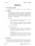
1.
There is little danger of electrical shock from the dc output of thispower supply. However, there are several other
possible test conditions using this power supply that can create a high voltage shock hazard:
a.
If the equipment under test is the "hot chassisn type, a serious shock hazard exists uniess the equipment is unplugged (just turning off the equipment does not remove the hazard), or the precautions of step 8 a:e observed.
If the equipment under test is "powered up" (and that equipment uses high voltage in aay of its circuits), the
b.
power supply outputs may be floated to the potential at the point of connection. Remember that high voltage
may appea-r at unexpected points in defective equipment.
Do not float the power supply output to more than
500 volts peak with respect to chassis or earth ground,
c.
If the equipment under test is "off" (and that equipment uses high voltage in any of its circuits under normal
operation), discharge high-voltage capacitors before
voltage long after the equipment is tr:rned of f.
Z.
making
connections
or tests.
Some circuits
retain
Use only a polarized 3-wire ac outlet.
This assures that the power supply chassis, case, and ground terminal
connected to a good earth ground and reduces danger from electrical shock.
(continued on inside back cover)
high
are
InstructionManual
for
Model
1635
DC POWERSUPPLY
With LED Display
trlYNASCAN
COF|POF|ATIC)N
6460WestCortland Street
Chicaso,Illinois60635
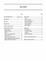
TABLE OF CONTENTS
Page
TESTINSTRUMENT SAFETY.....
inside front cover
INTRODUCTTON....
......1
FEATURES.
.......2
S P E C I F I C A T I O N S. .
......
CONTROLS AND INDICATORS .
.....
.3
.....5
.?
OPERATING INSTRUCTIONS....
........
S a f e t y P r e c a u t i o n s. .
...........?
E q u i p m e n tP r e c a u t i o n s .
.........7
Hook-Up
........7
Typical ConstantVoltage Operation
...........10
S e t t i n gC u n e n t L i m i t . .
........12
TypicalConstantCurrentOperation
...........12
Constant Voltage/Constant Curent Characteristic .....13
Using The External Voltmeter Function
........14
Page
APPLICATIONS....
General
E l e c t r o n i c sS e r v i c i n g
E l e c t r o n i c sM a n u f a c t u r i n g . . . . . .
E l e c t r o n i c sD e s i g n L a b . . .
E l e c t r o n i c sE d u c a t i o n .
Battery Charging.
......1?
........1?
..........17
.......17
......18
.,..,....18
......18
MAINTENANCE...
F u s eR e p l a c e m e n t . .
Line Voltage Conversion
Adjustments
I n s t r u m e n tR e p a i r S e r v i c e . . . . .
......I9
...........f
9
.......19
...........19
........22
W A R R A N T Y S E R V I C E I N S T R U C T T O N S. . . .
LIMITED ONE-YEAR WARRANTY
..,...23
.......24
INTRODUCTION
The B & K-hecision
Model 1635 DC Power Supply is a
high quality, general purpose dc power source. It provides
0-30 volts dc output, adjustable with both coarse and fine voltage controls for precise settabiiity.
The current output is
0-3 amps. A three station pushbutton assembly allows the
Iarge panel-mounted LED meter dispiay to monitors either
the output current, output voltage, or a voltage (up to 199.9
volts) applied to the external metering inputs. LED's indicate
voltage or current metering.
The Model 1635 exhibits excellent regulation ard low
The circuit design incorporates a preripple characteristics.
regulator, which greatly reduces internal power dissipation at
low output voltages. The styling is both attractive and functional.
The mechanical configuration conserves bench space
and allows for easy portability.
This instrument
may be used in constant voltage or
constant current applications.
The crossover from constant
voltage to constant current modes is smooth arld automatic.
LED's indicate the nCV" (constant voltage) or nCCn (constant
current) mode of operation.
In constant voltage applications,
a current limit may be preset.
When load variations cause
the current to reach the preset limit. the unit then resulates
output current rather than output voltage. Current limits a.re
adjustable from 570 to 100% of maximum. In constant current applications, the maximum voltage may be preset. When
load variations cause current to drop below the regulated
value, the unit reverts to regulated voltage operation at the
preset value.
Reverse polarity protection prevents accidental damage
to the power supply from improper connection to an external
voltage, and current limiting protects the equipment being
powered, as weli as the power supply.
The output is isolated from chassis and earth ground,
which permits full flexibility of connections. When needed,
ttre (+) or (-) polarity may be strapped to ground, or either
polarity may be floated to an external voltage, Two supplies
may be connected in series as a 0-to-60 volt power soulce, or
two supplies may be connected in parallel, with suitable
balancing resistors, for up to twice the output current.
This power supply is well suited for a wide variety of
electrical
and eiectronics applications, including service
shops, engineering labs, production testing, school laboratories, and home use by hobbyists.
FEATURES
(F3O VOLTS
Continuously variable
and fine controls.
over 0-to-30
volt range with coarse
(F3 AMPS
0-to-3 amp current rated for continuous duty at full output
curent'
I-ABoRAToRY
QUArrrY
Excellent requlation, Iow ripple.
CONSTANT CURRENT
CONSTANTVOLTAGEOR
Provides regulated dc voltage output or regulated
rent output. Crossover is smooth ald automatic.
dc cur-
LED DISpLAy
A large, easy-to-read LED 3-1/Z digit display monitors
or an external voltage aad
output voltage, output curent,
provides good visiblitty in bright or low light. Meter allows
resolution of 0.1 volt or 0.1 amp.
EXTERNAL VoLTMETER FUNCTTON
Front panel input jacks allow built in meter to be used to
measure external DC voltages of up 199.9 volts.
LED INDICATORS
Act as pilot light
metering.
PRE-REGULATOR
Limits internal
and identify
mode
of
operation
and
dissipation for higher reliability.
$OLATED
ourPUT
Either poiarity may be floated or grounded'
OVERLOAD 'ROTECTION
F u l l y a d j u s t a b l e c u r r e n t l i m i t i n g ( f r o m 5 q ' o t o 1 0 0 9 / oo f
maximum output current) protects circuit pnder test and
the power supply.
RE\rERSE POLARITY PROTECTION
Prevents damage to power supply from erternal voltage of
reverse polarity'
"STYLING
^:,:
Modern functionai styling'
s p a c e a r r r da i d s p o r t a b i l i t y .
c'ntrols'
configuration conserves bench
Logical, convenient layout of
HOOK-UP CABLES
Supplied with red and black hook-up leads.
SPECIFICATIONS
0 to 30 VDC, coarse ard fine
OUTPUTVOLTAGE:
^ l:..^.^duJ
urrrrrErr
CONSTANT
VOLTAGE
Recovery Time:
<200 tE typicai.
Ripple Voltage
Peak-to-Peak:
RMS:
<Z mV.
<1 mV.
Temperature Coef f icient
(0o to +35o C):
5 mV/o C typical.
CURRENT
Type:
3-1lZ d\eit LED Display
0.5" high.
Functions:
Volts, Amps, External Volts.
OPERAfiON
Voltage Regulation
-0.020^ + 2 mV.
Line (110-130V):
L o a d ( n o l o a d t o f u l l l o a d ) : < 0 . 0 2 9 7 0+ 3 m V .
CONSTANT
s3 mA typical.
METERING
0 to 3 A.
OUTPUT CURRENT:
Current Ripple:
.
Lr
OPERATION
Adjustable Current Limits:
5 o / ot o 7 0 0 V o( 0 . 1 5 A t o 3 A ) .
Current Regulation
L i n e ( 11 0 - 1 3 0 \ 4 :
Load
<5 mA typ,
<5 mA t1p,
9 mA max.
9 mA max,
Voltm eter
Ralge:
Accuracy:
0 t o 1 9 9 . 9V .
t(0.5%+2digits).
Ammeter
Rarge:
Accuracy:
0 t o 1 9 . 9 9A .
!(O,5%+Zdigits).
POWER REQIIIREMENTS:
110/120/220/240vAC tljTo,
5 0 / 6 0H z .
POWER CONSUMPfiON:
Approximately 175 W or iess
at full load.
PROTECTION:
Reverse polarity protection,
Current limiting.
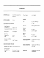
SPECIFICATIONS
TEMPERATURE RANGE
Operation:
Storage:
DruENSIONS (IIx\f,xD):
WEIGIIT:
1 1 - 1 / 4l b .
ACCESSORIES SUPPI-IED:
Hook-Up Leads, 1 red, I black.
Spare Fuse.
Schematic Diagram &
Parts List.
0o to +40o C.
-150 to +70oc.
I7Z x 119 x 305 mm.
6.75x4.69x12".
CONTROLS
INDICATORS
7.
Either the uCCu or "CV" and
or "A" indicators will
be lit whenever the unit is operating, thus serving as a pilot
light.
The unit automatically
changes from CV to CC
operation when the preset current limit is reached.
1.
IndicatorC.C. (Constmt Curent)
Red LED lights in
constant current mode. Unit regulates output current
at value set bl' CURRENT controls.
Z.
C.V. (Constant Voltage) Indicator.
Green LED lights in
constant voltage mode. Unit regulates output voltage
at value set by VOLTAGE controls.
3.
4.
5.
EINE Control. Fine adjustment of output voltage" Read
value on LED display when volt meter (\4 function is
selected.
CURRENT
8.
POWER CONTROLS
9.
ON-OFF
10.
V (Volt Meter) Indicator.
Green LED iights rvhen the
internal or external voltage metering mode is selected.
METERING
A (Crnrent Meter) Indicator.
Green LED
current metering (A) mode is selected.
liehts
when
Switch.
OUTPUT TERMINALS
r+'Terminal. (Red). Positive polarity output terminal.
11.
72.
GND Terminal (Green). Earth and chassis ground.
"-" Terminal (Black). Negative polarity output terminal.
SELECTION
SWITCHES
13.
When this switch
A Pushbutton.
Display indicates output current.
14.
V Pushbutton.
When this switch is engaged, the LED
Display indicates the output voltage,
15.
VOLT
METER
Rrshbutton.
EXTERNAL
When this
switch is engaged, the LED Display indicates the dc
voltage applied to the EXTERNAL VOLT METER Jacks.
CONTROLS
COARSE Control- Coarse adjustment of output voltage"
Read value on LED display when volt meter (\4 fr:nction
is selected,
CONTROL
Adjusts current limit in constant
CURRENT Coattol.
voltage mode.
Adjusts constant current value in
constant current rnode. Current can be read from LED
display when curent meter (A) function is selected.
LED Display. 3-1lZ digit display indicates internal voltage, internal current, or dc voltage applied to EXTERNAL VOLT METER jacks (depending on which meter
selection srvitch is engaged). External DC voltage up to
199.9 volts can be read on the rlisplay.
VOLTAGE
6.
AND INDICATORS
is engaged, the LED
CONTROLS
AND INDICATORS
15.
V Jack. Positive input jack for external DC voltmeter
function. Maximum input is 200 VDC.
17.
Common (ground) jack for external IJC
COM Jack.
Potential at this jack should not
voltmeter function.
exceed 100 VDC above ground.
REAR PANEL
CONTROLS
18.
Fuse.
19.
Power Cord-
1
't5
14
13
Fig. 1. Front Panel Controls and Indicators.
Fig. 2. Rear Panel.
OPERATING INSTRUCTIONS
SAFETY
PRECAUTIONS
{Jse only a polarized 3-wire ac outlet.
This assures that
the power supply chassis, case, and ground terminal
are
connected to a good earth ground ard reduces danger from
electrical shock.
There is little dalger of electrical shock from the power
supply output, which produces a maximum of 30 volts dc.
However, therc mey be great danger of electncal shock if the
power supply output is connected. to an extemalhigh wltage.
Some equipment being powered may contain high voltage and
present a shock hazard. Observe caution. If the power supply
output is floated (referenced to a voltage rather than earth
ground) tr:rn off the power supply ond the equipment wlder
test when making connections. Never float the power supply
to a potential greater than 100 volts peak with respect to
earth ground.
EQTIIPMENT
such protection. Always carefully observe polarity; incorrect
polarity may damage the equipment under test.
Do not exceed the voltage rating of the circuit being
powered. Many transistors and integrated circuits will not
withstand voltage of 30 volts.
There is no need to worry about voltage spikes or overThe voltage beshoot damaging the equipment under test.
tween the output terminals of the power supply never exceeds
the preset value as the POWER switch is turned on or off.
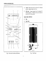
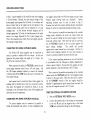
EOOK.UP
1.
Turn off the power supply
powered during hook-up.
Z.
Connect the positive polarity of the device being powered to the red (+) terminal of the power supply.
3.
Connect the negative polarity of the device being
powered to the black (-) terminal of the power supply.
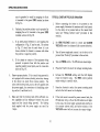
4.
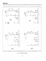
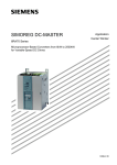
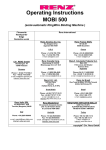
Fig. 3 illustrates the grormding possibilities.
PRECAUTIONS
Avoid using the power supply in ambient temperatures
above +40o C, Aiways allow sufficient air space aror:ad the
heat sink at the rear of the power supply for effective radiation to prevent internal heat build-up.
Although the power supply is protected against reverse
polarity damage, the circuit being powered may not include
a.
and the
equipment
to be
If the negative polarity of the equipment or circuit
being powered is also the chassis or common, it
INSTRUCTIONS
OPERATING
D C P O W E RS U e e r Vt e : S - I
I
- -
-
, ..i, r
!l !l L.l
ffiiAL
votr vriin
-'
l
i-lo
, i , i
l i l
l
:
pment
Equr
Powered
Bernq
D O
I
_-_1
\
,,
Strap
l=.
:,',,,,,,:'!
t=
Hot
A .*
u/rtr
B.rfz Grounded.
common
p0srlrve
D0anIy.
co
n rth
Grouncte
dm
. m ow
ve polaritv
neqal
F i g , 3 ( A a n d B l . Grounding Possibilities.
8
L-
OPERATING
INSTRUCTIONS
DC POWER SUPPLY1635
.i
-
ll fl
E X I E F N A L V O L TM E T E F
,cirr o.
,!
NI
!ilTAGL
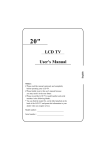
E ou r pm en t
BerngPowered
No Strap
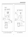
C.No groundreference
D. t
nol commonwith
Grounded.
negatrve
or Positive
Polarit\/
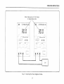
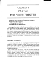
Fig. 3 (C and D). Grounding Possibilities.
9
OPERATING
INSTRUCTIONS
may be grounded to earth by strapping the black
(-) terminal to the green (GND) terminal as shown
in Fig. 3A.
b.
Similarly, the positive polarity can be grounded by
strapping the red (+) terminal to the green (GND)
terminal as shown in Fig. 3B.
c.
If an earth ground reference is not required, the
configuration of Fig. 3C may be used. The scheme
in Fig. 3C should also be used where it is not
known whether the chassis is common with either
the positive or negative polarity.
d.
TYPICAL
If the chassis or common of the equipment being
powered is separate from both the positive and
negative polarity power inputs, use the connection
shown in Fig. 3D.
Observe proper polarity. If the circuit being powered is
not equipped with reverse polarity protection, damage
to the circuit can result from reverse polarity.
Use
color coded hook-up leads, such as the set supplied with
the power supply, for convenience in identifying polarity, red for (+) and black for (-).
Make sure that
rent capability
supply arrd the
leads supplied
3 amps,
the hook-up leads offer sufficient curand low resistance between the power
circuits being powered.
The hook-up
with the power supply are rated for
l0
CONSTANT
VOLTAGE
OPERATION
1.
Before connecting the device to be powered to the
power supply, determine the maximum safe load cr.rrrent
for the device to be powered and set the cunent limit
value (see'Setting
Current Limit" procedure in this
section).
2.
Set FINE
VOLTAGE
3.
Turn off power supply and connect it to the device to be
powered (see "Hook-Up" procedure in this section).
1.
Turn on PCIWER switch.
5.
Press the V switch to select the voltage metering mode.
6.
Increase the VOLTAGE setting until the LED display
reads the desired value,
The EINE control permits
easier setting to a specific value,
7.
Press the A switch to select the current metering mode
and note the load current on the displav.
8.
If the load current exceeds the preset current limit, the
CV indicator will go of f and the CC indiiator will light.
In this case, the power supply automatically switches to
the constant current mode, and further rotation of the
VOLTAGE control wiIl not increase the output voltage.
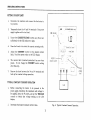
VOLTAGE control
control to minimum
to center and COARSE
(fully counterclockwise).
The CVindicator
should light.
OPERATING
CVindicatoron
-.. .r.DCpowensuppr-ilo:il
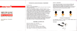
Fig.4.
Typical Constant Voltage Operation.
Fig. 5. Setting Current Limit.
INSTRUCTIONS
OPERATING
INSTRUCTIONS
SETTING CURRENT
I.IMIT
i"
Determine the maximum safe current for the device to
be powered.
Z.
Temporarily short the (+) and (-) terminals
supply together with a test lead.
3.
Rotate the COARSE VOLTAGE control awav from zero
sufficiently for the CC indicator to light.
4.
Press the A switch to select the current metering mode.
5.
Adjust the CURRENT control for the desired current
limit. Read the cunent value on the LED display.
6.
The current limit (overload protection) has now been
preset.
Do not change the CURRENT control setting
after this step.
7.
Remove the short between the (+) and (-) terminals
hook up for constant voltage operation.
TYPICAL
CONSTANT
CURRENT
of the power
I t-,
,.L'
Adlustto
0esrren
currenl
Preset
voltage
and
ilmrT
OPERATION
1.
Before connecting the device to be powered to the
power supply, determine the maximum safe voltage to
be applied, press the V switch, and set the VOLTAGE
controls to obtain that voltage reading on the LED
display.
Z.
Determine
the desired constant cr.rrrent value.
Fig.6.
tz
Typicai Constant Current Operation.
OPERATING
Set the CURRENT
clockwise).
A
control
to minimum
(fully counter-
supply.
The CC indicator
should
6.
Press the A switch to obtain the current metering mode.
1
Increase the CURRENT control setting until the desired
constant current value is read on the display, or set the
cunent limit in advmce (before connecting the load) as
"Setting
prescribed in the earlier
Current Limit"
procedure
6.
For example, if the load is such that the power supply is
operating in the constant voltage mode, a regulated output
voltage is provided. The output voltage remains constant as
the load increases, up until the point where the preset current
limit is reached. At that point, the output current becomes
constant and the outplrt voltage drops in proportion to further
increases in load. The crossover point is indicated by the
front panel LEI) indicators. The crossover point is reached
when the CV indicator goes off and the CC indicator comes
on.
Turn off the power supply and connect it to the device
to be powered.
Turn on the power
Iight.
I
4
r
i
If the load current drops below the constant current
value, the CC indicator will go off and the CV indicator
will light. In this case, the power supply automatically
switches to the constant voltage mode, and further
rotation of the CURRENT control will not increase the
output current.
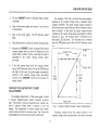
CONSTANT VOLTAGE/CONSTANT
CHARACTERISTIC
INSTRUCTIONS
llonsl2nt
nr rrrpnl
Hange
Vo MAX
I
lo Max
li
tI
I
Constanl
Voltaqe
Ranqe
0utput
Voltage
CURRENT
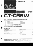
The working characteristic of this power supply is calied
a constant voltage/constant
current automatic crossover
type. This permits continuous transition from constant current to constant voltage modes in response to the load
change. The intersection of constant voltage ard constant
current modes is called the crossover point. Fig. ? shorvs the
relationship between this crossover point and the load.
0utputCurrenl
Fig. 7.
Constant
Voltage/Constant
I
Curent
Characteristic,
Similarlv. crossover from the constant current to the
constant voltage mode automatically occurs from a decrease
1.)
OPERATING
INSTRUCTIONS
in load. A good example of this would be seen when charging
Initially, the open circuit voltage of the
a lZ-volt battery.
power supply may be preset for 13.8 volts. A low battery will
place a heavy load on the supply and it will operate in the
constant cunent mode, which may be adjusted for a 1 amp
As the battery becomes charged, and its
charging rate.
voltage approaches 13.8 volts, its load decreases to the point
where it no longer demands the full 1 amp charging rate.
This is the crossover point where the power supply goes into
the constant voltage mode.
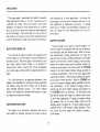
CONNECTING
two supplies wili provide trvo 0-30 volt output at up to 6 amps
(heavier gauge hook-up leads are advisable).
Current
equalizing resistors must be used as shown in Fig. 9.
I{owever, the protective current limiting featr.re will prevent
damage if current is temporarily unbalalced during set-up.
When connected in parallel and operating in the constant
voltage mode, determine the total load current limit ald
preset the current limiting for each porver supply to half the
total load current value. Then when the load is connected,
set the VOLTAGE controls on the two power supplies for
also provide
This
should
readings.
voltage
equal
approximately equal current from each supply. Add the two
current meter readings together for total load current, or
connect an external ammeter in series with the load.
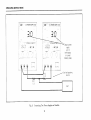
TWO POWER SUPPLIES IN SERIES
Two Model 1635 power supplies may be connected in
In this conseries to provide a variable 0-60 volt output.
fig'.rration the power supply can supply up to 3 amps. See
Fig. 8 for the connection scheme.
If the current equalizing resistors are not well matched,
it is preferable that the voltages be slightly unbalanced to
achieve current balance, Be sure that the supplies are adequately balanced so that both remain in the CV mode.
When connected in series, the VOLTAGE controls of each
power supply exercise control over a 0-30 volt range. Add
the LED display readings together or connect the external
voltmeter jacks (V and COM) across the load to determine the
total output voltage.
When connected in parallel aad operating in the constant
curent mode, the VOLTAGE controls of both supplies should
be preset to the same value. Then when the load is connected, the CURRENT controls of the two supplies should be
adjusted for approximately equal current from each unit. Be
sure that both supplies remain in the CC mode.
Load current may be monitored from either supply; the
readings wiil be identical since they are connected in series.
Also, since the supplies are connected in series, it is only
necessary to set the current limit on one of the supplies; the
other may be set for maximum.
CONNECTING
USING TTIE EXTERNAL
I4
FUNCTION
VOLT METER switch.
1.
Z.
Connect the positive side of the voltage to be measured
to the red (9 jact< a.rrd the negative side to the black
(COM) jack and read the voltage on the LED display.
TWO POWER SUPPIJES IN PARALLEL
Two power supplies may be connected in parallel to
In this confieuration the
double the maximum load cunent.
VOLTMETER
Press the EXTERNAL
OPERATING
0utput
voltage
equals
sumof bothdrsplays
(involtage
metering
mode)
Fig. 8. Connecting Two Power Supplies in Series.
15
INSTRUCTIONS
OPERATING
INSTRUCTIONS
a o e
1o
_,---
Fig. 9. Connecting Two Power Supplies in Parallel.
lo
U s P r o d dP q ul l ' / n n
t p (| . , a , \
APPLICATIONS
GENERAL
with 1Z-volt electrical systems. Some trucks use a Z4-volt
electricai systemi bench testing of equipment from these
svstems should be performed at Z8 voit.s.
The Model 1635 power supply has a very rvide variety of
applications in electrical
and electronics servrcing, engineering laboratories, manufacturing and testing facilities,
schools, and home hobbying. The porver supplv output is fullv
adjustable from 0 to 30 volts arcl 0 to 3 amps. This flexibility
makes them suitable for most applications requiring a dc
power soutce.
ELECTROMCS
Somc serrricing applications require the iniection of a
variable dc voltage for certain tests, such as -hecking the
effect of AGC bias in a television receiver, Ihis r'-'luircs.rn
The
i s o l a t e d d c p o w e r s u p p l v , s u c h a - s t h e M o d e l 1 6 35 .
equipment being tested may contain its own power supplv and
operate from ac power. A dc voltage may already be present
One polarity of the power supplv output is
in the circuit.
floated to an appropriate point in the circuit, such as the
The other polarity of the power
emitter of a transistor.
supply output is then applied to another point in the circuit,
such as the base of that transistor. Varying the power supply
voltage then varies the dc bias on the stage. md the effects
A series limitine resistor is oftt:n used to
may be noted.
protect the circuits from overdissipation.
SERVICING
N{ost electronics troubleshooting and repair is performed
on a test bench. This power supply can provide the dc porver
source to operate a module or circuit board on the test bench
when it is removed from its parent equipment. It can be used
to power portable, battery-operated equipment and check the
effect of low battery voltage. It can power vehicular equipment such as tape players, auto sound systerns, CB radios,
etc. on the test bench.
ELECTROMCS
MANUFACTURING
In electronics manufacturing facilities, the power supply is
often used m a dc power source while testing and adjusting
modules. subassemblies, and complete units in the production
and assembly area or in the qualitv control area. The instrument can be used in incoming inspection as a dc power source
for testing purchased components and subassemblies.
Most automobiles and other vechicles use 1Z-volt electrical systems.
Although the eiectrical svstem is normally
referred to as a 1Z-volt system, actual battery voltage rvhen
fully charged is approximately 14 volts. The power supply
mav be set to 14 volts for servicing equipment from vehicles
l?
APPIJCATIONS
This power supply is particularly well suited for manufacturing applications because of its ease of operation and its
When ioad cunent or total power
continuous duty rating.
dissipation are among the main characteristics to be measured, the total load current and voltage are easily displayed
on the LED display. The current limit can be set so that all
units which do not meet the load current specification will
cause the CC indicator to light, and the unit can be rejected,
ELECTRONICS
In addition, the
ously described for all other applications.
power supply can be used in the classroom laboratory to conIn learning
duct experiments in fundamental electronics'
Ohm's law, for example, the relationships of resistance' current, and voltage are easilv demonstrated by the use of a
power supply.
BATTERY
The power supply can be used as a battery charge! to restore the charge in rechargeable batteries such as lead-acid,
nickel-cadmium, and some alkaline types. Refer to the batfor proper volcharging specifications
tery manufacturer's
tage and current settings, Charging information is sometimes
printed on the batteries. Battery charging, at ieast initiallyt
requires the constant current mode of operation. Before connecting the power supply to the battery, preset the VOLTAGE
controls to the fully charged terminal voltage specified by
Turn off the power supply while
the battery manufacturer.
Observe Proper polarity and connect
connecting the battery.
as for constant current operation. Adjust the CURRENT control for the maximum charging current specified by the bat(If the maximum charging current is
tery manufacturer.
greater than the power supply's maximum load current, set
The CC indicator will
the CURRENT control to maximum).
light arrd the battery will charge at the preset current limit'
As the battery approaches full charge, its terminal voltage
will approach that of the power supply output and the
charging current will taper off. The power supply may automatically switch to CV (constant voltage) operation. When
this occurs, the power supply will continue to provide a
trickle charge,
DESIGN LAB
The technician or engineer working in al engineering laboratory requires a dc power supply to power breadboard and
protot)?e circuits. This power supply is ideai because it monoutput voltage, or an external DC
itors output cunent,
voltage, limits current to protect the circuit, is adjustable
over a wide range, and has excellent requlation and very low
ripple.
Use of the instrument in an engineering laboratory is very
similar to that described for servicing electronics equipment
and modules, except that lower currents may be prevalent
The current limiting
circuits.
when powering individual
feature is very valuable in this application because it can protect unproven circuits from damage.
ELECTRONICS
CIIARGING
EDUCATION
curriculum
may use the
The student in an electronics
power supply for powering equipment and circuits as previ-
l8
MAINTENANCE
are. for tse by qualified
instructions
The following
personnel only. To avoid electrtcal shockt do not per'
form any seruicing other than contained in the operqting
nistructtons unless you are qualified to do so.
FUSE REPLACEMENT
If the fuse blows, the CVr CC, V, or A indicators rvill not
light and the power supply will not operate. The fuse shorrld
not normally open unless a problem has developed in the
unit. Try to determine a:nd correct the cause of the blown
fuse, then replace only with a fuse of the correct rating. For
110 or 220 V operation a 3 A, 250 V fuse should be used and
f.or 220 ot 240 V operation a 1.5 A, 250 V fuse should be
used. The fuse is located on the reat panel (see Fig. 2).
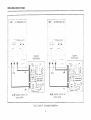
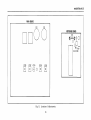
LINE VOLTAGE
1.
Make swe the power cord is unplugged.
Z.
Remove the case ald locate the porver transformer.
3.
Rewire the power transformer to the desired line voltage as shown in Fig. 10. Insulate the ends of the unused
transformer tap wires.
4.
A change in line voltage may also require a corresponding change of fuse va1ue. Install the correct fuse value
as listed in the FUSE REPLACEMENT section.
5,
Replace the cover.
6.
Affix a label showing the correct line voltage and fuse
value (if changed) for the unit after conversion. Place
this label directly over the factory label.
ADJUSTMENTS
This rmit was accurately adjusted at the factory before
shipment. Readjustment is recommended only if repairs have
been made in a circuit affecting adjustment accuracy, or if
you have a reason to believe the unit is out of adjustment.
However, adjustments should be attempted only if a multimeter with m accuracy of J0.1% dcv or better is avaiiable
(B & K-Precision Model 2817 or equivalent).
CONVERSION
The primary rvinding of the power transformer is tapped to
p e r m i t o p e r a t i o n f r o m 1 1 0 ' 1 2 0 ' 2 2 0 , o t Z ' 1 0V A C ' 5 0 / 6 0 H z
line voltage. Conversion from one line voltage to another is
done by a simple wiring change as shown in Fig. 10.
A label on the rear panel identifies the line voltage to
which the unit was factory wired. To convert to a different
line voltage, perform the foilowing procedure:
If readjustment is required' use the following procedure.
Locations of the adjustments are shown in Fig. 11.
19
MAINTENANCE
s101
F101
T10
T101
sl01
120 V
rL
L
r
r-
1 1 0V
. *tneruur
-!
iL
T101
s101
F101
BLK
____
_-tt_-__<r/
T -r---t
'tr-[-r
-
TAN
-- .+ IAN
oRG
r20v
GRAY 11OV
tar
rI
F-
iFIL
240 V
220 V
F i g . 1 0 . Line Voltage
z0
Conversion.
MAINTENANCE
MAINBOARD
c102
rroo
METERING
BOARD
r!t--E--J'lr
7I-lP
S n
e \-/
o / 1
[l \-i
v vR201
a---------D
VR108 VR1O7VB1O5
@
VR1O6 VR1
04
t r @ o t rtr
Fig. f1.
Location of Adjustments.
zl
MAINTENANCE
1.
)
Connect an accurate G0,l%) external multimeter to
me€rsure the dc voltage at output terminals of the power
supply.
Set the COARSE and EINE VOLTAGE
mum (fully cotrnterclockwise).
Adjust trimmer
the multimeter.
9.
Turn the COARSE
and EINE
maximum (fully clockwise).
VOLTAGE
controls
to
Adjust trimmer pot VRl04 for a reading of 31.5 volts on
the multimeter.
6,
With the V switch on the power supplv engaged, adjust
VRZ01 for a reading of 31.5 on the LED display.
7
Set the CURRENT
clockwise).
control to minimum
arrd FINE
VOLTAGE
controls
to
a
pot VRIO? for a reading of 0 amps on
10.
Adjust trimmer
the multimeter.
1i.
Turn the CURRENT control to max (fully clockwise).
12.
Adjust trimmer pot VRl06 for a reading of 3.15 amps on
the multimeter.
13.
With the A switch on the power supply engaged, adjust
VRl08 for a reading of 3.15 on the LED display.
controls to mini-
pot VR105 for a reading of 0 volts on
Set the COARSE
centered position.
INSTRUMENT
REPAIR
SERVICE
Because of the specialized skills and test equipment required for instrument repair and calibration, manv customers
prefer to rely upon B & K-hecisioD
for this service.
We
maintain a network of B & K-Precision authorized service
agencies for this purpose. To use this service, even if the instrument is no longer under warranty, follow the instructions
given in the WARRANTY
SERVICE INSTRUCTIONS
section
of this manual There is a nominal charge for instruments out
of warrantv.
(fullv counter-
Connect the external multimeter to measure dc crlrrent
at the output terminals of the power supply. Select a
current range capable of measuring at least 3.2 amps.
zz
ITARRANTY
SERVICE INSTRUCTIONS
(For U,S.A. and its Overseas Territories)
1.
Refer to the MAINTENANCE
applicable.
Z.
If the above-mentioned does not correct the problem Jrou are experiencing with your unit, pack it securely
(preferably in the original carton or double-packed).
Enciose a letter describing the problem and include your
name and address. Deliver to, or ship PREPAID (UPS preferred in tl,S.A.) to the nearest B & K-Precision
authorized service agencv (see list enclosed with unit).
section of vour B & K-hecisioa
If your list of authorized B & K-Precision
vour nearest service agencvr or write to:
instruction
service agencies has been misplaced,
manual for adiustments that mav be
contact
B & K-hecision,
Dlmascan Corporation
Factory Service Operations
6460 West Cortland Street
C h i c a g o , I l l i n o i s 6 0 6 35
Tel (312)889-8870
Telex: Z5-3475
Also use this address for technical inquiries
and replacement parts orders.
your distributor
for the name of
IJMITED ONE.YEAR WARRANTY
DYNASCAN CORPORATION
warrants to the original purchaser that its B & K-hecision
product, and the component
parts thereof, will be free from defects in workmanship and materials for a period of one year from the date of purchase.
DYNASCAN will, without charge, repair or replace, at its option, defective product or component parts upon delivery
to an authorized B & K-Precision service contractor or the factory service department, accompanied by proof of the
purchase date in the form of a sales receipt.
To obtain warranty coverage in the U.S.A., this product must be registered by completing and mailing the enclosed
card to DYNASCAN,
wananty
registration
B & K-hecision,
6460 West Cortland Street, Chicago, Illinois 60635 within
fifteen (15) days from the date of purchase.
Erclusions: This ruorronty does not opply rn the event of misuse or abuse of the product or os c result of wlauthorized
Itisvotdif
oltemtionsorrepoirs.
theserialnumber isoltered, defacedorremored.
DYNASCAN shall not be liable for any consequential damages, including without limitation damages resulting from loss
of use. Some states do not allow limitation of incidental or consequential damages, so the above limitation or exclusion
may not apply to you.
This wananty
gives you specific rights and you may also have other rights which vary from state to state.
For your convenience we suggest you contact your B & K-hecision
distributor, who may be authorized to make repairs
or can refer you to the nearest service contractor. If warranty service cannot be obtained locally, please send the unit to
B & K-hecision
Service Department, 6460 West Cortland Street, Chicago, Illinois 60635, properly packaged tn avoid
damage in shipment.
B & K-Precision Test Instruments warrants products sold only in the U,S.A. and its overseas territories.
products which it sells.
countries, each distributor warrants the B & K-hecision
AA
In other
NOTES
NOTES
TEST INSTRUMENT SAFETY
(continued from inside front cover)
3.
Don't expose high voltage needlessly. Remove housings and covers only when necessary. Turn off equipment
making test connections in high-voltage circuits. Discharge high-voltage capacitors after removing power.
4.
If possible, familiarize yourself with the equipment being tested and the location of its high voltage points.
remember that high voltage may appear at unexpected points in defective equipment.
5.
Use an insulated floor material or a large, insulated floor mat to stand on, and an insulated work surface on which to
place equipmentl and make certain such surfaces are not damp or wet.
6.
Use the time-proven "one hand in the pocketn technique while handling an instrument probe.
to avoid contacting a nearby metal object that could provide a good ground return path.
7
When testing ac powered equipment, remember that ac line voltage is usually present on some power input circuits
such its the on-off switch, fuses, power transformer, etc. any time the equipment is connected to an ac outlet, even if
the equipment is turned off.
Be particularly
while
However,
careful
Some equipment with a two-wire ac power cord, including some with polarized power plugs, is the "hot chassisn type.
This includes most recent television receivers and audio equipment. A plastic or wooden cabinet insulates the chassis
to protect the customer.
When the cabinet is removed for servicing, a serious shock hazard exists if the chassis is
touched. Not only does this present a dangerous shock hazard, but damage to test instruments or the equipment under
test may result from connecting an earth gror:nd lead of a test instrument to a nhot chassis". To make measurements
in 'hot chassis" equipment, always connect an isolation transformer between the ac outlet and the equipment under
test. The B & K-hecision
Model TR-l10 or 1604 Isolation Transformer, or Model 1653 or 1655 AC Power Supply is
suitable for most applications. To be on the safe side, treat all two-wire ac powered equipment as "hot chassis" unless
you €rre sure it has an isolated chassis or an earth ground chassis.
Never work alone. Someone should be nearby to render aid if necessary.
tation) first aid is highly recommended.
Training in CPR (cardio-pulmonary
resusci-
DYNASCAN
CORPOF|ATION
6460 West Cortland Street
Chicago,Illinois 60635
O 1986 o DYNASCAN CORP.
480-535-9-001
Printed in U.S.A.