1
CIVIL & ENVIRONMENTAL ENGINEERING
MANUALS
Instrumentation.
eb.30.10.02
NSE.L
CUtr.E
UWUC
Linear VariableDifferentialTransformers:
Theorv.Instrumentation
andInstallation
Prepared
by: Grzes.otzBanas and Can Simsrr
Sponsored
by: Newmark StructuralEngineeringLaboratory
Departmentof Civil & Environ. Engineering
Collegeof Engineering
Universityof Illinoisat Urbana-Charnpaign
U r b a n aI,l l i n o i s6 1 8 0 1 - 2 3 9 7
October,2002
INTRoDUCTIoN
The purposeof this rnanualis to provide the basic principlesof theory and installation
associatedrvith linear variable diffcrcntial transfbrmersto users of the Nervmark Structural
EngineeringLaboratory(NSEL). The materialpresentedin this manualis basedon 50 yearsof'
ofpast
listedat the endof thisnranual.Also, the experience
expcrience
ofNSI:L and ret'erences
qucstions
have
askcd
on
Many
been
*as
u,hile
working
on
this
manual.
usersol'NSEL
used
wererecomrrendedin rvhichansu'crscould
rlhich eitlierdirectansu'ersrveregivcn or ref-erences
fon.nat. Any
be tbund. That is w'hy this manualwas partially rvrittenin thc question-ansu'er
criticalcommentsand remarksof currentuscrsare also welcomcdand they rvill be usedin a
and
future revision. This manual is divided into threc scctions:Theory, lnstrumentation,
Installation.
I HEORY
What is a lincar variabledit-ferential
transforrner?The linear variablc dill'erential
of
rvhich allolvs the measurement
transducer,
transfbrmer(LVDT) is an elcctromcchanical
displacernent
of any movablepafi. The measuredamountof displacementis proportionalto the
elcctricaloutput of the transduceras a resultantof an inductiveinteractionbetrvccna magnetic
core and a set of windings: prinraryrvindingwhich is polveredby high frequencylorv voltage
'fhc
current,and trvo secondaryrvindingsusuallysymrnetricallylocatedagainstthe primary one.
secondarywindingsgeneratethc electricaloutputcorrelatedto the positlonof the magncticcore.
Figure I shorvsan examplcof a commonlyusedLVDT. The primary rvinding (8) and
the secondaryu,indings(9) are separated
by high-densityglossfilled polyrnercoil fbrm (4) and
'fhis
in cpoxy (3).
assemblyis covcrcdby stainlesssteelhousing(l),
both are encapsulatcd
sleeve(6), and end caps(5). The h igh-pcrneabilitymagneticshell (2) is placedbetweenthc
'l'he
(3), and separators
(zl).
nickelhigh-permeability
housing(l), and polyrnerencapsulation
(6).
sleeve
Carricr(10),
(7),
is
placed
inside
of
the
usuallythreadedfiom both ends,
iron core
rvhich must bc non-magnetic,
transfersthe linear motion of an object to the core (7) and
changestlie electricaloutputof the [-VDT.
consequently
Horv doesthe I-VDT work? Figure2 illustrateswhat happcnsrvhenthe core of'the
by a
LVDT is in differentaxialpositions.The primaryrvinding,(P) o1'theLVDT is energized
(AC)
is
coupled
by
source.The magneticflux thus developed
constantamplitudcalteredcurrent
(Sr) and (Sz). If the core is locatcdmidivay
tlie core to the adjaccntsecondaryr.vindings,
(S1) and (S2)(Figure2b), equalmagneticflux is coupledto eachsecondarywinding so
bctr.veen
the voltages,(E1) and (82) inducedin eachwindingare equal. At this midrvaycoreposition,
voltageoutput,(Er - Ez) is ellectivelyzcro. As
to as the null point,the difl'erential
ref-errsd
rvhile
shorvnin Figure2a, if the coreis movedcloserto (Sr), the inducedvoltage(Ey) incrcases
if the coreis moved
(E2)decreases,
voltage(Er E:) Conversely,
resultingin the diff-erential
(52)
(S1),
(E2)is incrcased
as
and
and lessto
closerto (S2)(Figure2c), more11uxis coupledto
(E1)is decreased,
voltage(E: - Er). Figure3a showsthe n.ragnitude
resultingin the differential
ofthe diff'erentialoutputvoltage(Eecour)variesrvith coreposition. The valueof E466u1at
of an LVDT: l. Stainless
steelhousing,2. H igh-permeability
Fig. I Half'-viewhalf--cross-section
.1.High-density
glossfilled polyrnercoil forrn,5. Stainless
magneticshell,3.Epoxyencapsulation,
on bothends,
nickel-ironcorethreaded
stcelendcaps,6. Stainless
steelsleeve,7. I Iigh-perrneability
rvinding,10.Non-magnetic
carrier.
8. Primaryrvinding,9. Secondary
E o u t: E t - E :
Eout: El- E2-0
E o u t : E 2- E l
Max left
behveencoreand rvindingsin an LVDT: a) Coreis in
Ifig.2 Schernatic
diagramofan interaction
the maximumlefi positionat rvhichvoltage(E,1)is higherthan(E2)due to the higherf'luxcoupled
betweenprimary u,inding(P) and secondaryrvinding(Sr), b) Core is in the midrvaybetrvccn
sccondaryrvindings(Sr) and (S2);thus equal f'lux is coupledto each secondarywinding and
Er : E:, c) Core is in the maximum right positionat rvhichvoltage(82) is higherthan
consequently
(Er) due to the highcrflux coupledbetweenprirnaryrvinding(P) and secondaryrvinding(S2).
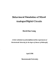
Fig. 3 Output from LVDT: a) Magnitudeof differentialAC output,b) Phaseangle
ofoutput relativeto primary,c) Magnitudeof DC outputfiom signalconditioner.
from null dependsupon the amplitudco1'theprimaryexcit;.ttion
nlaximumcore displacement
voltagcand thc scnsitivityfactorof the particularLVDT, but is typicallyscvcralvolts (rms).
to the primary excitationvoltage,stays
The phaseangleof the AC output (E,rcout),ref-erenced
constantuntil the centerof the corepassesthe null poilt, rvherethc phaseanglechangesabruptly
the
by 180",as shou'ngraphicallyin Figure3b. This 180' phaseshift canbc usedto determine
directionof the core positionliom the null by meansof appropriatecircuitry. This is shown in
the positionof thc core
Figure3c, where the polarity of the output signal(Ep6) represents
relativeto the null point. It is apparentfrom this figurc that the output lrom the LVDT is linear
over its specifiedcoremotion,and that the sensorcan bc usedover an extendcdrangewith some
reductionin outputlinearity.
'I'he
of using an LVDT as opposed
What arc the benefitsol usingan LVD'f?
advantages
can be listcdas fbllorvs:
to otherdisplacement
transducers
o
Friction-FreeOperutit.trt:
Thereis no mcchanicalcontactbetweenthe core and coil assembly
liG. Furthcmore,thc absence
of the LVDT, which meansit features
unlirnitedmcchanical
of friction permitsthc LVD-I' to respondvery last to changcsin core position. Only thc
of thc LVD'l'sensor.
inertialeffectsof the slightmassof the corelimit thc dynamicresponse
lnfinite Resolution:LVDT is an absoluteoutputdevice,as opposedto an incrementaloutput
inlinitesirnally
small changesin core positionbecauseit operateson
devrce. It measures
and outputdispiaylimit the
electromagnetic
couplingprinciples.Only the signalconditioner
intlnitcrcsolutioncapabilityof thc LVDI . Also due to this capability,the locationof the
intrinsicnull pointofthe LVDT is cxtremclystablcandrepeatable.
Single Aris Sensitivi4t:LVDT respondsto motion of the core along the coil axis, but it is
insensitiveto radial positionof the corc. Thcrelbrethe LVDT still functionswithout a
problemwhen thc core is misalignedand doesnot travel in a precrselystraightlinc.
SeparableCoil and Core: 1'hc coil asscmblycan be isolatedfion.rthe core by insefiinga
non-magnetictube betweenthe core and the bore. This tube can containa pressurizedfluid
ri,hen,fbr example,thc LVD] is uscdfbr spoolpositionfeedbackin hydraulicservovalves.
Over-travelDantage Resistant:The intemal bore o1'mostLVDTs is open at both ends. In
the eventof unanticipatcdover-travel,the core is able to passcompletelythroughthe sensor
coil assemblyrvithoutcausingdamagc.
to moistureand humidity,as wcll
LVDTs havesuperiorresistance
EnvironmentallyRr.;Drrsl:
'fhe
internalhighvibration
lcvels
in all axcs.
as to substantialshock loads and high
permcabilitymagneticshieldminirnizesthe efTcctsof extemalAC fields. The caseand core
are corrosionrcsistantand they can be hermeticallysealedusing a variety of rveldtng
processes.LVDTs can operateover a very rvide temperaturerange, tiom cryogenic
and radiationlevelsfound in many nuclearreactors.
temperatures
to elevatedtempcraturcs
)
What is the differencebetween(AC-AC) LVDT and (DC-DC) LVDT'I Both typesof
LVDTs u'ork basedupon the sameprinciplespresentedearlier. The (DC-DC) LVDT is an (ACAC) one with a built rn crrcuitry,rvhichsupportsthe (DC-DC) LVDT using (DC) input that
(DC) output. The maximum(DC) input voltagevariesfiom 6 to 30 V dependingupon
generates
thc type of LVDT (rnanufacturer).
Althoughan [.VDT is an electricaltransformcr,it
What is thc basicinstrurlentation?
requiresAC porverofan amplitudeand fiequencyquite dillerent fiom ordinary po\\'erllnes to
opcrateproperly(typically3 V rn.rsat 2.5 kHz-). Supplyingthis excitationpower lbr an LVDT is
ion, which is also knorvn as LVDT signal
one of sevcral functions of the instrumentat
conditioningcquipment.Otherfirnctionsincludeconvertingthe lou' level (AC) outputof the
LVDT into high level (DC) signalsthat are more convenientto use, decodingdircctional
inlbrmationfi'om 180' output phaseshift as the core o1'anLVDT movesthroughthe null point,
and providingan electricallyadjustableoutputzcro level. Figure 4 showstypical diagram
electronics.
representation
of LVDT signalconditioning
IN Stn u l,t Er.,,teT tot t
AC-ACLI/DT
availablefbr useat NSEL. A
Thereare a numberof pieccsof LVDT instrumentation
rvith LPC-2000of Macro Sensors(Reference1) is providcdin the
discussionof instrumentation
follorvingparagraphs.The user shouldalso be arvareof signal conditionerSCXI-15'10of
NationalInstruments(Refcrence3).
LPC-2000PorverSupplvand SignalConditioner
modules
Figure5a shor'vs
a setof six (6) LPC-2000powersupplyand signalconditioner
mountedin the enclosure(blue box) equippedadditionallyrvith a voltmeter,porversrvitch,
moduleselector,and outputrangeslvitch. Figurc 5b showsthe back of this systemrvith six
and six BNC outputconnectors.Figurc6 shorvsthe singlemodule,
LVDT bendixconnectors
rvhichsupportsgiven AC-AC LVDT. The LPC-2000is a compact,singlc channelAC-operated
o1-mostLVDTs. Operatingat ll0-220 V,
capablcof providingconditioning
signalconditioner
requiredto operatethe positionsensor
provides
all
necessary
circuitry
50-60 Hz, the LPC-2000
and providea high level, reducednoise analogDC output at the rangeof +10 V, which is
suitablelbr leeding analogor digital control indicators,ProgrammableLogic Controllersand
other systemindicatingand control instrumentation.The LPC-2000rnoduleis also capableof
I.
generatinga 4-20 mA loop output. Instructionrnanualfbr LPC-2000is availablein Rel'erence
Operationof the LPC-2000and AC-AC LVDT
I.
Connectthe LPC-2000porversupplyand signalconditioner(blue box) to thc I 10 V, 60 Hz
sourceof electricalpolver. Flip the toggle sr'vitch"POWER" on the po*'er supply (Figure
5a). Wait at least5 minutes(rvarm-uptimc) belbreproceedingto step2.
2.
Turn the "LVDT SELECT" to channelI (Figurc 5a). Srvitchthe "METER RANGE" to 2 V
in Figure7 intothe outletI (Figurc5b) Using
rangc(Figurc5a). Plugin thejumpershctrvn
ir
Automatic
amplitude
control
Fig. 4 LVDT supportelechonicsdiagram.
b)
Analog
output
LVDT
outlet
LPC 2000modulesin bluebox for usewith AC-AC LVDTs:
Fig. 5 Six Macrosensors'
a) Front view, b) Rearview.
7
I
.\
t-
I
I
I
I
I
Fig. 6 A moduleof Macrosensors'LPC 2000
for usewithAC-AC LVDT.
Fig. 7 Jumper.
I
I
Dial gauge
I
Housingof LVDT
I
I
I
Fis 8. Calibrator.
I
I
6
the "Zero"resistor(Figure6) anda smallscrewdriveradjustthe "METER" readingto 0.000
V. This meansthat the amplifier of the channel1 generates0.000V output. Repeatthis
operationfor all channelsto be used.
3 . Switchthe'METER RANGE"to 20 V range(Figure5a). Removethejumper from outlet I
(Figure5b) andplug in the LVDT connectorinstead.Mount the LVDT into the calibrator
(Figure8). Move the housingof LVDT up and down until the zero V (0.00 V) outputis
achieved.This meansthatthe electricalzero(null) of LVDT wasfound. Setthe dial gauge
of the calibratoralsoto zero. Move the housingof LVDT to its full range,e.g. 1 in. Using
(Figure6) until either-10.00V or +10.00V is
smallscrewdriver,
adjustthe"SPAN'resistor
achieved(thesigndependsuponthe directionof motionof the LVDT housing.Takeoutput
voltagereadingsevery10%of the LVDT readings;
e.g.for +1 in. LVDT, 0.1 in. interval
shouldbe used.Takethe readingsgoingin bothpositiveandnegativedirections.
,1
Plot the dataoutputvoltageversusdisplacement
andobtainthe leastsquareequationwhich
couldbe usedduringexperimental
datareduction.
5 . Repeatsteps3 and 4 for eachLVDT to be usedat eachchannel. The blue box supportsa
maximumof six channels.
6. Each blue box has a set of six analogoutputs(Figure 5b), which can be usedfor either
calibrationor datalogging.
DC.DCLVDT
SinceeachDC-DC LVDT has a built-in circuitry,which is an equivalentof LPC-2000,
any DC powersupplycanbe usedfor its operation.An exampleof DC power supplyis shown
in Figure9.
Operationof DC PowerSupplyandDC-DCLVDT
1. Connecta DC powersupplyto the 110V,60 Hz sourceof electricalpower. Turn it on
(Figure9) andwait at least30 minutes(warm-uptime)beforeproceedingto step2.
2. Adjust the outputDC voltage(excitationvoltage)from the power supplyto the value
usuallyit is between6 V and 30 V. Connectthe
specifiedby the LVDT manufacturer;
outputfrom DC powersupplyto the fansition box shownin Figure 10. Make surethat the
polarityis conect;minusgoesto minusandplusgoesto plus. If the polarityis reversed,
the
outputfrom LVDT will be closeto zero.
3. Connectthe LVDT to oneof six channelsof thetransitionbox (Figure10a). Also connecta
voltmeterto thetransitionbox (Figure10b). Mountthe LVDT into the calibrator(Figure8).
Move the housingof LVDT up anddownuntil the zeroV (0.00V) outputis achieved.Set
the dial gaugeof the calibratoralsoto zero. Apply the full rangeof displacementto the
LVDT. Adjust the excitationvoltagein sucha way that 10 V output from the LVDT is
achieved.Move the LVDT backto its zeropositionandapplythe full rangein the opposite
direction. The outputvoltageshouldbe equalor lessthan 10 V. If it is higherthan 10 V,
reducethe excitationvoltagein sucha way thatoutputof 10V is achieved.Move the
To ffansition box
Fig. 9 DC powersupply.
a)
b)
To power
supplyor
voltmeter
Analog
output
Fig. 10 Transitionbox: a) Frontview, b) Rearview.
l0
LVDT back to its zero position. Calibratethe LVDT by applying an interval of
displacement
equalto 10%of the fulI rangeof LVDT; e.g.for+1.0 in. LVDT, the intervalis
equalto 0.1in.
4. Plot the calibrationdata in the displacement-voltage
coordinates.Using the leastsquare
linearregressionmethod,determinethe equation6 : f(Uou, where 6 is the displacement
(in.) andUe'r is the outputvoltage(V) from the LVDT. An exampleof the calibrationline
is shownin Fieure11 wherer is thecorrelationcoefficient.
+ (0_70998)Uod,
6 r 0.0091283
r! 1.000
3n
,2.
5.4
3a.1
012
3
4
5
OutputVoltags,UodM
Fig. 11 An exampleof calibrationdatafor +/- 3.0 in. DC-DC LVDT.
INsrer-lertoN
whenmountingLVDTs?
Whatthingsshouldbe considered
Mountingfixtures,core extensionrods,and hardwarelocatedwithin an inch of the LVDT
shouldbe madeof nonferrousmaterialsthat arepoor electricalconductors.This is to avoid
by changingits magneticfield or by enablingeddy
compromisingLVDT performance
stainless
currentsthat work againstthis magneticfield. Prefenedmaterialsarenonmagnetic
plastics.Nonmagneticmaterialssuchasaluminum,brassandcopper
steelsandengineering
may alsobe usedprovidedthe massis smallandthe materialis split axially to impedeeddy
currentsconcentricto the LVDT.
Thebody ofthe L\IDT shouldbe securelyfastenedby clampingthe housingin a split block
or similarfixture. NSEL hassplit blocksmadeof a compositematerialcalledKevlor (Figure
12a). Thesenonmagnetic
blockscanbe machinedeasilyfor a particulartestapplicationand
for differentdiametersof LVDT housing.Figure12bshowsan LVDT insertedinto a Kevlor
block. Clampingthe body of the LVDT nearits electricalcenterwill minimize zero shift
with temnerafure.
ll
mnge
The core shouldbe positionedto allow ftee movementthroughthe entiremeasurement
of the LVDT. With proper alignment, the core will not contact the bore, resulting in
frictionlessoperation. If the contactis significant,frictional wear will result in non-linearity
anddegradationin sensitivity.
Fig. l2a Kevlor split block.
Fig. 12b LVDT insertedinto a Kevlor split block.
LVDTs beingusedto determinedisplacementsof a model frame,with the outer casingof
each LVDT attachedto an auxiliary supporting frame and the movable cores attachedin a
springJoadedfashionto the model, are shownin Figure l3a. The LVDT can alsobe adoptedto
act as a strain gaugeto monitor strainsover a moderateor extendedgagelength as shown in
Figure 13b. Otherapplicationsof LVDTs areshownin Reference2.
The range and number of LVDTs available at NSEL can be found at our website:
htto://cee.ce.uiuc.edu/nsel/Iacility/lvdt.htm.
t2
andstrains:a) LVDTs
Fig. 13 Useof LVDTs in measuringdisplacements
for
for deflectionmeasurements,
b) LVDTs
strainmeasurements.
RT,FERENCES
Ref. 1
InstructionManual. Line PorverOperatedLVDT Signal Conditioner,Model LPC2000(included).
Ref.2
Handbookof TransducerDesign,Engineerfurg
and Application,Trals-Tek lnc (partly
included).
Rel 3
SCXI-1540UserManual,8-ChannelLVDT SignalConditioner,NationalInstruments,
Mach 2000Edition.
Ref.4
Harris,H. G. and Sabnis,G. M. StructuralModelingand ExperimentalTechniques,
SecondEdition,1999.p. 348-352.
Ref.5
Herceg,E. E. Handbook of Measurementand Confol, publishedby Schaevitz
Engineering,1972.
I
13
-J
n"f. 6
Lion, K. S. Instrumentationin Scientific Research,published by McGraw-Hill Book
Company,Inc., 1959.
, I
{
Ref. 7
Ramsay,D. C. Principlesof EngineeringInstrumentation,publishedby HalstedPress,
1996.
I
Ref. 8
http://www.macrosensors.com
Ref. t
http://www.sentechlvdt.com
JI
t
-t
{
I
i
I
{
I
i
J
II
,i
I
I
I
I
I
I
I
.,
l
t
I
I
I
I
.l
I
Ref. 10 http://www.transtekinc.com
J
I
4
,l
,i
I
I
t.
i
II
I
I
i
I
i
I
I
,l
I
I
I
i
I
I
I
.
Reference1
ln,structionManual
Line Power
Operated
LVDT
$ignal Conditioner
ModelLPC-2OOO
U.S. Route t3O North
Pennsauken,NJ O81{|l.i541
Phone: 85G662-80OO
FAX: 85e3'l?-'l005
DESGN|PI|OX
capableofoperatingrnoslLVDTSandRVOTS.
TheLPC2000is a compactsinglechannelAoline powe.edsignalconditioner
Operating
from115V or 220VAC, 50.60Hz,an LPC2000providesall circuitryrequiredto operatean LVDTposilionsensor
andprovidea highlevel,lo\,vnoiseanalogDCoutputsuihblefor feedinganalogor digitalindicators,PLCS,andothersystem
indicatingandconuolinsfumentration
or a 4-20nA 3+Ji.ecunentloopoutputTheLPg2000featuresuser€eleclable
ate madevia
ftequencyandgainto functionwittlsensorshavingwidelydifferentsensitivitjes.Conneclions
excitiation
recessedscrewterminalsat thetoDandbottomof thecase whichmountson DINI or DIN3 rail.
SPEiCtF|GAI|OXS
...1| 5 or 220V AC,50-60l|z' 25 VA
PovrerInputVoltage.....
V ms (Nom.)
LVDTExcitation
Vo|tage...................................3
kHz,5 kHzor 10klts
LVDTExcitation
Frequency.................3
Ohms(min.)
LVDTPdmary
1mpedance........,.....................200
Output,
VoltageMode..................................t10V
DC@ 5 nA
Output,Curent
Mode.....,....,4-20
mAsourcing,
300ohmsmax
Frequency
Response..,
3 db at250Fts
<10mVnrs
Output
Ohms
Outputlmpedance,......
.........<10
FSO
Non1inearity..................
....10.01"/o
Temp.Range.,..,.....0"F
to +70'C)
Operating
!c +160"FG18'C
FSOfC)
Temp.Coeff.of Sens...-.......0.01yo
FSOrF(0.018%
.ZeroandSDan
Conbo1s..........,...,........
(200grams)
ounces
Weight........................,..........................7
MOUNTING
orDlN3,
TheLPC2000is designed
to mounton theDINrailmountingsysternincluding
DIN1,32mmX 15mmasymettical,
35mmX 7.5mmor 15mmsymmetical,r.lilsas illustratedbelow.
DIN I Mounting
l5mm
n
DIN 3 Mounting
2
LVDT
Secondaries
Yellow (E)
Primary
Red (A)
Mu.l b. cdn.cLd
tog.th.r, but
Hhl
-"""'
LJUttl
Blue(B)
t.?_t_ |
ll
Brown(F) Black(D)
r
-l------
rflo
Flt a
EO
@o
Top
Et{ ELo
rc,
Ltne
E
Llno
AC Lln€
Ground.
AC Power lnput
Wiring Note: The wire colorsand/orlettersshownin the connectiondiagramapplyonly to Macro
Sensors'standardAC LVDTSwith 6 leadwiresor 6-pinconnectors.For LVDTSwith otherterminationssuch as BB seriesgagingprobesor SQ seriesheavyduty LVDTS,or for extensioncablesused
with LVDTS,consultthe data sheetaccompanying
the LVOTor cablefor the correctcolorcodesor
terminalconnections.Connectthe LVDT'Sprimaryand secondariesto the signalconditioneraccording io the wiringdiagram,observingthe magneticpolaritydotson the LVDTwindingschematic.
3
GONNECTIONS
screwclampterminalsthatwillaccept
All wireconneclions
to the LPG2000a.ethroughindusfystandardrec€s.sed
wiresizesfrom#28AWG
to # 12AwG,eithersolidor stranded.
Wiresshouldbestipped5/16'(8mm)whichwill
providethe properlengthof conductor
withoutexposinganybarewire. Linepowerinputwiring shouldutilizea
minimum
sizeof #18AWG.Bestlretg de+neroizepowerlinepriorto makinopowerconnections.
INTERNAL ACGESS
It maybe necessary
to gainaccessto lhe insdeof tle LPG2000to adjustexcitationfrequencyand/orgainjumpers.
De.ene.oizelinepower.Usinga knifeblade,smallscrevvdriver
or similar
tool,genuypryoffthecoverat points
indicated
in figurebeb/v.
WARNING !
Danqerousvolhqes are presentinsideeneruizedunit I Be sure to decnemize unit prior
to rcmovalofcover!
-
It-
ffi
|.-
,flr,-*l
4
EXCITATION FREOUENGYSELEGTION
The LPC2000hasthreeuser€electable
LVDTexcitationftequencies.Thedesi.edlrequencyis normallysetb matchthe
specifications
and/orrecommended
operatjngfrequencyof lhe LVDTbeingused. As shippedfromthefaclory,theunitis set
for 3 kHz excjtationfrequencywhichis commonto manyLVDTS.Frequencyischangedbyjumpers(shortingba|s)on Sl, S2
and53. (seeFrgure1).As supplied,a jumperis positioned
adossSl as shownin Figure1. To obtain5 kHz,rnovethe
jumperfiomSl to S2. To obtain10kHz,movethejumperfromSl io 53. WARNINGI !q!!ags!!C lggeldzCgl4lC!
coveris removed.Oanoerous
voltaoesareoresentinsideeneroized
unitI
OUTPUT GAIN SELECTION
The LPC2000 can operatewith LVDTShaving a widerangeof sensitivities.Coa6egainselectionis providedto permit
operationwith most LVDTS. To set coarse gain,
oerformino
thefollowino
calculation:
Sensitivity
inVolts/.001"X Excitation
VoltageX FullStrokein thousandths
of an inch= FullScaleOutput(VAC rms)
Examplel: 4.050" Sfoke LVDT
Sensitivity:
X 3V rmsX 50 (12 rangein .001")= 0.975VACrmsFullSc€leLVDTOutput
0.0065V/.001"
Example2: tl.000" StrokeLVDT
Sensitiviv:
0.00065V/.001"
X 3V rmsX 1000(1/2rangein .001")= 1.95VACrmsFullScaleLVDTOutput
Gainnay be adjustedby placingjumpersS4,35, 56, andS7 (shortingbars)in positionsshownin thetablebelow.Placing
jumpersasinsbudedwillyielda t10 V OCoutputat fullscaleLVDTdisplacemenl
GAINSELECTION
TABLE
s4
s5
s5
s7
0 - 0.3v
Open
Open
Open
Open
u.31V- 0.bv
Open
Jumper
Open
Open
0.6'1V- 2.5V
Open
Jrmper
Open
Jumpel
Jumper
Open
Jumper
Open
.VDT Full Scale
)utput AC Volts
!tndicates.tumler
positions
asshipped
fromfac1ory
5
to
A requirement
mayexistwheremultipleLPG2000S
areto b€ usedandwhereunjlsorwiringwillbe locatedin closeproximity
theoscillators
of multipleunitsto preventcrossblk,beating,andinternodulation
eaci other.TheLPC-2000cansynchronize
betweenunib. To synchronize
the oscillators,
connecitogetherterminal5 on all unitsandconnectbgetherterminal10onallunits.
Theseconnections
are j!3gdi!9!..1ptheconnedionsshownon page3. Oneunitshouldbe designatedasthe"Mastefandthe
'Slaves'.
withthe insttuctions
balanceof the unitsdesignatedas
The'Mastef unifsexciiationfrequencymustbe sd in acco{dance
givenintheparagraph
"Excitation
Frequency
entitled
Seledion'.
Onthe'Masteiunit,movejumperlrom58 to 59. 'Slave"units
(shortng
ffom51,52, 53 and59.
musthaveajump€r(shorting
bar)on 58 andalljumpers
bars)mustberemoved
LPG-zO0 Slave l:l
Additional Connections For IPC-2000 Mult'rchannel
eMaster/Slave" Confi guration
GALIBRATION PROCEDURE(Voltage
Output)
jumperbetween
7 andI
Tocalibrate,
remove
LVDTsecondary
wire,usuallyRedo. (A)fromterminal
9. Inserttemporary
te.minals
(thisjumper
power
Adjusttheze.o
wjllberemoved
afierZeroadjustrnent).
ApplyAC
tgunitand
allowa 15 minute
wannup.
jumperfrom
controluntilan outputof 0 V DCis obtainedb€tveenterminals4 and5. De-energize
unitandremovetemporary
between
teminals7 and9. Re-connect
secondarywire
Redor (A)to terminal9,Applypowerto unitandmoveLVDTcoreor
pointfromwhich
thereference
bodyunlilanoutputof 0V DCis obtained.
Thisposition
isthetruenullofthesensorand
subseouent
oosition
measurements
aremade.
makethisadjustrnent
as closeas
NOTElf rnechanical
adjustment
of thecorcor LVDTbodyis difiicultor impossible,
possibleandthenadjusttheZerocontrolto obtain0 V OCoutput.lt is importantthatthe LVDTbewithin5oloof its kue nullposition
is withintheLVOTS
ratedlinearrange.Offsetsof morethan5%mayresultin non-linearresultsat
to ensurethatfull displacement
or neaafullscaledisglacem€nt.
Movethe LVDTcoreto its full scaledisplacement
andadjustthe Spancontrolto obiaina readingof 10V DC. Outputsof lessthan
bySpan
10V DCmaybeobtained
theSpancontol(e.9.5VDC).lfdesi.edfullscaleoutputcannotbeobtiained
byadjusljng
tableonpage
control
adjustment,
resetgainjumpers(shorting
bars)to nexthigheror lowersettingasshownin'GAINSELECTION"
to resetgainjumpers.Ecsg!el9-de=!!e!g!29-q!!
5 andthenreadjustSpanconkolto obtaindesiredoutput.lf it is necessary
Drioato removinocover.
Unitis nowreadyfor normaloperation.
GALIBRATION FOR 10O% ZERO OFFSET (Voltageoutput)
100%zerooflsetallowsthe userto obiaina unipolaroutputoverthefullrangeof theLVDT.
PROCEDURE"
section
fortullscaleuse,butadjusttheSpancontrolfor
inthe'CALIBRATION
Followtheinsfudionsasdescdbed
andadjusttheZerocontrol
halfthedesired
fullscaleoutput(e.g.5 V DC).MovetheLVDTcoreto'minLE'tullscaledisplacement
fordesired
tullscaleoutput.
andadjusttheSpancontrol
to obtainzerooutput.MovetheLVDTcoreto'plus"tullscaledisplacement
Repeat
thisprocedure
to ensurepropercalibration.
Unitis nowreadyfor unipolar
operation.
6
GALIBRAT]ON FOR 4-2OmA CURRENT LOOP OUTPUT
To calibEteunitfor cunentoutput,makesurethatcunentloopconnedions
aremadebetweenTenninals5 and6. Remove
jumperb€tweenterminals7 andI (thisjumperwill
LVDTsecondary
wire,usuallyRed(A)fromTerminal9. Insedtemporary
betemoved
afrerzercadjusiment).
ApplyACpowerlounitandallowa 15 minutewarrrup.Adjustzero
cgntroluntila
jumpertrom
readingof12mAis oblained.De-energze
unitandremove
between
Terminals
7 and9. Rg-connect
secondary
wireRed(A)to Terminal9. Applypowerto unit. Move LVDTcoreor bodyuntil12mAoutputis obtained.Thispositionis the
tue nullposition
of thesensorandthepointfromwhichsubsequent
measurements
aremade.
NOTE:lf mechanicaladjustrnent
of thecoreor LVDTbodyis difficultor impossible,
makethisadjustment
as close
possible
as
andthenadjusttheZerocontrolto obtain12 mAoutput. lt is importantthatthe LVDTbewithin5%of itstruenull
or zeropositionto insurethattulldisplacement
is withinthe LVDTSratedlinearrange.Offsetrs
of morethan5%mayresultin
non-linear
results
at or nearthefullscaledisolacement.
MovetheLVDTcoreto its"dJs' fullscaledisplacement
andadjustthe
Spancontroltoobtaina reading
of20 rnA Retum
the
coreto "minus"full sc€le positionandadjusttheZerocontrolto obtaina readingof 4 mA.l\4ovethe coreto the'plus"fullscale
positionandadjustthe Spancontrol!o obtaina 20 mAreading.Repeataboveprocedure
to ensureproperouFutat both
extremesof thecoretravel.
Unitis nowreadyfor normalcunentoutputopel-ation.
Directional Sense
Ifthe slopeof theanalogoutputvoltageor cu.rentis thereverseof the desi.edslopg,i.e.,if the ouFutvollageor cunentincreasesor deqeasesopposrteto the desireddirectionof coremotjon,revecethe LVDTconnections
to terminals7 andL
1.37
|
OUTLINE
Fom *io4.il R.v. Gltl @Hdad A S.na.vh2
lo€hnolotlG,
In.. 201,1. BacF S.nsoF ls t
rogl3t ..d tEd. o.ri of Howard A. Scha.vltz
-i
-i
I
I
J
I
I
I
.J
I
I
I
-J
I
I
)
i
I
I
)
I
It
I
.J
I
I
I
II
t
j
I
-)
I
I
I
2
Reference
l:'
- LVDT- LinearVariableDifferentialTransformer
i'
Tbchnology
Trans-Tekdesignsand manufacturesa broad line of linear
transducers
usingLVDT tecbrology. An LVDT, or
displacemenl
Linear Variable Differential Transformer,is an inductive device
containing primary and secondarycoaxial wound coils and a
fenomagneticcore. Excitingthe primarycoil with an AC voltage
generatesanelecfomagneticfield. The corelinks theelectromagnetic
coils,inducinga voltagein
freld ofthe primarycoil to thesecondary
each. The secondarycoils are q?ically wired in seriesopposition,
producingAC voltages180 degreesout of phasewith eachother.
The magnitudeof the voltagein eachsecondarydependson the
oositionofthe corerelativeto the coils.
NON-CONTACTING
CORE
II,,I
FINITE RESOLUTIOI.i
By design,the coredoesnot makecontactwith the imer diameter As an analogdevice,theoreticalresolutioncan be definedas
of the coils with proper aligffnent. This very important design infinite. Resolutionis the smallestincrementof movement
detail providesfrictionlessmovementof the corethroughthe detectable
betweenthe coreandcoils.
inner bore of the coils creatinginfinite mechanicallife.
Applicationsdemandinghigh reliability and low failure rates
benefitfiom this basicdesignfeatule.
NULL POSITION
When the physical center ofthe core is in line
with the electrical center of the coils. the
voltage induced in each secondaryis equal in
magnitude, but opposite in phase. When
summed, the secondaryvoltages cancel each
other, resulting in zero output volts. This is
the null position ofthe LVDT.
Primary Excitation
VRMS
,CEtl:
TE@W
This inherent symmetry in the LVDT
constructionallows for a highly repeatablenull
position. Many LVDT applications revolve
around this one feature, especially in closedlooD control svstems.
Pdmary Excitalion
VRMS
tG@,
EIE@:
}\{t*"
;+7^v^-.,-*,
:
Secondary 1
Secondary 2
p#,,,**
JaM.**,
Secondary1
C 0'R E ;il S1.ri: i"{: i\T
An LVDT is designedto have
symmetric measurement
rangeson eachsideofnull. As
the coremovesto onesideof
the null position, the
magnitudeof one secondary
b e c o m e sg r e a t e rt h a n t h e
other- Combining the two
secondaryvoltagesresultsin
anoutputvoltageproportional
to tbe core's distancefrom
null. Thephaseofthis voltage
indicates
whichsideofnullthe
is
localed.
core
Secondary
2
Pdmary Excitation
VRMS
,W@FEW
: EE@@Eg
:
frffi.,-".,$o-.,*o
Secondary 1
Secondary2
i
-r
t
,!
,a
i
:!
'7
iii:- D C i-r,,i3T^ i l\jT: G H,i L * IS r.:4,:_it I irrtjt'ii I ti I Ljfi
Signalconditioningis animportantconsiderationwhendesigning
anLVDT into an application.ConvertingtheAC outputvoltage
of the secondaries
into a usableDC outputvoltagerequiresa
andlow passfiltering.Designofthe circuitrymust
demodulator
take into accountfrequencyresponseand electricalnoise
considerations.For convenience
and easeof use,Trans-Tek
a completeline of DC-DCLVDTs, alsoknownas
manufactures
DCDTs,containingan integraloscillator/demodulator.
CUTPUTVS.DiSPLACEI./lENT
VDCOutsul
Discretecomponentsmakeup the integralsignalconditioner.
The oscillatorconvertstheDC voltageinputto ahigh frequency
AC voltage,poweringtheprimarycoil. A passivedemodulator
circuit reclifiesthe AC voltageoutputfrom the secondaries
and
differencesthe resultingsignalbeforefilteringwith a low pass
RC filter. The magnitudeandpolarity ofthe DC output voltage
are dependanton the positionof the core relativeto the null
position.
DC L\_/l: B!-CCK ]:.irc=ri\i
s
t;:
jl.:
{
Trans-Tek'sDC LVDTs are inputpolarityprotected,meaning
that polarity of the input leadsmust be observedfor proper
by polarityreversal.
operation,but theunit will not be damaged
TheDC voltageinputcanrangefrom 6 to 30 VDC, andmustbe
regulatedfor bestaccuracy.Themagnitudeofthe outputvoltage
is controlledby theinputvoltage.TheseDC LVDTs alsofeature
input andoutputcircuitsisolatedboth from eachotherandthe
which canbe usedin a
coil housing.The resultis a transducer
floating or groundretum system.
T
.i
i.v DT ir.,;ic
li \iTii\iG c ut jiSi_i!.iE5
Mountingfixtures,coreextensionrods,andhardwarewhich are
locatedwithin an inch of the transducershouldbe made of
nonferrous
materialsthatarealsopoorelectricalconductors.
This
is to avoid compromisingtransducerperformancedirectly by
changingtheshapeofthe unit's magneticfieldsor indirectlyby
enablingeddycurrentswhich work againstthe unit's magnetic
stainlesssteels
fields. Prefenedmaterialsincludenonmagnetic
and engineeringplastics. Nonmagneticmaterialssuch as
aluminum,brassand coppermay be usedprovidedthe massis
small and the material,is split axially to impedeeddy cunents
concentricto the LVDT. Iron and masneticsteelsshouldbe
avoided.
Thebodyofthe LVDT shouldbesecurelyfastenedby clamping
the housingin a split block or similarfixture. The useof set
screwsshould be avoided,as this may damagethe LVDT.
Clampingthebodynearthe electricalcenter,E., will minimize
zero shift with temperatue.The coreshouldbe positionedto
allow fiee movementthroughthe LVDT'S entiremeasurement
range.With properalignment,thecorewill not contactthebore,
resultingin frictionlessoperation.Contactbetweenthecoreand
the bore will not immediatelyaffecttransducerperformance,
however,significantfrictionalwearwill resultin a degradation
in sensitivitvandnonlinearifi.
:i
01F
LVDT
Applications
KnifeInlelligence
lor Garment
Machine
Automotive
PartsAssembly
Bottle
Height
Inspection
ooooo
Actuatorfeedbackis criticalin controllino
papercoatingthickness.
Heightis measuredby the positionof a verticalrod
comingin contactwiththe mouthof the bottle.
Automolive
Suspension
System
Durabilityof structuralcomponentsare
conlinuously
checkedunderconditions
of stress.
Measuresfluid levelthrough{loatpositioninsidea
valve, providingstablevehicleride performance.
Roller
Thickness
Measurement
Robolics
Joystick
Conlrol
1
.''
tn
achievedesiredmaterialthickness.
roboticarm followsoperatofsarm movement.
Weighing
Systems
Fluiddensityis determinedby measuringlhe
positionof a floatsuspended
in a knownflux liquid.
Hydraulic
Servovalves
(Using
Vented
LVDT)
Hvdraulic
---"'-..
Fiuid
LVDT
withVented
Housing
Knowingthe deflectionof a springandthe spring
constantleadsto the calculationof weiohtor force.
Hydraulic
Servovalves
(Using
lsolation
Tube)
Pressurized
lsolalion
Tube
lmmersedin compatiblehydraulicfluid,a venled
pressurethroughout
housingequalizes
the LVDT.
An isolationtube housesthe movingcoreand
proteclsthe LVDTfromthe highpressure
fluid.