1
IM150-2000 Instruction Manual_Layout 1 19/01/12 4:37 PM Page 1
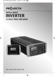
CONVERTS 12 VOLT DC – 230/240 VOLT AC
POWER INVERTER
POWERS HOUSEHOLD APPLIANCES
FROM A 12 VOLT BATTERY
P/No.s IM150, IM300, IM600, IM1000, IM2000
IM150-2000 Instruction Manual_Layout 1 19/01/12 4:37 PM Page 2
UÊ
UÊ
UÊ
UÊ
UÊ
UÊ
UÊ
UÊ
WARNING
For use with negatively earthed vehicles & systems only.
For indoor use out of weather only.
Internally bonded for safety, battery DC negative to case & AC socket earth .
Hazardous voltage inside - do not attempt to open or repair.
Do not use if damaged.
Read operating manual before using or making any connections.
Only connect 230/240V AC appliances that are in safe condition.
It is recommended that a type ‘A’ portable residual current device (RCD)
be used for added output protection.
U For independent use, do not connect to buildings.
FEATURES
UÊÊ*i>Ê*ÜiÀÊ/iV
}ÞÊÀÕÃÊ>««>ViÃÊÜÌ
Ê
}
ÊÃÌ>ÀÌÊÕ«Ê>`ð
UÊ
UÊ ÕÌÊÊÃ>viÌÞÊ«ÀÌiVÌÊ>}>ÃÌÊ
Ê«ÜiÀÊÛiÀ>`Ê>`ÊÜÊL>ÌÌiÀÞ°
UÊ i>ÛÞÊÕÌÞÊ«ÜiÀÊi>`ÊÜÌ
Ê>VViÃÃÀÞÊ«Õ}Ê£xäÊÞ®°
UÊ i>ÛÞÊÕÌÞÊ«ÜiÀÊi>`ÃÊvÀÊ`ÀiVÌÊL>ÌÌiÀÞÊViVÌÊiÝVi«ÌÊ£xä®°
UÊ ««ÀÛi`Ê-É <-Ê«ÜiÀÊÕÌiÌÊÃViÌðÊ
UÊ /ÜÊ«ÜiÀÊÕÌiÌÊÃViÌÃÊiÝVi«ÌÊ£xäÊEÊÎää®°
UÊ /ÕÀLÊV}Êv>ÊÎääÊÞ®°
UÊ /i«iÀ>ÌÕÀiÊVÌÀi`Ê>ÕÌ>ÌVÊV}Êv>ÊiÝVi«ÌÊ£xäÊEÊÎää®°Ê
2
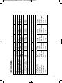
Standard Auto Blade Fuse
1x20A
External
Cig Plug 800m
16.5 x 12.5 x 5.2
0.6kg
Replacement Fuse
Fuse Quantity & Size
Fuse Location
Connection Cable
Dimensions (cm)
Weight
6mm2/900mm
0.8kg
1.5kg
19 x 21 x 7
External
3x25A
External
18 x 12.5 x 5.2
2000W
1000W
800mA
120A
IM1000
2.9kg
30 x 24 x 8
16mm2/1100mm
Internal*
6x20A
Automatic temperature controlled
3mm2/900mm
1x40A
65˚ (±5˚ C)
Manual
N/A
Cooling Fan
Alarm 10.5 Volt/Shutdown 10.0 Volt (+/-0.2 Volt)
Low Battery Alarm/Shutdown
Thermal Shutdown
85–90%
Efficiency
600W
300W
1200W
300W
600W
Continuous Output Power (Watt) 150W
Peak Output Power (Watts)
680mA
230/240 Volt AC, 50Hz (Modified Sine Wave)
75A
Output
570mA
12A
260mA
Input Current: (Max DC Amps)
30A
IM600
Input Standby Current (+/-5%)
12V Battery/Vehicle (10–15 Volt DC)
Input
IM300
IM150
P/No.
SPECIFICATIONS:
5.2kg
47x 24 x 8
25mm2/1100mm
Internal*
12x20A
4000W
2000W
800mA
240A
IM2000
IM150-2000 Instruction Manual_Layout 1 19/01/12 4:37 PM Page 3
3
IM150-2000 Instruction Manual_Layout 1 19/01/12 4:37 PM Page 4
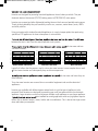
WHAT IS AN INVERTER?
Inverters are designed for powering household appliances from a battery or vehicle. They are
electronic devices that convert (12V DC) battery power to (230/240V AC) mains power.
Inverters are compact and often lightweight making them an ideal source of portable mains power.
Thanks to their portability they are commonly used in cars, caravans, motor homes, boats, 4WD’s
and utility vehicles.
Using an inverter with standard household appliances is a much cheaper option than purchasing
specialised 12V appliances for times when power is not available.
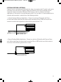
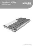
between the two is how close the output replicates mains power.
ed sine wave and true
sine wave inverters.
400
400
400
300
300
300
200
200
200
100
100
100
0
0
0
-100
-100
-100
-200
-200
-200
-300
-300
-300
-400
-400
MAINS POWER (SINE WAVE)
-400
MODIFIED SINE WAVE
TRUE SINE WAVE
Logically it follows that the process used in a true sine wave inverter is more complex than a modied sine wave inverter and subsequently they are lot more expensive.
ed sine wave and hence they are
more common.
True sine wave inverters are reserved for use on medical equipment and sensitive electrical
appliances.
Inverters are available with different power output levels to suit the type of appliances to be
powered. Small inverters are designed for powering one small low power electrical or electronic
appliance. Larger inverters can be used to power multiple small appliances or one larger appliance.
cient method for running appliances with very high power requirements such as electric heaters, stoves, kettles and air conditioners. This is due to their high current
draw and battery consumption.
4
IM150-2000 Instruction Manual_Layout 1 19/01/12 4:37 PM Page 5
CONNECTIONS / CONTROLS & ACCESSORIES
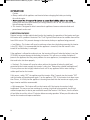
After unpacking your inverter take a moment to check that you have all the correct accessories for
your model and familiarise yourself with the connections and controls.
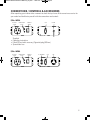
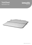
P/No. IM150
AC OUTPUT
SOCKET
POWER & FAULT
LIGHTS
POWER ON
SWITCH
FUSE
CHASSIS GND
FRONT
DC CORD
REAR
Supplied:
U Operating instructions
U Fitted DC cord with accessory (Cigarette) plug (800mm)
U Spare blade fuse
P/No. IM300
AC OUTPUT
SOCKET
POWER & FAULT
LIGHTS
FRONT
POWER ON
SWITCH
DC TERMINALS
CHASSIS GND
FUSE
FAN
REAR
5
IM150-2000 Instruction Manual_Layout 1 19/01/12 4:37 PM Page 6
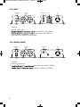
P/No. IM600
POWER & FAULT
LIGHTS
POWER ON
SWITCH
AC OUTPUT
SOCKETS
FRONT
DC TERMINALS
CHASSIS GND
FUSES
FAN
REAR
Supplied:
U Operating instructions
U
tted with battery clips (900mm)
U
tted with battery clips (900mm)
U Spare blade fuse (IM300) or fuses (IM600)
P/No. IM1000 & IM2000
POWER & FAULT
LIGHTS
POWER ON
SWITCH
AC OUTPUT
SOCKETS
FRONT
Supplied:
U Operating instructions
U
U
6
DC TERMINALS
CHASSIS GND
FAN
REAR
tted with ring terminal (1100mm)
tted with ring terminal (1100mm)
IM150-2000 Instruction Manual_Layout 1 19/01/12 4:37 PM Page 7
PLACEMENT / LOCATION / MOUNTING OF INVERTER
Caution:
UÊ
UÊ Batteries should be mounted in a separate well-vented enclosure.
UÊ For vehicle or camping use the inverter must be protected from rain, water or moisture.
Projecta inverters are designed for indoor, out of weather use only. For best performance the
inverter must be used or mounted in a cool, dry, clean and well-ventilated area.
For best TV / Radio reception keep inverter as far away from TV’s, radios, antenna cables and
antennas as possible.
Some models are supplied with mounting brackets (except IM150 & IM300). If used in mobile
applications such as 4WD, Caravan, Motor home or boat the inverter should be mounted to
a suitable horizontal or vertical panel, with at least 20cm clearance from the rear panel of the
inverter to provide good ventilation for the cooling fan.
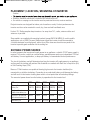
SUITABLE POWER SOURCE:
In order to operate the inverter and supply power to an appliance a suitable 12V DC power supply is
required. This can be a vehicle or caravan battery, portable power pack or an independent 12V lead
acid battery. For most applications, a deep cycle battery is recommended for best performance.
The size of the battery used will determine how long the inverter will supply power to an appliance
and how well the inverter will perform. Most batteries are marked with their size in Amp hours (Ah)
or Cold Cranking Amps (CCA).
Because 12 Volt inverters are capable of drawing high currents the inverter should only be
connected to a suitable size battery. Connection to an undersized battery could damage the battery
and will result in the inverter shutting down within a short period due to low battery voltage.
The amount of power drawn from the battery is proportional to the inverter load.
P/No.
IM150
IM300
IM600
IM1000
IM2000
Minimum Recommended
Battery Size
17Ah
(100CCA)
24Ah
(200CCA)
50Ah
(400CCA)
75Ah
(550CCA)
85Ah
(600CCA)
Run time with maximum
load & minium battery size
40min
40min
30min
15min
5min
Run time for a 100 Watt globe
with minimum battery size
80 min
2 hours
4 hours
6 hours
7 hours
Ideal battery size
50-70Ah
50-70Ah
50-130Ah 75-250Ah
85-400Ah
7
IM150-2000 Instruction Manual_Layout 1 19/01/12 4:37 PM Page 8
CONNECTION TO POWER SOURCE & EARTHING
U
U
U
U
Caution:
Even though the inverter is powered from a battery, it still produces Dangerous High Voltage
AC power and has the potential to fatally injure if incorrectly installed or used.
Before making any connections ensure inverter is switched off and has no AC appliances
plugged into the AC output sockets.
Ensure vehicle / system is a negative earthed or negative ground system only.
Double check battery negative and positive posts before making any connection, a wrong
connection (Reverse polarity) will cause the fuse/s to blow and may damage the inverter.
U
when the inverter has not been used for some time. This spark is caused by the inverter’s large
capacitors charging quickly. To minimise this, make the last connection quickly and completely.
U
U Batteries can be dangerous, follow all battery manufacturer’s instructions and warnings.
U Projecta inverters are designed FOR INDEPENDENT USE ONLY. That is, they cannot be
connected to household wiring whether the building is connected to the electricity grid or not.
U Never operate the inverter without the DC negative input connected direct to the battery and
never install a fuse, circuit breaker or battery switch in the negative supply line
(IM150 excepted).
P/No. IM150
Making the DC connection on the IM150 is easy with the supplied lead and accessory
(cigarette) plug:
U Insert the accessory plug into your vehicle’s 12 Volt accessory (cigarette) socket.
You may need to turn the ignition key to the “Accessory” position to energise the socket and
provide power to the inverter.
U The IM150 does not need any external earthing, however an external earth connection
(Chassis GND) has been provided on the rear panel, this connection can be used to help reduce
radio / TV interference, see the section on external earthing.
P/No. IM300, IM600, IM1000 & IM2000
These inverters can be connected to a power source on a temporary basis with the supplied
DC leads (see the section Temporary Connection) or hard wired for a permanent installation
with suitably sized cable and hardware for your application (see the section Hard Wired
Connection). Regardless of which connection method is used it may be advantageous to earth
the inverter case, see the section on External Earthing for more details.
8
IM150-2000 Instruction Manual_Layout 1 19/01/12 4:37 PM Page 9
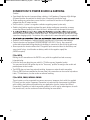
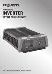
TEMPORARY CONNECTION:
U Connect the ring terminal on the negative lead (Black) to the negative (Black) DC terminal on
the back of the inverter.
U Connect the battery clip (Black) or ring terminal (IM1000, IM2000) on the other end of the lead
to the negative DC supply or (-) battery terminal.
U Connect the ring terminal on the positive lead (Red) to the positive (Red) DC terminal on the
back of the inverter.
U Connect the battery clip (Red) or ring terminal (IM1000, IM2000) on the other end of the lead
to the positive DC supply or (+) battery terminal.
INPUT
POS.
CHASSIS
GND
+
INPUT
NEG.
–
9
IM150-2000 Instruction Manual_Layout 1 19/01/12 4:37 PM Page 10
“HARD WIRED” CONNECTION
When mounting the inverter in a vehicle, caravan, boat or cabin it may be preferable to use
longer DC battery cables than those supplied, so that the inverter can be placed in a more
convenient, cooler or more protected location.
If longer cables are required only use suitably insulated automotive battery cable according to the
following table (Note: B&S = AWG)
P/No.
IM300
IM600
IM1000
IM2000
Up to 2m 8 B&S
(8mm2)
6 B&S
(14mm2)
3 B&S
(26mm2)
2 B&S
(32mm2)
3m
8 B&S
(8mm2)
3 B&S
(26mm2)
2 B&S
(32mm2)
0 B&S
(49mm2)
4m
6 B&S
(14mm2)
2 B&S
(32mm2)
0 B&S
(49mm2)
00 B&S
(64mm2)
6m
3 B&S
(26mm2)
0 B&S
(49mm2)
00 B&S
(64mm2)
Not
Recommended
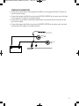
UÊÌÊÃÊÀiVi`i`ÊÌ
>ÌÊ>ÊVÀVÕÌÊLÀi>iÀÊÀÊ
}
ÊVÕÀÀiÌÊvÕÃiÊLiÊ«>Vi`ÊÊÌ
iÊ
Ê«ÃÌÛiʳ®ÊiÊ
close to the battery.
P/No.
IM300
Fuse or Circuit
40AMP
Ài>iÀÃÊÃâiʳ®Ê"Þ
IM600
IM1000
IM2000
100AMP 150AMP 250AMP
(or 2 x 150AMP
in parallel)
UÊÌÊÃÊÀiVi`i`ÊÌ
>ÌÊ>Ê
i>ÛÞÊ`ÕÌÞÊL>ÌÌiÀÞÊÃÜÌV
ÊÜÌ
Ê>ÊVÕÀÀiÌÊÀ>Ì}Ê
}
iÀÊÌ
>ÊÌ
iÊvÕÃiÊ
ÌÌi`ÊÊÌ
iÊ
Ê«ÃÌÛiʳ®ÊiÊVÃiÊÌÊÌ
iÊL>ÌÌiÀÞÊÌÊ>ÜÊÌ
iÊÃÕ««ÞÊÌÊÌ
iÊ
ÛiÀÌiÀÊÌÊLiÊÃÜÌV
i`Êvv]ÊÌ
ÃÊV>Ê>ÃÊLiÊ>V
iÛi`ÊLÞÊÕÃ}Ê>ÊVÀVÕÌÊLÀi>iÀÊÜ
V
Ê
>ÃÊ
a trip facility.
UÊ*ÃÌÛiÊ>`Ê i}>ÌÛiÊV>LiÃÊÃ
Õ`ÊLiÊÀÕÊVÃiÊÌ}iÌ
iÀÊÌÊÀi`ÕViÊV>LiÊ`ÕVÌ>Vi]Ê>`ÊLiÊ
protected from damage by corrugated conduit.
FUSE
SWITCH
CORRUGATED CONDUIT
10
IM150-2000 Instruction Manual_Layout 1 19/01/12 4:37 PM Page 11
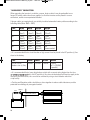
EXTERNAL EARTHING: (OPTIONAL)
Projecta inverters have been internally bonded for safety, by connecting the AC socket/s earth pin to
the inverter case and to the DC negative supply input. Because of this most installations do not
require the inverter to be earthed. However if the inverter is used in a stationary land based
application or if the inverter is causing interference with TV sets or radios it is recommended that an
external earth connection is made by one of the following methods:.
U External Earthing Stationary Applications --Connect an earth wire (Preferably solid Green
or Green with Yellow stripe) from the external earth connection (Chassis GND) on the rear of the
inverter to a metal stake or pipe that is driven into the ground at least 1.2m.
EARTH STAKE 1.2M
U External Earthing Mobile Applications --Connect an earth wire (Preferably solid Green or Green
with Yellow stripe) from the external earth connection (Chassis GND) on the rear of the inverter to
the chassis of the vehicle or ground wires in a boat.
Ê
CHASSIS CONNECTION
11
IM150-2000 Instruction Manual_Layout 1 19/01/12 4:37 PM Page 12
OPERATION
Caution:
U Always switch off the appliance and inverter before recharging the battery or starting
the vehicle engine.
U
connected to the mains grid. Normally AC wiring contains a M.E.N. link, this neutral to earth
link will damage the inverter.
U This inverter is designed for direct connection to appliances however extension leads and
power boards can be used.
PROTECTION FEATURES
Projecta inverters include sophisticated circuitry that monitors the operation of the inverter and turns
the inverter off if a problem is detected. The “Fault” light will illuminate and an audible alarm will be
heard if this occurs. This prevents damage to the inverter, battery or appliance being powered.
U Low Battery - This feature will sound a continuous alarm when the battery powering the inverter
is low (10.5 Volts). It is recommended that the appliance is turned off, then the inverter is also
turned off and the battery is recharged.
If the appliance is allowed to continue to run, the inverter will turn off when the battery is very low
(10.0 Volts) to prevent damage to the battery or inverter. This will cause a sudden disruption of
power to the appliance that may cause problems for some appliances, for example most computers
that need to be shut down properly.
U Overload - This feature will sound an alarm and turn the inverter off when the total load
connected to the inverter exceeds the inverter’s rating (see “Determining suitable load/appliance”)
This may also occur due to highly inductive loads such as any appliance with a motor causing a
sudden peak load on the inverter.
If this occurs, switch “OFF” the appliance and the inverter. After 2 seconds turn the inverter “ON”
and the inverter will provide power again. Turn the appliance “ON”, if the inverter shuts down more
than 3 times, it is likely that the appliance is drawing more load than the inverter can supply, and a
larger inverter would be recommended.
UÊ}
ÊÌi«iÀ>ÌÕÀiÊ/
ÃÊvi>ÌÕÀiÊÜÊÌÕÀÊÌ
iÊÛiÀÌiÀÊvvÊvÊÌ
iÊÛiÀÌiÀÊ
>ÃÊÀi>V
i`Ê>Ê
}
Ê
temperature. This may occur from continuously running a high load for long periods, due to high
ambient temperatures or due to poor ventilation around the inverter. If this occurs, turn the inverter
off and allow to cool for at least 15 minutes before resuming operation. Where possible reduce the
load on the inverter and improve ventilation.
12
IM150-2000 Instruction Manual_Layout 1 19/01/12 4:37 PM Page 13
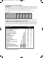
DETERMINING SUITABLE LOAD / APPLIANCES:
tted with 1 or 2 approved AS/NZS Australian socket outlets (depending on model)
either or both sockets can be used, as long as the combined load (Watts required to run appliance)
does not exceed the inverters’ continuous rating. All appliances have a rating plate that shows the
amount of power (Watts) used or the current (Amps) drawn under normal use.
The following table shows the maximum combined AC Watts or AC Amps which can be run
by the inverter.
P/No.
IM150
IM300
IM600
IM1000
IM2000
AC Combined max load (Watts) 150W
300W
600W
1000W
2000W
AC Combined max load (Amps)
0.6 A
1.2 A
2.4 A
4.0 A
8.0 A
Number of sockets
1
1
2
2
2
Some appliances that use an electric motor or transformer may draw 2 to 6 times their rating when
cult for the inverter to run.
For these appliances it is often a matter of trial and error to see what size inverter they will run on,
if in doubt always use a larger inverter. The following table is a guide to the appropriate AC Watt
drawn by various appliances. The DC Amps column shows the approximate power drawn from the
12 Volt supply.
Approximate
AC Watts DC Amps
Circular Power Saw/Electric Chainsaw
Toaster/Sandwich Maker
Small Household Vacuum Cleaner
Belt Sander & other Power Tools
Small Microwave Oven (500/600W)*
Combo TV/VCR
Power Drill/Portable Grinder
Flood Lights (500W)
Submersible Pump*
Small Colour Television*
Small Power Tools/Flourescent Light*
Juicer/Blender
Bar Fridge*/Large Stereo/PA Amplifier
Hand Mixer
Laptop Computer/Electric Knife
Portable Stereo/CD/DVD/VCR/Playstation
Charger/Mobile Phone/Camera/Camcorder
Shaver
2000
1500
1250
1000
900
750
600
500
400
350
300
250
200
175
150
100
50
25
IM150
IM300
IM600
IM1000
IM2000
APPLICATION CHART
Appliance
175
140
95
92
83
69
50
46
37
32
28
23
19
16
12
9
5
2
*Appliance may require a larger inverter.
13
IM150-2000 Instruction Manual_Layout 1 19/01/12 4:37 PM Page 14
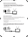
CONNECTING APPLIANCE AND RUNNING INVERTER
UÊÊ
iVÌÊÌ
iÊ>««>ViÊ
Ê«Õ}ÊÌÊÌ
iÊÛiÀÌiÀÊ
ÊÕÌiÌÊÃViÌ°
UÊÊ-ÜÌV
ÊÌ
iÊÛiÀÌiÀʺ" »]ÊÌ
iʺÀii»Ê«ÜiÀÊ}
ÌÊÜÊÕ>ÌiÊÌÊ`V>ÌiÊ«iÀ>Ì°
UÊÊ
Ê ÛiÀÌiÀÊÊLivÀiÊÃÜÌV
}ÊÌ
iÊ>««>ViÊÊ>`Ê>Ü>ÞÃÊÌÕÀÊÌ
iÊ>««>ViÊvvÊLivÀiÊ
Ê ÃÜÌV
}ÊÌ
iÊÛiÀÌiÀÊvv°
UÊ 7
iÊÌÊÊÕÃiÊÌÕÀÊÌ
iÊÛiÀÌiÀÊvv°
Ê Ê
(1) SWITCH ON
(2) SWITCH ON
RESIDUAL CURRENT DEVICE (RCD)
ÀÊ>``i`ÊÃ>viÌÞÊÌÊÃÊÀiVi`i`ÊÌ
>ÌÊ>Ê/Þ«iʺ»Ê,iÃ`Õ>Ê
ÕÀÀiÌÊiÛViÊ,
®ÊLiÊÕÃi`ÊvÀÊ>ÞÊ
>««>ViÊÌ
>ÌÊÃÊLi}Ê«iÀ>Ìi`ÊLÞÊÌ
iÊÛiÀÌiÀ°Ê/
iÃiÊ>ÀiÊÃiÌiÃÊV>i`ʺ->viÌÞÊ-ÜÌV
iûÊ>`Ê
>ÀiÊ`iÃ}i`ÊÌÊLiÊViVÌi`ÊLiÌÜiiÊ>`Ê>««>ViÊ>`Ê«ÜiÀÊÃÕÀVi°
£°Ê iVÌÊÌ
iÊ,
ÊÌÊÌ
iÊÛiÀÌiÀÊ
ÊÕÌiÌÊÃViÌ
Ó°Ê iVÌÊÌ
iÊ>««>ViÊÌÊÌ
iÊÌ
iÀÊi`ÊvÊÌ
iÊ,
Î°Ê /ÕÀÊÌ
iÊÛiÀÌiÀʺ" »
{°Ê ÜÊÌ
iÊ>Õv>VÌÕÀiÀ½ÃÊÃÌÀÕVÌÃÊÌÊÌÕÀÊÌ
iÊ,
ʺ" »Ê>`ʺ/-/»ÊÌ
>ÌÊÌÊÃÊ
Ê vÕVÌ}ÊVÀÀiVÌÞ°
x°Ê /ÕÀÊÌ
iÊ>««>ViÊ°
>Õv>VÌÕÀiÀÊ>`Ê>Ü>ÞÃÊvÜÊÌ
iÊ>Õv>VÌÕÀiÀ½Ãʺ/-/»Ê«ÀVi`ÕÀiÊÌÊV
iVÊÌ
>ÌÊÌ
iÊ,
ÊÃÊ
vÕVÌ}ÊVÀÀiVÌÞ°
(1) SWITCH ON
(2) RCD
SWITCH ON
(3) SWITCH ON
14
Ê
IM150-2000 Instruction Manual_Layout 1 19/01/12 4:37 PM Page 15
TROUBLESHOOTING / FAQ:
Q. Why does the inverter turn itself off?
A. If the inverter makes a beep sound and the “RED” fault light illuminates this indicates that there
is a problem, and the inverter will usually turn off. Most commonly this would be caused by an
appliance that is drawing too much power (overloading), low battery voltage or voltage drop due
cient size cables or poor connections (see section on protection features, page 12).
Q. The inverter will not run my appliance even though the appliance draws less power
(Watts) than the size of the inverter?
A. Electrical appliances can be divided into three groups by the way they draw energy (current) from
their power supply. These groups are “Resistive”, “Inductive” and “Capacitive” appliances or also
called “loads”. Some appliances may draw all three types of power.
(watts) from the power supply, that is a 100 Watt light will draw approximately 100 Watts from
the power supply at all times. Resistive loads are the easiest appliances for an inverter to run.
UÊ`ÕVÌÛiÊ>`ÃÊÃÕV
Ê>ÃÊ>ÊÀivÀ}iÀ>ÌÀÊiVÌÀVÊÌÀ®ÊÀiµÕÀiÊ>Ê>À}iÊÀÕÃ
ÊvÊ«ÜiÀÊÃÕÀ}iÊVÕÀÀiÌ®
to start and then usually draw a more constant power once running. Inductive loads contain coils
rst turned on these coils of
- The most common inductive appliances are: fridges, air compressors, transformers/chargers,
uorescent lights. These appliances can draw 2 - 6 times their normal
running power to start up, that is to run a 190 Watt fridge you may need a 600 or 1000
Watt inverter.
UÊ >«>VÌÛiÊ>`ÃÊÃÕV
Ê>ÃÊ>ÞÊ/6½ÃÊÀÊ>ÞÊiiVÌÀVÊ>««>ViÃÊÀiµÕÀiÊ>Ê>À}iÊÃÕÀ}iÊVÕÀÀiÌ
to start only when they have not been used for a while. This is often due to large capacitors in
Ì
iÊ«ÜiÀÊÃÕ««ÞÊÌ
>ÌÊÕÃÌÊLiʵÕVÞÊV
>À}i`ÊÜ
iÊÌ
iÊ>««>ViÊÃÊÌÕÀi`Ê°ÊvÊÌ
iÊ>««>Vi
may allow these appliances to work.
UÊ There are some appliances such as large refrigerators, air conditioners and other pump driven
appliances that have extremely high start up currents, because they have an inductive motor that
must start under load. These appliances are not recommended for use with an inverter. They
should be powered by an engine driven generator.
Q. The inverter is powering my portable television, but I cannot get a clear picture?
°ÊÊ«ÀÊÀiVi«ÌÊ>Ài>ÃÊÌÊÃʵÕÌiÊVÊÌÊ
>ÛiÊÃiÊÌiÀviÀiViÊÊ>Ê«ÀÌ>LiÊ/6ÊÃÕV
Ê>Ã
UÊ /Ê«ÀÛiÊÞÕÀÊ«VÌÕÀiʵÕ>ÌÞ\
Êii«ÊÌ
iÊÛiÀÌiÀÊ>ÃÊv>ÀÊ>Ü>ÞÊvÀÊÌ
iÊ/6Ê>ÃÊ«ÃÃLi°
Ê1ÃiÊ>ÊiÝÌiÀ>Ê}ÊÀ>}iÊÀÊvÀ}iÊ>Ài>Ê/6Ê>Ìi>ÊÜÌ
Ê}`ʵÕ>ÌÞÊV>Ý>ÊV>Li°
- Earth (Chassis GND) the inverter (see section on earthing, page 11)
15
IM150-2000 Instruction Manual_Layout 1 19/01/12 4:37 PM Page 16
Q. Can I run fluorescent lighting from my inverter?
A.
ne on an inverter even though they may
be slow to start.
UÊ Fluorescent lights are an inductive & capacitive load and often draw at least twice as much
power from the inverter than their normal rating to start.
uorescent lights should be avoided, because they contain power factor
correction capacitors. Power factor correction is used in normal buildings to help smooth out the
uorescent light ballasts. If used with portable power inverters the power
ed waveform, this causes a
uorescent lights must
capacitor. The light should then be marked “For Inverter Use only”.
Q. Why does it damage the inverter if the battery leads are connected back to front?
A. Your inverter uses sophisticated electronics to convert DC battery power to AC mains power.
If you accidentally connect the inverter to the battery incorrectly (reverse polarity) a large current
will be drawn by the inverter which will blow the protection fuses, as this occurs some of the high
current could damage sensitive electronic components. Because of this risk it is important to
always double-check the battery polarity before making any connections.
Q. How do I check or change the fuses?
A.
unit does not function, disconnect the inverter from the DC power source and disconnect any AC
appliances. Remove the black fuse caps, then remove the fuses and check if they are blown.
Replace blown fuses with the spares provided or standard automotive blade fuse of the correct
rating. The IM1000 & IM2000 contain internal fuses, these should only be checked or replaced
by a qualified electrical appliance repairer.
THE DC SUPPLY MUST BE DISCONNECTED BEFORE ANY REPAIR, THEN TURN THE ON/OFF
SWITCH OF THE INVERTER “ON” TO DISCHARGE THE CAPACITORS.
Q. Why do lights operating from the inverter start dim and then get brighter.
A. Projecta inverters feature “Peak Power Technology”. This feature allows the inverter to ramp up
its voltage output. This gradual increase in power allows appliances to operate with a “SoftStart” ensuring superior operation and helps the inverter to power inductive loads.
Q. Why does the fan only operate sometimes on IM600, IM1000 & IM2000 inverters?
A. These inverters feature a temperature controlled automatic cooling fan that only operates when
needed. This allows the inverter to run very quite for most of the time.
16
IM150-2000 Instruction Manual_Layout 1 19/01/12 4:37 PM Page 17
Q. Why does my Residual Current Device (RCD) trip each time I turn an appliance on?
A. Some RCD’s disconnect (trip) when they do not receive any power. These types of RCD’s can be
tripped by the inverter’s Peak Power Technology which allows a gradual ramp up of power. Use a
continuous RCD which does not trip out when the power is turned off, these only trip when there
is a fault.
Q. Why do some power tools not work properly?
A. Some newer power tools use PWM variable speed controllers to vary the tool’s speed as the
trigger is squeezed. These power tools switch the power on and off very quickly in a similar way
to how the inverter works. Because of this, some may not function properly with the inverter’s
modified sine wave output.
Q. Can I run laptop computers?
A. Most laptop/notebook computer AC power adapters work perfectly fine with the inverter’s
modified sine wave. Some however are more sensitive and may not function properly. If your
power adaptor does not function or causes a humming noise it is probably not compatible.
The best way to operate a laptop/notebook from your vehicle is to use the Projecta 12 Volt
Laptop Power Adaptor P/No. DC3500. This is a much more convenient and efficient way
to charge and operate the laptop direct from a 12V source.
Q. Can I connect lights with dimmers to the inverter?
A. Older light dimmers may function fine but most newer light dimming circuits are designed for
household sine wave AC power, these may not work properly with modified sine wave inverters.
17
IM150-2000 Instruction Manual_Layout 1 19/01/12 4:37 PM Page 18
Q. Can I run fluorescent lighting from my inverter?
NOTES:
A.
ne on an inverter even though they may
be slow to start.
UÊ Fluorescent lights are an inductive & capacitive load and often draw at least twice as much
power from the inverter than their normal rating to start.
uorescent lights should be avoided, because they contain power factor
correction capacitors. Power factor correction is used in normal buildings to help smooth out the
uorescent light ballasts. If used with portable power inverters the power
ed waveform, this causes a
uorescent lights must
capacitor. The light should then be marked “For Inverter Use only”.
Q. Why does it damage the inverter if the battery leads are connected back to front?
A. Your inverter uses sophisticated electronics to convert DC battery power to AC mains power.
If you accidentally connect the inverter to the battery incorrectly (reverse polarity) a large current
will be drawn by the inverter which will blow the protection fuses, as this occurs some of the high
current could damage sensitive electronic components. Because of this risk it is important to
always double-check the battery polarity before making any connections.
Q. How do I check or change the fuses?
A.
unit does not function, disconnect the inverter from the DC power source and disconnect any AC
appliances. Remove the black fuse caps, then remove the fuses and check if they are blown.
Replace blown fuses with the spares provided or standard automotive blade fuse of the correct
rating. The IM1000 & IM2000 contain internal fuses, these should only be checked or replaced
by a qualified electrical appliance repairer.
THE DC SUPPLY MUST BE DISCONNECTED BEFORE ANY REPAIR, THEN TURN THE ON/OFF
SWITCH OF THE INVERTER “ON” TO DISCHARGE THE CAPACITORS.
Q. Why do lights operating from the inverter start dim and then get brighter.
A. Projecta inverters feature “Peak Power Technology”. This feature allows the inverter to ramp up
its voltage output. This gradual increase in power allows appliances to operate with a “SoftStart” ensuring superior operation and helps the inverter to power inductive loads.
Q. Why does the fan only operate sometimes on IM600, IM1000 & IM2000 inverters?
A. These inverters feature a temperature controlled automatic cooling fan that only operates when
needed. This allows the inverter to run very quite for most of the time.
18
16
IM150-2000 Instruction Manual_Layout 1 19/01/12 4:37 PM Page 19
19
IM150-2000 Instruction Manual_Layout 1 19/01/12 4:37 PM Page 20
Distributed by
AUSTRALIA
Brown & Watson International Pty Ltd
Knoxfield, Victoria 3180
Telephone (03) 9730 6000
Facsimile (03) 9730 6050
National Toll Free 1800 113 443
NEW ZEALAND
Narva New Zealand Ltd
22–24 Olive Road
PO Box 12556 Penrose
Auckland, New Zealand
Telephone (09) 525 4575
Facsimile
(09) 579 1192
IS178
Issue 1 25.01.12