1
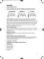
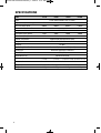
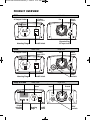
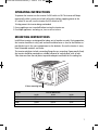
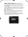
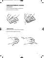
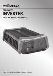
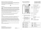
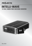
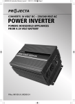
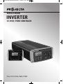
IP150-1000 Instruction Manual_1 3/02/12 11:01 AM Page 1
INTELLI-WAVE
INVERTER
12 VOLT, PURE SINE WAVE
P/No.s IP150, IP300, IP600, IP1000
IP150-1000 Instruction Manual_1 3/02/12 11:01 AM Page 2
IMPORTANT SAFETY INFORMATION
Please read this manual thoroughly before use and store in a safe place for future reference.
WARNINGS
• For indoor use out of weather only.
• For use with negatively earthed vehicles & systems only.
• Internally bonded for safety, battery DC negative to case & AC socket earth.
• Hazardous voltage inside – do not attempt to open, repair or use if damaged.
• Only connect 230/240V AC appliances that are in safe condition.
• This appliance is not intended for use by young children or infirm persons unless they
have been adequately supervised by a responsible person to ensure that they can use
the appliance safely.
• Young children should be supervised to ensure that they do not play with the appliance.
• It is recommended that a type ‘A’ portable residual current device (RCD) be used for
added output protection.
• For independent use, do not connect to buildings.
CAUTIONS
• Batteries should be mounted in a separate well-vented enclosure.
• Even though the inverter is powered from a battery, it still produces dangerous high
voltage AC power and has the potential to fatally injure if incorrectly installed or used.
• Double check battery negative and positive posts before making any connection; a wrong
connection (reverse polarity) will cause the fuse/s to blow and may damage the inverter.
• A small spark (arc) can occur when making the final battery connection, this is most
common when the inverter has not been used for some time. This spark is caused by the
inverter’s large capacitors charging quickly. To minimise this, make the last connection
quickly and completely.
• Batteries can be dangerous; follow all battery manufacturer’s instructions and warnings.
• Never operate the inverter without the DC negative input connected direct to the
battery and never install a fuse, circuit breaker or battery switch in the negative supply
line (IP150 excepted).
2
IP150-1000 Instruction Manual_1 3/02/12 11:01 AM Page 3
FEATURES
PURE SINE WAVE OUTPUT
There are two different types of inverters, modified sine wave and pure sine wave.
The difference between the two is how closely the output replicates mains power.
Logically it follows that the process used in a pure sine wave inverter is more complex
than a modified sine wave inverter and subsequently more expensive. Most electric
appliances operate unaffected on a modified sine wave and hence they are more common.
Pure sine wave inverters are best for use on medical equipment and sensitive electrical
appliances. They allow you to watch television without static, play your favourite game
on an XBoxTM, PlaystationTM or WiiTM and run a fluoro, all of which may not operate
properly on a modified sine wave inverter.
FULLY ISOLATED DESIGN
Safety is paramount around 240V and in particular with inverters which is why Projecta
fully electrically isolates the DC (and therefore battery posts, vehicle chassis, etc) from
the 240V AC circuit.
DESIGNED TO AS4763
Designed in accordance with Australian Standard AS4763 (Int): 2006 – Safety of
Portable Inverters.
REMOTE CONTROL DISPLAY (IP600 AND IP1000)
Control and monitor the inverter’s performance from a remote control display allowing
the inverter to be mounted flush or surface mounted out of sight. Ideal for use in
caravans, motor homes and boats.
BI-COLOUR L.E.D DISPLAY
THERMOSTATICALLY CONTROLLED COOLING FAN
•
•
•
•
•
PROTECTION
Low input voltage
High input voltage
Low battery alarm
Over temperature
Overload
3
IP150-1000 Instruction Manual_1 3/02/12 11:01 AM Page 4
SPECIFICATIONS
P/No.
IP150
Input
Input Current (Max DC Amps)
IP300
IP600
15A
30A
60A
100A
500mA
500mA
650mA
1200mA
–
–
2mA
2mA
Continuous Power (Watts)
150W
300W
600W
1000W
Peak Power (Watts)
300W
600W
1200W
2000W
No Load Current Draw
Remote Standby Current Draw
Output
240VAC 50Hz
Inverter Classification
Equipotentially Bonded Inverter (EPB)
Output Waveform
Pure Sine Wave
Efficiency
85–90%
Low Battery Alarm/Shutdown
Alarm 10.25V, Shutdown 9.75V (±0.2V)
Cooling Fan
Automatic Temperature Controlled
Thermal Shutdown
Replacement Fuse
Fuse Quantity & Size
65ºC (±5ºC)
30A
Standard Auto Blade
60A
110A
Size (mm)
Weight
220A
(1 x 30A)
(2 x 30A)
232 x 108 x 63
252 x 108 x 63
250 x 168 x 81
360 x 168 x 81
1.1kg
1.25kg
2.2kg
3.2kg
Fuse Location
4
IP1000
12VDC Battery/Vehicle (9.75–15.5VDC)
(2 x 40A & 1 x 30A) (4 x 40A & 2 x 30A)
Internal
IP150-1000 Instruction Manual_1 3/02/12 11:01 AM Page 5
PRODUCT OVERVIEW
IP150
FRONT VIEW
AC Output Socket
REAR VIEW
Bi-Colour
Status L.E.D
Fan
Chassis
Ground
150W Pure Sine Wave
STATUS
OFF
CHASSIS
GND
ON
12V DC
INPUT
AC OUTPUT
IP300
Cigarette Plug
DC Input Lead
On/Off Switch
Mounting Flange
FRONT VIEW
AC Output Socket
REAR VIEW
Fan
Bi-Colour
Status L.E.D
Chassis
Ground
300W Pure Sine Wave
STATUS
OFF
CHASSIS
GND
ON
+
AC OUTPUT
Mounting Flange
IP600 & IP1000
–
12VDC
Termianls
On/Off Switch
FRONT VIEW
LCD Screen
12V DC INPUT
REAR VIEW
AC Output
Socket
Remote
Input
Fan
Chassis
Ground
Pure Sine Wave
VOLTS
Display
Selection
Buttons
WATTS
LOAD%
AC OUTPUT
Mounting
Flange
CHASSIS
GND
REMOTE
OFF
+
ON
On/Off
Switch
12VDC INPUT
–
12VDC
Termianls
IP150-1000 Instruction Manual_1 3/02/12 11:01 AM Page 6
CONNECTING THE INVERTER
IP150
The IP150 is fitted with a lead and cigarette plug. Insert the plug into the vehicle’s
12V accessory socket and turn the inverter on. You may need to turn the vehicle’s
ignition to ‘accessory’ to supply power to the inverter.
IP300, IP600, IP1000
It is important to use suitable cable lengths and sizes to get the most out of your
inverter. Use of cable that is too thin or too long will result in voltage drop between
the battery and inverter, and may trigger low voltage warnings and inverter shutdowns.
It is recommended to place cable in corrugated conduit to protect from damage.
The following table lists suitable cable sizes for different cable lengths available
from Projecta.
Part Number (Description)
Cable Length
0–3m
3–6m
2
IP300
IWK1 (3m, 8mm )
IWK2 (6m, 26mm2)
IP600
IWK3 (3m, 32mm )
IWK4 (6m, 49mm2)
IP1000
IWK3 (3m, 32mm2)
IWK5 (6m, 64mm2)
2
1. Prepare all cable ends with cable lugs.
2. Install a circuit breaker or high current fuse and fuse holder in the positive line as close
to the battery as possible. The following fuses are available from Projecta:
IP300: IFB-40 (40A fuse and holder)
IP600: IFB-100 (100A fuse and holder)
IP1000: IFB-150 (150A fuse and holder)
3. Make sure the inverter On/Off switch is turned OFF.
4. Connect the cables to the DC input terminals on the rear of the inverter.
The red terminal is positive (+) and the black terminal is negative (-).
a. Connect the positive cable to the inverter and battery positive terminals.
b. Connect the negative cable to the inverter and battery negative terminals.
5. The inverter is earthed through the negative DC input cable. Additional earthing can be
made by connecting an insulated wired from the chassis-ground terminal at the rear of
the inverter to the vehicle’s chassis or any other ground point.
FUSE
CORRUGATED CONDUIT
Intelli-Wave
6
IP150-1000 Instruction Manual_1 3/02/12 11:01 AM Page 7
OPERATING INSTRUCTIONS
To operate the inverter turn the inverter On/Off switch to ON. The inverter will beep
momentarily while it carries out a brief self-analysis before supplying power to the
AC socket. To turn off, turn the inverter On/Off switch to OFF.
To help prevent the inverter being overloaded:
1. Ensure appliances are turned off before turning the inverter on.
2. If multiple appliances are being run, turn on one at a time.
MOUNTING INSTRUCTIONS
Intelli-Wave inverters are designed for indoor, out of weather use only. During operation,
the inverter should be in a dry, cool and well-ventilated area as close to the batteries as
possible, but not in the same compartment as the batteries. Ensure the inverter is away
from flammable materials and fumes.
The inverter end plates include a mounting flange for easy mounting. If permanently fixed,
the inverter should be mounted to a suitable horizontal or vertical panel, with at least
10cm clearance from the end plates to provide adequate ventilation for the cooling fan.
300W Pu
re Sine W
ave
STATUS
OFF
AC OUTP
UT
ON
3.5mm mounting hole
Part No.
Length
Inverter Dimensions
Width
Height
IP150
232mm
108mm
63mm
IP300
252mm
108mm
63mm
IP600
250mm
168mm
81mm
IP1000
360mm
168mm
81mm
7
IP150-1000 Instruction Manual_1 3/02/12 11:01 AM Page 8
UNDERSTANDING YOUR INVERTER
A) IP150 & IP300
These inverters are equipped with a bi-colour status L.E.D and audible alarm. During
normal operation, the L.E.D will illuminate solid green. In the event of a fault or error,
the alarm will sound and the L.E.D will illuminate various signals.
STATUS
L.E.D SIGNAL
Normal
Green
ALARM
–
Low Battery Voltage
Green
Low Battery Voltage Shutdown
Green/Red (Flashing)
ON
Over Temperature Shutdown
and Output Short Circuit
Red
ON
Overload Shutdown
Red (Flashing)
ON
High Battery Voltage Shutdown
Green (Flashing)
ON
/
ON
B) IP600 & IP1000
These inverters are equipped with an audible alarm and a multi-function LCD screen
with selection buttons allowing you to monitor the inverter’s performance. During
normal operation, the LCD screen will default to the VOLTS display (input battery
voltage). Alternative information can be displayed by pressing the relevant buttons:
VOLTS: Displays input battery voltage
WATTS: Displays the amount of power being drawn by the appliance (in Watts)
LOAD %: Indicates the percentage of total capacity being drawn by the appliance
In the event of a fault or error, the alarm will sound and the LCD screen will display
one of several fault codes.
8
STATUS
CODE
Normal
–
REMOTE L.E.D SIGNAL
Green
ALARM
–
Low Battery Voltage
Low Battery
Voltage Shutdown
Over Temperature
Shutdown
Output Short Circuit
Overload Shutdown
High Battery
Voltage Shutdown
Lb
Green
ON
Lb
Green/Red (Flashing)
/
ON
OTP
OSP
OPP
Red
Red
Red (Flashing)
ON
ON
ON
Hb
Green (Flashing)
ON
IP150-1000 Instruction Manual_1 3/02/12 11:01 AM Page 9
REMOTE CONTROL DISPLAY (IP600 & IP1000 ONLY)
To install the remote control, insert the data plug into the data socket at the rear of the
inverter. To operate the inverter using the remote, the inverter On/Off switch
must be turned to ON.
The remote is equipped with an LCD screen identical to the inverter, as well a bi-colour
status L.E.D and audible alarm. During normal operation, the LCD screen will default to
the VOLTS display (input battery voltage). Alternative information can be displayed by
pressing the relevant buttons:
VOLTS: Displays input battery voltage
WATTS: Displays the amount of power being drawn by the appliance (in Watts)
LOAD %: Indicates the percentage of total capacity being drawn by the appliance
OFF/ON: Turns the inverter on and off (stand by mode)
In the event of a fault or error, the alarm will sound, the LCD screen will display one
of several fault codes and L.E.D will illuminate various signals. Refer to the table on
the previous page (IP600 & IP1000) for fault codes and L.E.D signals.
9
IP150-1000 Instruction Manual_1 3/02/12 11:01 AM Page 10
MOUNTING REMOTE CONTROL
FLUSH MOUNT
• Cut a 93mm x 70mm hole into the desired mounting surface to suit the supplied
mounting plate.
• Position the mounting plate into the hole with the side labelled ‘FLUSH MOUNT’
facing outwards and screw the supplied screws into the mounting surface as per
the below illustration.
FLU
OU
SH M
NT
• Clip the remote control into the mounting plate.
ER
ON
POW
LK
BU RGE
A
CH
B
SOR
AB
FLU
Y
FULLRGED
A
CH
SH
MOU
N
CO
RE
NT
E
YP
TT
BA
GE
AR
CH
P
M
LT/A
VO
SURFACE MOUNT
• Position the supplied mounting plate onto the desired mounting surface so the side
labelled ‘SURFACE MOUNT’ is facing outwards and screw the supplied screws into
the mounting surface as per the below illustration.
• Drill a 15mm cable exit hole into the mounting surface, ensure cable exit hole is
positioned directly in the middle of the mounting plate.
• Position the remote control into the remote control surround as per the below
illustration and clip into the mounting plate.
ER ON
POW
BULK GE
R
CHA
ORB
ABS
SU RF
OU NT
AC E M
Y
FULL GED
R
CHA
C
E
YP
TT
BA
GE
AR
CH
P
M
LT/A
VO
10
ON
RE
IP150-1000 Instruction Manual_1 3/02/12 11:01 AM Page 11
REMOVING REMOTE CONTROL
FLUSH MOUNT
1. Pull the remote control sideways and firmly lift
2. The remote will click out of place
R ON
POWE
BULK GE
CHAR
BULK GE
CHAR
RB
ABSO
RB
ABSO
FULLYGED
CHAR
Y
FULL GED
CHAR
N
AMP
GE
CHAR
RECO
PE
BAT TY
VOLT/
ON
REC
BAT
TYPE
GE
AR
CH
MP
LT/A
VO
SURFACE MOUNT
1. Holding the remote on either side, push upwards.
2. Squeeze the sides together to lift away.
POW
ER
ON
POW
ER
ON
11
IP150-1000 Instruction Manual_1 3/02/12 11:01 AM Page 12
FAULTS & ERRORS
Problem
Low battery voltage
Possible Cause
Input battery voltage
is below 10.5V
Low battery Shutdown
a) The input battery voltage
is below 10V
b) There is a voltage drop
between the battery and
the inverter
a) Recharge battery immediately.
Failure to do so may cause
permanent battery damage
b) Check cable connections and
that cable sizes are sufficient
(see pg 6)
Over temperature shutdown
Internal temperature
is above 65ºC
Turn off inverter and allow to cool
Overload shutdown
The inverter is overloaded:
a) there are too many appliances
running, or
b) the appliance is not suitable
for this inverter
Turn off inverter to reset. Check the
(combined) power usage of the
appliance/s is suitable for this inverter
High battery shutdown
Input battery voltage
is above 15.5V
a) Confirm input battery is 12V.
b) Check that a battery charger is
not connected to the battery
Output short circuit
Appliance may have an
electrical fault
Remove appliance and have it
checked by a qualified technician
12
Solution
a) Recharge battery
b) Battery may be too small.
Refer to pg 13 for recommended
battery sizes
c) Check cable connections and that
cable sizes are sufficient (see pg 6)
IP150-1000 Instruction Manual_1 3/02/12 11:01 AM Page 13
UNDERSTANDING YOUR POWER REQUIREMENTS
POWER REQUIREMENTS OF YOUR APPLIANCE/S:
All appliances have a rating plate that shows the amount of power (Watts) used or the
current (Amps) drawn under normal use.
The following table shows the maximum combined AC Watts or AC Amps which can
be run by the inverter.
P/No.
IP150
IP300
IP600
IP1000
AC Combined maximum load (Watts)
150W
300W
600W
1000W
AC Combined maximum load (Amps)
0.6A
1.2A
2.4A
4.0A
Some appliances that use an electric motor or transformer may draw up to 10 times
their power rating when first turned on. These are called inductive loads and are
the most difficult for the inverter to run. Contact your appliance manufacturer for
further advice.
SUITABLE POWER SOURCE
In order to operate the inverter and supply power to an appliance a suitable 12V DC
power supply is required, typically a vehicle or caravan battery, portable power pack
or an independent 12V lead acid battery. For most applications, a deep cycle battery
is recommended for best performance.
The size of the battery used will determine how long the inverter will supply power
to an appliance and how well the inverter will perform. Most batteries are marked with
their size in Amp hours (Ah) or Cold Cranking Amps (CCA).
Because 12V inverters are capable of drawing high currents the inverter should only be
connected to a suitable size battery. Connection to an undersized battery could damage
the battery and will result in the inverter shutting down within a short period due to
low battery voltage.
The amount of power drawn from the battery is proportional to the inverter load.
P/No.
Minimum recommended
battery size
Run time with maximum load
and minimum battery size
Run time for a 100W globe
with minimum battery size
Ideal battery size
IP150
IP300
IP600
IP1000
17Ah
(100CCA)
24Ah
(200CCA)
50Ah
(400CCA)
75Ah
(550CCA)
40 min
40 min
30 min
15 min
80 min
2 hours
4 hours
6 hours
50–70Ah
50–70Ah
50–130Ah
75–250Ah
13
IP150-1000 Instruction Manual_1 3/02/12 11:01 AM Page 14
TROUBLESHOOTING/FAQ:
Q. Why does the inverter turn itself off?
A. If the inverter’s audible alarm sounds and a fault L.E.D illuminates, this indicates that
there is a fault or error, and the inverter may turn off. Most commonly this would be
caused by an appliance that is drawing too much power (overloading), low battery
voltage or voltage drop due to insufficient size cables or poor connections (refer to
‘Faults & Errors’ table, page 12).
Q. The Inverter will not run my appliance even though the appliance draws less
power (Watts) than the size of the inverter?
A. Electrical appliances can be divided into three groups by the way they draw energy
(current) from their power supply. These groups are “Resistive”, “Inductive” and
“Capacitive” appliances or also called “loads”. Some appliances may draw all three
types of power.
Resistive Loads such as normal incandescent lights (wire filament) always draw
a constant power (watts) from the power supply, that is a 100 Watt light will draw
approximately 100 Watts from the power supply at all times. Resistive loads are the
easiest appliances for an inverter to run.
Inductive Loads such as a refrigerator (Electric Motor) require a large rush of power
(surge current) to start and then usually draw a more constant power once running.
Inductive loads contain coils of wire (motors, transformers, ballasts, solenoids). When
the power is first turned on, these coils of wire draw a large surge current which forms
the magnetic flux (magnetic field) which allows these appliances to work. This magnetic
flux is a kind of stored energy.
The most common inductive appliances are: fridges, air compressors, transformers/
chargers, pumps, power tools and fluorescent lights. These appliances can draw up to
10 times their normal running power to start up; that is to run a 80W fridge you may
need a 600 or 1000 Watt inverter.
Capacitive Loads such as many TV’s or many electronic appliances require a large surge
current to start only when they have not been used for a while. This is often due to large
capacitors in the power supply that must be quickly charged when the appliance is turned
on. If the appliance is not used for a few days these capacitors slowly go flat. Resetting
the inverter a couple of times may allow these appliances to work.
There are some appliances such as large refrigerators, air conditioners and other pump
driven appliances that have extremely high start up currents, because they have an
inductive motor that must start under load. These appliances are not recommended
for use with an inverter. They should be powered by an engine driven generator.
14
IP150-1000 Instruction Manual_1 3/02/12 11:01 AM Page 15
Q. Why does it damage the inverter if the battery leads are reverse-connected?
A. Your inverter uses sophisticated electronics to convert DC battery power to AC mains
power. If you accidentally connect the inverter to the battery incorrectly (reverse
polarity) a large current will be drawn by the inverter which will blow the protection
fuse. As this occurs some of the high current could damage sensitive electronic
components. Because of this risk it is important to always double-check the battery
polarity before making any connections.
Q. How do I check or change the fuses?
A. Intelli-Wave inverters contain internal fuses and should only be checked or replaced
by a qualified electrical appliance repairer.
THE DC SUPPLY MUST BE DISCONNECTED BEFORE ANY REPAIR, THEN TURN THE
ON/OFF SWITCH OF THE INVERTER “ON” TO DISCHARGE THE CAPACITORS.
Q. Why does the fan only operate sometimes?
A. Intelli-Wave inverters feature a temperature controlled automatic cooling fan that only
operates when needed. This allows the inverter to run very quietly for most of the time.
Q. Can I run laptop computers and other sensitive electrical appliances?
A. Yes. Intelli-Wave’s pure sine wave output is suitable for medical equipment and
sensitive electrical appliances. They allow you to watch television without static,
operate computers and gaming consoles and run fluorescent lights.
15
IP150-1000 Instruction Manual_1 3/02/12 11:01 AM Page 16
WARRANTY STATEMENT
Applicable only to product sold in Australia
Brown & Watson International Pty Ltd of 1500 Ferntree Gully Road, Knoxfield, Vic.,
telephone (03) 9730 6000, fax (03) 9730 6050, warrants that all products described in its
current catalogue (save and except for all bulbs and lenses whether made of glass or some
other substance) will under normal use and service be free of failures in material and
workmanship for a period of one (1) year (unless this period has been extended as
indicated elsewhere) from the date of the original purchase by the consumer as marked on
the invoice. This warranty does not cover ordinary wear and tear, abuse, alteration of
products or damage caused by the consumer.
To make a warranty claim the consumer must deliver the product at their cost to the
original place of purchase or to any other place which may be nominated by either BWI or
the retailer from where the product was bought in order that a warranty assessment may
be performed. The consumer must also deliver the original invoice evidencing the date and
place of purchase together with an explanation in writing as to the nature of the claim.
In the event that the claim is determined to be for a minor failure of the product then BWI
reserves the right to repair or replace it at its discretion. In the event that a major failure is
determined the consumer will be entitled to a replacement or a refund as well as
compensation for any other reasonably foreseeable loss or damage.
This warranty is in addition to any other rights or remedies that the consumer may have
under State or Federal legislation.
IMPORTANT NOTE
Our goods come with guarantees that cannot be excluded under the Australian Consumer
Law. You are entitled to a replacement or refund for a major failure and compensation for
any other reasonably foreseeable loss or damage. You are also entitled to have the goods
repaired or replaced if the goods fail to be of acceptable quality and the failure does not
amount to a major failure.
Distributed by
AUSTRALIA
Brown & Watson International Pty Ltd
Knoxfield, Victoria 3180
Telephone (03) 9730 6000
Facsimile (03) 9730 6050
National Toll Free 1800 113 443
NEW ZEALAND
Narva New Zealand Ltd
22–24 Olive Road
PO Box 12556 Penrose
Auckland, New Zealand
Telephone (09) 525 4575
Facsimile
(09) 579 1192
IS173
Issue 1 25.01.12