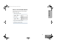
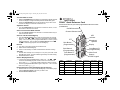
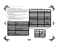
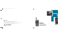
1
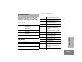
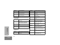
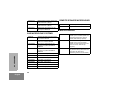
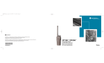
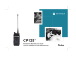
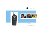
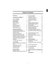
96C23-C_cvr.qxd
7/20/2005
4:30 PM
Page 1
MOTOROLA and the Stylized M Logo are registered in the US Patent & Trademark Office.
All other product or service names are the property of their respective owners.
© Motorola, Inc. 2005. All rights reserved. Printed in U.S.A.
MOTOROLA et le logotype au M stylisé sont enregistrés auprès du Bureau des marques et brevets des États-Unis.
Tous les autres noms de produits et de services sont la propriété de leurs titulaires respectifs.
© Motorola, Inc. 2005. Tous droits réservés. Imprimé aux États-Unis.
PR400™
Commercial Series
*6881096C23*
Two-Way Radio User Guide
6881096C23-C
de la radio bidirectionnelle
Manuel de l'utilisateur
COMPUTER SOFTWARE
COPYRIGHTS
The Motorola products described in this
manual may include copyrighted Motorola
computer programs stored in semiconductor
memories or other media. Laws in the United
States and other countries preserve for
Motorola certain exclusive rights for
copyrighted computer programs including, but
not limited to, the exclusive right to copy or
reproduce in any form the copyrighted
computer program. Accordingly, any
copyrighted Motorola computer programs
contained in the Motorola products described
in this manual may not be copied, reproduced,
modified, reverse-engineered, or distributed in
any manner without the express written
permission of Motorola. Furthermore, the
purchase of Motorola products shall not be
deemed to grant either directly or by
implication, estoppel, or otherwise, any license
under the copyrights, patents or patent
applications of Motorola, except for the normal
non-exclusive license to use that arises by
operation of law in the sale of a product.
CONTENTS
Computer Software Copyrights . . . inside cover
Safety . . . . . . . . . . . . . . . . . . . . . . . . . . . . . . 5
Introduction . . . . . . . . . . . . . . . . . . . . . . . . . 7
Conventional Radio Systems . . . . . . . . . . . .
Trunked Radio Systems . . . . . . . . . . . . . . . .
LTR Trunked Systems . . . . . . . . . . . . . . .
PR400 Radio Features . . . . . . . . . . . . . . . . .
Radio-Wide Features . . . . . . . . . . . . . . . .
LTR Trunked Features. . . . . . . . . . . . . . .
Conventional Signaling Features . . . . . . .
7
7
7
8
8
8
8
Radio Overview . . . . . . . . . . . . . . . . . . . . . 11
Accessory Information. . . . . . . . . . . . . . . . .
Attach the Battery . . . . . . . . . . . . . . . . .
Remove the Battery . . . . . . . . . . . . . . . .
Attach the Antenna . . . . . . . . . . . . . . . .
Remove the Antenna . . . . . . . . . . . . . . .
Attach the Belt Clip . . . . . . . . . . . . . . . .
Remove the Belt Clip . . . . . . . . . . . . . . .
Battery Information . . . . . . . . . . . . . . . . . . .
Charging Your Battery . . . . . . . . . . . . . .
12
12
12
13
13
14
14
15
15
CONTENTS
Product Safety and RF Exposure
Compliance . . . . . . . . . . . . . . . . . . . . . . . . . 5
Wall Charger. . . . . . . . . . . . . . . . . . . . . . . . . 16
Desktop Chargers. . . . . . . . . . . . . . . . . . . . . 16
Rapid Charger . . . . . . . . . . . . . . . . . . . . . 16
Slow Charger. . . . . . . . . . . . . . . . . . . . . . 17
Battery Charge Status . . . . . . . . . . . . . . . . . 18
LED Indicator . . . . . . . . . . . . . . . . . . . . . . . . 18
Display . . . . . . . . . . . . . . . . . . . . . . . . . . . . . 19
DTMF Keypad . . . . . . . . . . . . . . . . . . . . . . . 20
Indicator Tones. . . . . . . . . . . . . . . . . . . . . . . 21
Programmable Buttons. . . . . . . . . . . . . . . . . 22
Menu Buttons . . . . . . . . . . . . . . . . . . . . . . . . 26
Menu Button . . . . . . . . . . . . . . . . . . . . . . 26
Menu Scroll Buttons . . . . . . . . . . . . . . . . 26
Navigate the Menu . . . . . . . . . . . . . . . . . 26
Exit the Menu . . . . . . . . . . . . . . . . . . . . . 26
Getting Started . . . . . . . . . . . . . . . . . . . . . . 27
Turn the Radio On or Off . . . . . . . . . . . . . . . 27
Adjust the Volume . . . . . . . . . . . . . . . . . . . . 27
Select an LTR Channel/Talkgroup . . . . . . . . 28
Select a Conventional Radio Channel . . . . . 28
Receive a Conventional or LTR Call . . . . . . 28
Monitor . . . . . . . . . . . . . . . . . . . . . . . . . . . . . 29
Permanent Monitor . . . . . . . . . . . . . . . . . 29
Transmit an LTR Call . . . . . . . . . . . . . . . . . . 30
Transmit a ConventionalCall . . . . . . . . . . . . 30
Call Light (Trunked Operation Only). . . . . . . 31
1
English
CONTENTS
EnglishTOC.fm Page 2 Friday, August 6, 2004 3:58 PM
Repeater or Talkaround Mode . . . . . . . . . . .31
Revert Memory Channel (1 & 2) . . . . . . . . . .32
Store Memory Channel (1 & 2) . . . . . . . . . . .32
Home Revert AutoKey (1 & 2) . . . . . . . . . . .32
VOX Operation . . . . . . . . . . . . . . . . . . . . . . .32
Connecting a VOX Headset . . . . . . . . . .32
Enable or Disable VOX . . . . . . . . . . . . . .32
Enable/Disable Headset Sidetone . . . . . . . .33
VOX Headset. . . . . . . . . . . . . . . . . . . . . .33
Non-VOX Headset with In-Line PTT . . . .33
Keypad Lock/Unlock . . . . . . . . . . . . . . . . . . .34
Program PL/DPL Codes . . . . . . . . . . . . . . . .34
Radio Calls . . . . . . . . . . . . . . . . . . . . . . . . .35
Selective Radio Inhibit . . . . . . . . . . . . . . . . .35
Receive a Selective Call
(Conventional Operation Only) . . . . . . . . . .35
Send a Selective Call
(Conventional Operation Only) . . . . . . . . . .35
Receive a Call Alert™ Page
(Conventional Operation Only) . . . . . . . . . .36
Send a Call Alert Page
(Conventional Operation Only) . . . . . . . . . .36
Repeater Access . . . . . . . . . . . . . . . . . . . . .37
Radio Check . . . . . . . . . . . . . . . . . . . . . . . . .37
2
English
Scan. . . . . . . . . . . . . . . . . . . . . . . . . . . . . . . 39
Talkback. . . . . . . . . . . . . . . . . . . . . . . . . . . . 39
Start System Scan . . . . . . . . . . . . . . . . . . . 39
Stop System Scan . . . . . . . . . . . . . . . . . . . . 40
Start Auto Scan . . . . . . . . . . . . . . . . . . . . . . 40
Stop Auto Scan . . . . . . . . . . . . . . . . . . . . . . 40
Delete a Nuisance Channel/Talkgroup . . . . 41
Restore Channels/Talkgroups to the
Scan List . . . . . . . . . . . . . . . . . . . . . . . 41
Edit a Scan List . . . . . . . . . . . . . . . . . . . . . . 42
Add or Delete Channels/Talkgroups in a
Scan List . . . . . . . . . . . . . . . . . . . . . . . . . . 42
Prioritize a Channel or Talkgroup in a
Scan List . . . . . . . . . . . . . . . . . . . . . . . . . . 43
Phone . . . . . . . . . . . . . . . . . . . . . . . . . . . . . 45
Access the Repeater . . . . . . . . . . . . . . . . . . 45
Receive a Phone Call. . . . . . . . . . . . . . . . . . 45
Disconnect a Phone Call . . . . . . . . . . . . . . . 46
Make a Phone Call. . . . . . . . . . . . . . . . . . . . 46
Edit the Phone List . . . . . . . . . . . . . . . . . . . . 48
Add an Entry . . . . . . . . . . . . . . . . . . . . . . 48
Delete an Entry . . . . . . . . . . . . . . . . . . . . 49
Edit an Entry . . . . . . . . . . . . . . . . . . . . . . 49
Edit Access/Deaccess Codes . . . . . . . . . 50
EnglishTOC.fm Page 3 Friday, August 6, 2004 3:58 PM
Tone Preferences . . . . . . . . . . . . . . . . . . . 51
53
53
CONTENTS
Tones On/Off. . . . . . . . . . . . . . . . . . . . . . . .
Keypad On/Off Tones . . . . . . . . . . . . . . . . .
Call Tone Tagging (Conventional
Operation Only). . . . . . . . . . . . . . . . . . . . .
Escalert (Conventional
Operation Only). . . . . . . . . . . . . . . . . . . . .
54
54
User Settings . . . . . . . . . . . . . . . . . . . . . . . 55
Set Squelch Level . . . . . . . . . . . . . . . . . . . .
Set Power Level . . . . . . . . . . . . . . . . . . . . .
Option Board On/Off . . . . . . . . . . . . . . . . . .
Set the Lights . . . . . . . . . . . . . . . . . . . . . . .
Display the Software Version . . . . . . . . . . .
57
57
58
58
59
Warranty. . . . . . . . . . . . . . . . . . . . . . . . . . . 61
Accessories . . . . . . . . . . . . . . . . . . . . . . . . 65
Antennas . . . . . . . . . . . . . . . . . . . . . . . . . . .
Batteries . . . . . . . . . . . . . . . . . . . . . . . . . . .
Carry Accessories . . . . . . . . . . . . . . . . . . . .
Chargers . . . . . . . . . . . . . . . . . . . . . . . . . . .
Headsets . . . . . . . . . . . . . . . . . . . . . . . . . . .
Surveillance Accessories . . . . . . . . . . . . . .
Ear Microphone Systems . . . . . . . . . . . . . .
Remote Speaker Microphones . . . . . . . . . .
Miscellaneous . . . . . . . . . . . . . . . . . . . . . . .
65
65
65
66
66
67
68
68
68
3
English
EnglishTOC.fm Page 4 Monday, August 16, 2004 1:34 PM
CONTENTS
Notes:
4
English
00_SafetyNA.fm Page 5 Monday, August 16, 2004 1:32 PM
SAFETY
PRODUCT SAFETY AND RF
EXPOSURE COMPLIANCE
!
Caution
Before using this product, read the
operating instructions for safe usage
contained in the Product Safety and
RF Exposure booklet enclosed with
your radio.
ATTENTION!
SAFETY
This radio is restricted to occupational use
only to satisfy FCC RF energy exposure
requirements. Before using this product, read
the RF energy awareness information and
operating instructions in the Product Safety
and RF Exposure booklet enclosed with your
radio (Motorola Publication part number
68P81095C98) to ensure compliance with RF
energy exposure limits.
For a list of Motorola-approved antennas,
batteries, and other accessories, visit the
following web site which lists approved
accessories: http://www.motorola.com/cgiss/
index.shtml.
5
English
00_SafetyNA.fm Page 6 Monday, August 16, 2004 1:32 PM
SAFETY
Notes:
6
English
INTRODUCTION
Your PR400™ radio can operate on both LTR®
trunked and conventional radio systems. This
radio combines the very latest in two-way
technology while delivering outstanding
functionality at the touch of a button.
CONVENTIONAL RADIO SYSTEMS
Conventional typically refers to radio-to-radio
communications through a single channel.
Conventional systems also allow radio users to
extend communication coverage by relaying
their messages through a repeater. To ensure
coordinated use by multiple users, each radio
user must monitor the channel or repeater
before transmitting to verify that the system is
not currently busy.
A trunked radio system allows a large number
of users to share a relatively small number of
frequencies or repeaters without interfering
with each other. The airtime of all the repeaters
in a trunked system is pooled, which
maximizes the amount of airtime available to
Some of the benefits of trunked two-way radio
systems are:
•
•
•
•
No channel/talkgroup monitoring required prior
to transmission
Improved system access
Automatic channel/talkgroup selection
Increased privacy among members of the same
group
LTR Trunked Systems
LTR (Logic Trunked Radio) is a transmissionbased trunking protocol developed by the E. F.
Johnson Company for primarily single-site
trunking applications. In transmission trunking,
a repeater is used for only the duration of a
single transmission. Once a transmission is
completed, that repeater becomes available to
other users. This means that a conversation
comprised of many transmissions may occur
over several different channels/talkgroups
within the LTR system. This method of trunking
provides system efficiency by making
repeaters available to all users after every
transmission.
INTRODUCTION
TRUNKED RADIO SYSTEMS
any one radio and minimizes channel/
talkgroup congestion.
When an LTR trunked radio user wants to
communicate with another radio, the user’s
7
English
radio sends a “channel/talkgroup request” to
the home repeater. The system then sends
back a “channel/talkgroup grant” to the user’s
radio. The channel/talkgroup grant message
contains the number of a “go to” repeater to tell
the radio which repeater to use. This “go to”
repeater can be the same as the radio’s home
repeater or another repeater in the system.
The radio uses the “go to” repeater for
transmission. Once the transmission has
ended, this repeater is available for other
users.
PR400 RADIO FEATURES
•
•
•
LTR Trunked Features
•
INTRODUCTION
•
•
•
8
English
64 Conventional Channels
Up to 10 Sites and 100 Talkgroups
Up to 20 Repeaters per Site
8-Character Alphanumeric Display
4 Programmable Feature Buttons
2 Memory Channels
Telephone Interconnect
User-programmable Phone, Scan, and TPL/
DPL Lists
Option Board Expandability
Busy Channel Lockout
High/Low Power Settings
MDC 1200 Signaling
- Selective Radio
Inhibit Decode
- Radio Check
Decode
- MDC Pre-Time
- PTT ID Encode/
Decode
- DOS
Conventional Signaling Features
•
MDC 1200 Signaling
- Selective Radio
Inhibit Decode
Radio-Wide Features
•
•
•
•
•
•
•
•
Transmit Time-Out Timer
Monitor and Sticky Permanent Monitor
System Scan with 2 Priority Levels and Revert
Scan
•
- PTT ID Encode/
Decode
Quik-Call II Signaling
- Call Alert
Encode/Decode
- Selective Call
Encode/Decode
- Radio Call List
- Call Tone
Tagging
•
DTMF Signaling
- DTMF PTT ID
Encode
- DTMF Call Alert
Encode
- DTMF
Selective Call
Encode
INTRODUCTION
9
English
INTRODUCTION
Notes:
10
English
01_Overview.fm Page 11 Monday, August 16, 2004 1:36 PM
Antenna
On/Off/Volume
Knob
Belt
Clip
Channel Selector
Knob
Push-to-Talk
(PTT) Button
RADIO OVERVIEW
RADIO OVERVIEW
LED Indicator
Microphone/
Speaker
Side Button 1
(programmable)
Display
Front Button P2
(programmable)
P2
P1
Side Button 2
(programmable)
1
4
Front Button P1
(programmable)
Menu Scroll
Buttons
3
2
7
5
8
6
9
#
0
Accessory Connector
with a Dust Cover
*
DTMF
Keypad
11
English
RADIO OVERVIEW
01_Overview.fm Page 12 Monday, August 16, 2004 1:36 PM
ACCESSORY INFORMATION
Remove the Battery
Attach the Battery
Locked
Unlocked
Battery Latch
1
Align the battery to the battery rails on the
back of the radio (approximately 1/2 in. from
the top of the radio.)
2
Press the battery firmly to the radio and slide the
battery upward until the latch snaps into place.
3
Slide the battery latch, located on radio bottom,
into the lock position.
12
English
1
Turn off the radio if it is turned on (see page 27).
2
Slide the battery latch into the unlock position.
Disengage by pushing downward and holding
the latch towards the front of the radio.
3
With the battery latch disengaged, slide the
battery down from the top of the radio about
1/2 in. Once the battery is free from the
battery rails, lift it directly away from the radio.
01_Overview.fm Page 13 Monday, August 16, 2004 1:36 PM
Attach the Antenna
Remove the Antenna
RADIO OVERVIEW
Turn the antenna clockwise to attach it.
Turn the antenna counter-clockwise to remove
it.
13
English
01_Overview.fm Page 14 Monday, August 16, 2004 1:36 PM
Remove the Belt Clip
RADIO OVERVIEW
Attach the Belt Clip
Belt Clip Tab
1
Align the grooves of the belt clip with those of
the battery.
1
Use a key to press the belt clip tab away from
the battery to unlock the belt clip.
2
Press the belt clip downward until you hear a
click.
2
Slide the belt clip upward to remove it.
14
English
01_Overview.fm Page 15 Monday, August 16, 2004 1:36 PM
Charging Your Battery
This radio is powered by a nickel-cadmium
(NICd), a nickel-metal hydride (NiMH), or a
lithium-ion (Li-lon) rechargeable battery.
Charge the battery before use to ensure
optimum capacity and performance. The
battery was designed specifically to be used
with a Motorola charger. Charging in nonMotorola equipment may lead to battery
damage and void the battery warranty.
Note:
When charging a battery attached to a radio,
turn the radio off to ensure a full charge.
If a battery is new, or its charge level is very
low, you will need to charge it before you can
use it. When the battery level is low and the
radio is in transmit mode you will see the LED
indicator flash red. Upon release of the PTT
button, you will hear an alert tone.
Note:
Batteries are shipped uncharged from the
factory. Always charge a new battery 14 to 16
hours before initial use, regardless of the
status indicated by the charger.
Note:
Do not use the wall charger and desktop
charger at the same time when charging.
RADIO OVERVIEW
BATTERY INFORMATION
The battery should be at about 77°F (25°C)
(room temperature), whenever possible.
Charging a cold battery (below 50° F [10°C])
may result in leakage of electrolyte and
ultimately in failure of the battery. Charging a
hot battery (above 95°F [35°C]) results in
reduced discharge capacity, affecting the
performance of the radio. Motorola rapid-rate
battery chargers contain a temperaturesensing circuit to ensure that batteries are
charged within the temperature limits stated
above.
15
English
RADIO OVERVIEW
01_Overview.fm Page 16 Monday, August 16, 2004 1:36 PM
WALL CHARGER
Note:
To Charge the Battery:
1
Turn the radio off.
2
Lift the dust cover to expose the audio
accessory connector.
3
Insert the charging adapter into the accessory
connector.
4
Plug the charging adapter into an electrical
outlet.
•
The LED on the charging adapter lights
Red while the charger is plugged into an
electrical outlet.
Note:
16
English
5
Do not use the wall charger if using lithiumion (Li-Ion) or nickel-metal hydride (NiMH)
batteries. The wall charger is for a nickelcadmium (NiCd) battery only.
Do not leave the charger connected to
the radio when it is not connected to
the electrical outlet.
Unplug the charger from the electrical outlet
and radio after 10 hours.
Note:
After the initial charge of 14 to 16
hours, do not charge the battery more
than 10 hours.
DESKTOP CHARGERS
Rapid Charger
1
Turn the radio off.
2
Place the battery, with or without the radio, in
the charger pocket.
•
The charger LED indicates the charging
progress.
LED color
Status
No LED Indication
Battery inserted incorrectly
or battery not detected.
Single Green Flash
Successful charger
power-up.
Flashing Reda
Battery unchargeable or not
making proper contact.
Steady Red
Battery is in Rapid charge
mode.
01_Overview.fm Page 17 Monday, August 16, 2004 1:36 PM
Flashing Yellow
Status
Battery in charger but waiting to be charged. The battery temperature may be too
hot or too cold. The voltage
may be lower than the predetermined threshold level
for charging.
authorized batteries. Other batteries may not
charge.
Slow Charger
Note:
Do not use the slow charger if using lithiumion (Li-Ion) or nickel-metal hydride (NiMH)
batteries. The slow charger is for a nickelcadmium (NiCd) battery only.
Flashing Greenb
Battery 90% (or more)
charged. Trickle charging.
1
Turn the radio off.
Green
Battery fully charged.
2
Place the battery, with or without the radio, in
the charger pocket.
a. Remove the battery from the charger and
use a pencil eraser to clean the three metal
contacts at the back of the battery. Place the
battery back into the charger. If the LED
indicator continues to flash red, replace the
battery.
b. A standard battery may require 90 minutes
to charge to 90% capacity. Even though new
batteries might prematurely indicate a full
charge (steady green LED), charge the
battery for 14 to 16 hours prior to initial use
for best performance.
•
RADIO OVERVIEW
LED color
The charger LED indicates the charging
progress.
LED color
Status
No LED Indication
Battery inserted incorrectly
or battery not detected.
Steady Red
Battery is in over night
charge mode. The battery is
fully charged after 11 hours.
A list of Motorola authorized batteries and
battery chargers appears on page 66. The
listed chargers will charge only Motorola
17
English
RADIO OVERVIEW
01_Overview.fm Page 18 Monday, August 16, 2004 1:36 PM
BATTERY CHARGE STATUS
LED INDICATOR
You can check battery charge status if your
dealer has preprogrammed one of the
programmable buttons. Hold down the
preprogrammed Battery Indicator button. The
charge status is shown on the display.
Indicates power-up, transmit, receive, scan
monitor status, channel/talkgroup busy, Call
Alert™ receive/transmit, Selective Call receive/
transmit, and battery status.
Battery
Level
Full
Good
Fair
Low
Very Low
LED State/Color
Indication
Radio Call
Display
Red
Transmitting
Flashing Red
Receiving
Flashing Red
Channel/Talkgroup Busy
Scan
Flashing Green
Scanning for activity
Call Alert
Flashing Yellow
Indicates receiving a Call Alert
Yellow
Indicates sending a Call Alert
Selective Call
Flashing Yellow
Indicates receiving a Selective
Call
Yellow
Indicates sending a Selective
Call
Monitor/Open Squelch
Yellow
While monitoring
Low Battery
Flashing Red
Low battery level
when transmitting
18
English
01_Overview.fm Page 19 Monday, August 16, 2004 1:36 PM
Symbol
PERS4
H
•Priority 1 Scan
The top display row displays menu and radio
status information:
Symbol
I
Signal Strength
B
Power Level
C
Monitor
D
Indication
The more bars, the stronger
the signal being received by
your radio.
Low Power “ R ” or High
Power “ S ” is activated.
The selected channel is being
monitored
Phone mode is selected.
Phone
G
Scan
(
•
flashing)
H
Priority 2 Scan
( steady)
•
J
Talkaround
F
Call Received
Indication
RADIO OVERVIEW
DISPLAY
Indicates scan has stopped
on an active Priority 1
channel/talkgroup.
Indicates scan has stopped
on an active Priority 2
channel/talkgroup.
Bypass the repeater and talk
directly to another radio.
A Selective Call or Call Alert
has been received.
B
Not Used
L
The keypad has been locked.
Keypad Lock
Indicates that the Scan
feature has been activated.
A
An Option Board has been
activated.
Option Board
19
English
RADIO OVERVIEW
01_Overview.fm Page 20 Monday, August 16, 2004 1:36 PM
DTMF KEYPAD
Number of Times Button is Pressed
2
3
1
/
\
2
A
B
C
2
The keypad is used for:
3
D
E
F
3
•
Dialing a phone number.
4
G
H
I
4
•
Entering information when programming phone
lists.
5
J
K
L
5
•
Accessing a repeater.
6
M
N
O
6
•
Each key can generate several different
characters. For example, to enter the character
“C,” press the 2 button three times. (Refer to
the following table.)
7
P
Q
R
S
8
T
U
V
8
9
W
X
Y
Z
*
*
<
>
#
#
+
-
*
20
English
Entering Characters Using the
DTMF Keypad
Button
1
0
0
1
4
_
5
7
9
01_Overview.fm Page 21 Monday, August 16, 2004 1:36 PM
High pitched tone
Low pitched tone
Self Test Pass Tone
Programmable
Buttons
Scan
High
Low
Normal
Does not use
repeater
Uses repeater
Enabled
Disabled
Silent Monitor/
Open Squelch
—
Enabled
Revert Memory
Channel (1&2)
—
Enabled
Store Memory
Channel (1&2)
—
Stored
Home Revert
AutoKey (1&2)
—
Enabled
Menu Mode J
—
Accessed
Radio Call
—
Enabled
Scan List Edit
—
Enabled
Speed Dial
—
Enabled
VOX
Some programmable buttons use tones to
indicate one of two modes:
Stop
Tight
Positive Indicator Tone
Bad Key Tone
Start
Squelch
Repeater/
Talkaround
Good Key Tone
Negative
Indicator Tone
Power Level
Self Test Fail Tone
Negative Indicator Tone
Positive
Indicator Tone
Phone Mode
—
Enabled
Option Board
Enabled
Disabled
Escalert
Enabled
Disabled
RADIO OVERVIEW
INDICATOR TONES
21
English
RADIO OVERVIEW
01_Overview.fm Page 22 Monday, August 16, 2004 1:36 PM
PROGRAMMABLE BUTTONS
Your radio has four programmable buttons.
Your dealer can program these buttons as
shortcuts to various radio features.
Check with your dealer for a complete list of
functions your radio supports.
Programmable buttons include:
•
The two side buttons (S1 and S2)
•
The two front buttons (K and J)
Some buttons can access up to two features,
depending on the type of button press:
•
Short Press — quickly pressing and releasing
the programmable buttons.
•
Long Press — pressing and holding the programmable buttons for a minimum of 2.5 seconds.
•
Hold Down — pressing and holding down the
programmable buttons while checking status or
making adjustments.
The table on page 23 summarizes the
programmable features available and shows
the page number where the feature is
explained.
22
English
In the “Button” column, have your dealer
record the name of the programmable button
next to the feature that has been programmed
to it.
The dealer can use the abbreviations (S1, S2,
P1, or P2) shown in the radio illustration on
page 11.
Also, where appropriate, have your dealer
indicate whether the button press requires a
short press, a long press, or needs to be held
down.
01_Overview.fm Page 23 Monday, August 16, 2004 1:36 PM
Feature
Indicator
Battery
Indicator
Menu Mode
—
Short Press
Long Press
—
—
Hold Down
Checks the
battery charge
status.
J button enters Menu Mode and
Page Button
18
—
26
Sounds a tone
for adjusting the
radio’s volume
level.
27
Monitors the
selected
channel for any
activity.
29
selects menu options. Once in Menu
Mode, K button is automatically
re-assigned to exit Menu Mode.†
Volume Set
—
Monitor
C
—
—
A long press initiates Monitor. A short
press cancels Monitor.
Repeater/
Talkaround
J
Toggles between using a repeater or
transmitting directly to another radio.†
—
31
Revert Memory
Channel (1&2)
—
Allows instant
access to the
home channel/
talkgroup.
—
32
†
—
J
RADIO OVERVIEW
Programmable Features
This function is activated by EITHER a short OR a long press, but not both.
23
English
01_Overview.fm Page 24 Monday, August 16, 2004 1:36 PM
RADIO OVERVIEW
Programmable Features (Continued)
Feature
Short Press
Long Press
Hold Down
Page Button
Store Memory
Channel (1&2)
—
Stores current
channel/talkgroup
to the home
channel/talkgroup.
—
32
Home Revert
AutoKey (1&2)
—
If a Revert Memory Channel is an LTR
talkgroup, the radio keys-up and transmits an MDC PTT ID. If a Revert Memory Channel is a conventional channel,
it does not key-up.†
—
32
Voice Operated
Transmission
(VOX)
—
Toggle VOX on and off.†
—
32
Keypad Lock/
Unlock
L
Radio Call
—
Scan/Nuisance
Channel/
Talkgroup
Delete
Edit Scan List
†
24
English
Indicator
G
—
Toggle keypad
between locked
and unlocked.
34
Directly access radio call menu.†
—
35,36
Starts or stops the
Scan operation.
—
39,40
—
42
Deletes a nuisance
channel/talkgroup
while scanning.
Add, delete, or prioritize channels/
talkgroups.†
This function is activated by EITHER a short OR a long press, but not both.
01_Overview.fm Page 25 Monday, August 16, 2004 1:36 PM
Programmable Features (Continued)
Phone
Speed Dial
Indicator
D
D
Short Press
Directly access phone
Long Press
Hold Down
mode.†
Quickly access speed dial phone
list.†
off.†
Page Button
—
45,46
—
47
—
54
Escalert
—
Toggle escalert on and
Squelch
—
Toggle squelch level between tight and
normal squelch.†
—
57
Power Level
B
Toggle transmit power level between
High and Low power.†
—
57
Option Board
A
Toggle the option board on and off.†
—
58
Toggle keypad and display backlights
on and off.†
—
58
Lights
†
—
RADIO OVERVIEW
Feature
This function is activated by EITHER a short OR a long press, but not both.
25
English
RADIO OVERVIEW
01_Overview.fm Page 26 Monday, August 16, 2004 1:36 PM
MENU BUTTONS
Menu Button
If preprogrammed by your dealer, the two front
buttons (K and J) can be used, in
conjunction with other programmable features,
to access and select menu options (J); and
exit menu mode (K).
The J button can be preprogrammed by your
dealer to either a short or long press to access
the Menu Mode.
While in Menu Mode, the K button is
automatically assigned to completely exit the
Menu Mode by a long press, or by a series of
short presses to exit from a sub-level of the
menu hierarchy.
Used to scroll while in Menu Mode.
Refer to the menu navigation chart for
menu selectable features at the back of
this manual.
Once you have exited Menu Mode, the K and
J buttons return to normal programmable
condition.
Navigate the Menu
L or M to scroll through the menu
options. If you scroll past the last option, the
selection wraps around and starts again.
When you reach the required option, a short
press of the J button selects that option and
enters the sub-menu.
26
Exit the Menu
The radio also exits the menu mode if there
have been no inputs via the navigation buttons
for the default “Inactivity Time” or after a
selection has been made.
Menu Scroll Buttons
English
L or M to scroll through the sub-menu
options. Select the option with a short press of
the J button.
02_GetStarted.fm Page 27 Friday, August 6, 2004 4:12 PM
ADJUST THE VOLUME
GETTING STARTED
TURN THE RADIO ON OR OFF
Turn the On/Off/Volume Control knob
clockwise to increase the volume, or
counterclockwise to decrease the volume.
–or–
Note:
ON
OFF
Rotate the On/Off/
Volume knob
clockwise. If power-up
is successful, you will
hear the Self-Test
Pass Tone
(
) and see
the display icons light
momentarily and the
LED flash green.
If the radio fails to
power up, you will
hear the Self Test Fail
Tone (
).
The radio will need to
be returned for reprogramming.
Rotate the On/Off/
Volume knob counterclockwise until you hear a
click and both the display
and LED indicator turn off.
Hold down the Volume Set button (see
page 23).
•
You will hear a continuous tone.
2
Turn the On/Off/Volume knob to the desired
volume level.
3
Release the Volume Set button.
GETTING STARTED
1
Your dealer can preprogram one of the
programmable buttons to Volume Set.
27
English
02_GetStarted.fm Page 28 Friday, August 6, 2004 4:12 PM
SELECT AN LTR CHANNEL/
TALKGROUP
SELECT A CONVENTIONAL RADIO
CHANNEL
Your PR400 display radio can be programmed
with up to 10 LTR sites and a maximum of 100
talkgroups, in total, across one or more sites
(up to a total of 10 sites).
Your radio offers 64 conventional channels.
GETTING STARTED
To select an LTR Channel/Talkgroup:
1
Turn the Channel Selector knob to select
RECEIVE A CONVENTIONAL OR
LTR CALL
the appropriate LTR channel/talkgroup.
–or–
1
Turn your radio on.
2
Adjust the radio’s volume (see page 27).
3
Turn the Channel Selector knob to select the
desired conventional channel or LTR
talkgroup,
–or–
L or M to select the desired
conventional channel or LTR talkgroup.
L or M to select the appropriate LTR
channel/talkgroup.
–or–
Press any of the programmable buttons to
access a preprogrammed talkgroup. Then use
either the Channel Selector knob or L
and M to select the appropriate LTR
channel/talkgroup.
Note: The third option is available only if
your radio has been programmed
with a specified LTR channel/
talkgroup.
Note: Site/talkgroup settings are programmed
by your dealer.
28
English
To select a channel, turn the Channel
Selector knob clockwise or counterclockwise
until you reach the desired channel.
•
Make sure the PTT button is released.
02_GetStarted.fm Page 29 Friday, August 6, 2004 4:12 PM
4
Listen for voice activity.
•
5
The LED indicator flashes red while your
radio is receiving.
To respond, hold the radio vertically 1 to 2
inches (2.5 to 5cm) from your mouth. Press
the PTT button to talk; release it to listen.
MONITOR
Permanent Monitor
1
A long press of the preprogrammed Monitor
button places the radio in Permanent Monitor
mode.
•
2
You hear a good key tone.
It is important to monitor for traffic before
transmitting to ensure that you do not “talk
over” someone who is already transmitting.
1
Press and hold the preprogrammed Monitor
button to access channel traffic.
•
2
If no activity is present, you will hear “white
noise.”
GETTING STARTED
A short press of the Monitor button cancels
Permanent Monitor mode and returns the
radio to normal operation.
Once channel traffic has cleared, proceed
with your call by pressing the PTT button.
29
English
02_GetStarted.fm Page 30 Friday, August 6, 2004 4:12 PM
TRANSMIT AN LTR CALL
1
Turn the Channel Selector knob to select the
appropriate LTR channel/talkgroup.
–or–
GETTING STARTED
L or M to select the appropriate LTR
channel/talkgroup.
2
Hold the microphone in a vertical position at a
distance of about 1 to 2 inches
(2.5 to 5 cm) from your mouth.
3
Press and hold the PTT button.
–or–
Press and release the PTT button and wait 3
seconds.
•
•
If access to the trunked system was
unsuccessful, the red LED indicator
flashes, indicating that the system was
busy or out-of-range.
4
With the PTT button depressed, speak clearly
into the microphone.
5
Release the PTT button to listen.
30
English
If access to the trunked system was
successful, the red LED indicator lights
steady.
TRANSMIT A CONVENTIONAL
CALL
1
Turn your radio on.
2
Use the Channel Selector knob to select the
desired channel.
Note:
3
Hold the radio vertically 1 to 2 inches (2.5 to
5cm) from your mouth. Press the PTT button
to talk.
•
4
Monitor for traffic before transmitting to
ensure that you do not “talk over”
someone who is already transmitting
The LED indicator lights steady red while
the call is being sent.
Release the PTT to listen.
02_GetStarted.fm Page 31 Friday, August 6, 2004 4:12 PM
CALL LIGHT
(TRUNKED OPERATION ONLY)
The Call Light indicator informs you that you
have received a call from a specified LTR®
talkgroup (as programmed by your dealer).
The yellow LED indicator will flash
continuously, indicating that a call has been
received.
•
•
•
•
turn the radio off, then on again, or
change the channel/talkgroup, or
press the PTT button, or
press any valid button.
REPEATER OR TALKAROUND J
MODE
Press the preprogrammed Repeater/
Talkaround button (see page 23) to toggle
between Repeater Mode and Talkaround Mode.
– or –
1
J to enter menu mode.
2
L or M until
3
J to select the current setting.
4
L or M until
TALKARND
-or- until
REPEATER
5
TALKARND
GETTING STARTED
To turn the call light off:
To Select either Repeater Mode or
Talkaround Mode
J to select the current setting.
Talkaround Mode enables you to communicate
with another radio when either:
•
The repeater is not operating.
–or–
•
Your radio is out of the repeater’s range but
within communicating distance of another radio.
Note:
The J symbol appears on the display when
Talkaround Mode is selected.
31
English
02_GetStarted.fm Page 32 Friday, August 6, 2004 4:12 PM
REVERT MEMORY CHANNEL (1 & 2) HOME REVERT AUTOKEY (1 & 2)
The Revert Memory Channel feature allows
you to instantly access up to two of your
favorite channels/talkgroups at the touch of a
button.
GETTING STARTED
Press the preprogrammed Revert Memory
Channel 1 button or Revert Memory Channel
2 button (see page 23).
STORE MEMORY CHANNEL (1 & 2)
The Store Memory Channel (1 & 2) feature
allows you to store a channel/talkgroup for the
Revert Memory Channel feature.
Use the Channel Selector knob to select the
desired channel/talkgroup. Press the
preprogrammed Store Memory Channel 1
button or Store Memory Channel 2 button to
store that channel/talkgroup (see page 23).
If a Revert Memory Channel is an LTR
talkgroup, the Home Revert AutoKey feature
automatically keys-up and transmits an MDC
PTT ID. If a Revert Memory Channel is
programmed as a Conventional channel, the
radio will not key-up (see page 24).
VOX OPERATION
When hands-free operation is desired, your
radio can transmit by voice alone using the
VOX feature when you speak through an
accessory that is connected to your radio.
Connecting a VOX Headset
1
Turn off your radio.
2
Connect the VOX accessory to your radio and
turn the radio on.
Enable or Disable VOX
To enable or disable VOX operation, press the
preprogrammed VOX button (see page 24).
Note:
– or –
32
English
Pressing the PTT button disables VOX.
02_GetStarted.fm Page 33 Friday, August 6, 2004 4:12 PM
You can select channels/talkgroups to enable
or disable VOX as preprogrammed by your
dealer/programmer.
1
Turn the radio on. During transmit, you will
hear your voice through the headset while
you speak.
Select a channel/talkgroup that has been
preprogrammed by your dealer to enable
VOX.
4
To disable the headset sidetone, turn off your
radio and turn the radio on again.
Note:
Non-VOX Headset with In-Line PTT
Pressing the PTT button disables
VOX.
Select a channel/talkgroup that has not been
preprogrammed by your dealer to disable
VOX.
ENABLE/DISABLE HEADSET
SIDETONE
Your dealer can program your radio so you can
hear your voice through a headset while you
speak.
1
To enable the headset sidetone, turn off your
radio.
2
Connect the non-VOX accessory to your
radio.
3
Press and hold the In-line PTT on your
headset.
4
Turn the radio on and release the PTT once
the radio has completed start-up. During
transmit, you will hear your voice through the
headset while you speak.
5
To disable the headset sidetone, turn off your
radio and turn the radio on again.
VOX Headset
1
To enable the headset sidetone, turn off your
radio.
2
Connect the VOX headset accessory to your
radio.
GETTING STARTED
2
3
33
English
02_GetStarted.fm Page 34 Friday, August 6, 2004 4:12 PM
KEYPAD LOCK/UNLOCK L
6
To lock or unlock the keypad, long press the
preprogrammed Keypad Lock/Unlock button
(see page 24).
Note:
- or Enter a non-standard or standard 4-digit TPL
frequency or the 3-digit octal (numbers 0-7
only) code for DPL via the DTMF microphone
keypad.
The L symbol appears on the display when
the keypad is locked.
GETTING STARTED
PROGRAM PL/DPL CODES
Use this feature to edit the Private-Line/Digital
Private-Line codes for a selected channel/
talkgroup.
1
J to enter menu mode.
2
L or M until
EDIT PL
3
J to select
EDIT PL
4
L or M until
RX XXX.X
- or - until
TX XXX.X
5
34
English
J to select the current setting.
L or M to scroll through the standard
TPL frequencies or DPL codes.
7
J to confirm selection.
8
K until you exit menu mode.
03_RadioCall.fm Page 35 Thursday, July 21, 2005 3:18 PM
RADIO CALLS
SELECTIVE RADIO INHIBIT
Your radio is equipped with a security feature
that can temporarily render the unit inoperative
when an inhibit signal is sent from the base
station.
This feature is commonly used to disable
radios:
•
•
In case of theft
For system control reasons
When your radio has been rendered
inoperative by the base station,all controls will
be inoperative except for the On/Off button
and the display shows INHIBIT.
RECEIVE A SELECTIVE CALL F
The LED indicator flashes yellow, if programmed
by your dealer/programmer.
•
You hear two high-pitched tones.
1
To acknowledge the call, press and release the
PTT button.
2
Press and hold the PTT button to talk; release
to listen.
SEND A SELECTIVE CALL
(CONVENTIONAL OPERATION ONLY)
You can send a Selective Call to a particular
radio or to a group of radios, as programmed
by your dealer.
Press the preprogrammed Radio Call button
(see page 24), and proceed to step 4.
– or –
RADIO CALLS
(CONVENTIONAL OPERATION ONLY)
•
When you receive a selective call:
•
The display shows F and the preprogrammed
name or ID (MDC1200) of the calling radio, or
you will hear a Call Alert tone (QCII) of the calling radio.
35
English
03_RadioCall.fm Page 36 Friday, August 6, 2004 4:16 PM
RECEIVE A CALL ALERT™ PAGE F
1
J to enter menu mode
2
L or M until
RAD CALL
3
J to select
RAD CALL
•
4
L or M until
SEL CALL
The display shows F and the preprogrammed
name or ID of the calling radio.
•
5
J to select
SEL CALL
The LED indicator flashes yellow, if programmed
by your dealer/programmer.
•
You hear four high-pitched tones.
6
L or M to locate the desired ID in the
(CONVENTIONAL OPERATION ONLY)
- or -
To acknowledge the page, press and release
the PTT button; to cancel the page, press any
other key.
Enter a valid DTMF digit (0-9) to move to that
location in the list.
SEND A CALL ALERT PAGE
7
Press the PTT button to send the call.
8
Press and hold the PTT button to talk; release
to listen.
You can alert another person by sending a Call
Alert page.
9
When the call is completed,
K until you exit menu mode.
RADIO CALLS
Radio Call List.
36
English
When you receive a Call Alert page:
(CONVENTIONAL OPERATION ONLY)
Press the preprogrammed Radio Call button
(see page 24) and proceed to step 4.
– or –
03_RadioCall.fm Page 37 Friday, August 6, 2004 4:16 PM
REPEATER ACCESS
1
J to enter menu mode
2
L or M until
RAD CALL
3
J to select
RAD CALL
4
L or M until
CALL ALT
5
J to select
CALL ALT
6
L or M to locate the desired ID in the
Radio Call List.
- or Enter a valid DTMF digit (0-9) to move to that
location in the list.
7
Press the PTT button to send the page.
8
When the page is completed,
K until you exit menu mode.
Use this feature to send DTMF tones to a
repeater.
1
Press and hold the PTT button and enter your
access code using the DTMF keypad.
2
Press and release the required DTMF buttons.
3
Release the PTT button.
RADIO CHECK
Radio Check allows you to determine if a radio
is within the range of the trunked system and
turned on, without disturbing the user of that
radio. This feature can also be used when
attempts with Selective Call and Call Alert fail.
RADIO CALLS
37
English
03_RadioCall.fm Page 38 Friday, August 6, 2004 4:16 PM
RADIO CALLS
Notes:
38
English
04_Scan.fm Page 39 Monday, August 16, 2004 1:44 PM
SCAN
Scan lists are assigned per channel/talkgroup,
by your dealer/programmer. Your radio
automatically switches to a channel/talkgroup,
within that scan list, when it detects activity.
You can edit these lists through your radio’s
menu (see page 42).
•
•
The LED indicator blinks green during scan
mode; it stops blinking when the radio switches
to an active channel/talkgroup.
The Gsymbol appears on the display while in
scan mode.
There are two ways that your radio scans:
•
System Scan (manual)
•
Auto Scan (automatic)
The Talkback feature allows you to respond to
a transmission while scanning. If transmission
is detected on a channel/talkgroup while
scanning, the radio will stop on that channel/
talkgroup for a default period of time after
activity has ceased. This is referred to as
“hangtime”. During this hangtime you may
respond by pressing the PTT button.
Note:
SCAN
Your radio is equipped with the Scan feature,
which allows you to monitor multiple channels/
talkgroups for voice activity. The radio will stop
on a channel/talkgroup when it detects activity
on it.
TALKBACK
The LED scan indicator stops blinking while
the radio is in hangtime. If the PTT button is
not pressed after the preprogrammed
hangtime, the radio returns to scanning
channels/talkgroups.
START SYSTEM SCAN G
Press the preprogrammed Scan button to start
scanning channels/talkgroups in your scan list
(if Auto Scan is not enabled) (see page 24).
– or –
1
Select a channel or talkgroup that contains a
Scan list.
2
J to enter menu mode.
3
L or M until
SYS
SCAN
39
English
04_Scan.fm Page 40 Monday, August 16, 2004 1:44 PM
4
J to select
SYS
SCAN
Note:
SCAN
The display shows the current scan status.
5
L or M until
6
J to select the current setting.
SCAN ON
STOP SYSTEM SCAN
Press the preprogrammed Scan button to stop
System Scan (see page 24).
– or –
1
J to enter menu mode.
2
L or M until
SYS
SCAN
3
J to select
SYS
SCAN
The display shows the current scan status.
4
L or M until
5
J to select the current setting.
•
40
English
SCAN OFF
The Gsymbol disappears from the display.
Your dealer/programmer can preprogram
your radio when exiting System Scan to
automatically revert to the last scan channel/
talkgroup that had activity on it or to
automatically revert to the channel/talkgroup
where scan was initiated.
START AUTO SCAN G
Auto Scan automatically starts scanning once
a channel/talkgroup with Auto Scan enabled is
selected.
Select a channel/talkgroup that has been
preprogrammed for Auto Scan by your dealer/
programmer.
STOP AUTO SCAN
Select a channel/talkgroup that has not been
preprogrammed for Auto Scan by your dealer/
programmer.
•
The Gsymbol disappears from the display.
04_Scan.fm Page 41 Monday, August 16, 2004 1:44 PM
DELETE A NUISANCE CHANNEL/
TALKGROUP
Your dealer/programmer must preprogram a
button to access this feature (see page 24).
If a channel or talkgroup continually generates
unwanted calls or noise (a “nuisance” channel/
talkgroup), you can temporarily remove it from
the scan list:
1
2
While the radio is on the nuisance channel/
talkgroup, press the preprogrammed
Nuisance Channel Delete button until you
hear a tone.
Release the Nuisance Channel Delete
button. The nuisance channel/talkgroup is
deleted.
Note:
You cannot temporarily delete the
channel/talkgroup that has been
preprogrammed by your dealer/
programmer as your designated scan
channel/talkgroup, a priority channel/
talkgroup, or the last remaining
channel/talkgroup in the scan list.
1
Power off the radio. Once the radio is powered
on again, the deleted nuisance channels/
talkgroups are restored to the scan list.
SCAN
Note:
Restore Channels/Talkgroups to the Scan
List
– or –
Press the preprogrammed Scan button to stop
the scan.
2
Press the preprogrammed Scan button again
to start scanning again. The deleted nuisance
channels/talkgroups are restored to the scan
list.
– or –
Select a channel/talkgroup that has not been
preprogrammed for scan by your dealer /
programmer to stop Scan. Once you return to
the original channel/talkgroup, the deleted
nuisance channels/talkgroups are restored to
the scan list.
41
English
04_Scan.fm Page 42 Monday, August 16, 2004 1:44 PM
SCAN
EDIT A SCAN LIST
Your radio can support up to 16 Scan lists.
Each Scan list can contain up to 16 channels/
talkgroups. The same channel/talkgroup can
be included in several Scan lists, and the same
Scan list can be assigned to several channels/
talkgroups. Scan lists are assigned per
channel/talkgroup, by your dealer/programmer.
When you edit a Scan list, you can either add,
delete, or prioritize channels/talkgroups.
Note:
Your radio cannot receive calls while you are
editing a Scan list.
ADD OR DELETE CHANNELS/
TALKGROUPS IN A SCAN LIST
1
Select a channel/talkgroup that contains a
Scan list you want to edit.
2
J to enter menu mode.
3
L or M until
PROG LST
4
J to select
PROG LST
5
L or M until
SCAN LST
42
English
Note: One Scan list per channel/talkgroup is
available.
6
J to select
SCAN LST
7
L or M until
ADD ITEM
– or – until
DELETE
8
J to select the current setting.
9
L or M until you see the channel/talkgroup you want to add or delete.
10
J to confirm your selection.
11 If you added a channel/talkgroup,
you see:
– or –
ADDED
If you delete a channel/talkgroup,
you see:
12
DELETE
J to confirm the deletion.
you see:
DELETED
04_Scan.fm Page 43 Monday, August 16, 2004 1:44 PM
13
ADD ITEM
– or –
DELETE
K until you exit menu mode.
PRIORITIZE A CHANNEL OR
TALKGROUP IN A SCAN LIST
You may want to check the activity on one or
two channels/talkgroups more frequently than
others. You can do this by prioritizing them:
Priority
Channel/
Talkgroup
Scanning Sequence
None specified
Ch1➠Ch2➠Ch3➠
Ch4➠…Ch1
Channel/
Talkgroup 2
(Priority 1)
Ch2➠Ch1➠Ch2➠Ch3➠
Ch2➠Ch4➠Ch2➠…Ch1
Channel/
Talkgroup 2
(Priority 1) and
Channel/
Talkgroup 8
(Priority 2)
Ch2➠Ch1➠Ch8➠Ch3➠
Ch2➠Ch4➠Ch8➠…Ch1
Note:
SCAN
14
K to return to
If you are receiving on a non-priority
channel/talkgroup and traffic becomes
active on a priority channel/talkgroup, your
radio will automatically switch to that priority
channel/talkgroup and indicate the activity
with a short tone.
43
English
04_Scan.fm Page 44 Monday, August 16, 2004 1:44 PM
Set Priority Channels/Talkgroups
SCAN
Note:
1
J to enter menu mode.
2
L or M until
PROG LST
3
J to select
PROG LST
4
L or M until
SCAN LST
5
J to select
SCAN LST
6
L or M until
EDIT PRI
7
J to select
EDIT PRI
8
L or M until
PRI #1
– or – until
PRI #2
9
J to select the desired priority level.
You see the current priority channel/talkgroup.
44
English
10
L or M until you see the channel/talkgroup you want to prioritize.
You cannot assign the same priority to two
different channels/talkgroups.
11
– or – until
to select the current
channel/talkgroup the
radio is on.
SELECTED
– or – until
to de-prioritize the
current channel/talkgroup the radio is on.
DISABLED
J to prioritize that channel/talkgroup.
you see:
SAVED
12
K to return to
EDIT PRI
13
K until you exit menu mode.
PHONE
Your radio allows you to place and receive
telephone calls through a repeater (depending
on phone line availability). You can edit the
phone list through your radio’s menu (see
page 48).
The phone feature is available in both
conventional and LTR systems.
•
D appears on the display when you are in
Phone mode.
Your dealer/programmer can preprogram your
radio in one of three ways to enter your
access/de-access code to the repeater.
Immediate Auto – your radio will transmit the
access/deaccess code automatically upon
entering phone mode or disconnecting a
phone call. You will hear a series of tones, and
see your access/deaccess code on the display,
indicating that an access/deaccess code is
being sent automatically.
Delayed Auto – your radio will transmit the
access code upon a PTT button press. The de-
Manual - Enter your access/deaccess code
using the DTMF keypad.
RECEIVE A PHONE CALL D
When a phone call is received, a ringing tone
sounds, alerting you to answer the phone call.
Press the preprogrammed Phone button (see
page 24), and skip to step 6.
– or –
1
Select a channel/talkgroup that has been
programmed for telephone.
2
J to enter menu mode.
3
L or Muntil
PHONE
4
J to select
PHONE
Note:
5
PHONE
ACCESS THE REPEATER
access code is sent automatically when you
exit phone mode.
The D appears on the display.
Enter your repeater access code, if necessary
(see page 45).
45
English
6
7
Press and hold the PTT button to talk. Hold
the radio in a vertical position with the
microphone 1 to 2 inches (2.5 to 5 cm) away
from your mouth. Release the PTT button
when the other party wants to talk, both
parties will need to speak in turn.
Disconnect the phone call when the
conversation is completed.
MAKE A PHONE CALL D
Note:
Press the preprogrammed Phone button (see
page 21), and skip to step 6.
– or –
1
PHONE
DISCONNECT A PHONE CALL
1
To disconnect a phone call, do one of the
following:
If your radio has Immediate Auto or Delayed
Auto programmed, go to step 2.
– or –
J to enter menu mode.
3
L or M until
PHONE
4
J to select
PHONE
5
Enter your repeater access code, if necessary
(see page 45).
6
When you hear a dial tone:
To exit Phone Mode:
Press the preprogrammed Phone button (see
page 24).
– or –
Press and hold K to disconnect the call.
Note:
46
English
Select a channel/talkgroup that has been
programmed for telephone.
2
Enter the deaccess code using the DTMF
keypad and press the PTT button.
2
Only the first 8 digits of the phone number will
be displayed on your radio's display.
D disappears from the display.
Enter the phone
number using the
DTMF keypad.
– or –
XXXXXXX
L or M to
XXXXXXXX
select a number from
the phone list.
– or –
a. Press and release the preprogrammed
Speed Dial button.
a. Press the key (0 to 9) corresponding to
the number you want to call.
Note:
9
When your party answers, press and hold the
PTT button to talk. Hold the radio in a vertical
position with the microphone 1 to 2 inches
(2.5 to 5 cm) away from your mouth. Release
the PTT button when the other party wants to
talk, both parties will need to speak in turn.
10 Disconnect the phone call when the
conversation is completed (see page 46).
7
– or –
If you entered your access code
using the DTMF keypad, press L
once to access the last number
dialed; then press and release the
PTT button.
8
Press and release the PTT button, if required
for your radio.
PHONE
To redial the last number dialed (if not
using Speed Dial), press and release
the PTT button immediately after the
access code is sent. The radio sends
the last number dialed.
47
English
EDIT THE PHONE LIST
Your radio contains a Phone list that holds up
to 25 phone numbers. You can edit the Phone
list in three ways through your radio’s menu:
•
Add an entry
•
Delete an entry
•
Edit an existing entry
PHONE
9
J to store the name,
NUMBER
10 Use the DTMF keypad to enter the phone
number. You can also add a Pause Indicator by
holding # until ‘P’ appears on the display.
J to enter menu mode.
11
2
L or M until
PROG LST
3
J to select
PROG LST
4
L or M until
PHN LST
5
J to select
PHN LST
6
L or M until
ADD ITEM
7
J to select,
ADD ITEM
you see:
NAME
48
English
Use the DTMF keypad to enter the name (see
Entering Characters Using the DTMF Keypad
on page 20.)
you see:
Add an Entry
1
8
J to store the phone number.
you see:
LOC XX
12
L or M until you see the location in the
list where you want to store the phone number.
13
J to store the phone number,
14
you see:
SAVED
K to return to
ADD ITEM
– or –
K until you exit menu mode.
Delete an Entry
1
Edit an Entry
J to enter menu mode.
1
J to enter menu mode.
L or M until
PROG LST
2
L or M until
PROG LST
3
J to select
PROG LST
3
J to select
PROG LST
4
L or M until
PHN LST
4
L or M until
PHN LST
5
J to select
PHN LST
5
J to select
PHN LST
6
L or M until
DELETE
6
L or M until
EDIT
7
J to select
DELETE
7
J to select
EDIT
8
L or M until you see the entry you want
to delete.
8
L or M until you see the entry you want
to edit.
9
J to select the entry,
9
J to select the entry.
10
L or M until
(to edit the name),
NAME
– or – until
(to edit the phone
number),
NUMBER
– or – until
(to edit the location in
the phone list).
LOC
you see:
10
11
DELETE
J again to confirm the deletion,
you see:
DELETED
K to return to
DELETE
– or –
K until you exit menu mode.
PHONE
2
49
English
4
L or M until
PHN LST
12 Use the DTMF keypad to edit the entry (see
Entering Characters Using the DTMF Keypad
on page 20.)
– or –
5
J to select
PHN LST
6
L or M until
EDT
CODE
L or M until you see the location where
7
J to select
EDT
CODE
8
L or M until
ACCESS
– or – until
DEACCESS
11
J to confirm your selection.
you want to store the phone number.
13
J to store the information.
PHONE
14 you see:
15
K to return to
SAVED
EDIT
– or –
K until you exit menu mode.
Edit Access/Deaccess Codes
You can edit the access/de-access codes that
are used to connect or disconnect you from a
repeater.
1
2
L or M until
PROG LST
3
J to select
PROG LST
50
English
J to enter menu mode.
9
J to select the current setting.
10 Enter the number using the DTMF keypad.
11
J to select the entry.
12 you see:
SAVED
13
L or M to edit another code.
14
K until you exit menu mode.
TONE PREFERENCES
You can use the radio’s menu to access useradjustable settings to customize the tones on
your radio.
1
J to enter menu mode.
2
L or M until
TONES
3
J to select
TONES
4
L or M until you see the feature you
want to change (see the table on page 52).
5
J to select the feature. You see the feature’s
current setting.
L or M
to see a list of available
TONE PREFERENCES
6
settings.
7
J to select the desired setting.
8
K until you exit the menu mode.
51
English
Tone Settings
Feature
TONE
Settings
Turns all alert tones on or off.
ON
OFF
Turns the keypad tones on or off.
ON
OFF
TONE TAG
Assigns a specific tone when receiving a specific type of
radio call.
STANDARD
ALERT 1 – 6
ESCALERT
Increases the volume of the alarm tones when a radio call ON
is not answered.
OFF
TONE PREFERENCES
KPD
52
English
What it Does
TONE
TONES ON/OFF
KEYPAD ON/OFF TONES
You can program your radio to enable or
disable all alert tones.
You can program your radio to enable or
disable all keypad tones.
Note:
Tones for the programmable buttons K, J,
and Side Buttons 1 and 2 can not be
disabled.
J to enter Menu mode.
2
L or M until
TONES
3
J to select
TONES
1
J to enter Menu mode.
4
L or M until
TONE
2
L or M until
TONES
5
J to select
TONE
3
J to select
TONES
6
L or M until
ON
4
L or M until
KPD TONE
– or – until
OFF
5
J to select
KPD TONE
6
L or M until
ON
– or – until
OFF
7
J to select the desired setting.
7
TONE PREFERENCES
1
J to select the desired setting.
53
English
CALL TONE TAGGING
(CONVENTIONAL OPERATION ONLY)
You can program your radio to sound a
particular alert tone when receiving Selective
Call or Call Alert (call tone tagging).
TONE PREFERENCES
Note:
1
J to enter menu mode.
2
L or M until
TONES
3
J to select
TONES
4
L or M until
TONE
TAG
5
J to select
TONE
TAG
6
L or M until
CALL ALT
– or – until
SEL
TAG
K to return to
12
K until you exit the menu mode.
ESCALERT
(CONVENTIONALOPERATION ONLY)
You can program your radio to increase the
volume of the alarm tones when a radio call is
not answered.
Press the preprogrammed Escalert button
(see page 24) and proceed to step 5.
– or –
CALL
1
J to enter menu mode.
2
L or M until
TONES
3
J to select
TONES
7
J to select the desired setting.
4
L or M until
ESCALERT
8
L or M until you see and hear the tone
5
J to select
ESCALERT
6
L or M until
ON
or until
OFF
you want to use for this type of call.
9
J to select the desired setting.
10 you see:
54
English
Seven alert tones are available to select from
in the list.
TONE
11
TONE
SET
7
J to select the desired setting.
07_Utilities.fm Page 55 Monday, August 16, 2004 1:46 PM
USER SETTINGS
USER SETTINGS
You can use the radio’s menu to access useradjustable settings to customize some of your
radio features.
1
J to enter menu mode.
2
L or M until
UTILITY
3
J to select
UTILITY
4
L or M until you see the feature you
want to change (see table on page 56).
5
J to select the feature. You see the feature’s
current setting.
6
L or M for available settings.
7
J to select the desired setting.
55
English
07_Utilities.fm Page 56 Monday, August 16, 2004 1:46 PM
USER SETTINGS
Utilities Features
Feature
Settings
SQUELCH
Changes the squelch of the radio to tight or normal.
TIGHT
NORMAL
PWR LVL
Changes the power level of the radio to high or low.
HIGHz
LOW
OPT BRD
Enables or disables an option board.
ON
OFF
LIGHT
Enables or disables the radio’s keypad and display
backlight.
ON
OFF
SOFTWARE
Displays the radio’s software version number.
XX’XX’XX
56
English
What it Does
07_Utilities.fm Page 57 Monday, August 16, 2004 1:46 PM
SET POWER LEVEL B
Use this feature to filter out (unwanted) calls
and/or background noise. However, tightening
squelch could cause calls from remote
locations to be filtered out as well. In this case,
normal squelch may be more desirable.
Each channel/talkgroup in your radio has a
predefined transmit power level that can be
changed.
Press the preprogrammed Squelch button
(see page 25) to toggle between tight and
normal squelch.
•
– or –
To set the power level, press the
preprogrammed Power Level button (see
page 25) to toggle between low and high
power.
1
J to enter menu mode.
2
L or M until
UTILITY
3
J to select
UTILITY
4
L or M until
SQUELCH
5
J to select
SQUELCH
6
L or M until
NORMAL
– or – until
TIGHT
7
•
High power (S) allows you to reach a radio that
is farther away.
Low power (R) to conserve the battery.
Note:
USER SETTINGS
SET SQUELCH LEVEL
The R or S symbol appears on the display
when High/Low Power Level is selected.
– or –
1
J to enter menu mode.
2
L or M until
UTILITY
3
J to select
UTILITY
4
L or M until
PWR LVL
5
J to select
PWR LVL
J to select the current setting.
57
English
USER SETTINGS
07_Utilities.fm Page 58 Monday, August 16, 2004 1:46 PM
6
7
HIGH
– or – until
LOW
J to select the current setting.
6
7
L or M until
ON
– or – until
OFF
J to select the current setting.
OPTION BOARD ON/OFF A
SET THE LIGHTS
Use this feature to enable or disable an option
board.
Use this feature to enable or disable the radio’s
keypad and display backlight.
The A symbol appears on the display when
the option board feature is On.
•
1
J to enter menu mode.
Press the preprogrammed Option Board
button (see page 25) to toggle the option board
on or off.
2
L or M until
UTILITY
3
J to select
UTILITY
– or –
4
L or M until
LIGHT
5
J to select
LIGHT
6
L or M until
ON
– or –until
OFF
1
J to enter menu mode.
2
L or M until
UTILITY
3
J to select
UTILITY
4
L or M until
OPT BRD
5
J to select
OPT BRD
58
English
L or M until
7
J to select the current setting.
07_Utilities.fm Page 59 Monday, August 16, 2004 1:46 PM
DISPLAY THE SOFTWARE VERSION
USER SETTINGS
Use this feature to view the current software
version of your radio.
1
J to enter menu mode.
2
L or M until
UTILITY
3
J to select
UTILITY
4
L or M until
SOFTWARE
5
J to view the software version.
6
K until you exit menu mode.
59
English
07_Utilities.fm Page 60 Monday, August 16, 2004 1:46 PM
USER SETTINGS
Notes:
60
English
08_Warranty.fm Page 61 Monday, August 16, 2004 1:48 PM
WARRANTY
LIMITED WARRANTY
MOTOROLA COMMUNICATION
PRODUCTS
I. WHAT THIS WARRANTY COVERS AND FOR
HOW LONG:
PR400 Portable Units
Two (2) Years
Product Accessories
One (1) Year
MOTOROLA, at its option, will at no charge either
repair the Product (with new or reconditioned
parts), replace it (with a new or reconditioned
Product), or refund the purchase price of the
Product during the warranty period provided it is
returned in accordance with the terms of this
warranty. Replaced parts or boards are warranted
MOTOROLA cannot be responsible in any way
for any ancillary equipment not furnished by
MOTOROLA which is attached to or used in
connection with the Product, or for operation of
the Product with any ancillary equipment, and all
such equipment is expressly excluded from this
warranty. Because each system which may use
the Product is unique, MOTOROLA disclaims
liability for range, coverage, or operation of the
system as a whole under this warranty.
WARRANTY
MOTOROLA INC. (“MOTOROLA”) warrants the
MOTOROLA manufactured Communication
Products listed below (“Product”) against defects
in material and workmanship under normal use
and service for a period of time from the date of
purchase as scheduled below:
for the balance of the original applicable warranty
period. All replaced parts of Product shall become
the property of MOTOROLA.
This express limited warranty is extended by
MOTOROLA to the original end user purchaser
only and is not assignable or transferable to any
other party. This is the complete warranty for the
Product manufactured by MOTOROLA.
MOTOROLA assumes no obligations or liability
for additions or modifications to this warranty
unless made in writing and signed by an officer of
MOTOROLA. Unless made in a separate
agreement between MOTOROLA and the original
end user purchaser, MOTOROLA does not
warrant the installation, maintenance or service of
the Product.
61
English
08_Warranty.fm Page 62 Monday, August 16, 2004 1:48 PM
II. GENERAL PROVISIONS:
WARRANTY
This warranty sets forth the full extent of
MOTOROLA'S responsibilities regarding the
Product. Repair, replacement or refund of the
purchase price, at MOTOROLA’s option, is the
exclusive remedy. THIS WARRANTY IS GIVEN
IN LIEU OF ALL OTHER EXPRESS
WARRANTIES. IMPLIED WARRANTIES,
INCLUDING WITHOUT LIMITATION, IMPLIED
WARRANTIES OF MERCHANTABILITY AND
FITNESS FOR A PARTICULAR PURPOSE, ARE
LIMITED TO THE DURATION OF THIS LIMITED
WARRANTY. IN NO EVENT SHALL MOTOROLA
BE LIABLE FOR DAMAGES IN EXCESS OF
THE PURCHASE PRICE OF THE PRODUCT,
FOR ANY LOSS OF USE, LOSS OF TIME,
INCONVENIENCE, COMMERCIAL LOSS, LOST
PROFITS OR SAVINGS OR OTHER
INCIDENTAL, SPECIAL OR CONSEQUENTIAL
DAMAGES ARISING OUT OF THE USE OR
INABILITY TO USE SUCH PRODUCT, TO THE
FULL EXTENT SUCH MAY BE DISCLAIMED BY
LAW.
III. STATE LAW RIGHTS:
SOME STATES DO NOT ALLOW THE
EXCLUSION OR LIMITATION OF INCIDENTAL
62
English
OR CONSEQUENTIAL DAMAGES OR
LIMITATION ON HOW LONG AN IMPLIED
WARRANTY LASTS, SO THE ABOVE
LIMITATION OR EXCLUSIONS MAY NOT
APPLY.
This warranty gives specific legal rights, and there
may be other rights which may vary from state to
state.
IV. HOW TO GET WARRANTY SERVICE:
You must provide proof of purchase (bearing the
date of purchase and Product item serial number)
in order to receive warranty service and, also,
deliver or send the Product item, transportation
and insurance prepaid, to an authorized warranty
service location. Warranty service will be provided
by MOTOROLA through one of its authorized
warranty service locations. If you first contact the
company which sold you the Product (e.g., dealer
or communication service provider), it can
facilitate your obtaining warranty service. You can
also call MOTOROLA at 1-800-927-2744 US/
Canada.
08_Warranty.fm Page 63 Monday, August 16, 2004 1:48 PM
V. WHAT THIS WARRANTY DOES NOT COVER:
VI. PATENT AND SOFTWARE PROVISIONS:
WARRANTY
A)Defects or damage resulting from use of the
Product in other than its normal and customary
manner.
B)Defects or damage from misuse, accident,
water, or neglect.
C)Defects or damage from improper testing,
operation, maintenance, installation, alteration,
modification, or adjustment.
D)Breakage or damage to antennas unless
caused directly by defects in material
workmanship.
E)A Product subjected to unauthorized Product
modifications, disassembles or repairs
(including, without limitation, the addition to the
Product of non-MOTOROLA supplied
equipment) which adversely affect performance
of the Product or interfere with MOTOROLA's
normal warranty inspection and testing of the
Product to verify any warranty claim.
F)Product which has had the serial number
removed or made illegible.
G)Rechargeable batteries if:
1) any of the seals on the battery enclosure of
cells are broken or show evidence of
tampering.
2) the damage or defect is caused by charging
or using the battery in equipment or service
other than the Product for which it is
specified.
H)Freight costs to the repair depot.
I) A Product which, due to illegal or unauthorized
alteration of the software/firmware in the
Product, does not function in accordance with
MOTOROLA’s published specifications or the
FCC type acceptance labeling in effect for the
Product at the time the Product was initially
distributed from MOTOROLA.
J) Scratches or other cosmetic damage to
Product surfaces that does not affect the
operation of the Product.
K)Normal and customary wear and tear.
MOTOROLA will defend, at its own expense, any
suit brought against the end user purchaser to the
extent that it is based on a claim that the Product
or parts infringe a United States patent, and
MOTOROLA will pay those costs and damages
finally awarded against the end user purchaser in
any such suit which are attributable to any such
claim, but such defense and payments are
conditioned on the following:
A)that MOTOROLA will be notified promptly in
writing by such purchaser of any notice of such
63
English
08_Warranty.fm Page 64 Monday, August 16, 2004 1:48 PM
WARRANTY
claim;
B)that MOTOROLA will have sole control of the
defense of such suit and all negotiations for its
settlement or compromise; and
C)should the Product or parts become, or in
MOTOROLA’s opinion be likely to become, the
subject of a claim of infringement of a United
States patent, that such purchaser will permit
MOTOROLA, at its option and expense, either
to procure for such purchaser the right to
continue using the Product or parts or to
replace or modify the same so that it becomes
non-infringing or to grant such purchaser a
credit for the Product or parts as depreciated
and accept its return. The depreciation will be
an equal amount per year over the lifetime of
the Product or parts as established by
MOTOROLA.
MOTOROLA will have no liability with respect to
any claim of patent infringement which is based
upon the combination of the Product or parts
furnished hereunder with software, apparatus or
devices not furnished by MOTOROLA, nor will
MOTOROLA have any liability for the use of
ancillary equipment or software not furnished by
MOTOROLA which is attached to or used in
connection with the Product. The foregoing states
the entire liability of MOTOROLA with respect to
infringement of patents by the Product or any
64
English
parts thereof.
Laws in the United States and other countries
preserve for MOTOROLA certain exclusive rights
for copyrighted MOTOROLA software such as the
exclusive rights to reproduce in copies and
distribute copies of such MOTOROLA software.
MOTOROLA software may be used in only the
Product in which the software was originally
embodied and such software in such Product may
not be replaced, copied, distributed, modified in
any way, or used to produce any derivative
thereof. No other use including, without limitation,
alteration, modification, reproduction, distribution,
or reverse engineering of such MOTOROLA
software or exercise of rights in such
MOTOROLA software is permitted. No license is
granted by implication, estoppel or otherwise
under MOTOROLA patent rights or copyrights.
VII.GOVERNING LAW:
This Warranty is governed by the laws of the
State of Illinois, USA.
ACCESSORIES
Motorola offers a number of accessories to
enhance the productivity of your two-way
radio. Many of the available accessories are
listed below.
CARRY ACCESSORIES
Leather DTMF Case with 2-1/2 inch
Swivel (for Full-Display models)
RLN5497
Leather DTMF Case with 3 inch
Swivel (for Full-Display models)
RLN5498
Leather DTMF Case with Belt Loop
(for Full-Display models)
RLN5640
Leather LTD DTMF Case with Belt
Loop (for Limited Display models)
RLN5641
Leather LTD DTMF Case with 2-1/2
inch Swivel (for Limited Display
models)
RLN5642
Leather LTD DTMF Case with 3 inch
Swivel (for Limited Display models)
RLN5383
Leather Case with Belt Loop
(For Non-Display models)
RLN5384
Leather Case with 2-1/2 inch Swivel
(for Non-Display models)
RLN5385
Leather Case with 3 inch Swivel
(for Non-Display models)
HLN9701
Nylon Case with Belt Loop
(For all models)
3 inch Spring Action Belt Clip
ANTENNAS
NAD6502_R
VHF Heliflex Antenna 14cm,
146-174 MHz
HAD9742
VHF Stubby Antenna, 9cm,
146-162 MHz
HAD9743
VHF Stubby Antenna, 9cm,
162-174 MHz
NAE6522_R
UHF Heliflex Stubby Antenna 9cm,
438-470 MHz
NAE6483_R
Flexible Whip Antenna, 403-520 MHz
8505816K26
UHF Heliflex Stubby, 470-520 MHz
BATTERIES
NNTN4496_R
NiCd, 1100 mAH
HLN8255
NNTN4497_R
Li-lon, 1800 mAH
RLN5644
2 inch Spring Action Belt Clip
NNTN4851
NiMH, 1400 mAH
NTN5243
NNTN4852
NiMH FM, 1300 mAH
Shoulder Strap for Hard Leather
Cases (attaches to D-Shaped Rings
on case)
NNTN4970
Slim Li-Ion, 1600 mAH
HLN6602
Universal Chest Pack
ACCESSORIES
RLN5496
65
English
RLN4815
Universal Radio Pak
HMN9013
Lightweight Headset w/o In-line PTT
RLN4570
Break-A-Way Chest Pack
RMN4016
Lightweight Headset with In-line PTT
1505596Z02
Replacement Strap for HLN6602
Universal Chest Pack
RLN5238
Lightweight Headset with In-line PTT,
NFL Style
4280384F89
Belt Lengthener for RLN4815
Universal Radio Pak
HMN9021
Medium Weight Over the Head Dual
Muff Headset
HLN9985
Waterproof Bag
HMN9022
Medium Weight Behind the Head
Dual Muff Headset
BDN6647
Medium Weight Single Speaker
Headset
BDN6648
Heavy Duty Dual Muff Headset with
Noise Canceling Microphone
RMN5015
Heavy Duty Dual Muff Racing
Headset (requires RKN4090
Headset Adapter Cable)
RKN4090
Adapter Cable for use with RMN5015
Racing Headset
RMN4051
2-Way Hard Hat Mount, Black, Noise
Reduction Rating (22db) (requires
RKN4094 Adapter Cable)
RMN4054
Receive-Only Hard Hat Mount
Headset with 3.5mm Right Angle
Plug
RMN4055
Receive-Only Headband Style
Headset with 3.5mm Right Angle
Plug
RKN4094
In-Line PTT Adapter for use with
headset RMN4051 only
ACCESSORIES
CHARGERS
WPLN4138_R
90 Min. Rapid Desktop Charger w/
US NA Plug
EPNN7997
10 Hr. US NA 120 V Plug (plugs into
radio accessory connector, used
ONLY with battery NNTN4496)
WPLN4155_R
10 Hr. Desktop Charger w/US NA
Plug
EPNN7994
90 Min. Rapid US NA 120 V Plug
WPLN4161_R
Multi-Unit Rapid Charger w/US NA
Plug
HEADSETS
RLN5411
Ultra-Lite Behind the Head Headset
PMMN4001
Earset with Flexible Boom
Microphone
66
English
Replacement Foam Ear Pad and
Windscreen Kit for use with headsets
HMN9013 & RMN4016
RLN5317
2-Wire Comfort Earpiece w/Mic &
PTT for use with HMN9754 &
NTN8371 (Beige)
7580376E34
Replacement Ear Seals for use with
headsets HMN9021 & HMN9022
RLN5318
5080371E66
Replacement Ear Pad for use with
headset BDN6647
2-Wire Comfort Earpiece w/Mic &
PTT for use with RLN4894 &
NTN8371 (Black)
BDN6720
Flexible Ear Receiver (receive only)
3580371E59
Replacement Windscreen for use
with headset BDN6647
HMN9036
Earbud with Microphone & PTT
Combined, 2-Wire (Black)
HLN9132
Earbud Single Wire Receive Only
(Black)
NTN8370
Extreme Noise Kit
NTN8371
Low Noise Kit
RLN4760
Small Custom Clear Earpiece,
Right Ear
RLN4763
Small Custom Clear Earpiece,
Left Ear
RLN4761
Medium Custom Clear Earpiece,
Right Ear
RLN4764
Medium Custom Clear Earpiece,
Left Ear
RLN4762
Large Custom Clear Earpiece,
Right Ear
RLN4765
Large Custom Clear Earpiece,
Left Ear
5080384F72
Replacement Noise Attenuating Plug
for NTN8370
SURVEILLANCE ACCESSORIES
HMN9752
Earpiece with Volume Control,
1-Wire (plastic earloop) (Beige)
HMN9727
Earpiece without Volume Control,
1-Wire (plastic earloop) (Beige)
RLN4894
Earpiece without Volume Control,
1-Wire (plastic earloop) (Black)
HMN9754
Earpiece with Microphone & PTT
Combined, 2-Wire (Beige)
RLN4895
Earpiece with Microphone & PTT
Combined, 2-Wire (Black)
RLN5198_P
Earpiece with Microphone & PTT
Combined (Black) including Low
Noise Kit, 2-Wire Surveillance Kit w/
Clear Comfortable Acoustic Tube
(includes NTN8371)
ACCESSORIES
REX4648
67
English
5080371E73
Replacement Ear Tip for use with low
noise kit NTN8371 (Beige)
5080371E75
Replacement Ear Tip for use with low
noise kit NTN8371 (Black)
7580372E11
REMOTE SPEAKER MICROPHONES
HMN9030
Remote Speaker Microphone
HKN9094
Replacement Cord for HMN9030
Replacement Ear Cushion for use
with earpiece BDN6720
MISCELLANEOUS
ACCESSORIES
EAR MICROPHONE SYSTEMS
BDN6646
Standard 95 dB Ear Microphone with
PTT Interface Module
BDN6706
Standard 95 dB Ear Microphone with
VOX & PTT Interface Module
0180358B38
Ring Push-to-Talk Switch for ear
microphone systems BDN6646 &
BDN6706
0180300E83
Body Push-to-Talk Switch for ear
microphone systems BDN6646 &
BDN6706
0180300E25
Ear Guard with Adjustable Loop
0180358B32
Ear Holder, Small (Black)
0180358B33
Ear Holder, Medium (Black)
0180358B34
Ear Holder, Large (Black)
0180358B35
Ear Holder, Small (Clear)
0180358B36
Ear Holder, Medium (Clear)
0180358B37
Ear Holder, Large (Clear)
68
English
TDN9327
Portable Radio Hanger for door
panels up to 2.75 inches (slides over
and hangs from the door panel in
vehicle, radio belt clip required)
TDN9373
Portable Radio Hanger for door
panels up to 2.75 to 3.25 inches
(slides over and hangs from the door
panel in vehicle, radio belt clip
required)
RLN5500
Accessory Retainer Kit (for use with
any audio accessory that needs to be
secured to the radio due to
demanding customer environments)
10_QR-Card_full-keypad.fm Page 61 Tuesday, July 20, 2004 4:05 PM
Turn the Radio On or Off
1. Rotate the On/Off/Volume knob clockwise. You will hear the self-test pass tone
and see the display icons light momentarily and LED indicator flash green.
2. Rotate the On/Off/Volume knob counterclockwise until you hear a click
and both the display and the LED indicators turn off.
Adjust the Volume
1. Turn the On/Off/Volume knob clockwise to increase the volume, or counterclockwise to decrease the volume.
PR400™ Quick Reference Card
Record the functions for your radio’s programmable buttons in the table
provided below.
On/Off/Volume Knob
Select a Conventional Radio Channel
Channel Selector Knob
1. Turn the Channel Selector knob clockwise or counterclockwise until you
reach the desired channel.
LED
Indicator
Select an LTR Channel/Talkgroup
1. Turn the Channel Selector knob to select the appropriate LTR channel/
talkgroup. – OR –
or
to select the appropriate LTR channel/talkgroup. – OR – Press any of the programmable buttons to access a preprogrammed talkgroup. Then use either the Channel Selector knob or
and
to select the appropriate LTR channel/talkgroup.
PTT
Side Button 1
(Programmable)
Receive
1. Turn radio on and adjust volume to the desired level.
2. Select desired channel/talkgroup.
3. Listen for voice acitivity. The LED indicator flashes red while receiving.
Side Button 2
(Programmable)
Transmit
Display
P2
P1
3
2
Front Button P1
(Programmable)
1. Hold the radio vertically 1 to 2 inches (2.5 to 5 cm) from your mouth. Press
the PTT button to talk. The LED indicator lights steady red while sending.
2. Release PTT button to listen.
Start or Stop System Scan
Microphone/
Speaker
1. Press the preprogrammed Scan button to start scan. – OR –
or
to select a channel/talkgroup that contains a Scan list. From the Scan
menu, select SCAN ON. The LED indicator blinks green during scanning.
2. Press the preprogramed Scan button again to stop scan. – OR – From the
Scan menu, select SCAN OFF.
Delete a Nuisance Channel/Talkgroup During Scanning
1. While the radio is on a nuisance channel/talkgroup, hold down the preprogrammed Nuisance Delete button until you hear a tone.
2. Release Nuisance Delete button.
1
4
7
*
Button
Function
Short Press
5
8
0
6
9
#
Front Button P2
(Programmable)
Menu Scroll
Buttons
DTMF Keypad
Long Press
Hold Down
Page
10_QR-Card_full-keypad.fm Page 62 Friday, August 6, 2004 3:56 PM
Restore Channels/Talkgroups to the Scan List
Power off the radio then turn it on. – OR – Press the preprogrammed Scan button
to stop the scan. The deleted nuisance channels/talkgroups are restored to the
scan list. – OR – Select a channel/talkgroup that has not been preprogrammed for
scan by your dealer/programmer. Once you return to the original channel/
talkgroup, the deleted nuisance channels/talkgroups are restored to the scan list.
Audio Indicators for Programmable Buttons
Positive
Indicator Tone
Negative
Indicator Tone
Scan
Start
Stop
Power Level
High
Low
Send a Selective Call
Squelch
Tight
Normal
1. From the Selective Call menu, select or enter desired radio ID number.
2. Press PTT button to send the call.
3. Press and hold the PTT button to speak; release to listen.
Repeater/Talkaround
Does not use
repeater
Uses repeater
Enabled
Disabled
Receive a Selective Call
Silent Monitor/Open Squelch
–
Enabled
1. When a Selective Call is received, the radio displays F and the name or ID of
the calling radio; the LED flashes yellow and two tones are heard.
2. Press PTT button to acknowledge the call.
3. Press and hold the PTT button to speak; release to listen.
Revert Memory Channel (1&2)
–
Enabled
Store Memory Channel (1&2)
–
Stored
Home Revert AutoKey (1&2)
–
Enabled
LED Indicators
LED State/Color
Indication
Radio Call
Red
Transmitting
Flashing Red
Receiving
Flashing Red
Channel/Talkgroup Busy
Scan
Flashing Green
Scanning for activity
Call Alert
Flashing Yellow
Indicates receiving a Call Alert
Yellow
Indicates sending a Call Alert
Programmable Buttons
VOX
Menu Mode J
–
Accessed
Radio Call
–
Enabled
Scan List Edit
–
Enabled
Speed Dial
–
Enabled
Phone Mode
–
Enabled
Option Board
Enabled
Disabled
Escalert
Enabled
Disabled
You can check battery charge status if your dealer has preprogrammed
one of the programmable buttons. Hold down the preprogrammed Battery Indicator button. The charge status is shown on the display.
Battery
Level
Selective Call
Flashing Yellow
Indicates receiving a Selective Call
Yellow
Indicates sending a Selective Call
Sticky Monitor/Open Squelch
Yellow
While monitoring
Full
Good
Fair
Low
Very Low
Display
menu_nav.fm Page 105 Tuesday, July 20, 2004 2:43 PM
Menu Navigation Chart
(Refer to Menu Navigation guidelines—
lower, left-hand corner of this page)
Radio Call
(p. 35)
Rptr/
Talkarnd
(p. 31)
System
Scan
(p. 39)
repeater mode/
talkarnd mode
Selective
Call
select/enter
ID
on/off
Edit PL/
DPL Codes
(p. 34)
Program
Lists
add/delete/
edit/edit code
entry
Scan List
(p. 42)
select/enter
ID
add/delete
entry
Menu Navigation
to enter menu mode
priority
—or—
Hold down
to exit menu mode
or to scroll through sub-list
to select sub-menu item
Tones
Squelch
on/off
normal/
tight
Keypad
Power Level
on/off
high/low
Tone Tag
Lights
standard/alert
#1 - #6
on/off
Escalert
on/off
or to scroll through the list
to return to previous menu level
Phone List
(p. 48)
Utility
(p. 55)
Tones
(p. 51)
Tx/Rx
Call Alert
to select menu item
Phone
(p. 45)
Option
Board
on/off
Software
Ver#
96C23-C_cvr.qxd
7/20/2005
4:30 PM
Page 1
MOTOROLA and the Stylized M Logo are registered in the US Patent & Trademark Office.
All other product or service names are the property of their respective owners.
© Motorola, Inc. 2005. All rights reserved. Printed in U.S.A.
MOTOROLA et le logotype au M stylisé sont enregistrés auprès du Bureau des marques et brevets des États-Unis.
Tous les autres noms de produits et de services sont la propriété de leurs titulaires respectifs.
© Motorola, Inc. 2005. Tous droits réservés. Imprimé aux États-Unis.
PR400™
Commercial Series
*6881096C23*
Two-Way Radio User Guide
6881096C23-C
de la radio bidirectionnelle
Manuel de l'utilisateur