1
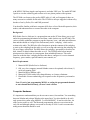
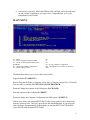
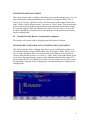
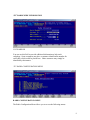
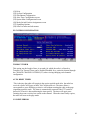
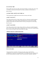
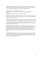
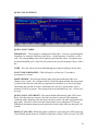
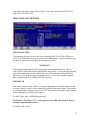
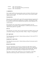
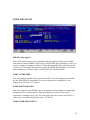
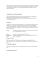
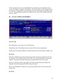
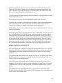
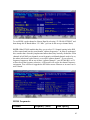
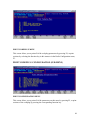
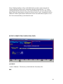
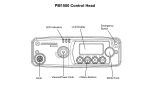
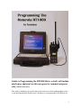
Guide to Programming the HT1000 (this is a draft, will include
much more material, work in progress for comment purposes
only) 2009-04-10 last edited
This guide is intended to be used by those who need to get a basic understanding of how
to use the Motorola RSS (Radio Service Software) to re-program their HT1000s for use
1
with MURS, 2M Ham (simplex and repeaters), and other VHF uses. The model HT1000
I prefer to own has a dtmf keypad to allow me to use phone patches with repeaters.
The HT1000 was chosen as the perfect SHTF radio, it’s old, well supported, there are
many accessories available for the radio. The HT1000 is mil-spec rugged as evidenced by
decades of use by Police, Fire and EMS personnel.
You should be familiar with basic computer skills, have a list of desired frequencies, their
modes, and understand how to connect the radio to the computer.
Background
RSS (Radio Service Software) is a program that runs on the PC that allows you to read
and write programming information to and from a radio (in this case, the HT1000). The
various sections within the program accept the frequency, tone, and other miscellaneous
data and then builds an “image of the flash memory into a “codeplug’ which can be
written to the radio. The RSS also offers functions to print the contents of the codeplug,
to retrieve the codeplug from the radio, as well as saving and retrieving the codeplug as a
file on a floppy or hard disk. The RSS allows the codeplug / personality to be stored on
disk, cloned, or edited without the radio as well. The HT1000 radio has an internal
microprocessor which runs its own program from embedded firmware. This radio
firmware reads the data / codeplug and uses this data to configure it’s receive/transmit
frequency, power modes, squelch controls, tone controls, etc.
Basic Requirements
1. Motorola RSS (Radio Service Software)
2. Old, very slow computer (around 100mhz seems to be optimal) with at least (1)
serial port running DOS.
3. Motorola RIB or RIBless cable
4. Motorola HT1000 with a fully charged battery or a battery eliminator
5. Ham Radio License authorizing you to operate on the frequencies you intend to
use.
Note: If you’re just programming MURS, or setting the programmed channels
to not transmit then obviously you won’t need a license
Computer Hardware
It’s important to understand that you do not want a newer, fast machine. You something
between 100mhz and perhaps 200mhz at the upper limit. You also should (to be safe)
only operate this system using MSDOS. I’ve tried MSDOS 7.10 and it works fine. An
older version works as well. The Motorola programming software was written in the
early 90s and although updates were made as recently as 1998 it’s safe to assume that
noting newer than that should be used.
2
Laptops vs. Desktops
I prefer to use a laptop with a good battery. I’ve had desktop systems die because the
UPS failed, commercial power failed and while the odds are certainly against it
happening while you just happen to be in the middle of writing a new codeplug into your
radio, it could happen. With a laptop I don’t have to worry about it. If you use a RIBless
connector and have secured it by screwing in the DB9 connector there is very little that
can interrupt your write operation. I also like using a laptop for when shtf and you may
not have commercial power but can keep a laptop charged. With the HT1000 since you
have only 16 channels, you may find yourself re-programming them often if you travel
outside of your normal area of operations.
Memory requirements are minimal. I’ve operated RSS in as little as 16mb of memory, so
I am sure whatever you have will do just fine.
Disk space requirements are also minimal. I have a Panasonic Toughbook with only a
4gb disk and to be honest that is about 3gb too much even with Windows 95 installed.
You should have at least a floppy drive in your machine so you can make backups of
your codeplugs and store them somewhere safe. It’s important to keep backups, you will
eventually need them if you do a lot of hacking on your radios.
Basic Procedure
1. Power up your computer, get into DOS. It is important that you are in DOS, not a
command window opened under Windows itself. You can either boot a DOS
floppy or restart Windows in DOS mode. For more discussion why this is
important please see Appendix A.
2. Make sure your HT1000 is turned off, then attach the RIBless cable to a serial
port (usually COM1) and then attach the cable to your HT1000. Power up the
radio at this time.
3
The RIBless connector should fit snugly, make sure it’s well secured.
3. Depending on where you installed the RSS you should change to that directory.
CD \MRSS\HT1000
HT1000
4. You should see the following “splash” screen.
4
5. Press “Enter” and proceed to the main menu.
6. Make a backup. If this is the first time you’ve programmed your HT1000 it’s a
very good idea to save it’s current configuration. You can do this by choosing
“F3” and then from the “Get-Save-Clone Menu” choose “F2” (Read Data from
Radio), then save the contents of it’s “codeplug” to disk by using “F7” (Save
Workspace Data to Archive File), the RSS will name the file based on the radio’s
serial number. It might be a very good idea to archive this within a zip file or
relocate it out of the RSS directory “ARC” which is the default location that RSS
uses to save/read codeplug data in order to preserve the “original” data.
7. Program the HT1000. Once you’ve made a backup copy of the codeplug, and you
wish to proceed to actually programming the radio, exit the “Get-Save-Clone”
menu by pressing “F10” and from the main menu, choose “F4” which is
“Change/View Radio Codeplug Data”. In the “Change/View Menu” you can reprogram every facet of your radio’s functionality. Once you’ve made the
necessary programming changes you should exit the “Change/View Menu” and
return to the “Get-Save-Clone” menu. Save the modified workspace data by
choosing “F7” (Save Workspace Data to Archive File) and using the <TAB> key,
select a new file name. Since you’re working in DOS, remember that the filename
can be 8 characters long with a 3 character file extension. An example of a valid
filename would be: terminus.001 Once you’ve saved the modified data, you are
now ready to write the new configuration to the radio. It is critical that this
process not be interrupted so make sure your radio battery is not low, and that the
RIBless cable is securely attached. Once you’re ready to proceed, press “F8”
(Program Data Into Radio). You will see a Red warning screen pop up prompting
you with a last reminder of what you’re about to do, and offering the option to
cancel or proceed. Press “F8” again and you will see a progress window pop up
indicating how far along the process is, and you should hear a “beep” at the
beginning of the process and a “beep” at the end. There should be no error
messages. If there were you probably just destroyed your radio.
5
8. Power down your radio, detach the RIBless cable, and then power the radio back
up and confirm it functions as you expect it to. Congratulations, you’ve just
programmed your HT1000!
MAIN MENU
F1 – HELP
F2 – Service: Alignment (Requires RIB)
F3 – Get/Save/Clone/Program Data From/to
Disk/Radio
F4 – Change/View Radio Codeplug Data
F5 – Print Codeplug Values
F6 –
F7 –
F8 –
F9 – Set Up Computer Configuration
F10 – EXIT Radio Service Software, Return to
DOS
The Main Menu allows you to access the screens which:
Align the Radio (F2 SERVICE)
Read or Program the Radio’s Codeplug, Get or Save a Codeplug Archive File, Clone data
from one radio to another (F3 GET/SAVE/CLONE/PROGRAM)
Examine/Change the contents of the Workspace (F4 CHANGE)
Print the contents of the Codeplug (F5 PRINT)
Examine/Change the Computer Configuration the RSS expects (F9 SETUP)
If there is an archive file named SETUP.MOT in the archive path, it will be loaded into
memory at start-up time. This file is provided on the distribution disk. If you desire any
other coeplug to be automatically loaded when you start the HT/JT1000/VISAR RSS,
resave that file with the name SETUP.MOT
6
F2 – Service: Alignment (Requires RIB)
SERVICE MENU SCREEN
F1 – HELP
F2 – Transmit Alignment
F3 – Receive Alignment
F4 – Signalling Alignment
F5 –
F6 – Test Mode
F7 – Controller Board Initialization
F8 –
F9 –
F10 – EXIT
This service screen allows you to access alignment parameters by navigating through
Transmit, Receive, and Signalling Alignment menus.
This service screen also allows you to test specific frequency, squelch, signalling, and
power level combinations in the Test Mode screen.
This service screen also allows you to initialize a replacement controller board with the
radio’s serial number as contained in the original factory-programmed controller board.
Transmit Alignment Menu
F2 – Reference Frequency Alignment
The software will read the radio’s codeplug when this function is selected.
REFERENCE FREQUENCY ALIGNMENT
This screen reads the codeplug and allows the Reference Oscillator Softpot to be set on
the right side of the screen. Use the <Up/Down Arrow> to increase/decrease the softpot
value in fine mode. Use the <Shift Up/Down Arrow> for coarse or “Turbo” mode. A bar
at the bottom of the screen shows the current setting in relation to the minimum and
maximum settings. F6 is used to toggle the PTT (key and dekey the radio) and F8 is used
to program the value into the codeplug/radio.
F3 – Transmit Power Alignment
The software will read the radio’s codeplug when this function is selected.
7
TRANSMIT POWER ALIGNMENT
This screen reads te radio’s codeplug, then allows you to set the transmit power. You can
select the frequency along with the power level (hi/low) by using the <Enter, Tab, or
Arrow> keys. Use the <Up/Down Arrow> to increase/decrease the softpot value in fine
mode. Use the <Shift/Up/Down Arrow> for coarse or “Turbo” mode. A bar at the bottom
go the screen shows the actual setting in relation to the minimum and maximum setting.
F6 is used to toggle the PTT (key and dekey the radio). Once the value is set correctly,
use the F8 function key (Program Value) to program the current transmit power setting
into the codeplug/radio.
F4 – Transmit Deviation Balance (Compensation) Alignment
The software will read the radio’s codeplug when this function is selected.
TRANSMIT DEVIATION BALANCE (COMPENSATION) ALIGNMENT
This screen reads the radio’s codeplug, then allows you to set the balance softpot. You
can selet the frequency along with the softpot value by using the <Enter, Tab, or Arrow>
keys. Use the <Up/Down Arrow> to increase/decrease the softpot value in fine mode.
Use the <Shift/Up/Down Arrow> for coarse or “Turbo” mode. A bar at the bottom go the
screen shows the actual setting in relation to the minimum and maximum setting. F6 is
used to toggle the PTT (key and dekey the radio). Once the value is set correctly, use the
F8 function key (Program Value) to program the current transmit power setting into the
codeplug/radio.
8
“F2” RADIO WIDE INFORMATION
CUSTOMER ID
You can use this field to provide additional information to help track
codeplugs. Some customers may have a customer identification number for
each radio, which could be placed here. Other customers may simply be
identified by their names.
“F3’ RADIO CONFIGURATION MENU
RADIO CONFIGURATION MENU
The Radio Configuration Menu allows you to access the following menus:
9
(F1) Help
(F2) System Configuration
(F3) Side Button Configuration
(F4) Alert Tone Configuration screen
(F5) Option·Mate Configuration Screen
(F6) Mode Switch Position Assignment screen
(F7) Signalling Options
(F8) Scan List menu and sub-menus
F2 SYSTEM CONFIGURATION
TIMEOUT TIMER
This option sets the length of time, in seconds, for which the radio is allowed to
Transmit. The Timeout Timer can be Enabled/Disabled for a particular channel through
the CHANGE CHANNEL OPTIONS (F2) when viewing/changing each channels’
configuration.
AUTO RESET TIMER
This is the time the radio will remain in the carrier squelch mode after the radio has
received a Quik-Call II page or MDC Sel-Call directed to it. The timer allows a
conversation to occur following a selective call without resetting the radio to the page
(signalling squelch) mode. The timer is automatically restarted if the PTT switch is
pressed or if carrier is detected during the timer period. The timer will again start
counting down once activity has ceased on the channel. When the timer finally expires,
the radio will reset to the page mode.
CS SLEEP PERIOD
10
This field specifies the "sleep period" for a radio on a Carrier Squelch channel when the
Battery Saver feature is active. During the sleep period, the radio powers down the
receiver and synthesizer and does not check for activity. After the sleep period, the radio
turns back on and is maintained in the ON state for a period of time sufficient to detect
carrier. If an on-channel carrier is detected, the receiver will be maintained in the ON
state and the radio will unmute until carrier disappears. When carrier disappears, the
10-second inactivity timer will be started. When this timer expires, the radio will
resume battery saving activity by periodically entering sleep mode for the specified
period. As the sleep period is increased, battery life will increase, but the amount of
speech that can be missed at the beginning of a call will also increase.
PL SLEEP PERIOD
This field specifies the "sleep period" for a radio on a PL channel when the Battery Saver
feature is active. During the sleep period, the radio will power down the receiver and
synthesizer and does not check for activity. After the sleep period, the radio turns back
ON and is maintained in the ON state for a period of time sufficient to detect carrier. If
an ON channel carrier is detected, the receiver will be maintained in the ON state for a
period of time sufficient to detect PL. If no valid PL is detected, the radio goes back to
the sleep mode immediately. If a valid PL is detected, the radio will unmute until the
channel unmuting conditions are no longer met. When carrier disappears, the 10-second
inactivity timer will be started. When this timer expires, the radio will resume battery
saving activity by periodically entering sleep mode for the specified period. As the sleep
period is increased, battery life will increase, but the amount of speech that can be missed
at the beginning of a call will also increase.
AGC
This field enables/disables the use of the radio microphone AGC circuitry. AGC has the
ability to level out the variations in audio volume due to a radio user speaking too softly,
too loudly, or holding the radio too far from his mouth. All messages will be heard at the
receiving end at a more pleasant volume level than if AGC was not used. When using
AGC, your voice must be louder than the surrounding ambient noise so that your voice is
in control of the volume level. AGC is available on VISAR, JT1000, and HT1000 "B"
and later models only.
CLEAR CHANNEL DEFINITION
Defines the condition for a clear channel before PTT or RAT transmission is permitted in
conjunction with the Transmit Inhibit on Busy Channel option in the Channel
Configuration Menu.
Matched PL - Clear channel is defined as an absence of carrier or a carrier with a
Matched PL. The user will be inhibited from transmitting if activity is detected on the
channel with a PL code other than his/her own, or with no PL.
11
No Carrier - Clear channel is defined as an absence of carrier only. The user will be
inhibited from transmitting if any activity is detected on the channel.
TRANSMIT LED
This option, when enabled, will turn on the red LED when the radio is in the transmit
mode.
FLASHING LED
This option controls the function of the flashing LED. It can be set to indicate: low
battery, busy channel or both.
QUICK KEY OVERRIDE
This option enables/disables the PTT quick-key operation mode. If two PTT activations
occur within one second of each other, this overrides the transmit inhibit option, allowing
the radio to transmit over the "Channel Busy" condition.
TX INHIBIT MONITOR FUNCTION
This option enables/disables the normal monitoring of channels where transmit inhibit on
busy channel is enabled.
BATTERY SAVER PL LOCKOUT
When Battery Saver PL Lockout is enabled, PL will NOT be decoded when the radio
periodically comes out of sleep mode until carrier drops. Therefore, a radio which enters
sleep mode while a carrier is on the channel with wrong PL or no PL will not unmute to
another call until carrier drops. This method of operation (not decoding PL) significantly
increases battery savings, but can cause problems in some systems. Use of Battery Saver
should be carefully tested in the customer system when this option is enabled.
SIDE BUTTON CONFIGURATION
12
VISAR, HT1000 "B" and later, and JT1000 MODEL SIDEBUTTON FUNCTIONS
(Applicable to Sidebutton 1,2,3 selections.) See Figure 2 for details.
Use the UP/DOWN arrow keys to select the function for this button. Not all functions
are available on all models. The possible functions are as follows: (When "Applicable all
models" seen, function is also in HT1000 "A" models)
NOTE: The RSS will not allow sidebutton functions to be duplicated on more than one
button, or duplicate a function that is assigned to another control. Example: Scan on a
sidebutton and channel-slaved autoscan in the same radio. If Scan is already assigned to
another control, scan-related selections will not be displayed among the choices.
Monitor - Radio will unsquelch when this button is pressed, allowing you to listen to
activity on the channel. Applicable all models.
Blank - No function. No key chirp is sounded. Applicable on VISAR, HT1000 "B" and
later, and JT1000 models.
Scan Programming Status Scroll - Allows the operator to select a channel's status in the
scan list (Not in List, Non-priority, Priority) by scrolling through the three states as this
button is pressed. The status of the channel is indicated by the bicolor LED. LED OFF
indicates not in scan list. LED Green indicates Non-priority status. LED Red indicates
Priority status. Applicable VISAR, HT1000 "B" and later, and JT1000 models.
Monitor/Scan Programming Status Scroll - Combines the Monitor function with
Scan Programming Status Scroll while in Scan Programming mode. Applicable VISAR,
HT1000 "B" and later, and JT1000 models.
Emergency Alarm - An MDC or GEStar Emergency Alarm sequence is initiated
when this button is pressed. Applicable VISAR models only. HT1000 models always
have Emergency on the Orange button. JT1000 models always have DTMF mode on the
Orange button
13
Phone Encode - Places the radio in the Telephone Encode mode, initiating an autoaccess sequence if so programmed. Applicable for VISAR keypad models only. JT1000
phone encode is always assigned to the top (orange) button.
Select Button - Allows temporary removal of a channel from the scan list in the Nuisance
Delete Function, and performs the Scan Programming Status Scroll function in the Scan
Programming mode. Applicable all models.
Scan/Scan Programming On/Off - A short press will toggle the Channel Scanning mode
on or off. A long press will place the radio in the Scan Programming mode, where the
scan list can be modified by the radio operator. Note that in Scan Programming mode, the
radio will not unmute to an channel traffic. A tone will sound to remind the operator if
the radio has been left in the Scan Programming mode with no key activity for more than
20 seconds. To complete the Operator Selectable scan functionality, the other sidebutton
must be assigned to the Scan Programming Status Scroll function. See below for scanrelated button setups. Applicable VISAR, HT1000 "B" and later, and JT1000 models.
Singletone Encode #1 and #2 - Initiates transmission of the selected Singletone.
Applicable VISAR, HT1000 "B" and later, and JT1000 models.
Scan On/Off - Allows scan to be toggled on and off. No scan programming is allowed
with this setup. Applicable VISAR, HT1000 "B" and later, and JT1000 models.
Light Button - Allows toggling of the display/keypad backlighting on and off. Applicable
to models with display and/or keypad.
RAT - An MDC Repeater Access Code is transmitted when this button is pressed.
Applicable to Visar and HT1000 radios.
MSPL Select - This function allows the user entry/exit to the Multiple Selectable PL/DPL
entry mode in JT1000 models only. This function allows the user to substitute the
Squelch coding on one channel to another channel
Possible sidebutton setups for scanning (VISAR, HT1000 "B" and later, and JT1000
models only. Sidebutton nomenclature below refers to VISAR):
Operator Selectable Scan only
Sidebutton 1 = Scan/Scan Programming On/Off
Sidebutton 2 = Scan Programming Status Scroll
Operator Selectable Scan with Monitor
Sidebutton 1 = Scan/Scan Programming On/Off
Sidebutton 2 = Monitor/Scan Programming Status Scroll
Operator Selectable Scan with Nuisance Delete
14
Sidebutton 1 = Scan/Scan Programming On/Off
Sidebutton 2 = Select
Scan On/Off only
Sidebutton 1 = Scan On/Off
Sidebutton 2 = Any other function
Scan On/Off with Nuisance Delete
Sidebutton 1 = Scan On/Off
Sidebutton 2 = Select
MONITOR LONG PRESS PERIOD
A long press involves pressing and holding a button for an extended period of time to
enable a secondary radio function or feature. This means that the user must press and
hold the monitor button down for the time specified by this field to enter Permanent
Monitor mode.
PERMANENT MONITOR
If this option is enabled, the radio will enable the Permanent Monitor feature. To enter
Permanent monitor, you hold down on the monitor button for the time specified in the
Monitor Long Press Period field. Permanent Monitor operates as defined in the
Permanent Monitor Definition field. The Permanent Monitor state is not preserved across
channel changes or power cycling.
PERMANENT MONITOR DEFINITION
This field specifies the squelch mode that the radio will be in during a momentary press
of the Monitor button or in Permanent Monitor Mode. Open Squelch implies that the
radio is continuously unmuted, and PL Defeat implies that the radio is in Carrier Squelch
during Monitor. This definition does not apply to Monitor during Scan mode. Monitor
operation during Scan is controlled by the PL Defeat field on the Scan Configuration
screen.
MAN DOWN
This option Enables/Disables the capability to initiate the transmitting of an emergency
alarm sequence (including the ID code) when the radio is tipped more than 60 degrees
from its vertical axis. Emergency must be enabled for this feature to work. NOTE: THIS
FEATURE REQUIRES A SPECIAL ATTACHMENT.
15
Figure 3. Mode Switch A,B,C and Side Buttons 1, 2, 3
ALERT TONE CONFIGURATION
16
MASTER ALERT TONE CONTROL
This field allows disabling of all alert tones controlled from this and all other screens,
with 2 exceptions. These are tones which cannot be disabled from the RSS. They are:
MDC Select Call Alert
QC-II Select Call Alert
If the Master Alert Tone Control is set to "Disabled", then none of the Alert Tones will be
allowed to be enabled individually until the Master Alert Tone Control is enabled.
IMPORTANT NOTE:
There are two actions that will override and reset the state of "Master Alert Tone
Control". These are:
1. Use of the F9 DEFAULT key on any screen that has alert fields.
2. Changing the "Signaling Type" field on the CHANGE:RADIO:SIG: screen
(MDC/STAR/ATIS Options), which sets the new signal type defaults.
If it is desired to disable all of the alert tones, only the Master Alert Tone Control need
be changed. All individual tones will be disabled.
When the Master Alert Tone Control is re-enabled, all individual tones will still be
disabled, so the desired tones must be turned on individually.
POWER UP ALERT TONE
This option Enables/Disables the Power Up Alert Tone which, when enabled, beeps if the
radio's software self-check indicates a good radio.
ILLEGAL CHANNEL ALERT
17
When an un-programmed channel is selected, an alert tone will be emitted to warn the
user that it is illegal and not available.
TIMEOUT TIMER ALERT
This option enables/disables the transmit timeout timer alert. This alert tone is sounded
from the time the transmit timeout timer expires until the PTT button is released.
TIMEOUT TIMER PRE-ALERT
This option enables/disables the timeout timer pre-alert, which will be heard for four
seconds before the timer times out.
PL DEFEAT
When this option is enabled, the radio will generate an alert tone before it enters the PL
Defeat mode. The radio enters the Permanent PL Defeat mode when the monitor is held
down for the Monitor Long Press Period.
SCAN PROGRAMMING ALERT
This Enables/Disables an alert tone when entering or exiting from the scan programming
mode.
PRIORITY CHANNEL LOCK
When the radio is in priority scan mode and locks onto activity on the priority channel, an
alert tone is generated if this field is enabled.
PTT TX INHIBIT ALERT
This field enables an alert to be generated if the PTT button is pressed while the radio is
in a state where transmission is inhibited (e.g. Rx only channel, busy channel, etc.).
MAN DOWN PRE-ALERT TONE
This option Enables/Disables the generation of an audible tone prior to the initiation of
the emergency sequence. This tone is used to remind the user that the emergency
sequence is about to start.
TX LOW BATTERY
When enabled, this alert tone will be generated on dekey only when a low battery
condition is detected while in TX mode.
18
RX LOW BATTERY
When enabled, this alert tone will be generated periodically according to the value of the
Low Battery Alert Interval field when a low battery condition is detected while in
Receive mode.
LOW BATTERY ALERT TONE INTERVAL
This determines the length of time between the low battery alert chirps.
ALERT VOLUME TX
This field specifies the fixed volume setting used for any Alert tone sounded during the
Transmit mode. If this volume setting is programmed to 00, all Alert tones sounded
during Transmit mode will default to the last volume pot setting that was read during
Receive mode.
ALERT VOLUME RX
This field specifies the fixed volume setting used for any Alert tone sounded during the
Receive mode. If this volume setting is programmed to 00, all Alert tones sounded during
Receive mode will default to the current volume pot setting.
OPTION-MATE CONFIGURATION
PLUG-IN BOARD
Setting this field to "Installed" will change the audio routing in the HT1000 to
accommodate an audio-processing option board. It will change the audio routing path for
BOTH Transmit and Receive audio. DO NOT set this field to "Installed" without an
19
option board installed in the radio. If this field is set to "Installed" without an option
board in place, the radio Transmit and Receive audio will be muted. Audio-processing
option boards can ONLY be used in HT1000 "C" or later model radios or HT1000 "B"
and "A" model radios that have been upgraded with the Option·Mate Interface Plug
controller board.
RSS Cloning IS allowed even if Option·Mate settings are different. The setting in the
source radio is copied to the target, and a warning is given. See the screen HELP for the
Get/Save/Clone Screen for cloning tips.
If the Option·Mate Plug-In Board fields are set to different values, then it will NOT be
possible to clone radios through the direct radio-to-radio cloning process. This is intended
to prevent the audio routing information from an Option·Mate-enabled radio from being
cloned to an Option·Mate-disabled radio which would render the target radio inoperative.
It will also prevent an Option·Mate-disabled radio from being cloned to an Option·Mateenabled which would render the target radio plug-in board inoperative.
For example, if an HT1000 "C" model is radio-to-radio cloned to a "B" or earlier model,
the Plug-in Board field in the "C" model must be set to "Not Installed", or the cloning
will not be allowed. Radio-to-radio cloning where an HT1000 "A" model is the source
radio is an exception - if an "A" model HT1000 is radio-to-radio cloned to an HT1000
"C" model which has the Option·Mate Plug-In Board field set to "Installed", the audio
routing information will be lost and must be reprogrammed.
MODE-SWITCH POSITION ASSIGNMENT
RADIO MODE SWITCH SCREEN
The three-position toggle switch (also referred to as the Radio Mode Switch) on top of
the HT/JT1000 can have two functions assigned to each of its positions. This switch
screen allows the user to select the desired combination of functions. See Figure 3 for
details.
20
In the table at the bottom of the screen, the columns marked Position A, B, and C,
correspond to the physical positions of the switch. The rows marked Function 1 and 2
correspond to the functions assigned to those positions.
As you navigate through the different function combinations at the top of the screen
(using <Enter>, <Tab>, or the Arrow keys) you will notice the assigned functions
changing. The selection which is highlighted when the screen is entered for the first time
is the one which IS CURRENTLY PROGRAMMED into the radio. The selection which
is highlighted when the screen is exited is the one which WILL BE PROGRAMMED
into the radio. The different switch selections are explained below.
Note: The RSS will not allow a toggle switch setup that duplicates functions already
assigned to other controls. Example: Scan on the toggle switch and channel-slaved autoscan in the same radio. If scan is already assigned to another control, it will not be
possible to navigate to scan-related selections on this screen. Please note also that on
800 MHz models, no selection will be allowed which involves the selection of a power
level other than the standard high power level, which is factory adjusted to 3 Watts for
800 MHz. Selections disallowed are Hi/Low Power, Hi/Low Power & Scan, PAC·RT,
and PAC·RT & Scan.
Scan/Scan Programming 1 - POSITION A turns Scan Programming ON. Note that the
radio is NOT listening to the channel when in Scan Programming Mode. Channels can
be added to the scan list, deleted from the scan list, and the Priority Channel changed,
but the Scan Type CANNOT be changed in Scan Programming. POSITION B turns both
Scan Programming and Scan OFF. POSITION C turns Scan ON.
Scan/Scan Programming 2 - Same as above except POSITIONS A and C exchange
functions. Having Scan Programming on POSITION C is a little safer, since it is more
difficult to accidentally knock the switch into the Scan Programming position with this
setup.
Scan/Talkaround - POSITION A is Direct Mode (Talkaround) with Scan OFF.
POSITION B is Repeat Mode with Scan OFF. POSITION C is Repeat Mode with Scan
ON.
Scan/Squelch Defeat - POSITION A defers to the Squelch Option selected on the
Channel Screen for this channel. Scan is OFF. POSITION B forces Carrier Squelch
receive. Scan is OFF. POSITION C turns Scan ON. Squelch operation in Scan is
determined on the Scan Configuration Screen.
Scan/PAC·RT - POSITION A is the PAC·RT position. It forces PL Transmit at Low
Power. Scan is OFF. PAC·RT is used with vehicular or portable repeaters to boost
power or to cross bands. POSITION B disables PL on Transmit. Scan is OFF.
POSITION C disables PL on Transmit. Scan is ON.
21
Talkaround - POSITION A is the Direct position, where two radios communicate
without the benefit of the repeater, both transmitting and receiving on the programmed
receive frequency. POSITIONS B and C operate in the Repeat mode.
Squelch Defeat - this is the default switch setting.
POSITION A defers to the squelch selected on the Channel Configuration
Screen.
POSITIONS B and C both force Carrier Squelch operation.
PAC·RT - POSITION A is the PAC·RT position. It forces PL Transmit at Low Power.
PAC·RT is used with vehicular repeaters to boost power or to cross bands. POSITIONS
B and C disable PL on Transmit.
Hi & Low Pwr - POSITION A forces High power operation regardless of the setting on
the Channel Configuration Screen. POSITION B forces Low power operation regardless
of the setting on the Channel Configuration Screen. POSITION C forces Low power
operation regardless of the setting on the Channel Configuration Screen. This setting is
NOT allowed for JT1000 models.
Hi & Low Pwr/Scan - POSITION A forces High power operation regardless of the
setting on the Channel Configuration Screen. Scan is OFF. POSITION B forces Low
power operation regardless of the setting on the Channel Configuration Screen. Scan is
OFF. POSITION C forces Low power operation regardless of the setting on the
Channel Configuration Screen. Scan is ON. This setting is NOT allowed for JT1000
models.
Talkaround/PL - POSITION A defers to the Squelch Option selected on the Channel
Screen for this channel. Radio operates in Repeat mode. POSITION B forces Carrier
Squelch receive. Radio operates in Repeat mode. POSITION C forces Carrier Squelch
receive. Radio operates in Direct mode.
22
Figure 5
SIGNALING OPTIONS MENU
SIGNALLING OPTIONS MENU
The Signalling Options Menu allows you to access the following subscreens by pressing the corresponding function key:
Quik-Call II Options
MDC/GEStar/ATIS Options
Singletone
DTMF
- (F2)
- (F3) Not present for JT1000 models.
- (F4)
- (F5)
23
QUIK-CALL II OPTIONS
QUIK CALL II TABLE
FREQUENCY - The Frequency is displayed in Hertz (Hz). You may scroll through the
frequencies by using the Up/Down Arrow Keys. As the frequency is scrolled, so is the
code. The corresponding code will be displayed, provided one exists. Frequencies may
be entered manually up to 3100.0 Hz, but codes do not exist for frequencies above 2468.2
Hz.
CODE - The code values may be scrolled through by using the Up/Down Arrow Keys.
LONG TONE B DURATION - This field may be set from 0 to 33 seconds in
increments of 1 second.
SLEEP PERIOD - This field specifies the radio sleep period when the radio is in
"Battery Saver" mode. For a channel with QC-II decode option enabled, the sleep period
is related to the first tone, and must be programmed so that there is no loss of any page.
The default sleep period of 60 ms is calculated to be safe for a system with a Tone A
duration of 500 ms or greater. The sleep period can be adjusted from 5 ms - 1050 ms in 5
ms steps.
QUIK CALL II AUTO RESET - This option Enables/Disables the Quik Call II Auto
Reset. After the alert tone sequence, the auto-reset timer is started. If the unmuting
conditions of the channel are not met before the timer expires, the radio will return to the
page mode. The timer will be reset and restarted upon every subsequent PTT release.
If disabled, the monitor button must be pressed to reset the radio back into the Quik Call
II mode.
SELECT CALL LED - When this option is enabled, it causes the green LED on the top
of an HT1000 and the front of a VISAR to flash when a Select Call is received. The LED
24
will flash for the entire length of the message. This field controls the LED for QC II,
MDC and ATIS Select Call.
MDC/STAR/ATIS OPTIONS
SIGNALLING TYPE
The signaling type may be set to one of the following: MDC1200, STAR (GEStar), or
ATIS. Use the up/down arrow keys to select the signaling type. Once the signaling type
has been set, the screen will display the appropriate options.
WARNING!!!
Selecting other signaling types from the original one programmed into the radio or
archive WILL destroy the current signaling data in the screen. Cycling through signaling
types and returning back to the original type does NOT imply that the original data is
preserved. If you cycle through the signaling types, recovery of the original signaling
data is possible only by re-reading the radio or archive.
PRIMARY ID
Each radio within a system will have a unique 4 digit number associated with it referred
to as the Primary ID, and is used to identify the portable at the base station. This number
is transmitted upon a change in state of the PTT. The Primary ID number range depends
on the Signaling Type being used as follows:
For MDC1200: 0001 to DEEE (hexadecimal),
WARNING: The entry of "F's" in any position of an MDC1200 Primary ID may
introduce unpredictable behavior.
For STAR (400 or 800):
25
Portable:
Extended:
0001 - 2047 (decimal) or
0001 - 8191 (decimal) (with a special decoder)
0001 - 9999 (decimal).
VARIABLE ID
The Variable Unit ID is used to group radios so that several radios will decode the same
Selective Call or Call Alert. The Variable Unit ID consists of a three digit hex number
ranging from 000 to EEE.
TRANSMIT PL
When this option is Enabled, the PL signal will be transmitted during the transmission of
RAT, Emergency, or auto-acknowledgement on a PL channel. Encoding of PL during
the transmission of PTT ID is not controlled by this field but is always enabled on a PL
encoded channel.
When Disabled, the PL signal will not be transmitted during MDC nor STAR
Transmissions, except for the PTT ID transmission. A valid PL must be selected on the
channel for this option to be applicable.
PTT ID
This field allows you to choose when your radio transmits its ID number relative to when
you transmit a message. You may select "None", "Dekey", "Keyup", or "Keyup/Dekey".
PTT SIDE TONE
This field enables the generation of a sidetone during encoding of a "Stat-Alert PTT ID"
and a STAR PTT ID.
EMERGENCY SIDE TONE
This field enables the generation of a sidetone during encoding of an emergency packet
transmission.
REMOTE MONITOR
This field, when Enabled, will activate the decoding for the MDC Remote Monitor
command. The Remote Monitor command will cause the radio to key up and transmit
ambient audio for a period of time that is controlled via the command itself. The time
period will be 20 seconds multiplied by the "multiplier field" in the command.
This feature is limited to radios with firmware version 2.06 and later. If this field is
enabled on a radio having an earlier version firmware, it will have no effect.
26
RADIO CHECK
When this option is enabled, the dispatcher is allowed to check the state of the radio
(turned on or off), as long as the radio is in range of the system.
MDC Auto Reset
This option enables the auto reset timer for the MDC Selective Call signaling.
STICKY REVERT
This field, when enabled, will cause the radio to operate in the Sticky Channel Revert
mode when in MDC Emergency. Sticky Revert is characterized by the radio remaining
permanently on the revert channel after the MDC Emergency message has been
transmitted and acknowledged. The radio must be powered off and on to return to normal
channel control. Please note that the MDC/STAR/ATIS Decode field on the Channel
Configuration Screen must be set to "Enabled" in order for the radio to be able to decode
the Emergency ACK that is generated from the MDC fixed equipment. This feature only
needs to be enabled on the Emergency Revert channel when Emergency Revert or Sticky
Revert is in use. This feature is limited to radios with firmware version 2.06 and later. If
this field is enabled on a radio having an earlier version firmware, it will have no effect.
STICKY REVERT ALERT
This field enables an alert tone to be generated if PTT is pressed when the radio is on the
Sticky Revert Channel. It reminds the user that the radio is transmitting on the channel
different than the one indicated by the Channel Selector knob. On VISAR models, the
display will correctly indicate the Sticky Revert Channel.
This feature is limited to radios with firmware version 2.06 and later. If this field is
enabled on a radio having an earlier version firmware, it will have no effect.
CALL ALERT
This per-radio feature provides a convenient way for the dispatcher to page a radio user.
When a Call Alert (page) is received, the radio emits a continuous series of four beeps
and the LED flashes green. The alert continues until you acknowledge it by pressing the
PTT button or press and release the monitor button.
CALL ALERT LED
When this option is enabled, it causes the green LED on the top of an HT1000 and the
front of a VISAR to flash when a Call Alert is received. The LED will flash until the alert
tones terminate. This field controls the LED for QC II, MDC, and ATIS Call Alert.
27
SELECT CALL LED
When this option is enabled, it causes the green LED on the top of an HT1000 and the
front of a VISAR to flash when a Select Call is received. The LED will flash for the
entire length of the message. This field controls the LED for QC II, MDC and ATIS
Select Call.
REPEATER ACK ALERT
This alert sounds when the acknowledgement to Manual Repeater Access is received.
EMERGENCY
This field when enabled, allows the following emergency options to be enabled/disabled:
Emergency Tx Light, Emergency Alert, Emergency Ack Alert, Silent Emergency, Silent
Emergency with Voice, Channel Revert, and Priority Revert Channel.
NOTE: Emergency messages are always transmitted at HIGH power, overriding any
power select feature, whether programmed or switch operated.
Also note that the MDC/STAR/ATIS Decode field on the Channel Configuration Screen
must be set to "Enabled" in order for the radio to be able to decode the Emergency ACK
that is generated from the MDC fixed equipment. This feature only needs to be enabled
on the Emergency channel, or if used, the Emergency Revert channel.
SINGLETONE CONFIGURATION
FREQUENCY
28
The two frequency fields specify the tone frequencies for Singletone #1 and Singletone
#2. The frequencies can range from 299 to 3011 Hz. When a frequency is entered or
scrolled and the screen exited, the value may change by a few Hz when you return to the
Singletone screen. This is because the frequency is encoded and then decoded when the
screen is exited and then re-entered. The frequency displayed is the nearest encodable
frequency to the frequency entered, and will not differ from the frequency entered by
more than 0.5% except at the upper end of the frequency range, where it may vary as
much as 1.0% These are the only fields which apply individually to the two Singletones.
SINGLETONE DURATION
This field specifies the timed duration of the transmitted Singletone. The time can vary
from 132 ms to 33 seconds in increments of 132 ms.
SINGLETONE TX PRETIME
This is the period preceding the transmission of the Singletone during which silent carrier
or carrier with PL (if on a PL channel) is transmitted. This time can range from 0 to 6.375
seconds.
SINGLETONE SIDETONE
This field enables/disables sidetone feedback during Singletone encode. The sidetone is a
900 Hz tone which lasts for the duration of the transmitted Singletone. This sidetone
applies to Singletone encode via PTT only.
SIDEBUTTON ACCEPT TONE
This field enables/disables the "Accept tone" that is generated as feedback to the user
when Singletone is encoded via a sidebutton. The accept tone is a 900 Hz, 75 ms tone.
NOTE: In order for Singletones to operate properly, they must be enabled per channel on
the CHNAGE/CHANNEL:OPTIONS Screen. If Singletone on a sidebutton is desired,
the sidebutton must be assigned on the CHANGE/RADIO:SIDEBUTTON screen.
29
DTMF PHONE LIST
PHONE #1 through #8
These fields allows storage of pre-programmed phone numbers which can be recalled
from memory and auto-dialed. Legal values are any DTMF digit (0 through 9, # and *) or
a pause. A pause is created by entering "P" from the keyboard, and is represented on the
screen by a P. The length of the pause is equal to the DTMF Digit Duration. Pre-stored
phone numbers are a feature ONLY of the HT1000 "B" and later models.
DTMF TX PRE-TIME
This is the time period that carrier or carrier with PL (if on a PL channel) is sent before
the first DTMF digit is transmitted. The value is expressed as a multiple of 25 ms,
ranging from 25 ms to 6.375 seconds.
DTMF DIGIT DURATION
This is the actual time that DTMF tones are transmitted on the channel for a single digit
during auto-dial, or manual dial if a timed tone duration is selected. The value is
expressed as a multiple of 4.12 mS. The value ranges from 4.12 mS to 1050.60 mS. A
value of zero is not allowed. Default value = 152.44 mS.
DTMF INTER-DIGIT DELAY
30
This is the time period that carrier or carrier with PL (if on a PL channel) will be
transmitted between DTMF digit during autodial. The value is expressed as a multiple of
4.12 ms, ranging from 4.12 ms to 1050.60 ms. A value of zero is not allowed.
DTMF ACCESS CODE
This is the code used to access the fixed end telephone interconnect equipment. Some
conventional interconnect systems require a * to access the telephone line. Other systems
require a multi-digit access code which consists of 1 to 4 digits and may or may not
contain a *. Multi-digit access-codes are used to prevent unauthorized access to the
telephone interconnect system.
DTMF DE-ACCESS CODE
This field specifies the DTMF de-access code that causes the telephone interconnect
equipment to release the phone connection. It may contain any legal DTMF digit. Release
codes are used to improve system loading by eliminating dead air time after interconnect
calls are completed.
F2 DTMF CONFIG (SUB-MENU)
ACCESS/DE-ACCESS TYPE
This field specifies whether Telephone Interconnect access is automatic or manual. If set
to automatic, the radio will auto- matically send the pre-programmed access code upon
depression of the Phone button, and will automatically send the de-access code when the
Phone button is pressed to hang up. If set to manual, the access/de-access codes must be
keyed in manually.
DTMF TONE TYPE
31
This field determines whether the DTMF tones transmitted are "Continuous" (transmitted
as long as the key is held down) or "Timed" (transmitted for the length of time specified
by the DTMF Digit Duration field on the CHANGE:RADIO:SIG:DTMF screen) in a
Manual dial situation.
USER PHONE LIST PROGRAMMING
This field enables/disables the user's ability to modify entries in the pre-programmed
phone number list from the keypad (Phone #1 through #8 on the
CHANGE:RADIO:SIG:DTMF screen). This feature is only available on HT1000 "B"
revision and later models.
DTMF ANI
DTMF ANI (Automatic Number Identification) is a PTT-ID function implemented with
DTMF tones. It is available by channel (PTT-ID field on the CHANGE:CHANNEL
screen must be enabled), but cannot be mixed with any other type of PTT-ID function
(MDC1200, STAR PTT-ID, or Singletone on PTT) on separate channels. The values this
field can assume are:
Keyup
ANI code transmitted when PTT is pressed. User must wait until ANI
code is transmitted before speaking.
Dekey
Keyup/Dekey
None
ANI code is transmitted when PTT is released.
ANI code is transmitted upon PTT press and again upon PTT release.
DTMF ANI disabled.
DTMF ANI CODE
This field specifies the DTMF digits that will be transmitted when DTMF ANI is
Selected. The code can be a maximum of 8 DTMF digits. Any DTMF digit can be used
(0-9, *, #).
DTMF PRE-EMPHASIS
This field enables/disables the use of the pre-emphasis circuitry for the encoded DTMF
tones.
DTMF SIDETONE TYPE
32
This field selects the type of sidetone to be used during DTMF digit encode. The type of
sidetone is also dependent on the "DTMF Tone Type" field, and the type of dialing used
(manual or automatic). This following summarizes the type of sidetone which can be
expected.
DTMF Sidetone
Type
DTMF Tone Type
Sidetone for
Manual Dial
Sidetone for Autodial
900 Hz
DTMF Tones
900 Hz
DTMF Tones
Continuous
Continuous
Timed
Timed
900 Hz
900 Hz
DTMF Tone
DTMF Tone
900 Hz
900 Hz
This combination is not supported
DTMF HOT KEYPAD
This field, when enabled, will allow DTMF digit transmission without use of a
sidebutton dedicated to the phone function. When this field is enabled, the user only
needs to press and hold the PTT button, and then press the desired keys on the keypad to
transmit the corresponding DTMF digits. Some of the features of the dedicated Phone
mode will not be available when this method is used, however. Automatic transmission
of Access/Deaccess codes will not be possible, and the VISAR display will not show
"PH" to indicate Phone mode.
This feature is limited to radios with firmware version 2.06 and later.
If this field is enabled on a radio having an earlier version firmware, it
will have no effect.
F8 – SCAN LIST CHANNELS
SCAN LIST CHANNELS
33
Use the up/down arrow key to enable/disable for scanning any of the channels on the
screen. If a channel is marked as "disabled" it will not be scanned. Only channels which
are marked as "Programmed" on the Channel Screen for that channel can be added to the
scan list. If unprogrammed channels are added to the list, they will be disabled when the
screen is exited.
F2 – SCAN CONFIG (SUB-MENU)
SCAN TYPE
This field allows you to select one of the following:
Non-Priority Scan: The channels in the scan list will be scanned continuously.
Priority Scan: The priority channel is checked in between each non-priority channel scan.
PL SCAN
When set to Enabled, the scanner will only stop on the non-priority channels in the scan
list which are coded with the proper PL or DPL as set up in the Channel screen for that
channel. The scanner will stop on the priority channel with carrier activity only.
When set to Priority Channel, the scanner will stop on both non-priority and priority
channels only when the proper PL/DPL coding is detected.
When set to Disabled, the scanner will stop on any channel in the scan list with carrier
activity only.
PL SCAN
34
When set to Enabled, the scanner will only stop on the non-priority channels in the scan
list which are coded with the proper PL or DPL as set up in the Channel screen for that
channel. The scanner will stop on the priority channel with carrier activity only.
When set to Priority Channel, the scanner will stop on both non-priority and priority
channels only when the proper PL/DPL coding is detected.
When set to Disabled, the scanner will stop on any channel in the scan list with carrier
activity only.
Thought should be given to whether the use of the Selectable Channel Unmute feature
(also on the Scan Configuration screen) would be more appropriate for a given situation.
Selectable Channel Unmute is less restrictive and will cause the radio to unmute to more
traffic than Priority Channel Unmute.
PRIORITY CHANNEL DEFINITION
This feature enables the priority channel to follow the selected channel or be designated
as a specific fixed channel.
DESIGNATED TX CHANNEL
When this option is enabled, if the PTT or monitor is pressed any time during scan,
transmission or monitoring will occur on the designated channel. The valid range of
channels is 1 to the maximum channel allowed in the radio. Only channels which are
marked as "Programmed" in the Channel screen (CHANGE:CHANNEL) will be
displayed as possible selections. If used in conjunction with TALKBACK SCAN, the
talkback feature has priority. That is, if there is an active channel for talkback purposes,
that channel will be used; if not, then the designated transmit channel is used.
TALKBACK SCAN
This option enables the radio talkback scan feature. If PTT or monitor is pressed at any
time during scan, transmission or monitoring will occur on the preassigned channel.
Preassigned channel is and depends on radio status as follows:
A. On an active channel if the scanner is locked onto it.
B. On the last active channel if the Rx Hang Time is in effect.
C. On the last channel of transmission if the Tx Hang Time is in effect.
D. If no activity exists, transmission will occur on the current selected mode.
ACTIVE CHANNEL TONE
This field, when enabled, will allow the Active Channel Tone to be generated. This tone
indicates to the user which was the last channel that carried traffic that the radio unmuted
35
to. When the Channel Selector is cycled through the available channels, the tone will be
sounded when the last active channel is accessed.
This feature is limited to radios with firmware version 2.06 and later. If this field is
enabled on a radio having an earlier version firmware, it will have no effect.
SCAN CHANNEL LOCKOUT
This option, when enabled, causes the radio to lock out of the scan list any channel where
the carrier being received is right but has the incorrect PL number or no PL number.
When the carrier has dropped, scanning for that channel is resumed.
PL DEFEAT
When this option is enabled, holding the monitor for the preset amount of time during
scan will place the radio in the permanent monitor mode (PL decode defeated). The state
of the permanent monitor mode always defaults to carrier squelch, and is independent
from the noise squelch setting in the Side Button Configuration Menu. This option is
only valid when the radio is in the channel scanning mode. For operation of PL defeat
during non-scan mode, refer to the Side Button Configuration Menu.
NUISANCE DELETE
When enabled, this option allows the user to temporarily delete a busy channel from the
scan list while the radio is scanning. To delete a busy channel, press the side button that
has been programmed for "Select", while the radio is locked on the nuisance channel.
The channel will be deleted from the list until the scan is shut off. The channel will return
to the list the next time scan is turned on.
SELECTABLE CHANNEL UNMUTE
When enabled, this forces the unmuting logic of the MDC or QC-II decode to be true
during scan for both the priority and non-priority channels. Detection of carrier (and PL if
enabled) alone will cause the radio to lock onto the channel. The normal decode function
of the QC-II or MDC is still active on a locked-on channel and will generate an alert if
a page is received.
Thought should be given to whether the use of Priority Channel Unmute feature (also on
the Scan Configuration screen) would be more appropriate for a given situation. Priority
Channel Unmute is more restrictive and will cause the radio to unmute to less traffic than
Selectable Channel Unmute.
QUIK CALL II SCAN
This enables the scanning of QC on a priority and non-priority channel if the QC-II
option is enabled on that channel.
36
MDC DECODE SCAN
This enables the MDC decoder on priority and non-priority channels during radio scan if
MDC decode is enabled on that channel. MDC Decode Scan must be enabled if MDC Sel
Call in channel options is enabled.
TX/RX HANG TIME
This is the delay period the scanner waits on an active locked channel after loss of carrier
on dekey. The scanner will resume scanning if the carrier is not detected within this time
period.
CHANNEL CONFIGURATION SCREEN
The Channel Configuration Screen allows you to select channels and configure these
channels with frequencies (Rx and Tx) along with other channel configurable options like
Talkaround, Rx only Channel, Tx Inhibit on Busy Channel, MDC Sel Call, and others.
CHANNEL – The channel number may be scrolled using up/down arrow keys.
CHANNEL PROGRAMMED – This allows you to turn off/on the channels in the
radio. Turning off a channel makes that channel position on the radio invalid. VISAR
radios will not navigate to unprogrammed channels.
RX FREQUENCY – The receive frequency, in MHz, may be directly entered using the
number keys but must be divisible by 6.25 KHz or 5KHz. The RSS will allow
frequencies inside the bandsplit only.
TX FREQUENCY – the valid range of the transmit frequency depends upon the radio’s
bandsplit. The transmit frequency, in MHz, may be directly entered using the number
keys but must be divisible by 6.25 KHz or 5 KHz. The RSS will allow frequencies inside
the bandsplit only.
TALK AROUND – This option allows a radio to transmit and receive on the repeater
transmit frequency rather than transmitting and receiving on different frequencies. This
field is related to the operation of the HT1000 toggle switch and is incompatible with
PTT-ID and MDC RAT.
RECEIVE ONLY CHANNEL – This option, when enabled, prevents the radio from
transmitting on this channel. A continuous alert tone is heard for as long as the PTT is
pressed.
TRANSMIT INHIBIT ON BUSY CHANNEL – This option, when enabled, prevents
the radio from transmitting on a receive PL channel which has activity. Receive PL must
37
be enabled and the clear channel definition in the System Configuration menu must be set
for this feature to operate properly.
STAT-ALERT/ATIS SEL-CALL – This feature allows the dispatcher to voice page a
user individually or as part of a group. When a Selective Call is received, a one-time twobeep tone is emitted and the LED flashes green. The radio will then unmute and a voice
message can follow. The green LED will continue to flash for the length of the message
and when it ends, returns to normal operation.
PTT ID – This is an identification code that is tied to the PTT switch. The code is
automatically sent every time the the PTT button is pressed. When PTT-ID precedes
voice transmission, a sidetone is generated until ID transmission is completed, to help
you avoid talking during transmission of the ID. PTT-ID refers to MDC/STAR, DTMF
ANI, or ATIS.
TRANSMIT PL – When enabled, this ption will turn on either Digital Private Line
(DPL) or a Tone Private Line (TPL) for the channel displayed in the channel entry. Each
channel can only select one Tx/Rx pair, but their frequencies may be different within the
pair. Different decode and encode codes are allowed on the same channel.
PL CODE (TRANSMIT) – The Transmit PL code can be either a DPL code or a TPL
code taken from the DPL/TPL Tables. (Figure 2)
PL
XZ
WZ
XA
WA
XB
WB
YZ
YA
YB
ZZ
ZA
ZB
1Z
1A
1B
2Z
2A
2B
3Z
3A
3B
HZ
67.0
69.3
71.9
74.4
77.0
79.7
82.5
85.4
88.5
91.5
94.8
97.4
100.0
103.5
107.2
110.9
114.8
118.8
123.0
127.3
131.8
PL
4Z
4A
4B
5Z
5A
5B
6Z
6A
6B
7Z
7A
M1
8Z
M2
M3
M4
9Z
M5
M6
M7
OZ
HZ
136.5
141.3
146.2
151.4
156.7
162.2
167.9
173.8
179.9
186.2
192.8
203.5
206.5
210.7
218.1
225.7
229.1
233.6
241.8
250.3
254.1
38
Figure 2. (Taken from RSS variables available)
MDC/TAR/ATIS DECODE – This feature enables signalling decode for MDC
signalling on this channel. It is required to receive Stat-Alert Sel Calls, Radio Checks, as
well as Emergency Message ACKS and for Data Operated Squelch to function. It is
incompatible with Quik-Call II decoding on the same channel. It is also incompatible
with battery saver. Battery saver will be disabled when signalling decode is enabled.
RECEIVE SQUELCH – The receive squelch may be set to one of the following: Carrier
Squelch, TPL, DPL, TPL/Quik-Call II, DPL/Quik-Call II, or Quik-Call II.
PL CODE (RECEIVE) – The Receive PL code can be either a DPL code or a TPL code
taken from the DPL/TPL tables (see Figure 2). TPL frequency can also be entered
directly in Hz.
QUIK-CALL II TYPE – This field is not displayed unless the Receive Squelch field is
set to Quik-Call II. The Quik-Call II type wil be set to one of the following: Individual
Call, Long Tone B, or Dual Call.
POWER LEVEL – The Power Level is a low/hi power setting based on tuning
information contained in the radio. Per-channel power level changes are not allowed in
800 MHz or Lowband models.
REPEATER ACCESS – This feature allows you to selectively activate repeaters either
manually or automatically with MDC signalling. Up to eight repeater access coes per
radio may be programmed.
RAT CODE – Each repeater access table (RAT) code is a 2-byte unit ID of the repeaters
you may choose from.
Note: When the Channel Screen is entered, the bandsplit will be compared to the correct
value for that model number. If it is incorrect, IT WILL BE CORRECTED. A pop-up
message will be displayed to inform the user when this occurs.
CHANNEL OPTIONS
39
CHANNEL
The channel may be set between 1 and the maximum channel available in the current
model.
SIGNALLING UNMUTING CONDITIONS
The Voice Selective Call options within the radio (MDC, QC-II, and ATIS) affect the
unmuting operation of the radio. The two available unmuting choices are Signalling
"AND" and Signalling "OR". Note that this choice is necessary ONLY if Voice Selective
Call is being programmed on this channel.
Signalling AND unmuting functions such that the receiving unit will unmute audio when
the radio decodes a Voice Selective Call for which it is the target AND the unmute/mute
condition shown in the Radio Squelch Unmute/Mute field is met. Signalling AND muting
is typically used where it is desired for the user to listen ONLY to traffic which is
addressed to his individual unit (i.e. a "paging only" channel position on the radio).
Signalling OR unmuting functions such that the receiving unit will unmute audio when
the radio decodes a Voice Selective Call for which it is the target OR the unmute/mute
condition shown in the Radio Squelch Unmute/Mute field is met. Signalling OR muting
is used when a channel position is utilized for selective calling/paging as well as normal
dispatch traffic. It is advisable to limit paging functions to a dedicated channel position
(use Signalling AND muting) where possible.
Signalling Unmuting will be forced to OR if no Voice Selective Call options have been
selected on a particular channel. Signalling Unmuting will be forced to AND if Voice
Selective Call is enabled on a channel with carrier squelch receive.
Summary:
40
- Set up the PL/DPL and the Voice Selective Call configuration on the Channel Screen
and the Radio Squelch Unmute/Mute field on the Channel Options Screen on the channel
before setting up this field.
- Use Signalling AND unmuting when setting up a channel which will be used for
Paging/Voice Selective calling ONLY.
- Use Signalling OR unmuting when setting up a channel which will be used for normal
Dispatch and Paging/Voice Selective calling.
- This field will be forced under certain conditions:
No Voice Selective Calling enabled.
Voice Selective Calling enabled on a channel with Carrier Squelch.
CHANNEL SLAVED AUTO SCAN
This field enables auto scan for a specific channel.
Note: If Auto Scan is enabled when other controls (toggle switch or sidebutton) are
already configured to control scanning, the change will not be allowed.
PAC·RT
This enables PAC·RT operation on this channel. PAC·RT is a feature that allows
portable radios to communicate with mobile vehicle repeater system, transmitting
through a PAC·RT vehicular repeater (for increased power) to the base station. The
mode switch MUST be set up for PAC·RT in order for this option to work.
BANDWIDTH
This field allows the radio's bandwidth to be selected for this channel. Valid bandwidth
choices are: 12.5KHz, 20KHz, and 25/30KHz.
TIMEOUT TIMER
This option, when enabled, permits radio transmission for the time set in the System
Configuration screen timeout timer entry. If the radio is transmitting and the timeout
timer time expires, the radio is automatically de-keyed and a continuous alert tone will be
generated for as long as the PTT button is pressed. To continue transmitting, the PTT
button must be released and the radio re-keyed.
BATTERY SAVER
When this option is enabled, it prolongs battery life by powering down the receiver and
synthesizer during periods of no channel activity. If there is no activity which will cause
41
the radio to unmute for a period of 10 seconds, the radio will enter the "sleep" mode.
During the "sleep times," changes in the condition on the channel are not sensed. The
radio will exit the sleep mode periodically to check the state of the channel. The sleep
times which apply to the different channel options are:
1) Carrier Squelch Sleep Period and PL Sleep Period in the CHANGE:RADIO:SYSTEM
CONFIGURATION screen.
2) QCII Sleep Period in the CHANGE:RADIO:SIG:QUIK-CALL II screen.
The default sleep periods are calculated to provide battery savings while minimizing the
chances of missing a call. If sleep periods are increased, battery savings will also
increase, but the chances of missing a call become significantly greater.
NOTE: When either Stat Alert or MDC/STAR decode is enabled, Battery Save is forced
to disabled and hidden.
Another parameter which is important in battery saver is the Battery Saver PL Lockout in
the CHANGE:RADIO:SYS CONFIG screen. When this parameter is disabled, Battery
Saver operates as described above and in CHANGE:RADIO:SYS:CONFIG:PL Sleep
Period Help. When Battery Saver PL Lockout is enabled, PL will NOT be decoded when
the radio periodically comes out of sleep mode until carrier drops. Therefore, a radio
which enters sleep mode while a carrier is on the channel with wrong PL or no PL will
not unmute to another call until carrier drops. This method of operation (not decoding
PL) significantly increases battery savings, but can cause problems in some systems.
RADIO SQUELCH UNMUTE/MUTE
This option defines the conditions for muting and unmuting audio.There are 3 selections
in this field; STD/STD, AND/OR, and AND/STD. The first term (before the slash) refers
to the unmuting conditions, and the second term (after the slash) refers to the muting
conditions.
STD unmuting operation functions such that the receiving unit will unmute audio when
PL\DPL detect is true. This type of unmuting has also been referred to as "Code", or
"Squelch Code" in other RSS packages.
Using STD unmute will cause the audio to unmute at lower signal levels than AND
unmuting. This will allow the user to operate further into the "fringe" areas, or through
weak areas in the coverage of the repeater. In areas like these, the audio may be noisy,
however.
STD muting operation functions such that the receiving unit will mute audio when
PL\DPL detect becomes false. STD muting, like STD unmuting, allows operation further
into the "fringe" areas of the system.
42
AND unmuting operation functions such that the receiving unit will unmute audio when
PL\DPL detect AND carrier detect are both true. This type of unmuting has also been
referred to as "Code and Squelch" in other RSS packages. AND unmuting results in the
most reliable operation, minimizing squelch falsing (noise bursts) when PL or DPL is
being used. However, as mentioned above, AND unmuting will result in a slightly
reduced coverage area.
OR muting operation functions such that the receiving unit will mute audio when either
PL\DPL detect OR carrier detect becomes false. OR muting will cause the radio to mute
audio sooner than STD muting (smaller coverage area), but results in more reliable
operation (less squelch falsing).
If Carrier Squelch is chosen, STD/STD unmuting/muting will be forced. PL or DPL
decode must be enabled to have AND unmuting or OR muting.
Summary:
- Set up the PL/DPL configuration on the Channel Screen before setting up this field.
- To maximize coverage area - use STD/STD, but understand that audio quality will
degrade further in fringe areas before radio ceases to unmute.
- To insure most reliable operation, use AND/OR, but understand that fringe area range
will be slightly reduced. Performance in normal signal strength areas will be identical.
- This field is forced to STD/STD if Carrier Squelch Receive has been chosen on this
channel
SINGLETONE ON PTT
Enabling this function will cause the transmission of Singletone #1 (as defined on the
CHANGE:RADIO:SIG:SINGLETONE screen) on this channel whenever PTT is
pressed. A sidetone can also be enabled if desired, so that the user will not talk while the
Singletone transmission is in progress (CHANGE:RADIO:SIG:SINGLETONE). Note
that Singletone on PTT is incompatible with PTT-ID functions (MDC, STAR, ATIS,
DTMF ANI).
SINGLETONE ON SIDE BUTTONS
Enabling this function will allow transmission of Singletone #1 or #2 (as defined on the
CHANGE:RADIO:SIG:SINGLETONE screen) on this channel by pressing a Side
button. This side button must be defined for Singletone on the
CHANGE:RADIO:SIDEBUTTON screen.
This is an example of programming the HT1000 for use with a 2M repeater.
In the example below, the repeater is 146.90 (-, 67 Hz PL)
43
In other words, the receive frequency is 146.90000, the transmit frequency is 146.30000,
the minus (-) character denotes the standard 600khz split (minus 600khz) and the PL is
67.0 Hz tone.
If for some reason you also wanted to permit simplex use of this channel, set the
Talkaround function, and it will transmit on the same frequency as the designated receive
frequency.
For 2M amateur radio use DO NOT turn on “Repeater Access” …
Setting up the HT1000 for MURS use
In the example below, you see MURS channel 1 (Note: MURS use requires low power
level in order to remain legal.) Please also note that the lower three MURS channels are
narrowband, so if you have an older model HT1000 (any Rev before C I believe) you
may not be able to change the bandwidth (they are wideband only) so you may have
some issues with audio clarity when operating between an HT1000 and some off the shelf
MURs radio but as far as I know it will still work. I have yet to test this as I do not have
any off the shelf MURS radios, but on paper there should be no issues ☺
44
To use MURS, set the channel to Narrow Band by selecting “F2 CHAN OPTIONS” and
then change the IF Bandwidth to “12.5 kHz” (you can do this on a per channel basis)
NOTE: Older HT1000 models that allow you to select 12.5 channel spacing in the RSS
will do narrowband, but they won't handle “splinter frequencies”. In order to understand
this, consider that when they implemented narrowband, they basically divided the 25khz
channels in half, half your channels are on frequencies wideband channels used to be on,
the others in between each of those is a so-called “splinter channel”. If your selected
frequency happens to fall on one of those “splinter channels”, your HT1000 BN, or CN
will not accept the frequency selection. A DN model will accept the channel frequency
assignment. You will have to upgrade the HT1000 to newer firmware or in some cases a
new rf board.
MURS Frequencies
Channel
Frequency (MHz)
Band Spacing
45
1
2
3
4
5
151.820
151.880
151.940
154.570
154.600
Narrow
Narrow
Narrow
Wide/Narrow
Wide/Narrow
PRINT MAIN MENU
PRINT MAIN
This screen allows you to print all of the settings in the codeplug and the tuning
parameters. Press F2 for a menu allowing you to print tuning parameters or press F3 to
access the codeplug print menu. Pressing F9 will print all of the codeplug and tuning
parameters.
Make sure a printer is attached and on line before attempting to print.
Make sure your printer is configured for PC-8 and non-ProPrinter operation. If the
printer is not configured in this way, the printout will not come out as expected.
PRINT SERVICE ALIGNMENT (SUB-MENU)
46
PRINT SERVICE
This screen allows you to print the tuning parameters for the radio. The submenus allow
more specific material to be selected for printing. Pressing F9 will print all of the tuning
parameters.
PRINT TRANSMIT SERVICE (SUB-MENU)
PRINT TRANSMIT MENU
This screen allows you to print the Transmit tuning parameters for this codeplug. Press
F9 to print all of the Transmit parameters or press the function key corresponding to the
parameters you wish to print.
47
PRINT CODEPLUG MENU
This screen allows you to print all of the codeplug parameters by pressing F9, or print
sections by selecting the function key in this menu or in the Radio Configuration menu,
F3.
PRINT CODEPLUG CONFIGURATION (SUB-MENU)
PRINT CONFIGURATION MENU
This screen allows you to print all of the parameters on this menu by pressing F9, or print
sections of the codeplug by pressing the corresponding function key.
48
Notes: Printing anything is dicey under DOS unless you have spent some time in
verifying that your printer can be controlled using the old and ancient “^P” screen
echoing and formats itself correctly. Any printer malfunction can cause the system to
hang, often to the point where you have to reboot or power cycle. It might be useful to
obtain one of those print redirect utilities that used to run under DOS to print to a text
file. I have not tested this yet, but intend to soon.
SETUP COMPUTER CONFIGURATION
ARCHIVE
Archive Pathname - The directory which holds the Personality files.
RIB
49
This feature chooses the serial interface COM port that will be connected to the Radio
Interface Box (RIB). Upon your first entry to the program, the serial port will be set to
COM1.
INFO
This field is used to automatically update Archive information on the "Get Workspace
Data from Archive File" screen when scrolling through the list of archives. If the field is
set "Manual", then you need to press F3 (Show Info) to display the information. This
option should be set to manual when reading archive files from a removable diskette.
DISPLAY
This field allows one to choose between a variety of color combinations. The LCD
setting works best with most laptop displays. If your laptop does not have gray-scale
color emulation, try mono2.
F3 – COM TEST
This illustrates a failed communications test. Check the RIB cable, check the RIB for
power, make sure the radio is powered up. Make sure the serial port is functioning.
50
This illustrates a successful com test.
APPENDIX A:
The issue with not using Windows is that a DOS command line window under windows
cannot control the system resources properly. Since Windows is a multitasking
environment, and the RSS is looking for exclusive control of the serial port resources, the
two will most likely conflict and you end up with a dead radio (corrupted codeplug). RSS
(at least the version to program the HT1000) is a very old program, it was written to work
on DOS machines only. Back in those days, any DOS program running had full access to
the system’s resources and programmers did not have to worry about playing nice when it
came to allocating/reserving computer peripherals. They simply assumed they had full
control of the environment.
51