1
HP NetServer
LH 6000/6000r
Installation Guide
HP Part Number D9103-90000
Printed February 2000
Notice
The information contained in this document is subject to change without notice.
Hewlett-Packard makes no warranty of any kind with regard to this material,
including, but not limited to, the implied warranties of merchantability and fitness for
a particular purpose. Hewlett-Packard shall not be liable for errors contained herein or for
incidental or consequential damages in connection with the furnishing, performance, or use
of this material.
Hewlett-Packard assumes no responsibility for the use or reliability of its software on
equipment that is not furnished by Hewlett-Packard.
This document contains proprietary information that is protected by copyright. All rights
are reserved. No part of this document may be photocopied, reproduced, or translated to
another language without the prior written consent of
Hewlett-Packard Company.
Windows NT®, Windows 98®, Windows 95®, and Windows 3.1® are registered trademarks
of Microsoft in the U.S. and other countries. Novell NetWare® is a registered trademark of
Novell. SCO® and SCO® UnixWare® are registered trademarks of the Santa Cruz
Operation. UNIX® is a registered trademark in the United States and other countries,
licensed exclusively through X/Open Limited. PcANYWHERE™ is a trademark of
Symantec Corporation. Adobe® and Acrobat® are registered trademarks of Adobe Systems
Incorporated.
Intel®, Pentium®, and i960RN® are registered trademarks of Intel Corporation. Symbios® is
a registered trademark of LSI Logic Corporation.
3M™ is a trademark of the Minnesota Mining and Manufacturing Company. Torx® is a
registered trademark of CamCar/Textron, Incorporated.
Hewlett-Packard Company
Network Server Division
Technical Communications/MS 45SLE
10955 Tantau Avenue
Cupertino, California 95014 USA
© Copyright 2000, Hewlett-Packard Company.
Audience Assumptions
The guide is for the person who installs, administers, and troubleshoots LAN servers.
Hewlett-Packard Company assumes you are qualified in the servicing of computer equipment and
trained in recognizing hazards in products with hazardous energy levels and are familiar with
weight and stability precautions for rack installations.
ii
Contents
1 Setting Up the HP NetServer LH 6000/6000r.............................................. 1
Installation Guidelines.................................................................................... 1
Rack Mount Installation ................................................................................. 2
Pedestal Installation ...................................................................................... 4
Configuring the HP NetServer........................................................................ 6
Shipping the fully-configured HP NetServer ............................................. 10
2 Controls, Ports, and Indicators................................................................. 11
Front View ................................................................................................... 11
Front Panel Console .................................................................................... 12
Viewing System Information......................................................................... 15
Main Menu .................................................................................................. 16
Event Log Menu ...................................................................................... 16
FW Info (Firmware Information) Menu...................................................... 18
System Info Menu.................................................................................... 18
Component Info Menu ............................................................................. 19
Adjust Contrast Menu .............................................................................. 19
Hard Disk Drive LED Indicators.................................................................... 20
Indicators and Controls behind the Front Bezel ............................................ 21
Rear View.................................................................................................... 22
LED Indicators at the Rear of the Chassis................................................ 23
Power Supplies............................................................................................ 25
Connecting the HP NetServer to AC Power ................................................. 25
Power-Up and Power-Down Procedures...................................................... 26
Power-Up Procedure ............................................................................... 26
Power-Down Procedure........................................................................... 27
Sleep States (ACPI) ................................................................................ 27
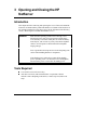
3 Opening and Closing the HP NetServer ................................................... 29
Introduction ................................................................................................. 29
Tools Required ............................................................................................ 29
Removing the LH 6000r Rack Mount Covers ............................................... 30
Replacing the LH 6000r Rack Mount Covers................................................ 33
Removing the LH 6000 Pedestal Covers...................................................... 34
Replacing the LH 6000 Pedestal Covers...................................................... 36
iii
Contents
4 Installing Mass Storage Devices............................................................... 39
Introduction ................................................................................................. 39
Mass Storage Guidelines............................................................................. 40
Selecting SCSI Devices........................................................................... 40
SCSI Termination .................................................................................... 40
Hot-Swap Cage Configuration ................................................................. 40
Boot Priority................................................................................................. 43
Installing Hot-Swap Mass Storage ............................................................... 44
Removing a Hot-Swap Hard Disk Drive Module ....................................... 48
Installing Non-Hot-Swap Mass Storage........................................................ 48
Non-Hot-Swap SCSI Addressing ............................................................. 50
Connecting SCSI Sub-systems.................................................................... 51
Integrated HP NetRAID ............................................................................... 51
Secondary Hot-Swap Mass Storage Cage ............................................... 51
Single and Dual SCSI Bus Configuration ................................................. 51
5 Installing Additional Memory .................................................................... 53
Introduction ................................................................................................. 53
Memory Guidelines...................................................................................... 53
Installing Memory in the LH 6000r and LH 6000........................................... 54
6 Installing Additional Boards ..................................................................... 59
Introduction ................................................................................................. 59
Guidelines ................................................................................................... 60
IRQ Settings............................................................................................ 61
Boot Priority............................................................................................. 61
Tested PCI Boards and Drivers.................................................................... 61
Installing Accessory Boards ......................................................................... 62
PCI Hot Plug Boards.................................................................................... 67
Removing a Hot Plug Board .................................................................... 68
7 Installing Additional Processors............................................................... 71
Introduction ................................................................................................. 71
Configuration Guidelines.............................................................................. 71
Installing the Processor................................................................................ 72
Setting the Processor Speed........................................................................ 76
Upgrading the Firmware .............................................................................. 77
Testing the Processor .................................................................................. 78
Re-installing the NOS .................................................................................. 78
iv
Contents
Removing a Processor Module .................................................................... 78
8 Installing the HP NetServer in an HP Rack System/E or Rack System/U 79
Introduction ................................................................................................. 79
HP NetServer and Rack Components.......................................................... 79
Tools Required ........................................................................................ 80
Rack-mounting Guidelines and Precautions................................................. 80
System E/U Characteristics ......................................................................... 82
HP NetServer Rack Mount Parts List ....................................................... 83
Rack-Mounting the HP NetServer ................................................................ 83
Marking your Front Column Baseline and Slide Mounting Holes............... 83
Installing Bezel Rack Nuts ....................................................................... 84
Installing Bar Nuts ................................................................................... 85
Attaching the Slides................................................................................. 86
Installing the NetServer ............................................................................... 89
Securing the HP NetServer to the Rack ....................................................... 92
Attaching the Cable Management Arm..................................................... 95
Attaching the Z-bracket for shipping......................................................... 97
9 Connecting the Monitor, Keyboard, and Mouse....................................... 99
10Configuring the HP NetServer..................................................................101
Introduction ................................................................................................101
HP NetServer Navigator CD-ROM ..............................................................104
Using a Separate Workstation to View Navigator Information – Resource
Mode......................................................................................................105
Using the Navigator CD-ROM on the NetServer – Server Mode ..................107
HP NetServer Navigator CD-ROM Main Menu........................................108
README File .........................................................................................108
Configuration Assistant and Installation Assistant ...................................108
Running Configuration Assistant and Installation Assistant......................109
NOS Installation .........................................................................................113
HP Management Solutions .........................................................................114
TopTools for Servers ..............................................................................114
TopTools Remote Control.......................................................................115
PcANYWHERE32...................................................................................116
NetServer Utilities...................................................................................116
Setup Utility ................................................................................................117
Starting the Setup Utility .........................................................................117
v
Contents
Menu Bar ...............................................................................................117
Using the Setup Screens ........................................................................119
Changing the System Date and Time......................................................119
Setting the HP NetServer’s Boot Passwords ...........................................120
Changing Internal Device Boot Priority....................................................124
Clearing Configuration Settings from CMOS ...........................................126
Run Symbios Configuration Utility...........................................................127
Verify Disk Drive Modules.......................................................................130
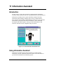
11Information Assistant...............................................................................131
Introduction ................................................................................................131
Using Information Assistant ........................................................................131
General Information................................................................................132
NetServer E-Series.................................................................................132
NetServer L-Series .................................................................................132
NetServer Accessories ...........................................................................132
Server Management ...............................................................................133
Getting Help ...........................................................................................133
Finding Information.................................................................................133
Copying and Printing Information ............................................................135
Installing HP Information Assistant Software ...............................................135
Installing from the CD-ROM....................................................................135
12Troubleshooting .......................................................................................137
Troubleshooting Tools ................................................................................137
Common Installation Problems ...................................................................139
Troubleshooting Sequence .....................................................................139
If the System Does Not Power On ..........................................................140
If the System Powers On, but Fails POST...............................................140
If the System Passes POST, but Does Not Function ...............................141
DiagTools...............................................................................................141
Error Messages ..........................................................................................143
Clearing the System Configuration..............................................................143
Password Problems....................................................................................145
13Alternative Rack Mounting.......................................................................147
Introduction ................................................................................................147
Rack-mounting Guidelines and Precautions................................................148
Preparing for Installation .............................................................................149
vi
Contents
Tools Required .......................................................................................149
Installing the Slides.....................................................................................150
Marking the Columns..............................................................................150
Installing Rack Nuts................................................................................151
Installing Bar Nuts ..................................................................................152
Attaching the Slides................................................................................153
Completing the HP NetServer Installation ...............................................155
A Specifications ...........................................................................................157
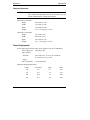
Video..........................................................................................................157
2D Video Resolutions .............................................................................157
3D Video Resolutions .............................................................................157
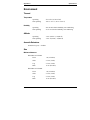
Environment ...............................................................................................158
Thermal..................................................................................................158
Altitude ...................................................................................................158
Acoustic Emissions.................................................................................158
Size........................................................................................................158
Power Requirements ..............................................................................159
B Regulatory Information ............................................................................161
Regulatory Notices - Electromagnetic Compliance ......................................161
Notice for United States..........................................................................162
Notice for Canada (Industry Canada)......................................................163
Notice for Japan .....................................................................................163
Notice for Korea .....................................................................................164
Notice for Taiwan....................................................................................165
Declaration of Conformity (US, EU, Australia) .........................................166
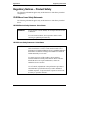
Regulatory Notices – Product Safety...........................................................167
CD-ROM and Laser Safety Statements...................................................167
Battery Statements .................................................................................169
Power Line Harmonic Statement ............................................................170
Noise and Ergonomic Statement ............................................................170
C Service and Support.................................................................................171
D Warranty and Software License...............................................................173
Warranty ....................................................................................................173
HP Software Product License Agreement ...................................................173
Index..............................................................................................................175
vii
1
Setting Up the HP NetServer
LH 6000/6000r
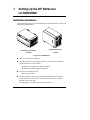
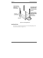
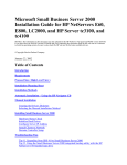
Installation Guidelines
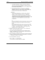
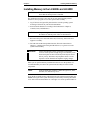
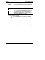
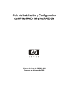
This Installation Guide is for the LH 6000r rack-mount HP NetServer, and the LH
6000 pedestal HP NetServer.
Rack-Mount Orientation
Pedestal Orientation
LH 6000r
LH 6000
Figure 1-1. HP NetServers
l Observe all warnings and cautions.
l Read this chapter before taking the NetServer out of its box. It lists what to
do and in what order. Choose either:
◊
HP NetServer LH 6000r rack-mount installation
◊
HP NetServer LH 6000 pedestal installation
l Unique to the LH 6000r are the:
◊
Bezel hinge and latch
l Use the removable and reusable rack-mounting handles to move and place
the LH 6000r in the rack. Remove them only when you have secured the
NetServer to the rack slides.
The LH 6000 has a locked bezel; the LH 6000r does not.
1
Chapter 1
Setting Up the HP NetServer LH 6000/6000r
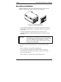
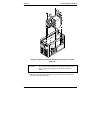
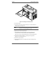
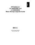
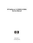
Rack Mount Installation
Follow the setup steps in the exact order shown below for a successful rack
installation. Skip any steps that do not apply to your installation.
Figure 1-2. LH 6000r (Rack-Mount)
1. As you unpack the shipping box, verify contents against the Contents List
included with your HP NetServer. If anything is missing or damaged, call
your reseller.
Store the empty boxes and packing material in a safe place. This is
especially important if you plan to ship the NetServer elsewhere for final
installation.
WARNING
The HP NetServers LH 6000r and LH 6000 each weigh up to
175 pounds (80 kgs). More than one person is required to lift a
server. Do not attempt to lift the NetServer by yourself.
Failure to observe this warning could result in serious injury,
or damage to the HP NetServer.
2. Familiarize yourself with the HP NetServer’s controls, indicators, and
ports.
Refer to Chapter 2, "Controls, Ports, and Indicators."
3. If you have optional internal items to add to the NetServer (memory,
accessory boards, mass storage, or processors), remove covers and the
bezel. If not, skip to step 8.
Refer to Chapter 3, "Opening and Closing the HP NetServer."
2
Chapter 1
Setting Up the HP NetServer LH 6000/6000r
4. If you have items such as a processor and DIMMs to install, HP
recommends that you remove the system board assembly from the server
chassis and install them at this time.
Refer to Chapter 5, "Installing Additional Memory," and Chapter 7,
"Installing Additional Processors."
5. Install PCI hot-plug and non-hot-plug accessory boards in the HP
NetServer.
Refer to Chapter 6, "Installing Additional Boards."
6. Install internal non-hot-swap mass storage devices such as hard drives and
tape back-ups into the front of the HP NetServer.
Refer to Chapter 4, "Installing Mass Storage Devices."
7. Reconnect internal cables as needed.
NOTE
If you removed the system board assembly, wait to replace it in
the chassis until after the server is in the rack. This reduces the
weight of the server making it easier to mount.
8. Install the server in the rack.
Refer to Chapter 8, "Installing the HP NetServer in an HP Rack System/E
or Rack System/U," or Chapter 13, "Alternative Rack Mounting."
9. If necessary, re-install the system board assembly in the rack-mounted
chassis.
10. Replace covers, but not the bezel.
Refer to Chapter 3, "Opening and Closing the HP NetServer."
11. Install hot-swap mass storage devices into the front of the HP NetServer.
Refer to Chapter 4, "Installing Mass Storage Devices."
12. Replace the bezel.
Refer to Chapter 3, "Opening and Closing the HP NetServer."
13. Install additional power supplies at the rear of the HP NetServer.
14. Install the Cable Management Arm to the rear of the rack-mounted HP
NetServer.
Refer to Chapter 8, "Installing the HP NetServer in an HP Rack System/E
or Rack System/U."
3
Chapter 1
Setting Up the HP NetServer LH 6000/6000r
15. Hook up the monitor, keyboard, and mouse.
Refer to Chapter 9, "Connecting the Monitor, Keyboard, and Mouse."
16. Connect external cables.
17. Power up the HP NetServer.
Refer to Chapter 2, "Controls, Ports, and Indicators."
18. Go to the section "Configuring the HP NetServer" at the end of this
chapter.
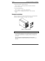
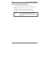
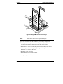
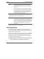
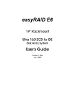
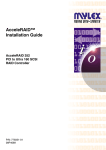
Pedestal Installation
Follow the setup steps in the exact order shown below for a successful pedestal
installation. Skip any steps that do not apply to your installation.
Figure 1-3. LH 6000 (Pedestal)
CAUTION
Unlock bezel before removing it.
1. As you unpack the shipping box, verify contents against the Contents List
included with your HP NetServer. If anything is missing or damaged, call
your reseller.
Store the empty boxes and packing material in a safe place. This is
especially important if you plan to ship the NetServer elsewhere for final
installation.
4
Chapter 1
Setting Up the HP NetServer LH 6000/6000r
CAUTION
The HP NetServers LH 6000r and LH 6000 each weigh up to
180 pounds (82 kgs). More than one person is required to lift a
server. Do not attempt to lift the NetServer by yourself.
Failure to observe this warning could result in serious injury,
or damage to the HP NetServer.
2. Familiarize yourself with the controls, ports and indicators.
Refer to Chapter 2, "Controls, Ports, and Indicators."
3. If you have optional internal items to add to the NetServer (memory,
accessory boards, mass storage, or processors), remove covers and the
bezel. If not, skip to step 8.
Refer to Chapter 3, "Opening and Closing the HP NetServer."
4. To install a processor and DIMMs, HP recommends that you remove the
system board assembly from the server chassis and install them at this
time.
Refer to Chapter 5, "Installing Additional Memory," and Chapter 7,
"Installing Additional Processors."
5. Install PCI hot-plug and non-hot-plug accessory boards in the HP
NetServer.
Refer to Chapter 6, "Installing Additional Boards."
6. Install internal non-hot-swap mass storage devices such as hard drives and
tape back-ups into the front of the HP NetServer.
7. Install the system board assembly into the NetServer if you removed it.
8. Install hot-swap mass storage devices into the front of the HP NetServer.
Refer to Chapter 4, "Installing Mass Storage Devices."
9. Reconnect all internal cables.
10. Replace covers and the bezel.
Refer to Chapter 3, "Opening and Closing the HP NetServer."
11. Install additional power supplies at the rear of the HP NetServer.
12. Connect the monitor, keyboard, and mouse.
Refer to Chapter 9, "Connecting the Monitor, Keyboard, and Mouse."
13. Connect external cables.
5
Chapter 1
Setting Up the HP NetServer LH 6000/6000r
14. Power up the HP NetServer.
Refer to Chapter 2, "Controls, Ports, and Indicators."
Go to the next section, "Configuring the HP NetServer."
Configuring the HP NetServer
1. Turn on the monitor. Press the power-on button on the HP NetServer, and
press the eject button on the CD-ROM drive. Place the HP NetServer
Navigator CD-ROM in the drive and close the drive. Press the Reset
button. If the system fails to restart, follow the instructions on the screen.
NOTE
To fully configure the HP NetServer, all the rack components
must be cabled and online (though not necessarily installed in
the rack.) If printed instructions are required; a local or
network printer must be connected.
Refer to Chapter 10, "Configuring the HP NetServer."
2. When HP Navigator starts, you can set the time and date, and change the
display language.
3. Read the README File: Select "README File" from the HP Navigator
Main Menu. The README file contains the latest information to help you
install your HP NetServer.
4. Run DiagTools: To verify the NetServer hardware as shipped, run
DiagTools by first creating a DiagTools flexible diskette(s) from the HP
NetServer Navigator CD-ROM. For more information on how to use
DiagTools to detect all processors and memory on the system board, refer
to the online NetServer DiagTools Error Reference and User Guide.
5. Install Information Assistant: It is easier to use Information Assistant from
a standalone workstation than from the NetServer where you are
performing the installation. Install Information Assistant from the HP
NetServer Online Documentation CD-ROM.
Go to Chapter 11, "Information Assistant," for information on how to
access your online documentation.
6
Chapter 1
Setting Up the HP NetServer LH 6000/6000r
NOTE
Before proceeding with the next steps, determine the storage
management mode (HP NetRAID or LVD SCSI) to be used on
the NetServer.
l If HP NetRAID is the desired mode, refer to the Integrated
HP NetRAID Controller Configuration Guide to plan the
RAID configuration.
l If LVD SCSI is the desired mode, run Setup Utility to
change from the default RAID mode to the LVD SCSI mode.
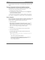
6. Run Configuration Assistant and Installation Assistant: Select
"Configuration and Installation Assistant."
7. Configure Mass Storage. This HP NetServer ships with the hot-swap mass
storage device(s) NetRAID enabled. To configure the drive(s), either:
◊
Run HP NetRAID Assistant to configure one or more RAID logical
drives. To run HP NetRAID Assistant, select "Execute" from the
Configure Disk Array screen. For detailed information on HP
NetRAID, refer to the Integrated HP NetRAID Controller
Configuration Guide.
or
◊
Restart the HP NetServer.
a. Press function key [F2] when prompted on the boot screen to enter
the Setup Utility.
b. In the Configuration menu, select Embedded LAN and SCSI
Settings.
c. Use the space bar to change the SCSI setting from HP NetRAID to
LVD SCSI.
d. Press function key [F10] to save the configuration and exit the
utility program.
e. Answer "Yes" to the question "Save Configuration and Exit Now?"
The HP NetServer will reboot, and HP Navigator will restart.
8. Select the configuration mode from the next screen. Three configuration
modes are available. Refer to Chapter 10, "Configuring the HP NetServer."
9. Choose a NOS. Select the NOS and version to be installed.
10. Select the NOS installation mode: If you select certain versions of Novell
NetWare or Microsoft Windows NT Server, you will be asked, "Would
you like to use HP’s automated mode of NOS installation?"
7
Chapter 1
Setting Up the HP NetServer LH 6000/6000r
◊
Select "Yes" to choose automated NOS installation for first-time
installation of Novell NetWare or Microsoft Windows NT Server on a
factory-configured HP NetServer.
◊
Select No to use the manual NOS installation if:
∗
You are installing a NOS other than Novell NetWare or Microsoft
Windows NT Server.
∗
You have replaced accessory components.
∗
You have replaced HP accessories with non-HP accessories.
11. View Configuration Advisories: Read the Configuration Advisories and
print them if necessary. Make any changes suggested in the advisories.
12. Configure Remote Management: If you plan to manage the HP NetServer
LH 6000 remotely, refer to the HP NetServer Server Management
Reference Guide for instructions. Select "Configure Remote Management"
on the Navigator screen to configure Integrated Remote Assistant.
13. Show System Information: Select "View System Information" to get
information about accessory boards and devices. Select "View Resources"
to view used and available system resources.
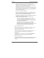
14. Install the NOS: If you selected the HP automated NOS installation
process, you will be guided through the process by a series of HP display
screens:
◊
Install Utility Partition: This step creates a disk utility partition on the
server boot hard disk drive where HP Navigator will copy
troubleshooting and other utilities.
NOTE
8
Select "Execute" on the Install Utility Partition screen to install
the partition. The utility partition is not available under SCO
UnixWare.
◊
Execute Card Utilities: Select "Execute" on the Execute Card Utilities
screen to run the accessory board configuration utilities.
◊
Follow the instructions on the screen and in the network operating
system’s installation instructions to perform the manual NOS
installation.
◊
For Manual NOS Installation Only: Before you perform a manual NOS
installation, print out instructions and create NOS-specific driver
diskette(s), as follows:
Chapter 1
Setting Up the HP NetServer LH 6000/6000r
a. Create Drivers Diskette(s): On the Create Drivers Diskette(s)
screen, select Create Drivers Diskette(s) to create one or more
customized diskettes containing HP drivers and configuration files
to use when you install the NOS.
b. Print and Read Instructions: On the Show NOS Installation
Instructions screen, select "Save to Disk" to copy the NOS
installation instructions to disk. Then print them from disk. Read
the instructions and follow them to install the NOS.
◊
Install NOS:
∗
Automated NOS Installation: For certain versions of Novell
NetWare or Microsoft Windows NT Server, Configuration
Assistant formats and partitions the hard disk drive. Installation
Assistant then guides you through the NOS installation and
configures the NOS with the appropriate drivers for the HP-bundled
configuration or for network interface cards on HP’s Tested
Configurations.
or
∗
Manual NOS Installation: Follow the instructions on the screen and
the network operating system installation instructions that you
printed.
∗
If HP NetRAID mode has been selected, you may need to install
NetRAID drivers and the NOS specific configuration utility. Refer
to Chapter 6, "HP NetRAID Software" of the Integrated HP
NetRAID Controller Configuration Guide.
15. Install HP TopTools: Refer to the HP NetServer Server Management
Reference Guide and install HP TopTools.
If you plan to manage HP NetRAID mode over the network, refer to
Chapter 8, "Managing Servers over the Network," of the Integrated HP
NetRAID Controller Configuration Guide.
16. Refer to Information Assistant on the HP NetServer Online Documentation
CD-ROM, for further information about your HP NetServer. See Chapter
11, "Information Assistant," for information.
17. Test and troubleshoot as necessary.
Refer to Chapter 12, "Troubleshooting."
Your LH 6000r or LH 6000 installation is complete.
9
Chapter 1
Setting Up the HP NetServer LH 6000/6000r
Shipping the fully-configured HP NetServer
Label each cable and component to facilitate re-assembly.
l If racked, remove all components from the rack, including external mass
storage.
l For both rack-mounted and pedestal HP NetServers, repack the
components in the original packing material, and prepare them for
shipment.
CAUTION
10
It is critical to disassemble and repackage all electronic
components before reshipment. Electronic components
(especially hard disk drives) can sustain damage when shipped
in rack enclosures.
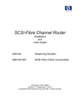
2 Controls, Ports, and Indicators
Front View
Figure 2-1 shows the rack-mounted HP NetServer LH 6000r and Figure 2-2 shows
the pedestal HP NetServer LH 6000.
Protective
Cover
(shown open)
Reset
Front Panel
Console
Figure 2-1. LH 6000r Bezel and Front Panel Console
NOTE
A small protective cover is provided on the HP NetServer’s
front bezel to cover the Power and Reset buttons. This cover
can prevent someone from accidentally powering down or
resetting the NetServer during normal operation. It can also be
easily opened for access to the Power and Reset buttons.
11
Chapter 2
Controls, Ports, and Indicators
Lock
Protective
Door
(shown open)
Reset
Front Panel
Console
Figure 2-2. LH 6000 Bezel and Front Panel Console
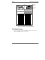
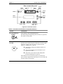
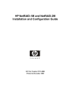
Front Panel Console
Figure 2-3 shows the HP NetServer LH 6000’s Front Panel Console (the HP
NetServer LH 6000r is similar, but has no lock).
12
Chapter 2
Controls, Ports, and Indicators
Door reveals this panel
Power-on
LED
Power
Switch
Lock
Reset
Switch
Reset
Secure
Mode
Switch
Secure
Mode
LED
Server
Status
LEDs
Status
Screen
Escape Enter
Scroll Scroll
Down Up
Figure 2-3. Front Panel Console
Table 2-1. Front Panel Console Switch and Indicator Definitions
Control
Description
Lock (LH 6000 only)
Locked
Locks system to prevent unauthorized use.
Note that locking and unlocking of the enclosure is reported to
the system event log (SEL).
Open
DC Power Switch
and LED
Turns the NetServer on and off. This switch is under the
protective door on the front panel. Push once to turn on, again
to turn off. As long as the AC power is connected to the
NetServer, standby power is present.
l If the LED is steady green, then the NetServer is
powered-up.
l If the LED is flashing green, the NetServer is in
a power-save mode.
l If the LED is off, but the two-line display has a
message, standby power is present.
If the NetServer is set up to go into power-save mode, the
power switch is depressed; you must press it for more than four
seconds to effect a power down.
13
Chapter 2
Controls, Ports, and Indicators
Control
Description
Resets the NetServer. This switch may be disabled by Secure
mode.
RESET
Secure Mode Switch
and Indicator
Locks system keyboard, monitor display, and control panel to
prevent unauthorized use. Go to the Setup utility security menu
to configure this feature. Secure Mode LED illuminates when
Secure Mode is enabled.
Status screen
Reports system status. For details, see the following section:
"Viewing System Information."
Server Status LEDs
Three LEDs -- one red, one yellow, one green -- are on the
right side of the front panel console. They give you a quick
idea of the NetServer’s general health. The signals provided
reflect the most critical pending event in the system.
Red
Yellow
Green
Red
Yellow
Green
Indicates NetServer Status:
Off
Off
Off
Main power is off and the NetServer may or may not
be on standby power.
Flashing
Off
Off
Immediate attention required due to a failed
component in the NetServer. The NetServer may not
be fully operational due to this condition. An audible
alarm may also be enabled.
Off
Flashing
Off
Attention required due to a pre-failure condition. This
condition may be caused by a component failure (for
example, a redundant fan or power supply) or an open
access panel that could lead to a critical component
failure, such as a processor module exceeding its
operating temperature. If the failed component is
redundant, the NetServer may still be operating
normally. An audible alarm may also be enabled.
Off
Off
On
The NetServer is operating normally.
14
Chapter 2
Controls, Ports, and Indicators
Viewing System Information
Use the HP NetServer’s status screen to view system configuration information, a
log of current and past conditions, replaceable parts information, adjust screen
contrast, and more.
Use the controls to choose menus and scroll through screens. Table 2-2 briefly
describes the controls.
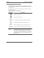
Table 2-2. Front Panel Console Buttons
Button Name
Escape
Enter
Down Arrow
Description
Return to previous menu.
Select an item from a menu.
Scroll down one line through the current screen or menu.
Up Arrow
Scroll up one line through the current screen or menu.
Left Arrow
Decrease contrast (when Adjust Contrast menu selected)
Right Arrow
Increase contrast (when Adjust Contrast menu selected)
NOTE
The front panel console display buttons and menus operate
even when the NetServer has powered down or hung, as long
as the NetServer is plugged into its power source. During
POST (power-on self-test) the buttons and menus are disabled
temporarily so that the status screen can display POST and
boot messages.
15
Chapter 2
Controls, Ports, and Indicators
Main Menu
This is the status screen default display:
HP NetServer
LH 6000
1. To reach the main menu from this default screen, press the Enter button.
NOTE
The status screen displays two lines of an entire menu at a
time.
This is the entire Main Menu:
***Main Menu****
>Event Log
>FW Info
>System Info
>Component Info
>Service
>Adjust Contrast
Menus beginning with a greater-than symbol (>) indicate sub-menu
selections.
2. Use the arrow buttons to move the cursor to your selection and press the
Enter button.
A cursor highlights the currently selected line.
3. To return to the Main Menu from one of these selections, press Escape.
4. To exit the Main Menu, press Escape.
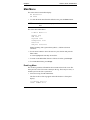
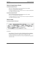
Event Log Menu
The Event Log menu has information about current and resolved events. The
menu provides a list of all events currently in the log. These may be errors, or
normal system events like a system boot.
1. Select Event Log from the Main Menu.
The first two lines of the log appear on the HP NetServer’s front panel
display:
****Event Log****
>008^ POWER Unit
16
Chapter 2
Controls, Ports, and Indicators
2. Use the arrow buttons to see the complete list.
This is a sample event log:
****Event Log****
>008^ POWER Unit
>007^ Temp Error
>006 CPU Failure
>005 POST Error
>004 Volt Error
>003 CPU Failure
>002^ POWER Unit
>001 System Boot
Each line includes a brief summary of a log entry, including the log entry
number. An "^" on a log entry means the problem is current.
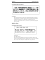
3. To read the complete log for an event, use the arrow keys to select the
entry and press Enter.
An example of a complete log, providing details about two events, 001 and
008, appears below.
>001 System Boot
Entry #001
07 /22 /99
10 :27 :15
System Boot
Event
>008 POWER Unit
Entry #008
Critical Pending
07 /22 /99
10 :27 :15
Proc. 2 FRB3
Failure
4. Use the arrow keys to scroll through the entire log.
5. To return to the Event Log menu, press Escape.
6. Press Escape again to return to the Main Menu.
17
Chapter 2
Controls, Ports, and Indicators
FW Info (Firmware Information) Menu
The FW Info menu displays the versions of all firmware components in the
system.
1. Select FW Info from the Main Menu.
A display similar to the one shown below appears on the HP NetServer’s
front panel display.
**FW Info***
2. Use the arrow buttons to scroll down through the rest of the information.
3. Press Escape to return to the Main Menu.
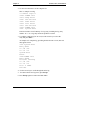
System Info Menu
The System Info menu displays the HP NetServer’s configuration information.
Information includes the number, speed, and type of CPUs, cache information,
and the amount of RAM on each memory board.
1. Select System Info from the Main Menu.
A display similar to this appears on the HP NetServer’s status screen.
**System Info***
No. Of CPUs=x
2. Use the down-arrow button to scroll through the rest of the information.
A full screen of the display would appear as shown below, but the actual
display is still limited by two viewing lines at time.
**HW Sys Info***
No. Of CPUs=x
CPU speed 500MHz
CPU type PIII Xeon
LFT CPU1 stepping xx
LFT CPU2 stepping xx
RFT CPU1 stepping xx
RFT CPU2 stepping xx
L2 Cache xxxx KB
Mem slot1 xxxxMB
Mem slot2 xxxxMB
3. Press Escape to return to the Main Menu.
18
Chapter 2
Controls, Ports, and Indicators
Component Info Menu
To see the NetServer chassis’ part numbers and serial numbers:
1. Select Component Info from the Main Menu.
A display similar to the one shown below appears on the status screen:
*Component Info*
Asset Tag:
2. Use the down-arrow button to scroll through the rest of the information.
An example of a full screen display appears below.
*Component Info*
Asset Tag:
AAAAAAAAAAAAAA
Product Part:
nnnn-nnnn
Product Serial
AAAAAAAAAAAAAA
Chassis Part:
nnnn nnnn
Chassis Serial:
AAAAAAAAAAAAAA
3. Press Escape again to return to the Main Menu.
Adjust Contrast Menu
This is the Adjust Contrast display.
*Adjust Contrast
== {XXXXXXXX}==
1. Decrease contrast by pressing
2. Increase contrast by pressing
or
or
.
.
3. To save the contrast setting, press Enter.
19
Chapter 2
Controls, Ports, and Indicators
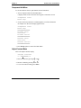
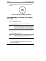
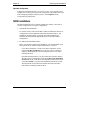
Hard Disk Drive LED Indicators
Each disk drive module has two LED indicators: one for status and one for
activity. You can view these LED indicators on the LH 6000 and on the LH 6000r
with the bezel open. For more information on hard drives, see Chapter 4,
"Installing Mass Storage Devices."
Light pipes on the disk drive modules transmit light to the indicators from LEDs
mounted on the hot-swap mass storage cage. Verify that the LED indicators show
the correct status and activity for all of the installed disk drives.
Status
Activity
Figure 2-4. Disk Drive LED Indicators
Table 2-3. Disk Drive LED Indicators
Status LED Indicator
Activity LED Indicator
Off: Drive not present, or not connected to
the cage
Off: No Drive activity
Green: Drive normal
Green (flashing): Accessing Drive
Amber (flashing): Drive failure predicted
Green (solid for more than one
minute): Drive spinning up, or
"hung"
Red (fast flashing): Drive fault
Red (solid): Drive power fault
20
Chapter 2
Controls, Ports, and Indicators
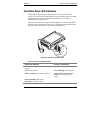
Indicators and Controls behind the Front Bezel
The LEDs for these devices are visible only when the bezel is open or removed:
l CD ROM
l DAT
l Flexible Disk Drives
l Internal Hard Disk Drives
Flexible
Disk Drive
Headphone
Jack
Activity
LED
CD ROM
Drive
Activity
LED
Eject
Button
Access
Button
Volume
Control
Internal
Drive
Bays
Figure 2-5. Flexible Disk Drive and CD-ROM LEDs
21
Chapter 2
Controls, Ports, and Indicators
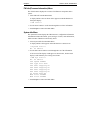
Rear View
The HP NetServer’s rear panel includes communication ports, the AC power
connectors, and the NetServer’s two power supplies cages. Each power supply
cage can hold two power supply modules. In addition, all hot plug PCI slots have
LED indicators located just above the PCI latch.
Serial Port
Parallel Port
1
2
Mouse Port
3
Keyboard Port
4
5
6
LAN Port
Monitor Port
7
8
1
2
3
Hot Plug
PCI LEDs
4
Power
Supply
Cages (2)
Power
Supply
Modules
(4 max.)
Power
Connectors
Power Module
Status LEDs
Figure 2-6. Rear Panel of the HP NetServer
22
Remote
Management
Port
Chapter 2
Controls, Ports, and Indicators
LED Indicators at the Rear of the Chassis
PCI Attention LED Indicators
If a hot-plug board needs attention, its LED indicator glows amber.
1
2
3
4
5
6
7
8
Slot 5 needs
attention
Figure 2-7. Amber Attention LED Indicator
When an amber PCI LED indicator appears, you must remove the cover to see the
power LED indicators for each hot-plug PCI slot. See Chapter 3, "Opening and
Closing the HP NetServer."
PCI Power LED Indicators (Internal)
Pairs of very small LED indicators are located on the I/O board above each of the
hot-plug PCI slots.
Power (Green)
Attention (Amber)
5
Figure 2-8. Onboard LED Indicators
Light from the small onboard LED indicators is transmitted through the light pipes
on the plastic slot ejectors.
23
Chapter 2
Controls, Ports, and Indicators
Onboard LEDs
Green (Power) LED
Amber (Attention) LED
Figure 2-9. Light Pipes Display PCI LED Indicators
PCI Slot LED Indicators
Each hot-plug PCI slot has an amber and a green LED. Table 2-4 interprets the
LEDs.
Table 2-4. PCI LED Indicator Status
Amber
Green
Status Indicated
Your Action
Off
On
Power to the slot is on, and
the slot is operating normally.
On
On
Power to the slot is on, but the Do not remove the board from the
slot needs attention.
slot.
On
Off
Power to the slot is off. The
slot needs attention.
You can safely remove the board
from this slot.
Off
Off
Power to the slot is off.
You can safely remove the board
from this slot.
Do not remove the board from the
slot.
For more information on PCI Hot Plug boards, see Chapter 6, "Installing
Additional Boards."
24
Chapter 2
Controls, Ports, and Indicators
Local Area Network (LAN) LEDs
The LAN has LEDs on the connector that provide status information about the
LAN. Interpret the LAN LEDs as shown in Table 2-5.
Table 2-5. Local Area Network LED Status
Green LED
Yellow LED
LAN Status:
ON/Flashing
OFF
The LAN is connected and data is being
transferred at 10Mbps.
ON/Flashing
ON
The LAN is connected and data is being
transferred at 100Mbps.
OFF
OFF
The LAN is not connected or is not operational
(see Chapter 12, "Troubleshooting").
Power Supplies
Each NetServer is shipped with three power supply blocks in the standard
configuration. An optional fourth power supply block can be added to provide
redundancy allowing power supplies to be hot-swapped.
Power Supply Status LEDs
Each power supply block has one green LED. Interpret the green LEDs on the
power supplies as shown in Table 2-6.
Table 2-6. Power Supply LED Status
Green LED
Steady Green
Off
NetServer Status:
The system is powered up.
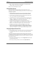
The AC line is unplugged or the power supply
has failed (see Chapter 12, "Troubleshooting").
Connecting the HP NetServer to AC Power
When you connect the NetServer to an AC power source, the server temporarily
draws additional current. This occurs even when the system is in standby mode.
This "inrush current" is much greater than the server’s normal operating needs.
Generally, your external AC power source can handle the inrush current.
If you install several HP NetServers on one circuit, precautions are necessary. If
there is a power failure and power is then restored, all the servers immediately
begin to draw inrush current at the same time. If the circuit breakers on the
incoming power line have insufficient capacity, they may trip and thus prevent the
servers from powering up.
25
Chapter 2
Controls, Ports, and Indicators
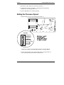
When preparing your site for installation, allow for the additional inrush current.
Follow these circuit breaker recommendations before installing the server at your
site:
• In North America, use a 20-amp-minimum circuit with one NEMA AB1
class 14B breaker for each 16-amp Power Distribution Unit (PDU).
• In Europe:
◊
For a single HP NetServer in a rack, use a 15-amp-minimum circuit
with one IEC MCB C-type breaker for each 16-amp PDU.
◊
For multiple HP NetServers in a rack, use a 15-amp-minimum circuit
with one IEC MCB D-type breaker for each 16-amp PDU.
NOTE
Each 16-amp PDU can accommodate a maximum of two HP
NetServers.
When the proper power supply is available, connect the NetServer to the AC
power source.
Power-Up and Power-Down Procedures
Power-Up Procedure
1. Ensure the NetServer’s power cords are connected to a power source and to
the power block(s) on the rear panel.
2. Press the power switch.
CAUTION
26
The power supplies continue to provide standby voltage to the
NetServer until the power cords are disconnected.
Chapter 2
Controls, Ports, and Indicators
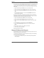
Power-Down Procedure
Follow this procedure when installing non-hot-swap and non-hot-plug
components, such as tape drives and non-hot-plug PCI boards.
1. Log off all users and back-up files.
2. Follow instructions in your network operating system (NOS)
documentation to gracefully shut down all networking software and
applications.
3. Press the Power switch to shut down the NetServer (see Figure 2-3).
Normally, this completes the procedure.
Sleep States (ACPI)
The HP NetServer supports the ACPI (Advanced Configuration and Power
Interface) standard, which is a key component of a NOS’s directed power
management. The supported features are only available when an ACPI-compliant
NOS is installed on the NetServer. The term “sleep state” refers to any of several
reduced power consumption states in which normal NOS activity has ceased.
The NetServer supports several sleep states, including a sleep state with a short
wake-up time, sometimes referred to as “standby” or “suspend” by various
operating systems. In this sleep state the NetServer appears to be off, indicated by
no display on the monitor and no activity for the CD-ROM or internal hard drives,
however, the power LED is slowly flashing and the fans are operating.
An additional sleep state supported by the NetServer is one with a slower wake-up
time, sometimes referred to as “hibernate” by various operating systems. In this
sleep state, the NetServer appears to be off as mentioned earlier, but the fans and
the power LED are also turned off. This sleep state's unique feature (and the
reason for its slower wake-up time) is that the NetServer's state (applications
running, screens open, etc.) just prior to hibernate has been saved to disk and must
be restored from disk upon wake-up. This method of restoring the NetServer's
operation is much faster than rebooting the NetServer, which would require
running all the start-up self-tests before starting the NOS.
The NetServer supports certain types of system activity, which is used as wake up
events from these sleep states. These wake-up events can be generated from the
power button, LAN activity, and scheduled events. The embedded Integrated
Remote Assistant also has the capability of waking up the NetServer.
27
Chapter 2
NOTE
Controls, Ports, and Indicators
The HP NetServer’s power management policies (transitions
between various power states) and the user options are specific
to the particular ACPI-compliant NOS installed on the
NetServer. If your respective NOS is ACPI-compliant, refer to
the power management features in the instructions provided for
more information.
The HP NetServer’s power button can be configured to initiate a sleep state (Sleep
button) or a “soft off” or graceful shutdown of the NOS, rather than an immediate
shut down of the power supply. The power button configurations are dependent on
the user interface provided by the ACPI-compliant NOS. While power
management is under the control of the ACPI-compliant NOS, the HP NetServer’s
power button is capable of an override in case of non-responsive NOS.
28
NOTE
The HP NetServer power button will force a power down
without waiting for the NOS to gracefully shut down, if the
power button is pressed and held for more than four seconds.
CAUTION
If the power button override is used, there is a strong
possibility of corrupted or lost data.
3 Opening and Closing the HP
NetServer
Introduction
This chapter describes removing and replacing the covers of the rack-mount HP
NetServer LH 6000r and the pedestal HP NetServer LH 6000. If the NetServer is
not currently installed in a rack, skip to step 6 for the LH 6000r in the following
section, "Removing the LH 6000r Rack Mount Covers."
WARNING
Shut down the operating system before removing covers.
Disconnect power cords to avoid exposure to high energy
levels that may cause burns when parts are short-circuited by
metal objects, such as tools or jewelry. Disconnect telephone
cables to avoid exposure to shock hazard from telephone
ringing voltages.
Wear a grounded wrist strap and use a static-dissipating work
surface when handling NetServer components.
Note that the power switch does not turn off the standby
power. (Standby power is on when the LCD is backlighted.)
Disconnect the power cords to turn off standby power.
Tools Required
l Torx 25 Driver (for rack access only)
l Anti-static service kit (3M 8501/8502/8503 or equivalent). This kit
includes a static-dissipating work surface, a chassis clip lead, and a wrist
strap.
29
Chapter 3
Opening and Closing the HP NetServer
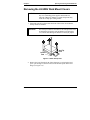
Removing the LH 6000r Rack Mount Covers
CAUTION
Do NOT operate the NetServer for more than 30 minutes with
any cover (including power supplies and disk drives)
removed. Otherwise, damage to system components may
result due to improper cooling airflow.
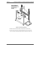
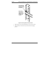
1. Extend the anti-tip foot from under the front of the rack or insure that the
anti-tip feature is installed.
WARNING
The anti-tip foot must be extended or the anti-tip feature must
be installed to prevent the rack and NetServer from tipping
over, which could damage the NetServer and injure people.
Leveler
Feet
Anti-Tip
Foot
Figure 3-1. Rack Anti-tip Foot
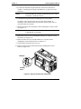
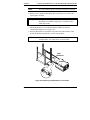
2. Remove the bezel from the front of the NetServer by swinging the bezel
open (past 90 degrees) until it releases from the three posts on the bezel
hinge (see Figure 3-2).
30
Chapter 3
Opening and Closing the HP NetServer
Figure 3-2. Removing the HP NetServer LH 6000r Bezel
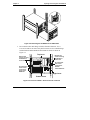
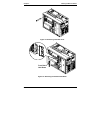
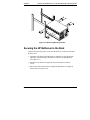
3. Do not unscrew the entire hinge or bracket from the NetServer. Use a
Torx 25 screwdriver to remove only the four outer screws so that the hinge
and the bracket remain attached to the NetServer chassis as shown in
Figure 3-3.
Top Cover
Remove two
screws securing
the NetServer
to the rack.
Remove two
screws securing
the NetServer
to the rack.
Do not remove
two screws
securing the
bracket
to the NetServer.
Do not remove
three screws
securing the
hinge to the
NetServer.
Right Cover
Bottom Cover
Figure 3-3. Front of LH 6000r - Screw and Cover Locations
31
Chapter 3
Opening and Closing the HP NetServer
4
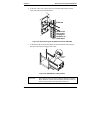
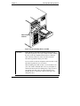
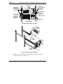
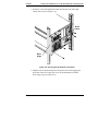
4. At the rear of the rack, remove the two screws that connect the Z-bracket
(if present) to the rear of the NetServer.
1
2
3
Z-Bracket
Remove the
two screws
holding the
NetServer to
the bracket.
Figure 3-4. Disconnecting the HP NetServer from the Z-Bracket
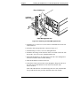
5. At the front of the rack, pull the NetServer forward from the rack until you
hear the lockout devices engage with a click.
Locking
Latch
Figure 3-5. Slide Mount Locking Latches
CAUTION
32
The NetServer covers are heavy. Support them as you remove
them, and allow room to move them away from the NetServer
and for storage when removed from the NetServer.
Chapter 3
Opening and Closing the HP NetServer
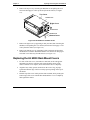
6. Remove the top cover by loosening the thumbscrew and pulling the cover
forward to disengage it. Lift it up and away from the chassis (see Figure
3-6).
Top Cover
Thumbscrew
Right Cover
Thumbscrew
Thumbscrew
Bottom Cover
Figure 3-6. HP NetServer LH 6000r Covers
7. Remove the right cover by supporting it with your hand, then loosening the
thumbscrew and pulling the cover forward, then down to disengage it. Lift
it away from the chassis (see Figure 3-6).
8. Remove the bottom cover by supporting it with your hand, and loosening
the thumbscrew with the other hand. Pull the cover forward to disengage it
and catch it as it falls away from the chassis (see Figure 3-6).
Replacing the LH 6000r Rack Mount Covers
1. For each of the side covers, insert the two metal tabs, at the end opposite
the handle, into the two openings at the top and bottom corners of the
chassis. Hold the cover in place, but do not slide the tabs in completely.
2. Align the four, widely spaced, metal tabs on the cover’s long, top edge
against the leftmost edge of the four widely spaced openings on the top of
the chassis.
3. Hold the top of the cover in this position with one hand, while pressing the
bottom edge of the cover with the other hand until the cover is completely
flush against the chassis.
33
Chapter 3
Opening and Closing the HP NetServer
4. Check that the four closely spaced metal tabs are in their four openings at
the rear of the HP NetServer. The cover is secure when all edges are flush
against the chassis and you cannot easily shift it.
5. Gently slide the cover until the back edge snaps into place.
6. Tighten the thumbscrew at the front of the side cover.
7. For the top cover, place the cover onto the chassis. Align the five tabs on
the left side of the cover with the slots in the chassis.
8. Slide the top cover back to the rear of the chassis and tighten the
thumbscrew.
9. Return the NetServer to the rack. Replace the screws removed from the
front and rear.
10. Hold the bezel at 90 degrees to the left side of the NetServer. Snap the
bezel clamps onto the hinge posts by pressing the bezel onto the hinge.
When the bezel is snapped into place, swing the bezel closed.
Removing the LH 6000 Pedestal Covers
CAUTION
Do NOT operate the NetServer for more than 30 minutes with
any cover (including power supplies and disk drives)
removed. Otherwise, damage to system components may
result due to improper cooling airflow.
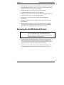
1. Unlock the bezel, using the supplied key, and remove the key from the
front of the NetServer. The bezel connects to the front of the NetServer
chassis with two snap-in connectors at the top front of the chassis and two
tabs that fit into two slots on the bottom front of the chassis.
2. To remove the bezel, pull it forward until it unsnaps, then lift the bezel
forward and upward from the chassis face (action 2 and 3 of Figure 3-7).
34
Chapter 3
Opening and Closing the HP NetServer
(1) Unlock the bezel.
(2) Pull bezel toward you, then
(3) up and away from the front panel,
releasing the tabs from the slots
at the bottom of the front panel.
2
3
1
Figure 3-7. Removing the HP NetServer LH 6000 Bezel
CAUTION
The NetServer covers are heavy. Support them as you remove
them, and allow room to move them away from the NetServer
and for storage when removed.
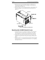
3. Remove the left cover by loosening the thumbscrew and then pulling the
cover forward to disengage it. Lift it outward and away from the chassis
(see Figure 3-8).
35
Chapter 3
Opening and Closing the HP NetServer
4. Remove the top cover by loosening the thumbscrew, pulling the cover
forward and then slightly sideways to disengage it. Lift it up and away
from the chassis (see Figure 3-8).
5. Remove the right cover by loosening the thumbscrew and pulling the cover
forward to disengage it. Lift it outward and away from the chassis (see
Figure 3-8).
Top Cover
Left Cover
Right Cover
Figure 3-8. HP NetServer LH 6000 Covers
Replacing the LH 6000 Pedestal Covers
1. For each of the side covers, insert the two metal tabs, at the end opposite
the handle, into the two openings at the top and bottom corners of the
chassis. Hold the cover in place, but do not slide the tabs in completely.
2. Align the four, widely spaced, metal tabs on the cover’s long, top edge
against the top edge of the four widely spaced openings on the top of the
chassis.
3. Hold the top of the cover in this position with one hand, while pressing the
bottom edge of the cover with the other hand until the cover is completely
flush against the chassis.
36
Chapter 3
Opening and Closing the HP NetServer
4. Check that the four closely spaced metal tabs are in their four openings at
the rear of the HP NetServer. The cover is secure when all edges are flush
against the chassis and you cannot easily shift it.
5. Gently slide the cover until the rear edge snaps into place.
6. Tighten the thumbscrew at the front of the cover.
7. For the top cover, place the cover onto the chassis. Align the five tabs on
the left side of the cover with the slots in the chassis.
8. Slide the top cover back to the rear of the chassis and tighten the
thumbscrew.
9. Replace the bezel by placing the two tabs at the bottom of the bezel into
the corresponding slots on the chassis and snapping the bezel into position
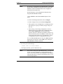
at the top of the chassis.
10. Lock the bezel using the supplied key and remove the key from the front of
the NetServer.
37
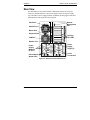
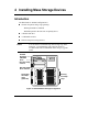
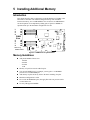
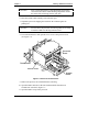
4 Installing Mass Storage Devices
Introduction
The HP NetServer standard configuration is:
l One hot-swap mass storage cage (primary)
◊
With requested drives installed
◊
With filler panels in the slots not occupied by drives
l A flexible disk drive
l A CD-ROM 32x drive
l Non-hot-swap mass storage shelves
NOTE
You can install a second hot-swap mass storage cage in the
NetServer. For information, refer to the HP NetServer
LH 3000/3000r and LH 6000/6000r Mass Storage Upgrade
Guide.
Flexible
disk drive
CD-ROM
drive
Non-hot-swap
shelves
Non-hot-swap
drive shelves
Secondary
hot-swap
cage
(optional)
Primary
hot-swap
cage
Figure 4-1. Standard Mass Storage Configuration
39
Chapter 4
Installing Mass Storage Devices
Mass Storage Guidelines
Read this section prior to installing mass storage drives for a successful
installation.
Selecting SCSI Devices
Hot-Swap
Hot-swap mass storage consists of either low profile (1.0-inch) or half-height
(1.6-inch) drives. For the hot-swap shelves use only HP LVD SCSI 3.5-inch hard
disk drives. HP hot-swap drives come set for LVD SCSI operation and without
device ID or termination. Do not change these settings.
Non-Hot-Swap
For the non-hot swap shelves, use 3.5-inch or 5.25-inch single-ended (SE) SCSI
devices. This bay supports either two half-height or three low profile devices. You
can order HP mounting kits for removable media devices or trays for 3.5-inch
hard disk drives (both low profile and half-height). You may use narrow/wide
SCSI adapters on these devices.
SCSI Termination
The internal SCSI cable for the non-hot-swap bays is terminated. The cable(s) for
the hot-swap storage cage(s) is(are) not terminated. Do not interchange cables.
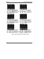
Hot-Swap Cage Configuration
A low profile drive fits within one slot. HP recommends you start configuring at
slot 1 (the slot nearest the bottom of the cage) to get optimum loading of the bus.
A half-height drive requires most of the space provided by two slots. Use a drive
spacer to close up the remaining space.
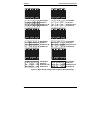
Figure 4-2 shows primary cage (SCSI A) and Figure 4-3 shows optional
secondary cage (SCSI B) configurations for the LH 6000r orientation. In
installations where the cage is not fully populated, add drives from the lowest
SCSI address (left most drive position) to the highest.
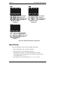
Figure 4-4 shows the configurations for duplex bus operation in the LH 6000r
orientation. Duplex bus operation requires the addition of the duplexing accessory.
40
Chapter 4
Installing Mass Storage Devices
1
1
0
A
2
2
1
A
3
3
2
A
4
4
3
A
5
5
8
A
6
6
9
A
Slot Number
Disk Drive
SCSI Device ID
SCSI Bus ID
1
1
0
A
2
3 4
2
2
A
5 6
3
8
A
Slot Number
Disk Drive
SCSI Device ID
SCSI Bus ID
1
1
0
A
2
3
2
2
A
4
3
3
A
5
4
8
A
6
5
9
A
Slot Number
Disk Drive
SCSI Device ID
SCSI Bus ID
1
1
0
A
2
3
2
2
A
4
5
3
8
A
6
4
9
A
Slot Number
Disk Drive
SCSI Device ID
SCSI Bus ID
1
1
0
A
2
3
2
2
A
4
3
3
A
5
Slot Number
Disk Drive
SCSI Device ID
SCSI Bus ID
1
1
0
A
2
2
1
A
3
3
2
A
4
4
5
5
8
A
6
6
9
A
Slot Number
Disk Drive
SCSI Device ID
SCSI Bus ID
6
4
9
A
Figure 4-2. Mass Storage Configurations (Primary Cage)
41
Chapter 4
Installing Mass Storage Devices
1 2 3 4 5
1 2 3 4 5
10 11 12 13 14
B B B B B
6
6
15
B
Slot Number
Disk Drive
SCSI Device ID
SCSI Bus ID
1 2
1
10
B
3 4
2
12
B
5 6
3
14
B
Slot Number
Disk Drive
SCSI Device ID
SCSI Bus ID
1 2 3 4 5 6 Slot Number
1
2 3 4 5 Disk Drive
10
12 13 14 15 SCSI Device ID
B
B B B B SCSI Bus ID
1
1
10
B
3 4 5 6
2
3 4
14 15
12
B B
B
Slot Number
Disk Drive
SCSI Device ID
SCSI Bus ID
1
1
10
B
1 2 3 4 5 6
1 2 3 4 5 6
10 11 12
14 15
B B B
B B
Slot Number
Disk Drive
SCSI Device ID
SCSI Bus ID
2
3 4
2 3
12 13
B B
5
6
4
15
B
Slot Number
Disk Drive
SCSI Device ID
SCSI Bus ID
2
Figure 4-3. Mass Storage Configurations (Optional Secondary Cage)
42
Chapter 4
1
1
0
B
Installing Mass Storage Devices
2 3 4 5 6
2 3 4 5 6
1 2 0 1 2
B B A A A
Bus A
Bus B
Center Line
1 2 3 4 5
1
2 3 4
0
2 0 1
B
B A A
Bus B
Bus A
Center Line
6
5
2
A
Slot Number
Disk Drive
SCSI Device ID
SCSI Bus ID
1
1
0
B
2
3
2
2
B
4
3
0
A
5
6
4
2
A
Slot Number
Disk Drive
SCSI Device ID
SCSI Bus ID
Bus A
Bus B
Center Line
Slot Number
Disk Drive
SCSI Device ID
SCSI Bus ID
Figure 4-4. Duplex Mass Storage Configurations
Boot Priority
This is the default boot priority for the LH 6000r and LH 6000:
1. IDE CD-ROM drive with a bootable CD-ROM
2. Flexible disk drive with a bootable flexible disk
3. Embedded SCSI controller or integrated HP NetRAID controller.
SCSI channel A precedes channel B. On a SCSI bus, boot order follows
the ascending order: 0, 1, 2, 3….
4. PCI boards in slots in descending order: 8, 7, 6, 5, 4, 3, 2, and 1
43
Chapter 4
Installing Mass Storage Devices
You can change this boot order using the Setup utility (press [F2] during
the boot process. See Chapter 10, "Configuring the HP NetServer."
NOTE
Use the Symbios (SCSI) Configuration Utility to configure the
HP NetServer to ignore the onboard SCSI channels and to
select a different PCI slot for boot devices. Refer to the
Symbios (SCSI) Configuration Utility on the HP NetServer
Online Documentation CD-ROM under Information
Assistant/NetServer LH 6000/LH 6000r/Configure.
Installing Hot-Swap Mass Storage
The procedure for installing additional hot-swap mass-storage is the same for all
HP NetServer versions.
CAUTION
Protect the drive from static electricity by leaving it in its
anti-static bag until you are ready to install it. Before handling
the drive, touch any unpainted metal surface to discharge
static electricity. When you remove the drive from the
anti-static bag, handle it only by the frame.
Do not touch the electrical components. Place the drive on the
anti-static bag whenever you set it down.
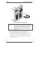
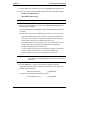
1.
Remove necessary filler panels:
a. Verify that the drive cage is unlocked prior to removing panels.
b. Press in the locking latch and insert your fingers.
c. Using your fingers, pull the blue filler panel straight out
(see Figure 4-5).
44
Chapter 4
Installing Mass Storage Devices
Figure 4-5. Hot-Swap Drive and Filler Panel
CAUTION
2.
When installing more than one drive, do not stack drives on
your work surface. Hard disk drives are very susceptible to
mechanical shock and can be damaged by a drop as short as
one-quarter of an inch. Take care when unpacking and
handling the drive. If the drop would crack an egg, it will
damage the drive.
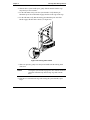
Drive spacers attach to the disk drive module with four small feet.
If you need to remove a drive spacer from a disk drive slot:
• Slide the drive spacer back, a fraction of an inch away from your body.
• Tilt up the front of the drive spacer to disengage the front two feet.
• Pull the drive spacer forward slightly to disengage the back two feet
and lift (see Figure 4-6).
45
Chapter 4
Installing Mass Storage Devices
Drive
Spacer
Figure 4-6. Removing the Drive Spacer
3. Open the drive module by pressing in on the locking latch at the end of the
drive ejector handle and pulling open the handle.
CAUTION
Be careful when you open the ejector handle. Extreme force
can snap off the handle. Be careful not to damage the light
pipes as you insert the drive. They are very fragile.
Locking tab
pivots when
the ejector
handle is open.
Light Pipes
(fragile)
Drive ejector
handle
Locking Latch
Figure 4-7. Readying Drive for Installation
46
Chapter 4
Installing Mass Storage Devices
4. With the drive ejector handle open, gently slide the module into the cage.
Stop when you feel resistance.
5. For the LH 6000r, slowly close the ejector handle. Verify that the pin
behind the pivot end of the handle engages the hole in the edge of the cage.
6. For the LH 6000, verify that the locking pin behind the pivot end of the
handle engages the hole in the chassis (see Figure 4-8).
Figure 4-8. Locking Tab Location
7. With even pressure, gently close the ejector handle until the locking latch
clicks shut.
NOTE
Closing the ejector handle engages the drive with the electrical
connector in the hot-swap mass storage cage and seats the
drive.
8. If the drive is unseated in the cage after closing the ejector handle, repeat
step 5.
47
Chapter 4
Installing Mass Storage Devices
Removing a Hot-Swap Hard Disk Drive Module
CAUTION
You must remove the drive slowly to ensure the drive heads
are parked prior to removal. Ensure you follow these
instructions carefully to prevent handling damage, such as
head slaps or head actuator unlocking.
1. To unlock the drive, push the locking latch in and then pull the ejector
handle toward you (see Figure 4-7).
2. Gently pull the drive out about an inch to disengage the power connection.
3. Wait about 30 seconds for the drive to stop spinning and the drive heads to
park.
4. Use your hand to support the bottom of the drive, while you slowly pull the
drive straight out. Do not allow the drive to fall.
5. Place the drive in an electrostatic protected container. Do not stack drives.
Installing Non-Hot-Swap Mass Storage
For information on device requirements and options, see the preceding section
entitled "Selecting SCSI Devices."
48
Chapter 4
Installing Mass Storage Devices
Non-hot-swap
shelves
Figure 4-9. Non-Hot-Swap Shelf in LH 6000
CAUTION
Protect the drive from static electricity by leaving it in its
anti-static bag until you are ready to install it. Before handling
the drive, touch any unpainted metal surface to discharge
static electricity. When you remove the drive from the
anti-static bag, handle it only by the frame.
Do not touch the electrical components. Place the drive on the
anti-static bag whenever you set it down.
When installing more than one drive, do not stack drives on
your work surface. Hard disk drives are very susceptible to
mechanical shock and can be damaged by a drop as short as
one-quarter of an inch. Take care when unpacking and
handling the drive. If the drop would crack an egg, it will
damage the drive.
49
Chapter 4
Installing Mass Storage Devices
To install a non-hot-swap, mass storage device, such as a flexible tape drive,
CD-ROM drive, tape back-up drive or hard disk drive.
The installation procedure is the same for the rack-mount and the pedestal
NetServers once you gain access to the server.
1. Log off all users and gracefully shut down the network operating system
according to directions in your NOS documentation.
2. Power down the NetServer according to the instructions in Chapter 2,
"Controls, Ports, and Indicators."
3. Disconnect the power cords and cables and, if necessary, label each one to
support re-assembly.
CAUTION
The power supplies will continue to provide standby current
to the NetServer until the power cables are disconnected.
4. For both rack-mounted and pedestal models, follow the instructions in
Chapter 3, "Opening and Closing the HP NetServer," to gain access to
server.
5. Select an available shelf for the device and remove the filler panel.
6. If the device you are installing is the boot device, check the boot priority.
7. Mount the device on a mass storage tray following the directions included
with the tray.
8. Slide the module into the shelf opening and secure the tray using the two
mounting screws included with the tray.
9. Connect the cable from the power supply and the SE SCSI cable from the
I/O board to the device.
10. Follow the procedure in Chapter 3, "Opening and Closing the HP
NetServer," for closing up the server.
11. Reconnect power and cables.
12. Restore NetServer to normal operation.
Non-Hot-Swap SCSI Addressing
Each SCSI device must have a unique SCSI address. Each device connected to
either of the SCSI connectors must have a unique address (narrow devices may
use addresses 0-6; wide devices may use addresses 0-15, except address 7).
Address 5 in the hot-swap cage is reserved for the SAF-TE interface. This address
is also excluded when the secondary hot-swap cage is installed.
50
Chapter 4
Installing Mass Storage Devices
Connecting SCSI Sub-systems
The second LVD SCSI connector, bus B, can be used to connect to peripheral
sub-systems such as the HP RS/12 or DLT tape libraries.
CAUTION
Do not mix high voltage differential (HVD) driver and
receiver devices with the SE, LVD (Ultra2), or multi-mode
devices on the same SCSI bus.
Integrated HP NetRAID
The HP NetServer contains an integrated HP NetRAID controller, which puts the
power of the HP NetRAID series of DACs (disk array controllers) in the
NetServer with no additional hardware.
Refer to the Integrated HP NetRAID Controller Configuration Guide for complete
information. You can also find the guide on the following HP web site:
http://www.hp.com/go/netserver
Secondary Hot-Swap Mass Storage Cage
You can install a second hot-swap mass storage cage in the NetServer. For
information, refer to the HP NetServer LH 3000/3000r and LH 6000/6000r Mass
Storage Upgrade Guide.
Single and Dual SCSI Bus Configuration
You can configure each hot-swap mass storage cage to operate as:
l A single SCSI bus with up to six drives
l Two independent SCSI busses with up to three drives on each buss
(requires optional duplex board accessory kit)
The advantage of the dual bus configuration is that you can put the drives for boot
and mirror functions on one bus and the drives for data on another.
51
5 Installing Additional Memory
Introduction
This chapter describes how to add memory to the HP NetServer LH 6000r or the
HP NetServer LH 6000. The standard configuration ships with 256 MB of
interleaved memory, one 128 MB DIMM in slot 1A and one 128 MB DIMM in
slot 1B. Expansion is accomplished by adding pairs of equal size DIMMs in
stipulated slots up to the maximum configuration of 8 GB.
*1
*2
*3
*4
1A
2A
3A
4A
DIMM
Slots
*5
*6
*7
*8
1B
2B
3B
4B
S1
*=Event Log
DIMM numbers
Figure 5-1. DIMM slots on System Board
Memory Guidelines
l Add paired DIMMs of these sizes:
◊ 128 MB
◊ 256 MB
◊ 512 MB
◊ 1 GB
l Memory of equal size must be added in pairs.
l You can mix DIMM sizes. For example, you may place a 1 GB DIMM
pair next to a 128 MB DIMM pair.
l Add memory in pairs and in any order to the three remaining slot pairs.
l Maximum configuration is 8 GB.
l Do not rock the DIMM into place, but apply firm and even pressure until it
is seated in the slot.
l Use only HP-supported DIMMs.
53
Chapter 5
Installing Additional Memory
Installing Memory in the LH 6000r and LH 6000
CAUTION
Extend the anti-tip foot from under the front of the rack or
insure that the anti-tip feature is installed.
The installation procedure is the same for the rack-mount and the pedestal
NetServers once you gain access to the system board assembly.
1. Log off all users and gracefully shut down the network operating system
according to directions in your NOS documentation.
2. Power down the NetServer according to the instructions in Chapter 2,
"Controls, Ports, and Indicators."
CAUTION
The power supplies will continue to provide standby current to
the NetServer until the power cables are disconnected.
3. Disconnect the power cords and cables and, if necessary, label each one to
support re-assembly.
4. For both rack-mounted and pedestal models, follow the instructions in
Chapter 3, "Opening and Closing the HP NetServer," to gain access to the
system board assembly.
WARNING
Always disconnect the power cords before removing the
covers to avoid exposure to high energy levels that may cause
burns when parts are short-circuited by metal objects such as
tools or jewelry. Disconnect any telephone cables to avoid
exposure to shock hazard from telephone ringing voltages.
While you can perform memory installation in the rack or in the pedestal, it is
recommended that you remove the system board assembly in order to install
components.
NOTE
In the LH 6000r, this assembly is under the right cover; in the
LH 6000, it is under the top cover.
If you decide to install memory without removing the system board assembly, the
DIMM slots region of the system board may be accessed by removing the bottom
cover on the rack-mounted NetServer or the right cover on the pedestal NetServer.
54
Chapter 5
Installing Additional Memory
5. Remove the two screws securing the system board assembly to the chassis
(see Figures 5-2 and 5-3).
6. Unlatch the blue retaining latches to release the assembly.
CAUTION
Wear a wrist-strap and use a static-dissipating work surface
connected to the chassis when handling components. Ensure
the metal of the wrist strap contacts your skin.
7. Pull the assembly out until it clears the chassis guides.
CAUTION
The System Board Assembly weighs approximately 20 lbs.
(9 kgs). Support it at the bottom as it is removed from the
chassis.
Figure 5-2. Removing the System Board Assembly from the LH 6000r
NetServer
55
Chapter 5
Installing Additional Memory
Figure 5-3. Removing the System Board Assembly from the LH 6000
NetServer
CAUTION
The System Board Assembly weighs approximately 20 lbs. (9
kgs). Support it at the bottom as it is removed from the
chassis.
8. Slide the system board assembly from the chassis and place it metal plate
side down on an anti-static pad.
56
Chapter 5
Installing Additional Memory
Figure 5-4. System Board Assembly on Grounded Anti-static pad
9. Identify the slot locations for the DIMM pair(s) being added:
Table 5-1. Paired Memory Slots
Slot 1A and Slot 1B
Slot 2A and Slot 2B
Slot 3A and Slot 3B
Slot 4A and Slot 4B
10. Install the DIMM pairs:
a. Spread the latches outward on each slot receiving a DIMM.
b. Remove a DIMM from its anti-static bag, handling the module by its
edges.
c. Align the notches on the DIMM with the slot keys on the slot (see
Figure 5-5).
d. Press the DIMM into the slot until the latches close.
CAUTION
Do not rock the DIMM into place, but apply firm and even
pressure. If a gap exists between the retaining latches and the
DIMM, remove and replace the module until no gap exists.
57
Chapter 5
Installing Additional Memory
Figure 5-5. Align DIMM Notches with slot keys
NOTE
If the latches do not close, repeat until they do.
Repeat step 10 to install all of the DIMMs for your memory configuration.
11. Carefully reinsert the system board assembly into its guides, and reseat it
into its slot by rotating the blue latches to the flat, locked position.
12. Replace the two screws securing the system board assembly to the chassis.
13. Follow the procedure in Chapter 3, "Opening and Closing the HP
NetServer," for closing up the server.
14. Reconnect power and cables.
15. Restore NetServer to normal operation.
This completes your DIMM installation.
58
6 Installing Additional Boards
Introduction
This chapter describes how to install accessory boards into the I/O board. The I/O
board is located under the top cover of the LH 6000r and under the left cover of
the LH 6000. Refer to Chapter 3, "Opening and Closing the HP NetServer," for
instructions on removing the covers.
Remote
Management
Slots 1- 4
Nonhot-plug
I/O Memory
SE SCSI
SCSI A
Slots 1- 6
+5V
33 MHz/64 Bit
SCSI B
Slots 5- 8
Hot-plug
Slots 7
and 8
+3.3V or +5V
66 MHz/64 Bit
Power LEDs
Attention LEDs
Figure 6-1. I/O Board
The I/O board provides eight slots. All eight slots support standard PCI boards and
slots 5, 6, 7, and 8 support PCI boards with the Hot Plug option.
The I/O board comprises:
• Eight PCI Board slots
l The PCI Hot-Plug LEDs
• The two Ultra-2 SCSI connectors, A and B
59
Chapter 6
Installing Additional Boards
l The external storage SE SCSI connector
• The I20 Memory slot, which contains cache memory used by the embedded
RAID controller (Intel i960RN I/O processor) (32 MB standard, which can
be upgraded to 64 MB or 128 MB)
• The Remote Management connector, linking the I/O board to the external
connector on the rear panel
Guidelines
l Use the respective NOS software utility to:
◊
Ensure the correct software drivers for the PCI boards are loaded
◊
Verify correct operation
l Slots 1, 2, 3, and 4 are non-hot plugs; slots 5, 6, 7, and 8 are hot plugs.
l For optimal performance, add hot-plug boards to slots 7 and 8, which are
the fastest slots (66MHz and 64 bit).
l Consider the boot priority prior to installing accessory boards.
l You can configure the NetServer to boot from a PCI accessory board
instead of the onboard SCSI channels by putting the board in slot 1.
l You can configure the NetServer to boot from a PCI-based DAC inserted
into a PCI slot. Use the Symbios Configuration Utility to select a different
PCI slot when scanning for boot devices. Refer to Chapter 10,
"Configuring the HP NetServer."
l Slots 7 and 8 accept universal boards. Universal boards automatically
switch to accept power from +5.0 or +3.3 VDC.
l Do not attempt to install or remove non-hot plug PCI boards with the
NetServer in any kind of sleep state, or a system crash or hang may occur.
See Chapter 2, "Controls, Ports, and Indicators," in the "Sleep States"
section.
l Some accessory board outputs may exceed U.S. National Electrical code
(NFPA 70) Class 2 or power source limits and must use appropriate
interconnecting cabling in accordance with the National Electrical Code.
(All Hewlett-Packard boards comply with Class 2.)
60
Chapter 6
Installing Additional Boards
IRQ Settings
BIOS automatically assigns the IRQs (hardware interrupts) for each PCI slot and
embedded device in the NetServer during boot. These assignments trigger the
NOS to enable the APIC (Advanced Programmable Interrupt Controller). APIC
takes advantage of the expanded set of non-conflicting IRQs for those accessory
boards requiring more than one IRQ per slot.
Boot Priority
Some accessory boards have preferred slot locations. If not, consider the boot
order when choosing the accessory board slot in which to install the board.
This is the default boot priority for the LH 6000r and LH 6000:
1. IDE CD-ROM drive with a bootable CD-ROM
2. Flexible disk drive with a bootable flexible disk
3. Embedded SCSI controller or integrated HP NetRAID controller
4. PCI boards in slots in descending order: 8, 7, 6, 5, 4, 3, 2, and 1
You can change this boot order using the Setup utility. Press [F2] during the boot
process as described in Chapter 10, "Configuring the HP Server."
Tested PCI Boards and Drivers
For a list of tested PCI boards, check Configuration Assistant on the HP NetServer
Navigator CD-ROM, or look for the Hardware Tested Products List link for the
LH 6000r and LH 6000 under HP NetServer Service and Support for the NOS
used at:
http://www.hp.com/netserver/support/
compatibility/compatibility.asp
For current PCI Hot Plug information regarding NOS support and the availability
of PCI Hot Plug compliant drivers, search for pcihotplug on HP’s website at:
http://www.hp.com/netserver/products/LH6000
61
Chapter 6
Installing Additional Boards
Installing Accessory Boards
NOTE
To perform a hot add, or a hot replacement when the HP
NetServer is powered up, refer to help information provided on
the HP NetServer Navigator CD-ROM provided with your
NetServer.
Use this procedure to install all PCI accessory boards for the following situations:
• The initial installation of PCI Hot Plug boards
• All PCI boards without hot-plug compliant drivers installed or removed in
slots 1 through 8.
• Read the documentation included with each board and follow any special
instructions provided.
CAUTION
For non-Hot Plug PCIs:
To prevent a system crash or hang, never open the PCI latch
and retainer of a PCI board with the NetServer powered on.
Always turn power off to the NetServer before opening the
PCI latch and retainer.
For Hot Plug PCIs:
Only a PCI Hot Plug utility allows you to turn power off to the
slot, before opening the PCI latch and retainer with power
applied to the NetServer.
The installation procedure is the same for the rack-mount and the pedestal
NetServers once you gain access to the I/O board.
1. Log off all users and gracefully shut down the network operating system
according to directions in your NOS documentation.
2. Power down the NetServer according to the instructions in Chapter 2,
"Controls, Ports, and Indicators."
3. Disconnect the power cords and cables and, if necessary, label each one to
support re-assembly.
CAUTION
62
The power supplies will continue to provide standby current to
the NetServer until the power cables are disconnected.
Chapter 6
Installing Additional Boards
4. For both rack-mounted and pedestal models, follow the instructions in
Chapter 3, "Opening and Closing the HP NetServer," to gain access to the
I/O board.
NOTE
In the LH 6000r, this assembly is under the top cover; in the
LH 6000, it is under the left cover.
5. Consider the boot priority before installing any accessory boards.
For details, refer to the topic Boot Priority earlier in this chapter. If
installing a SCSI controller board, the controller’s priority (boot order) is
set by the board’s slot location.
6. Identify the desired slot (1 through 8), before installing the accessory board
(see Figure 6-1).
NOTE
The PCI slot covers use the PCI hold-down latch and retainer
to hold the slot cover in place.
7. Release the PCI slot cover by rotating the locking lever clockwise to clear
the retainer (see Figure 6-2).
8. Remove the PCI slot cover from the NetServer’s rear panel, before
installing the new board into the slot (see Figure 6-3).
9. Lift the retainer and remove the slot cover.
10. Remove the PCI front board hold down before installing the new PCI
board (see Figure 6-4).
Retainer
Locking
Lever
Figure 6-2. Opening the PCI Latch and Retainer
63
Chapter 6
Installing Additional Boards
Figure 6-3. Removing a PCI Slot Cover
Front Board
Hold Down
Figure 6-4. Removing Front Board Hold Down
64
Chapter 6
Installing Additional Boards
NOTE
To prevent intermittent problems, ensure each unused PCI slot
has a PCI slot cover. If a PCI board is removed and not
re-installed, you must install a PCI slot cover.
CAUTION
Do not bend the PCI board to install it into the slot.
If the PCI board is full-length, the PCI front board hold-down
at the rear of the PCI slot is used to hold the board in place.
The front board hold down prevents the board from moving
during NetServer transportation and handling.
11. Before installing the PCI board:
◊
Verify there is no handle attached to it, especially if it is a full-length
board.
◊
If it has a handle attached, remove the handle before installing the
board into the slot.
12. Align the board with its slot, along its full length, and position it into the
slot (see Figure 6-5).
NOTE
Slots are keyed to prevent a board from going into the wrong
slot.
13. Push the PCI board down into its connector in the I/O board.
65
Chapter 6
Installing Additional Boards
Figure 6-5. Installing an Accessory Board
14. Lower the retainer.
15. Secure the PCI board by rotating the locking lever counter-clockwise to
hold the retainer (see Figure 6-3).
NOTE
Be sure the PCI latch and retainer close fully so that the slot
will power on when the NetServer reboots.
16. Replace the PCI front board hold down.
17. If the installed accessory board requires an external connection, or a
connection to the I/O board, ensure the cable is properly attached.
Refer to the accessory board documentation for connection requirements.
18. Follow the procedure in Chapter 3, "Opening and Closing the HP
NetServer," for closing up the server.
19. Reconnect power and cables.
20. Power on the HP NetServer according to the respective NOS power up
instructions.
66
Chapter 6
Installing Additional Boards
NOTE
All PCI slots (with the PCI hold-down latch closed) power on
and the HP NetServer recognizes all new boards when it
reboots, regardless of the presence of a driver or a PCI Hot
Plug Utility.
If the PCI board requires a driver (non-hot plug-compliant or
hot plug-compliant) that is not loaded during NOS installation,
you must load the driver according to the respective NOS’s
driver installation process before you can use the board. Refer
to PCI Hot Plug Help on the HP NetServer Navigator
CD-ROM for more hot-plug information.
21. Use the respective NOS to ensure the correct software drivers for the PCI
board are loaded and verify correction operation.
NOTE
If the hot-plug compliant driver and the Hot Plug Utility are
not loaded during the configuration process (NOS installation),
you will not be able to use the Hot Plug option until the utility
and drivers are loaded. Refer to the respective NOS Hot Plug
Help files to load the Hot Plug Utility and hot plug compliant
drivers and then initialize the driver(s) if it is not done
automatically.
22. Restore the HP NetServer to normal operation.
PCI Hot Plug Boards
The PCI Hot Plug option is NOS dependent. To use the Hot Plug option, the PCI
board must have a hot-plug compliant driver and a Hot Plug Utility for the
respective NOS. The Hot Plug Utility is used to turn power off/on to the PCI slot,
while the NetServer continues to operate.
If the hot-plug compliant driver and the Hot Plug Utility are not loaded during the
configuration process (NOS installation), you will not be able to use the Hot Plug
option. Refer to the respective NOS Hot Plug Help files for instructions on
loading the Hot Plug Utility and hot-plug compliant drivers, load then initialize
the driver(s) if it is not done automatically.
For current PCI Hot Plug information regarding NOS support and the availability
of PCI Hot Plug compliant drivers, search for PCI Hot Plug on HP’s web site at:
http://netserver.hp.com/netserver/products/
67
Chapter 6
Installing Additional Boards
To access the PCI Hot Plug Replacement procedures for the respective NOS, you
must have the HP NetServer Navigator CD-ROM provided with the HP NetServer
LH 6000.
To view the respective Hot Plug Replacement (NOS) procedures:
1. Insert the HP NetServer Navigator CD-ROM into a CD drive.
2. Select NetServers LH-Series button.
3. Scroll down to and select NetServer LH 6000 in the list.
4. Select Install.
5. Select Installing Accessory Boards.
6. Select the appropriate Hot Plug Replacement topic.
NOTE
To perform a hot add, or a hot replacement when the HP
NetServer is powered up, refer to the PCI Hot Plug Help file on
the HP NetServer Navigator CD-ROM.
Removing a Hot Plug Board
To remove a hot-plug board from the HP NetServer which has not been powered
up:
1. Make sure power is off and follow the instructions for accessing the I/O
board.
2. Open the PCI hold-down latch.
3. Pull the gray plastic slot ejector (see Figure 6-6) out until you feel
resistance (about three-eighths of an inch, or 10mm).
This releases the hot-plug board from the I/O board connector.
68
Chapter 6
Installing Additional Boards
Note: Ejector only
moves 10 mm (3/8 inch)
Figure 6-6. Removing a Hot Plug Board
4. Remove the hot-plug board.
5. Either replace the hot-plug board or reinstall the slot cover.
6. Close the PCI hold-down latch.
69
7 Installing Additional Processors
Introduction
The HP NetServer LH 6000 and the HP NetServer LH 6000r support up to six
processors and accompanying voltage regulation modules (VRMs) on the system
board assembly. The HP NetServer LH 6000 and the HP NetServer LH 6000r ship
with one processor and an accompanying voltage regulation module (VRM) in the
initial slots (Slot 1).
6
Processor
5
4
3
2
4
6
5
1
3
2
Processor
VRM
Locations
1
Figure 7-1. Processor and VRM Locations
Configuration Guidelines
l Use only processor upgrade kits with the same HP product number. This
ensures the processor type, clock speed, and cache size match, and that the
processor stepping is compatible.
l Be sure that the VRM and the processor module associated with it are
installed in the proper slots.
CAUTION
Do not remove the processor from its bag until you are ready
to install it. Make sure the bag remains sealed.
71
Chapter 7
CAUTION
Installing Additional Processors
Before you remove a processor from the anti-static container,
touch a grounded, unpainted metal surface on the HP
NetServer to discharge static electricity.
Do not change the processor speed switches as this can result
in unreliable or intermittent performance, and data integrity
may also be at risk.
Installing the Processor
The installation procedure is the same for the rack-mount and the pedestal
NetServer once you gain access to the system board assembly.
1. Log off all users and gracefully shut down the network operating system
according to directions in your NOS documentation.
2. Power down the NetServer according to the instructions in Chapter 2,
"Controls, Ports, and Indicators."
3. Disconnect the power cords and cables and, if necessary, label each one to
support re-assembly.
CAUTION
The power supplies will continue to provide standby current to
the NetServer until the power cable is disconnected.
4. For both rack-mounted and pedestal models, follow the instructions in
Chapter 3, "Opening and Closing the HP NetServer," to gain access to the
system board assembly.
NOTE
In the LH 6000r, this assembly is under the right cover; in the
LH 6000, it is under the top cover.
5. Remove the system board assembly from the chassis.
CAUTION
72
The System Board Assembly weighs approximately 20 lbs.
(9 kgs). Support it at the bottom as it is removed from the
chassis.
Chapter 7
Installing Additional Processors
CAUTION
Wear a wrist-strap and use a static-dissipating work surface
connected to the chassis when handling components. Ensure
the metal of the wrist strap contacts your skin.
6. Place the system board assembly on an anti-static pad.
7. Unpack the processor shipping box and check the contents against its
packing list.
CAUTION
Do not remove the processor from its bag until you are ready
to install it. Make sure the bag remains sealed.
8. Loosen the thumbscrew and open the access cover to the processor slots
(see Figure 7-2).
Processor
board
Thumbscrew
Access Cover
System
board
Figure 7-2. Access to the Processors
9. Remove the processor to be added from the sealed bag.
10. Open the latches and remove the slot terminator/baffle from the next
available slot as shown in Figure 7-3.
11. Open the latches on top of the processor.
73
Chapter 7
Installing Additional Processors
Figure 7-3. Open the Latches
12. Align the processor being added over the next available slot so that the
heat sink faces away from the system board for processors 1, 2, and 3, and
towards the system board for processors 4, 5, and 6.
13. Gently push down on the processor being added until it is fully seated.
14. Rotate the retaining latches to seat the processor firmly in the connector.
15. Close the access covers to the processor slots and tighten the thumbscrew
(see Figure 7-2).
16. Install the corresponding VRM by aligning the VRM with the slot. Note
that the component side of the VRM will face toward the system board.
CAUTION
Push down on the printed circuit of the VRM -- do not push
down on the VRM components.
17. Gently insert the VRM into the slot (see Figure 7-4).
74
Chapter 7
Installing Additional Processors
3
2
4
VRM
Locations
6
5
1
Figure 7-4. Insert the VRM
18. Re-install the system board assembly into the chassis (see Figure 7-5).
Figure 7-5. Install the System Board Assembly.
75
Chapter 7
Installing Additional Processors
19. Reconnect cables and power cords to the NetServer.
20. Follow the procedure in Chapter 3, "Opening and Closing the HP
NetServer," for closing up the server.
21. Restore HP NetServer to normal operation.
Setting the Processor Speed
1. Determine the processor speed setting from Table 7-1.
ON
1 2 3 4 5 6 7 8
CPU Speed
CPU Speed
CPU Speed
Clear Config
Clear Password
Not Used
Figure 7-6. Location of Configuration Switch on System Board
2. Set the speed switches of the configuration switch as listed in Table 7-1.
(Use a small, flat-blade screwdriver or similar tool.)
76
Chapter 7
Installing Additional Processors
Table 7-1. Configuration Switches – CPU Speed
Speed
Switch 1
Switch 2
Switch 3
Switch 4
550 MHz
ON
OFF
OFF
OFF
600 MHz
OFF
ON
ON
ON
650 MHz
OFF
ON
ON
OFF
700 MHz
OFF
ON
OFF
ON
750 MHz
OFF
ON
OFF
OFF
Table 7-2. Configuration Switches S5-S8
Switch
Function
To Enable
Switch 5
Clear Configuration
ON (normally OFF)
Switch 6
Clear Password
ON (normally OFF)
Switch 7
Boot Block
ON (normally OFF)
Switch 8
Not Used
N/A (normally OFF)
NOTE
Some processor speeds listed in Table 7-1 may not be
supported. For the latest support information, visit the HP web
site:
http://www.hp.com/go/netserver
Upgrading the Firmware
Load the HP NetServer Navigator CD-ROM and then power on the LH 6000r and
LH 6000. Follow instructions to ensure that the BIOS is up-to-date.
NOTE
You are not required to use the HP NetServer Navigator
CD-ROM to reconfigure your system after installing the new
processor. The NetServer detects the additional processors
automatically. However, HP recommends using the HP
NetServer Navigator CD-ROM that comes with the processor
upgrade kit to ensure you have the latest drivers and
information.
77
Chapter 7
Installing Additional Processors
Testing the Processor
After you power on the HP NetServer, check boot messages to see whether or not
the system detects the additional processor. If boot messages indicate that the
additional processor has not been found, check the installation of the processor
and the VRM and verify that the speed and cache size are correct.
Re-installing the NOS
You may have to re-install your Network Operating System in order to use the
additional processor. If you have gone from a single-processor to multi-processor
configuration, check your NOS documentation or the README First file and
Configuration Advisor utilities on the HP NetServer Navigator CD-ROM.
This completes the installation of the additional processor.
Removing a Processor Module
Use the same procedure as above, and simply remove the processor module rather
than add it. Be sure to remove the associated VRM and keep it with the processor.
CAUTION
78
Replace the removed processor with a terminator/baffle.
8 Installing the HP NetServer in an HP
Rack System/E or Rack System/U
Introduction
This chapter describes how to mount the HP NetServer in an HP Rack System/E
or Rack System/U rack. If you have an older HP System rack, see Chapter 13,
"Alternative Rack Mounting," for instructions. (If you are mounting the HP
NetServer in a non-HP rack, refer to the separate rack-mounting guide for
third-party racks. It is packed in the accessories tray in the HP NetServer’s
shipping box.)
HP NetServer and Rack Components
The HP NetServer LH 6000r requires eight EIA units of space.
Inside Face
Outside
Face
Handles
Bezel
Latch
NetServer
Bar
Nuts
Slide
Slide
Member
Leveler
Foot
Rack
Template
Bezel
Hinge
Bezel
Anti-Tip
Foot
Figure 8-1. Installation Hardware
79
Chapter 8
Installing the HP NetServer in an HP Rack System/E or Rack System/U
NOTE
The pedestal HP NetServer LH 6000 cannot be rack-installed
without a conversion kit. Contact your HP reseller for
information about the HP NetServer LH 6000 to LH 6000r
Conversion Kit.
Tools Required
The following tools are required to mount the HP NetServer in the rack:
• Torx 15 driver
• Torx 25 driver
• HP NetServer LH 6000r Rack Template
l Tape or a marker pen to mark mounting locations
Rack-mounting Guidelines and Precautions
Observe the following guidelines and safety precautions during the rack-mount
installation.
l Extend the rack’s anti-tip foot from under the front of the rack or insure
that the anti-tip feature is installed (see Figure 8-2) prior to any work on
the rack to prevent rack tip-over, equipment damage, and injury.
WARNING
Lower the leveler feet at the four corners of the rack to
improve stability and prevent the rack from rolling away as
devices are inserted into their rack mounts. Failure to use the
anti-tip foot/device and leveler feet could result in serious
injury.
l Uneven mechanical loading within the rack can cause hazardous
conditions. Plan the placement of equipment in the rack to ensure balanced
loading.
CAUTION
80
If other rack components are to be mounted in the rack below
the HP NetServer, install those components before starting to
mount the NetServer.
Chapter 8
Installing the HP NetServer in an HP Rack System/E or Rack System/U
◊
Install components from the bottom up.
◊
Place the heaviest components on the bottom of the rack.
◊
Use HP Rack Assistant to plan the rack configuration and to check
power, weight, and stability of the configured rack. Download HP
Rack Assistant from:
http://netserver.hp.com/netserver/support/
Anti-tip
Foot
Leveler
Feet
Figure 8-2. Anti-Tip Foot and Leveler Feet
l Install components such as DIMMs and processors into the system board
assembly before rack-mounting the NetServer.
l Remove power supplies and hard drives before lifting the HP NetServer.
Always keep the following safety and environmental issues in mind, especially if
you install the HP NetServer in a non-HP rack environment:
• Maximum Recommended Ambient Temperature - The maximum
recommended ambient temperature of the room is 35°C (95° F).
• Elevated Operating Ambient Temperature - The ambient operating
temperature within a closed or multi-unit rack assembly may exceed the
room’s ambient temperature. Ensure the temperature within the rack itself
does not exceed 35°C (95° F).
81
Chapter 8
Installing the HP NetServer in an HP Rack System/E or Rack System/U
• Reduced Airflow - As you mount equipment in the rack, make sure that
you allow enough airflow for safe operation of the equipment. Observe the
minimum clearance dimensions listed in Appendix A, "Specifications."
• Circuit Overloading - Make sure that the total configuration of equipment
in the rack does not overload the supply circuit. To this end, check the
nameplate ratings on all equipment. Consider the effect of circuit
overloading on overcurrent protection and supply wiring.
• Reliable Earth Grounding - Maintain reliable earth grounding of
rack-mounted equipment. Give particular attention to supply connections
that are not direct connections to the branch circuit: for example, the use of
power strips.
System E/U Characteristics
The illustration below shows the characteristics of the System E and U racks.
a
b
Characteristics of
System E and U racks
c
d
e
a. 5-Cornered Columns
b. Full Panel Vent
c. “HP Rack System/E” or
“HP Rack System/U”
Nameplate.
d. Numbered EIA Units
e. Anti-tip Foot extends
in front or back
Figure 8-3. HP System/E and System/U Rack Characteristics
82
Chapter 8
Installing the HP NetServer in an HP Rack System/E or Rack System/U
HP NetServer Rack Mount Parts List
Make sure that the rack-mount kit that accompanies the HP NetServer contains the
following parts:
Table 8-1. Parts for Rack Mount Kit
Quantity
Description
2
Slides
8
Rack Nuts
8
Rack Nut Screws (M5 x 16mm)
6
Screws for Slides (8-32 x ¼ inch)
1
Template
Rack-Mounting the HP NetServer
Install the slides, which hold the HP NetServer in the rack. Do this by first
marking a baseline based on where you want the HP NetServer in the rack.
Marking your Front Column Baseline and Slide Mounting Holes
To determine the hole position for rack nuts and bar nuts, which will secure the
slides to the rack, mark the slide mounting holes on all columns.
1. Mark the bottom of the HP NetServer at an EIA unit mark on the column.
This is your baseline.
NOTE
The EIA unit marks are stamped in the sheet metal of the
columns. Use the rack template to mark the correct holes for
mounting (on all four columns).
2. Hold the bottom of the rack template at the baseline.
3. Mark the top of HP NetServer (eight EIA units up from the baseline).
4. Mark the slide screw mounting holes (holes 20 and 22 up from the
baseline).
5. Mark the remaining columns by repeating steps 1 through 4.
83
Chapter 8
Installing the HP NetServer in an HP Rack System/E or Rack System/U
Installing Bezel Rack Nuts
Facing the front of the rack:
1. Install the bezel-latch rack nuts on the right front column (holes 11 and 15
up from the baseline).
2. Install the bezel-hinge rack nuts on the left front column (holes 6 and 19 up
from the baseline).
3. Install the Z-bracket rack nuts on the right rear column (holes 9 and 13 up
from the baseline).
NOTE
The Z-bracket installation is only required if the NetServer is to
be shipped while installed in a rack. The Z-bracket allows the
NetServer to be secured to the rear rack column.
Install the Z-bracket
rack nuts at the
9th and 13th holes
up from the baseline
(right rear column).
Template
Install the bezel latch
rack nuts at the
11th and 15th holes
up from the baseline
(front right column).
Top is 8
EIA units from
the baseline.
Install the bezel hinge
rack nuts at the
6th and 19th holes
up from the baseline
(front left column).
Baseline
Front
Figure 8-4. Marking the Columns for Rack Nuts
84
Chapter 8
Installing the HP NetServer in an HP Rack System/E or Rack System/U
Installing Bar Nuts
The "bar nut" is a two-hole metal bar used to secure the mounting flanges of the
slide to the rack columns.
All four mounting brackets on the slides attach behind the outside faces of the
columns, using bar nuts. Use the template (or if you no longer have it, count) and
mark the twentieth and twenty-second holes up from the baseline on each column.
These holes correspond to the bottom hole of the eighth EIA unit (and the middle
hole of the seventh EIA unit) above the baseline (see Figure 8-5).
Top is located at
8 EIA units from
baseline.
Slide mounting
holes at 20 and 22
from baseline on
all four columns.
Template
Front
Baseline
Figure 8-5. Marking the Rack Columns for Bar Nuts
The bar nut is placed behind the outside face of the column, at the height
determined with the template, or by counting.
1. Insert two screws through the marked holes on the front columns.
2. Start (but do not tighten) two screws through the face of the bar nut. Install
the bar nuts on all four-rack columns.
85
Chapter 8
Installing the HP NetServer in an HP Rack System/E or Rack System/U
Place bar nut
behind outside
face of column.
Start two screws
in bar nut but do
not tighten.
Figure 8-6. Attach Bar Nuts
The slots in the mounting flange allow you to insert the flange in place behind the
outside face but in front of the bar nut.
The mounting flanges are then positioned behind the column face, but in front of
the bar nuts.
Attaching the Slides
The slides have mounting flanges at each end (see Figure 8-7). The mounting
flange is inserted between the column and the bar nut.
The slots in the mounting flange allow you to insert the flange in place behind the
outside face but in front of the bar nut.
The mounting flanges are then positioned behind the column face, but in front of
the bar nuts.
86
Chapter 8
Installing the HP NetServer in an HP Rack System/E or Rack System/U
Insert the Mounting
Flanges between
each Column bar nut
and tighten the
screws.
Mounting
Flanges
Figure 8-7. Positioning the Slides
1. Hold the slide so the slide members extend out the front of the rack.
2. Insert the slide front and rear mounting flanges between the column and
bar nuts. Press the slide firmly against each rack column (see Figure 8-8).
87
Chapter 8
Installing the HP NetServer in an HP Rack System/E or Rack System/U
Insert Mounting
Flange between
bar nut and rear
of column.
Press slide
tightly against
column and
tighten screws
to hold slide
in place.
Figure 8-8. Securing Slide to the Rack Column
88
3.
Tighten both screws into the mounting flanges of each end of each slide.
4.
Tighten both nuts on each slide rail to prevent the slide from slipping
positions.
Chapter 8
Installing the HP NetServer in an HP Rack System/E or Rack System/U
Installing the NetServer
The following steps require lifting the HP NetServer with the mounting handles
and sliding the slide members through the handles to secure it to the slides
installed in the rack.
WARNING
Extend the anti-tip foot from under the front of the rack or
insure that the anti-tip feature is installed and lower all leveler
feet to stabilize the rack before mounting rack components.
Failure to use the anti-tip foot/device and leveler feet could
result in serious injury.
1. Lower the four rack leveler feet to the floor, lifting the rack off the rack
wheels (see Figure 8-9).
2. Fully extend the anti-tip foot from the front of the rack.
Lockout
Latch
Extend slide
members until
they lock.
Lockout
Latches
Lower
leveler feet.
Extend
anti-tip foot.
Figure 8-9. Preparing the Rack for HP NetServer Installation
3. Extend the slides until you hear a click, indicating they are locked.
89
Chapter 8
NOTE
Installing the HP NetServer in an HP Rack System/E or Rack System/U
The slide members do not come apart and cannot be removed.
4. Remove power supplies and hard disk drives from the server to reduce the
total weight to be lifted.
WARNING
Two people are required to move or lift the NetServer. The
HP NetServer LH 6000r weighs up to 175 pounds (80 kg.)
when fully loaded.
5. Lift the HP NetServer by the handles until the handles are above the
extended slide members (see Figure 8-10).
6. Move the HP NetServer toward the rack, between the slide members, until
all four HP NetServer handles are over the slide members.
CAUTION
The HP NetServer must be moved horizontally onto the
extended slides. You cannot lower it onto the slides.
Slide
Members
Handles
Figure 8-10. Mounting the HP NetServer on the Slides
90
Chapter 8
7.
Installing the HP NetServer in an HP Rack System/E or Rack System/U
Rest the HP NetServer handles on the slides and then line up the mounting
holes in the HP NetServer chassis with the screw holes in the slides (see
Figure 8-11).
Figure 8-11. Securing the HP NetServer to the Slides
8.
Insert three screws through each slide member into the HP NetServer.
Tighten all screws securely.
9.
Remove the two screws from each handle and remove the handles (see
Figure 8-12).
NOTE
Save the handles and screws for future removal and reshipping
of the NetServer.
91
Chapter 8
Installing the HP NetServer in an HP Rack System/E or Rack System/U
Figure 8-12. Removing Mounting Handles
Securing the HP NetServer to the Rack
Complete the following steps to secure the HP NetServer to the rack and install
the front bezel.
1. Attach the bezel hinge to the HP NetServer with three screws through the
right edge of the bezel hinge and into the left front of the HP NetServer
(see Figure 8-13).
2. Attach the bezel latch to the right side of the HP NetServer with two
screws.
3. Depress the slide lockout latches, and push the HP NetServer completely
into the rack (see Figure 8-14).
92
Chapter 8
Installing the HP NetServer in an HP Rack System/E or Rack System/U
Top Cover
Remove two
screws securing
the NetServer
to the rack.
Remove two
screws securing
the NetServer
to the rack.
Do not remove
two screws
securing the
bracket
to the NetServer.
Do not remove
three screws
securing the
hinge to the
NetServer.
Right Cover
Bottom Cover
Figure 8-13. Bezel Hinge and Latch
Lockout
Latch
Bezel
Latch
Bezel
Hinge
Figure 8-14. Slide Lockout Releases
4. Install two screws through the bezel hinge into the rack nuts on the left
column of the rack (see Figure 8-15).
93
Chapter 8
Installing the HP NetServer in an HP Rack System/E or Rack System/U
5. Install two screws through the bezel latch into the rack nuts on the right
column of the rack (see Figure 8-15).
Bezel
Latch
Bezel
Hinge
Figure 8-15. Securing the HP NetServer to the Rack
6. Snap the bezel on the bezel hinge and swing the bezel closed engaging the
bezel latch. The bezel swings open to access the HP NetServer internal
mass storage cage (see Figure 8-16).
94
Chapter 8
Installing the HP NetServer in an HP Rack System/E or Rack System/U
Figure 8-16. Installing the Bezel
7. Slide the anti-tip foot into the rack.
8. Return to the HP NetServer Rack Installation Road Map to complete the
rack installation.
Attaching the Cable Management Arm
The Cable Management Arm for the HP NetServer LH 6000r can only be
mounted on HP Systems racks. The HP NetServer Cable Management Arm allows
the cables, including the power cords, to move in and out with the HP NetServer
chassis on its slides without being accidentally disconnected (see Figure 8-17).
WARNING
Before sliding out the HP NetServer, ensure the anti-tip foot
from under the front of the rack is extended or the anti-tip
feature is installed. A tip-over hazard exists, so never slide
more than one component out of the rack at a time.
1. Ensure the HP NetServer is pushed all the way into the rack.
2. At the rear of the NetServer, place rack nuts on the left column in the 17th
and 18th holes above the baseline of the HP NetServer (see Figure 8-17).
95
Chapter 8
Installing the HP NetServer in an HP Rack System/E or Rack System/U
Rear of NetServer
Left Rear
Rack Column
Cable Management Arm
Figure 8-17. Attaching the Cable Management Arm
3. Install the two 6-32 Torx T-15 screws in the two threaded holes on the rear
of the NetServer.
4. Orient the cable management arm as shown in Figure 8-17.
5. Install the flange over the 6-32 screws and tighten them.
6. Attach the other flange of the cable arm to the rear column of the rack with
the two M-5 Torx T-25 screws, included with the arm.
7. Extend the HP NetServer out of the rack to ensure the Cable Management
Arm moves with the chassis without binding.
8. Slide the HP NetServer back into the rack.
9. At the front of the rack, insert the screws through the flanges into the rack
nuts and secure the HP NetServer to the front rack columns with a
Torx T-25 driver.
Each of the HP NetServer’s two front flanges have two slots, which should
line up with the rack nuts previously mounted on the rack columns.
96
Chapter 8
Installing the HP NetServer in an HP Rack System/E or Rack System/U
10. Plug the HP NetServer’s power cables and all available data cables into the
back of the HP NetServer.
Refer to the HP NetServer LH 6000r Rack Assembly and Cabling
Reference Guide for information about cable dressing and routing.
Attaching the Z-bracket for shipping
Should it be necessary to ship the system with the HP NetServer in place within
the rack, the Z-bracket should be attached to secure the HP NetServer to the rack
while shipping.
Attach the Z-brackets to the rear columns with two Torx screws, using the
Torx T-25 driver. Fasten the bracket to the HP NetServer with two Torx
screws (see Figure 8-18).
2.
Secure the cable management arm to the right side rack column using the
cable tie provided in the Z-bracket kit.
3.
Use the original packaging, saved during installation, for packing and
shipping.
1
2
3
4
1.
Figure 8-18. Attaching the Z-bracket to the HP NetServer and Rear Column
97
9 Connecting the Monitor, Keyboard,
and Mouse
Connect the monitor, keyboard, and mouse cables to the appropriate connectors
on the rear of the chassis.
Serial Port
Parallel Port
Mouse Port
1
2
3
Keyboard Port
4
5
LAN Port
6
7
8
Monitor Port
1
2
3
Remote
Management
Port
Hot Plug
PCI LEDs
4
Power
Supply
Cages (2)
Power
Supply
Modules
(4 max.)
Power Module
Status LEDs
Power
Connectors
Figure 9-1. Rear View of LH 6000/LH 6000r
NOTE
If you have installed your HP NetServer LH 6000r into a rack,
refer to the HP NetServer LH 6000r Rack Cabling Reference
Guide for instructions on how to cable the NetServer to
external connections.
The HP NetServer performs a diagnostic test when it is connected to an external
power source, and then performs another test when the power switch is turned on.
If an error condition occurs, note any error code appearing on the front panel.
Refer to the error messages in Chapter 12, "Troubleshooting."
99
10 Configuring the HP NetServer
Introduction
This chapter describes:
l Configuring the HP NetServer
l Installing the Network Operating System (NOS)
NOTE
The HP NetServer ships with NetRAID as the default. If you
plan to configure mass storage as LVD SCSI, use Setup Utility
to change the Configuration/Embedded LAN and SCSI
Settings to Enable LVD SCSI prior to installing the NOS.
Run the Setup utility to do the following:
• For HP NetServer LH 6000/6000r, use the Setup utility to put SCSI
channels A and B under control of the integrated HP NetRAID controller
and to verify the boot device priority and the priority of various hard disk
drive controllers within the boot device priority.
Start Setup Utility
1. Turn on power to the HP NetServer and display monitor.
If you receive an error message during the boot process, refer to Chapter
12, "Troubleshooting," or the online help. Some power-up (boot) messages
are routine.
101
Chapter 10
Configuring the HP NetServer
NOTE
The message "Configuration of NVRAM and drives mismatch"
indicates that configuration information in the integrated HP
NetRAID controller’s NVRAM differs from configuration
information in hard disk drives.
Do the following to clear configuration information from
integrated HP NetRAID NVRAM:
1. Press Ctrl+M to start the HP NetRAID Express Tools
utility.
2. On the Tools Management Menu, choose Configure.
3. On the Configure menu, choose Clear Configuration.
• If the question "Clear Configuration?" is displayed, answer
Yes. Then press any key to continue, and go to Step 4 in
this note.
• If the message "No Existing Configuration to Clear" is
displayed, press Esc to return to the Configuration menu,
choose New Configuration, and answer Yes to the
question "Proceed?". When the scan finishes, all drives are
shown in the Ready state. Press Enter to end the array, and
answer Yes to the question "Save Configuration?". When
"Configuration is Saved" is displayed, press any key.
4. To exit HP NetRAID Express Tools, press ESC repeatedly
until the Exit? box appears. Choose YES to exit. Then press
Ctrl+Alt+Del to restart the NetServer.
2. As soon as you see the message
Press <F2> to enter SETUP
on the display monitor, press the F2 function key.
NOTE
102
If you wait too long to press the F2 function key, you may not
be able to enter the Setup utility, even though the message
"Press <F2> to enter SETUP" is still displayed. If this happens,
restart the HP NetServer and press the F2 function key as soon
as the message appears.
Chapter 10
Configuring the HP NetServer
3. If a power-on password has been set, provide it when prompted.
4. When the Setup Utility menu is first displayed, the Configuration menu is
also displayed. (If the Configuration menu is not displayed, use the left
arrow key to highlight Configuration on the Main menu.)
The system time and system date are displayed. If either needs to be
changed, use the down arrow on the keyboard to highlight the item. Then
follow the instructions on the screen.
Verify Boot Order
5. On the Configuration menu, use the up and down arrows to highlight Boot
Settings, and press Enter to choose it.
6. On the Boot Settings submenu, use the up and down arrows to highlight
Boot Device Priority, and press Enter to choose it.
7. The Boot Device Priority list displays the order in which device types will
be searched for a bootable device.
If you need to change the priorities, follow the on-screen instructions.
When the boot device priorities are correct, press Esc to return to the Boot
Settings submenu.
8. On the Boot Settings submenu, use the up and down arrows to highlight
Hard Drive Priority, and press Enter to choose it.
9. The Hard Drive Priority list displays the order in which hard disk drive
controllers will be searched for a bootable device.
If you need to change the priorities, follow the on-screen instructions.
When the hard drive priorities are correct, press Esc twice to return to the
Configuration menu.
Enable LVD SCSI
10. On the Configuration menu, use the down arrow key to highlight
Embedded LAN and SCSI Settings. Then press Enter.
11. The Embedded LAN and SCSI Settings submenu is displayed. If
HP NetRAID/LVD SCSI is not already highlighted, use the up and down
arrows to highlight it.
Read the values in the brackets to determine whether LVD SCSI is
enabled.
103
Chapter 10
Configuring the HP NetServer
◊
Enable LVD SCSI indicates that LVD SCSI is enabled and
HP NetRAID is disabled. This is the correct setting for non-RAID
operation of the mass storage cages connected to SCSI A and B on the
I/O board.
◊
Enable HP NetRAID indicates that HP NetRAID is enabled to
provide RAID operation of the mass storage cages connected to
SCSI A and B on the I/O board. This is the default value.
CAUTION
If your HP NetServer was previously operating in non-RAID
mode (Enable LVD SCSI), changing to RAID mode (Enable
HP NetRAID) could cause data loss. Be sure your data is
backed up before you change to RAID mode.
If your HP NetServer was previously operating in RAID mode
(Enable HP NetRAID), changing to non-RAID mode (Enable
LVD SCSI) could cause data loss. Be sure your data is backed
up before you change to non-RAID mode.
If the value is not Enable LVD SCSI, use the +/- keys to change it to
Enable LVD SCSI. This change will take effect when the HP NetServer
restarts.
Exit Setup Utility
12. Press the F10 function key to save and exit.
13. In the Setup Confirmation dialog box, press Enter to answer "Yes" to the
question, "Save configuration changes and exit now?" The HP NetServer
will restart.
HP NetServer Navigator CD-ROM
Use the HP NetServer Navigator CD-ROM (Navigator) to perform configuration
tasks or view online system documentation. There are two ways to do this.
Server Mode - You autorun the Navigator CD-ROM on your NetServer to
perform the configuration tasks. Server Mode is the mode you use to initially
setup and configure your HP NetServer. Using this mode you can set the system
language, time, date, and set resources for installed accessories and run utility and
troubleshooting software.
Resource Mode - The Resource Mode of operation allows any user to ’autoplay’
the Navigator CD in any Windows 95/98 or NT client. This mode provides access
104
Chapter 10
Configuring the HP NetServer
to the Diskette Library and to reference materials to help plan the HP NetServer
installation. To setup and configure the server, use Server Mode instead of
Resource Mode.
The Resource Mode of operation allows the user to access several key
informational areas, such as: Creation of Driver Diskettes, NOS Installation
Instructions, Configuration Advisories, Tested Product Lists, Server Registration
and access to the HP Support Web page, if you have Internet access.
Also, the Resource Mode of operation comes with a FAQ (Frequently Asked
Questions) file to help users find quick answers to questions regarding the HP
NetServer Navigator.
Using a Separate Workstation to View Navigator Information –
Resource Mode
If you are unable to boot your NetServer, you can use the Resource Mode of the
Navigator CD-ROM to run the Navigator from another PC or workstation. You
can then view many of the administration functions and create diskettes
containing necessary tools and drivers.
1. Insert the CD-ROM in the CD drive of a desktop or laptop computer. If the
autorun feature is on, your Navigator CD-ROM program will run. If the
autorun feature is turned off on your computer, do this:
a. Go to RUN.
b. Enter D:\launch32.exe, where D: is the address of the CD-ROM.
c. Press Enter or Return. The CD-ROM program will then run.
2. Choose the model of your HP NetServer.
3. Choose the desired NOS to be configured on your NetServer.
4. Review "What’s New on the CD." You can save the text to a flexible
diskette and print the information for future reference.
5. Review "System README." This file provides up-to-date system
information that was not available at the time the documentation was
published. You can save the text to a flexible diskette and print the
information for future reference.
6. Review "Guide to Configure NetServer." Use this source to learn about
applicable compatibility issues and get the latest list of HP-tested
peripherals and accessories (see the Tested Configurations in Guide to
Configure NetServer).
105
Chapter 10
Configuring the HP NetServer
7. Review "Diskette Library." You can review the current diskette library by
title and version numbers and create diskette(s) that contain the necessary
tools and drivers.
8. Review "Troubleshooting." Information is provided in a list of Frequently
Asked Questions (FAQs). Links are provided to the Diskette Library for
creation of a bootable DiagTools diskette and to an information page about
the HP Support web page. This site can additionally be accessed at:
http://www.hp.com/netserver/support/
9. Review "Product Registration." Provides an information page about
registration of your HP NetServer Navigator product. Web linkage is
provided and the site can additionally be accessed at:
https://www.eci.hp.com/epack2/ww/dmo.htm.
10. Review "HP Server Management Solutions." Use this source for
information about HP Manageability Solutions for increased server
availability and easier remote administration.
Release Notes
To ensure that you have the latest versions of the HP NetServer Navigator
software, obtain the current HP NetServer Navigator CD-ROM Release Notes.
The Release Notes are updated for each new release of the CD-ROM.
The Release Notes briefly describe the following for each release:
• Major changes to the CD-ROM for the current release
• Version number
• Release date
• Part number of the HP NetServer Navigator CD-ROM
• Document Number
Status Report
The Status Report for your specific HP NetServer Navigator CD-ROM describes
in detail any software updates between this version of the CD-ROM and the
previous version.
To obtain Release Notes or a Status Report, go to:
http://netserver.hp.com/netserver/support/
compatibility/nav_cd/navigator.asp
106
Chapter 10
Configuring the HP NetServer
For status report, use the four-digit Document ID Number printed on the disk; for
example, 7754.
Document
Number
nnnn
Figure 10-1. Location of Document Number on Navigator CD
Using the Navigator CD-ROM on the NetServer –
Server Mode
1. Press the power-on button.
2. Press the CD-ROM drive eject button.
3. Place the HP NetServer Navigator CD-ROM in the drive and press the
eject button again to close the drive.
NOTE
Using the low profile CD-ROM drive is slightly different than
full-height units. The disk drawer will spring out only part way
when you push the eject button. You must manually pull the
drawer open and manually close it after inserting a CD-ROM.
4. If the CD-ROM fails to autorun, follow the diagnostic instructions on the
screen.
5. Go to the HP Navigator main menu.
NOTE
If this is the first time you are using Navigator, you are
prompted to set the language, time, and date. The Main menu
will appear after the information is entered.
6. If the language needs to be changed, select User Preferences and the
language you want.
You can also change the language of the BIOS, but this is only available
when in the BIOS Setup Utility.
107
Chapter 10
Configuring the HP NetServer
7. Select README File. Review the Table of Contents for pertinent topics.
This file includes recent information that was not included in the printed
documentation.
HP NetServer Navigator CD-ROM Main Menu
The HP NetServer Navigator CD-ROM Main Menu provides access to modules
where you can perform configuration tasks or read online system documentation.
Menu buttons are provided for the following modules:
• README File
• Configuration Assistant and Installation Assistant
• HP Management Solutions
• Information Assistant
• HP NetServer Utilities
• User Preferences
README File
This file includes recent information that was not included in the printed
documentation. Review the Table of Contents for pertinent topics.
Configuration Assistant and Installation Assistant
Configuration Assistant guides you through the steps necessary to configure the
HP NetServer. You can view configuration advisories and change your hardware
if necessary.
Three methods of configuration are available: Express, Custom, and Replicate.
Installation Assistant guides you through the NOS installation and configures the
NOS with the appropriate drivers. If Configuration Assistant and Installation
Assistant detects that a newer version of the BIOS is available on the HP
NetServer Navigator CD-ROM it will prompt you to update the BIOS.
Before you run Configuration Assistant and Installation Assistant, you may need
to run the Symbios Configuration Utility and the Setup Utility to do the following:
• Verify or modify SCSI host adapter settings.
l Format low-level SCSI disks or verify SCSI disk media by running the
Symbios Configuration utility.
108
Chapter 10
Configuring the HP NetServer
For more information on the utilities, go to the Setup Utility section later in this
chapter.
Running Configuration Assistant and Installation Assistant
Insert the HP NetServer Navigator CD-ROM into the CD-ROM drive. If the
system fails to start, follow the instructions on the screen.
1. Set language, time, and date, if necessary.
2. Go to the HP NetServer Navigator main menu and select Configuration
Assistant and Installation Assistant.
3. Follow the on-screen instructions to continue installation on the NetServer.
Three methods of configuration are available: Express, Custom, and Replicate.
Express Configuration
Express configuration is the preferred method of configuring your NetServer since
it leads you through the configuration process in sequence and offers default
selections. Express configuration includes the following steps:
• Update System BIOS:
This step appears if Configuration Assistant detects a newer version of the
BIOS available on the HP NetServer Navigator CD-ROM. You must
update your BIOS to the newest version if you want to continue in Express
mode. You can also change the language the BIOS displays.
• Select NOS:
You will be asked to select the NOS and version you plan to install.
• Select NOS Installation Mode:
For certain versions of Novell NetWare and Microsoft Windows NT
Server, you will be asked;
Would you like to use HP’s automated mode of
NOS installation?
◊
Select Yes for automated NOS installation.
Perform an automated NOS installation for first-time installation of
Novell NetWare or Microsoft Windows NT Server on a
factory-configured NetServer.
109
Chapter 10
Configuring the HP NetServer
Automated NOS installation will guide you through the NOS
installation, set up the hard disk drive, and configure your NOS with
appropriate drivers for HP-bundled configurations.
This installation also loads the Local Support Tool onto Windows NT
or NetWare systems. The Local Support Tool is a stand-alone support
tool accessed directly from the NetServer. It gives you information to
help you manage the NetServer.
◊
Select No for manual NOS installation.
Perform a manual NOS installation if you are installing a NOS other
than certain versions of Novell NetWare or Microsoft Windows NT
Server, or if you have replaced any HP components.
For Manual NOS Installation Only: Before you perform a manual NOS
installation, you must print instructions and manually create
NOS-specific driver diskettes as follows:
◊
Create Drivers Diskette(s): On the Create Drivers Diskette(s)
screen, select Create Drivers Diskette(s) to create one or more
customized diskettes containing HP drivers and configuration files
to use when you install the NOS.
◊
Print and Read Instructions: On the Show NOS Installation
Instructions screen, select Save to Disk to copy the NOS
Installation Instructions to disk. Then print them out from the disk.
Read the instructions and follow them to install the NOS.
• View Configuration Advisories:
Read the configuration advisories and print them if necessary. You can
change your hardware at this time to conform to the advisories.
• Configure Remote Management:
This utility configures the Integrated Remote Management device for
remote management. It enables remote, dial-up HP NetServer
management.
To configure Integrated Remote Assistant, select Configure Remote
Management on the Configure Remote Management screen.
• Show System Information:
Use this screen to display information about standard and accessory boards
and devices in the system, as well as the used and available system
resources.
110
Chapter 10
Configuring the HP NetServer
◊
Select View Hardware Inventory on the Show System Information
screen to display information about standard and accessory boards and
devices in the system.
◊
Select View Resources on the Show System Information screen to
display used and available system resources such as memory ranges,
I/O port ranges, DMA channels, and interrupt (IRQ) levels.
• Configure Disk Array:
This configures your HP disk array. Refer to the Integrated HP NetRAID
Controller Configuration Guide.
NOTE
When you configure an array, the default cache mode is
write-through. For write-back mode, install the optional battery
back-up accessory.
• Install Utility Partition:
This step creates an 32 MB DOS-based utility partition on the NetServer
hard disk where HP Navigator will copy DiagTools, the BIOS Update
utility, the Event Log Report utility, the Disk Array utility, the NIC
Configuration utility, the Integrated Remote Assistant utilities,
troubleshooting utilities, and other utilities. A Utility Partition is not
available for SCO UnixWare.
Select Execute on the Install Utility Partition screen.
• Execute Card Utilities:
Use this function, when Configuration Assistant detects installed boards,
which have additional configuration utilities on the HP NetServer
Navigator CD-ROM. By selecting Execute on the Execute Board Utilities
screen, you can execute these utilities to complete the configuration of the
boards.
111
Chapter 10
Configuring the HP NetServer
Custom Configuration
Only select Custom if you are experienced in NetServer configuration and have a
preferred sequence of steps, or if you prefer to configure your system one
component at a time. In Custom configuration mode, you perform the same
configuration steps as provided in Express configuration mode, but these may be
done in any order.
After you have selected the NOS, NOS version, and NOS installation mode
(automated or manual), and after you have viewed the Configuration Advisories,
the Custom Configuration screen displays the following menu:
Essential Steps
• Configure Remote Management:
This executes the Integrated Remote Assistant configuration utility.
• Configure Disk Array:
This configures your HP disk array, but requires you to fill out the Disk
Array Configuration Worksheet, before proceeding. Click Help for more
details.
• Execute Card Utilities:
This executes the available configuration utilities for installed cards.
• Create Drivers Diskette(s):
SCSI IDE HP NetRAID Adapter and video adapter drivers for MS
Windows NT 4.0 on HP NetServers.
Recommended Steps
• Update System BIOS:
This utility will update the system BIOS. The utility partition, if installed,
will also be updated.
• Install/Update Utility Partition:
Installs utility partition to the boot or system drive. This is not available
under SCO UnixWare.
• Show System Information:
Shows hardware inventory and system resource (interrupts, I/O space)
allocation.
• Show NOS Installation Instructions:
Select this option to save a copy of NOS installation instructions to diskette
and to print it out.
112
Chapter 10
Configuring the HP NetServer
Replicate Configuration
In Replicate configuration mode, you can save a copy of your current system
configuration or load a previously saved configuration. This method saves time
when configuring multiple, identical systems. Select Replicate on the
Configuration Assistant menu.
NOS Installation
The NOS installation process, whether automated or manual, is the same in
Custom configuration as in Express configuration.
• Automated NOS Installation:
For certain versions of Novell NetWare or Microsoft Windows NT Server,
Configuration Assistant partitions and formats the hard disk drive, and
Installation Assistant guides you through the NOS installation and
configures the NOS with the appropriate drivers for the HP-bundled
configuration.
• For Manual NOS Installation Only:
Before you perform a manual NOS installation, you must manually create
NOS-specific driver diskettes and print instructions, as follows:
◊
Create Driver Diskette(s): On the Create Driver Diskette(s) screen,
select Create Driver Diskette(s) to create one or more customized
diskettes containing HP drivers and configuration files to use when
installing the NOS.
◊
Print and Read Instructions: You may already have done this directly
from the Custom Configuration menu option Show NOS Installation
Instructions. If not, on the Show NOS Installation Instructions screen,
select Save to Disk to copy the NOS Installation Instructions to disk.
Then print them out from the disk. Read the instructions and then
follow them to manually install the NOS.
113
Chapter 10
Configuring the HP NetServer
HP Management Solutions
HP Management Solutions is a comprehensive suite of utilities, applications, and
built-in features to manage multiple HP NetServers locally or from remote
locations. If you are unfamiliar with these products or concepts:
•
Go to the Management Web site on the HP Web Site at:
http://netserver.hp.com/netserver/products/
management
To view information on HP TopTools and all HP NetServer management
options for your NetServer.
• Read the HP NetServer Server Management Reference Guide included
with your NetServer. This guide covers TopTools and all other HP
NetServer management utilities and options for the HP NetServer.
• On the HP NetServer Navigator CD-ROM, select HP Management
Solutions on the main menu. View demonstrations of HP Remote
Assistant and other third-party management applications.
TopTools for Servers
HP TopTools for Servers is new browser-based management software that
provides remote administration and monitoring of critical HP NetServer
components. TopTools provides vital information for the fastest troubleshooting
and proactive management of NetServers. Processors, memory, storage, and NICs
are a few examples of the components managed by TopTools.
Some of the features of TopTools include:
• Notification of problems with key hardware components including
memory, disk drives, SCSI controllers, NICs, and power supplies, as well
as problems with temperature and voltage
• Unified event log to review a complete history of HP NetServer activity
• Predictive disk problem warning backed by HP pre-failure warranty
replacement
• Disk capacity threshold alert and usage tracking
• View critical HP NetServer inventory information such as the BIOS
version, driver and firmware versions, PCI slot contents, and serial and
parallel ports
• Easy linkage with leading management platforms including HP OpenView
Network Node Manager and Workgroup Node Manager
• Support for DMI 2.0, which provides the same Desktop Management
Interface inventory information for NetServers as for desktop PCs
114
Chapter 10
Configuring the HP NetServer
TopTools is included with every NetServer L series HP NetServer and should be
installed to help your service provider troubleshoot your system. TopTools is
located on HP TopTools CD-ROM included with the system.
• See the HP NetServer Management Reference Guide for detailed
installation instructions.
• You can also download the TopTools software and documentation from
the NetServer Web Site at:
http://www.hp.com/toptools
Click on the words Download Now on the left-hand side of the screen.
TopTools Remote Control
TopTools Remote Control is a management function bundled with the HP
NetServer and embedded into the System board. It enables remote LAN or
modem-based server management and alerting through a pager or e-mail for
improved remote administration of your NetServer.
TopTools Remote Control provides:
• Remote monitoring of critical HP NetServer components, regardless of
system state
• Troubleshooting and problem resolution, regardless of system state
• Pager or e-mail notification of critical HP NetServer events to alert you of
problems
• The Event Log
• Server reset and power control
• Remote system BIOS or TopTools Remote Control update
• Password and dial-back security
l Text console redirection of the HP NetServer console
• Full graphics console redirection of Microsoft Windows NT Servers across
the network or over a modem connection using Symantec’s
pcANYWHERE32 software (included with the system)
See the HP TopTools Remote Control User Guide for details.
115
Chapter 10
Configuring the HP NetServer
PcANYWHERE32
pcANYWHERE32 is remote-control graphics-redirection software from
Symantec Corporation that allows you to take control of Microsoft Windows NT
Servers across the network or over a modem. Refer to the HP NetServer
Documentation CD-ROM for details, or the HP TopTools Remote Control User
Guide.
NetServer Utilities
NetServer Utilities menu provides access to the following utilities:
• DiagTools: An easy-to-use hardware diagnostic for system verification,
burn-in, and rapid troubleshooting.
NOTE
HP recommends using the HP DiagTools utility to verify all
NetServer functions are operating correctly, after completing
all the configuration topics. The HP DiagTools utility also
generates a text file containing the hardware detected and the
DiagTools test results. This text file, called a support ticket,
should be saved to a diskette and used for future reference,
especially by your support provider.
• Event Log Report Utility: Displays all logged HP NetServer management
events, Power-On Self Test (POST) errors and other system events.
• Diskette Library: Allows you to conveniently generate a flexible diskette
for any utility or driver available on the HP NetServer Navigator
CD-ROM. For example, you can create flexible diskettes for the following
utilities and drivers: BIOS Update, HP NetServer Assistant, PowerWise
Assistant, DiagTools, and NOS Drivers.
• Print or View Information: Allows you to print or view the current
system configuration including details of which boards are detected in the
system and which resources are allocated to the boards.
• Change User Preferences: Lets you change the language used by the HP
Navigator CD-ROM, and the system date and time.
116
Chapter 10
Configuring the HP NetServer
Setup Utility
The HP NetServer has a Setup Utility (BIOS) in read-only memory. The utility
features several system configuration and housekeeping options, including
security and system console characteristics.
The following sections tell how to access the Setup Utility, and how to perform
selected tasks.
Starting the Setup Utility
To reach the Setup Utility, boot or reboot the system. After the first boot messages
are displayed, this prompt appears:
Press <F2> to enter SETUP
Press F2 while the prompt is displayed. More boot messages appear, followed by
the message Entering Setup... After the embedded (Symbios) SCSI
Configuration initialization and the Optional ROM scan both finish, the menu bar
of the Setup Utility appears.
If you do not press F2, the HP NetServer boots normally.
Menu Bar
The Setup Utility menu provides access to several submenus. The menu choices
are:
l Configuration – Sets the system time and date, or select from the
following options:
◊
Integrated I/O Port Settings – Use this menu to enable/disable and then
set the base I/O address and IRQs of the two serial ports, Serial Port A
and Management port and set the parallel port's parameters, including
its mode (output only, bi-directional, or DMA channel).
◊
PCI Device Settings – Use this menu to disable Smart Interrupt
Routing and manually set the PCI board's IRQs. This menu also
includes setting the IRQ Locking feature for the embedded SCSI
channels and the embedded LAN connection.
◊
Boot Settings – Use this menu to check the flexible disk drive, display
the NetServer's configuration at boot time, skip certain tests during the
boot process to speed up boot time, or change the (default) boot order,
including device type, network boot, and hard drive boot order.
117
Chapter 10
Configuring the HP NetServer
◊
I20 Settings – Use this menu to set the maximum number of I20 drives
(4), the message timeout multiplier (1 to 1000), the pause interval
during POST, or start the IRTOS (I20 Real Time Operating System)
manually.
◊
Embedded LAN & SCSI Settings – Use this menu to:
∗
Change between HP NetRAID (default) and LVD SCSI modes.
∗
Set the Embedded NIC to enable, disable, or enable as a boot
device (Boot ROM Enabled).
If the embedded NIC is enabled as a boot device, boot ROMs for
enabled SCSI devices cannot be loaded.
∗
Enable and disable the Wake-On-LAN feature.
◊
Keyboard & Mouse Settings – Use this menu to set the parameters of
the keyboard, including NumLock, and set the PS/2 mouse to Auto
(detect)/Enabled/Disabled. Disabling the mouse frees up IRQ 12, but
prevents any installed PS/2 mouse from functioning.
◊
Flexible Disk & IDE Settings – Use this menu to enable/disable the
local bus IDE drive. Use this menu to change the flexible disk type or
add an IDE hard drive to HP NetServer's configuration. This would
include selecting the hard drive's characteristics, manually or
automatically, and selecting which drive would be the Primary Master
or Slave, the CD-ROM or the IDE hard drive.
◊
Processor/Memory Settings – Use this menu to enable the processor
module's serial number (if supported) being read by firmware, enable
memory caching, and/or add an extended memory gap in system
address space.
• Security – Two submenus are provided.
◊
Power-On Password – Sets the administrator and user passwords and
sets the system requirement for a password after booting.
The Administrator password must be set before setting the User
password. Once the administrator password is set, the administrator can
access and change all fields in the screens.
If the User password is set, the user may only change the system time,
date, and user password. The user may view all fields, but can not alter
any of the settings.
◊
118
Hardware Security – Sets the system parameters for operating in
Secure Mode.
Chapter 10
Configuring the HP NetServer
• Exit – Exit the Setup Utility by saving changes or exit without saving
changes, which reverts to previous settings.
When you exit, the HP NetServer reboots.
Using the Setup Screens
Online help explains the settings displayed on the Setup Utility screens.
Instructions are also provided for navigating between the screens and entering or
changing the setup data.
• Press the right-arrow and left-arrow keys to move between selections on
the menu bar. The menu bar is present at the top of the main selections.
• Press the up-arrow and down-arrow keys to move between fields on each
screen. The currently selected field is highlighted.
• Certain fields ask you to choose from a list of entries. In such cases, press
the plus (+) or minus (-) keys repeatedly to display each possible entry, or
the Enter (or Return) key to choose from a pop-up menu.
• Pointers precede some field names. This means the field contains a
submenu. To visit the submenu, select it with the arrow keys and press the
Enter key. The submenu then appears in place of the current screen.
• The Esc key is the exit key. If you press the Esc key on one of the
top-level screens, the Exit menu appears. If you press Esc on a submenu,
the previous screen appears. When you are making selections from a popup menu, use the Esc key to close the pop-up without making a selection.
Changing the System Date and Time
To change the HP NetServer's date and time and refer to the following procedure.
1. To reach the Setup Utility, boot or reboot the system and press F2 when
prompted.
Once in the Setup Utility, the menu bar appears at the top of the screen with
"Configuration, Security, and Exit" shown. The Configuration menu is the default
menu and should be the highlighted selection at the left of the menu bar when the
Setup Utility first opens.
2. If necessary, use the left-arrow key to select Configuration from the menu
bar at the top of the screen.
3. If necessary, use the up-arrow key to move to the System Time field.
119
Chapter 10
Configuring the HP NetServer
The "System Time" field is highlighted by default when the "Configuration" menu
is selected. This field actually consists of three sub-fields, enclosed in brackets
[xx:xx:xx]: hours to the left (24-hour clock), minutes in the middle, and seconds
to the right.
4. Type in the hour and press Enter to move to the minutes’ field.
5. Type in the minutes and press Enter again to move to the seconds’ field.
6. Type in the seconds and press Enter, then use the arrow keys to leave this
field.
7. Use the up/down arrow keys to scroll to the System Date field and enter
the system date in the field.
The dates are entered in the "System Date" field in the same way as the time is
entered in the "System Time" field. This field also has three separate sub-fields
for month, day, and year enclosed in brackets [xx/xx/xxxx].
8. Type in the month and press Enter to move to the day field.
9. Type in the day and press Enter again to move to the year field.
10. Type in the year and press Enter, and then use the arrow keys to leave this
field.
11. Use the right-arrow or left-arrow key to select the Exit menu.
12. Choose Exit Saving Changes from the list of exit options, then press
Enter.
A dialog appears and asks you to confirm your decision.
13. Choose Yes and then press Enter.
Then the HP NetServer reboots.
Setting the HP NetServer’s Boot Passwords
The HP NetServer can have separate administrator and user password. The user
password is limited in access once booted.
To configure the HP NetServer for passwords and to require a password during
boot-up, perform following procedure.
1. If not already in the Setup Utility, boot or reboot the system and press F2
when prompted.
120
Chapter 10
Configuring the HP NetServer
2. Use the right-arrow or left-arrow key to select Security from the menu bar.
As soon as it is selected, the following selections for the Security menu appear:
Power-On Password
Hardware Security
NOTE
The pointer indicates the presence of a submenu.
3. If necessary, use the arrow key to move to the Power-On Password menu
selection and press Enter.
The Power-On Password is highlighted by default when the Security menu
is selected.
The first line in the menu is, "Administrator Password is [Set or Not Set]"
◊
If no password has been set, then "Not Set" will appear in the field. If
this is the case, then you are not allowed to make any other selections
in this menu, until you set an Administrator Password.
The Administrator Password controls access to the Setup Utility and its
settings. The User Password has only limited access to the Setup
Utility, such as Date, Time, and Password.
◊
NOTE
If "Set" is in the field, then you can change the password or make other
selections in the menu. However, you must start with the User
Password, but may choose to skip setting the User Password.
You must set the Administrator Password before changing a
User Password or configuring the HP NetServer to boot with a
password.
4. Press the Enter key to enter a new password or change the old one.
A pop-up menu appears titled, "Set Power-On Password." If no password
has been entered, the field:
"Enter New Password: [
]" is highlighted.
If a previous password has been entered, the field:
"Enter Old Password: [
]" is highlighted.
121
Chapter 10
Configuring the HP NetServer
5. Enter the password (new or old) in the appropriate field and press Enter.
The password is accepted and the next field just below it,
"Re-Enter New Password: [
"Enter New Password: [
]" or
]" is highlighted.
For security reasons, the password does not appear on the screen.
6. If necessary, enter the new password in the field:
"Enter New Password: [
]" .
7. Enter the new password again in the field:
"Re-Enter New Password: [
]" .
After re-entering the new password a pop-up menu displays asking you to
confirm your selection.
NOTE
To leave the pop-up menu without entering a password, press
the Esc key.
8. Choose Yes and then press the Enter key.
The "Administrator Password is" field changes to "Set" and on the next
boot the HP NetServer will requests a password to access the Setup Utility.
9. If you want a password on boot up, you may skip the field :
"User Password is:"
and go directly to "Network Server Mode" in Step 11.
10. If you want to enter a User Password, use the arrow keys to move to the
field:
"User Password is:"
and repeat Steps 3-7 for the User Password.
11. Use the arrow keys to move to the field:
"Network Server Mode: [Disabled]" .
12. Press Enter to toggle "Disabled" to "Enabled" in the Network Server
Mode field.
Setting this mode to Enabled will cause the HP NetServer to prompt for a
password when booting from a diskette or a CD-ROM, but will not require
122
Chapter 10
Configuring the HP NetServer
a password when booting from a hard drive. The power-switch and
keyboard will remain locked until the password is typed.
13. To use the front panel keyboard lock button, use the arrow keys to move to
the field:
"Keyboard Lock [Disabled]" .
14. Press Enter to toggle "Disabled" to "Enabled" in the Keyboard Lock field.
Setting this feature enables the keyboard lock button on the front bezel of
the HP NetServer. Once enabled, pressing the keyboard lock button will
lock the keyboard and mouse until the password is typed. You must set the
password before enabling this feature.
15. To add video blanking to the password on boot, use the arrow keys to
move to the field:
"Video Blanking [Disabled]" .
16. Press Enter to toggle "Disabled" to "Enabled" in the Video Blanking field.
Setting this feature only provides a blank screen on the HP NetServer’s
Monitor, when the Keyboard Lock or Network Server Mode is also
enabled. The screen remains blank until the password is typed and only
applies to the monitor connected to the HP NetServer’s embedded video
connection. As with the other features the Video Blanking is dependent
upon, you must set the password before enabling this feature.
17. Select the Esc key to exit this menu.
18. Use the right-arrow key to go to the Exit menu.
19. Choose Exit Saving Changes from the list of exit options, and then press
Enter.
A dialog appears and asks you to confirm your decision.
20. Choose Yes and then press the Enter key.
Then the HP NetServer reboots.
21. To change one of the passwords at a future date, return to the Security
menu and repeat Steps 3 through 7 above for one or both passwords.
NOTE
The HP NetServer allows you to reset the password by toggling
a switch, position 6, in the Configuration Switch on the System
board.
123
Chapter 10
Configuring the HP NetServer
Changing Internal Device Boot Priority
You can change the boot priority of the HP NetServer’s internal mass storage
devices: the CD-ROM, the flexible disk drive (or other removable device), and
hard drives connected to the HP NetServer’s internal SCSI ports. To do this:
1. Select "Boot Settings" from the Configuration menu, using the down-arrow
or up-arrow key, and press Enter.
A Boot Settings screen appears, very similar to the following one.
Floppy check:
[Disabled]
Summary screen:
[Enabled]
Quick Boot mode:
[Enabled]
Boot Device Priority
Hard Drive Priority
2. Use the down-arrow key to move to the "Boot Device Priority" field.
3. Press Enter to change the order and a list appears very similar to the one
below:
1.
2.
3.
4.
[CD-ROM]
[Flexible Disk]
[Hard Drive]
[Network Boot]
The list provides the current boot order of the internal devices, including a
NIC connected to a network. If the [Hard Drive] selection is moved to the
top of the boot list, the hard drive selected in Steps 5-7 is used to boot the
system.
a. To change the order, use the up- and down-arrow keys to select one of
the devices.
b. Use the plus (+) or minus (-) keys to move a device up or down the list.
4. Press Esc to exit one level to the Boot Settings menu.
This moves you back one level to the Boot Settings list shown in Step 1
above.
5. To change the hard drive boot order, scroll to "Hard Drive Priority" and
press Enter.
124
Chapter 10
Configuring the HP NetServer
A hard drive (HD) boot list similar to the one below appears on screen
depending on the hard drives and bootable cards (DAC or SCSI controller
boards) installed. The system attempts to boot the NOS on the first hard
drive (or DAC or SCSI board) found in this list. If no NOS is found, the
system tries the next hard drive in the list until a NOS is found.
1. [Bootable Cards]
2. [#30 ID01 LUN0 HP
3. [#30 ID02 LUN0 HP
4.26GB A]
4.26GB A]
6. Use the plus (+) or minus (-) keys to move the desired hard drive (or DAC
or SCSI board) to the top of the list.
◊
The HD boot list has a maximum capacity of eight (8) logical drives.
◊
If a bootable Disk Array Controller (DAC) board is used, the RAID
array is seen as a single logical drive.
◊
If more than eight logical drives are connected to the HP NetServer,
drives 9 and above (including the DAC or SCSI boards and the drives
connected to each) will not be recognized by the Setup Utility.
◊
You will not be able to enter the Setup Utility to make changes to these
logical drives (including DACs and SCSI boards) during the boot
process.
◊
However, these logical devices (including DACs and SCSI boards) will
be properly recognized and activated by the respective NOS.
◊
For more information about selection guidelines, refer to Information
Assistant on the HP NetServer Online Documentation CD-ROM.
7. Press Esc to exit the Hard Drive menu.
8. Press Esc again to exit the Boot Settings menu.
9. Use the right-arrow key to select the Exit menu.
10. Choose "Exit Saving Changes" from the list of exit options, then press
Enter.
A dialog appears asking you to confirm your decision.
11. Choose "Yes" and press Enter.
The HP NetServer then reboots.
125
Chapter 10
Configuring the HP NetServer
Clearing Configuration Settings from CMOS
The Setup Utility does not provide a method of clearing the configuration settings
from CMOS from within the Utility. To clear the CMOS of the configuration
settings, you must use the configuration switch on the system board.
1. Power down the HP NetServer and gain access to the system board.
Refer to Chapter 3, "Opening and Closing the HP NetServer."
2. On the system board, set switch 5 of the configuration switch from OFF to
ON (see Figure 10-2).
To locate the configuration switch on the system board, refer to Chapter 7,
"Installing Additional Processors."
ON
1 2 3 4 5 6 7 8
CPU Speed
CPU Speed
CPU Speed
Clear Config
Clear Password
Not Used
Figure 10-2. System Board Configuration Switch
3. Power up the HP NetServer.
Refer to Chapter 2, "Controls, Ports, and Indicators."
4. Allow the HP NetServer to boot the operating system.
126
Chapter 10
Configuring the HP NetServer
5. Shut down the operating system and power down the HP NetServer.
Refer to Chapter 2, "Controls, Ports, and Indicators."
6. Set switch 5 from ON to OFF on the system board’s configuration switch.
7. Replace the cover and power up the HP NetServer.
Refer to Chapter 3, "Opening and Closing the HP NetServer."
Run Symbios Configuration Utility
NOTE
Run the Symbios Configuration utility to do the following:
• To verify that devices on SCSI channels A and B are
displayed on the boot screen.
• To verify that the controllers of SCSI channels A and B are
set "On" to operate.
• To verify that both SCSI channels A and B are searched
for a bootable drive.
• To control the order in which SCSI channels A and B are
searched for a bootable drive.
Do the following to run the Symbios Configuration utility:
1. Restart the HP NetServer.
If you receive an error message during the boot process, refer to Chapter
12, "Troubleshooting," or the online help. Some power-up (boot) messages
are routine.
2. As soon as you see the message
Press Ctrl-C to start Symbios Configuration
Utility...
on the display monitor, press the Ctrl+C keys.
127
Chapter 10
Configuring the HP NetServer
NOTE
If SCSI A and B on the I/O board are operating in RAID mode,
the prompt to press CTRL+C is not displayed. To change to
non-RAID mode, refer to "Start Setup Utility."
If you wait too long to press the Ctrl+C keys, you may not be
able to enter the Symbios Configuration utility, even though
the message "Press Ctrl-C to start Symbios Configuration
Utility..." is still displayed. If this happens, restart the
HP NetServer, and press the Ctrl+C keys as soon as the
message appears.
3. When the Symbios Logic SCSI Configuration Utility Main Menu is
displayed, verify that shows Display=Verbose. (This means that the nonRAID SCSI devices will be listed on the boot screen.)
If not, use the up and down arrow keys to highlight Display=Terse. Press
Enter to change the setting to Verbose.
4. On the Symbios Logic SCSI Configuration Utility Main Menu, verify that
the Current Status of all Symbios controllers (adapters) is On.
If not, use the up and down arrow keys to highlight Change Adapter
Status. Press Enter to display the Change Status on Next Boot window.
Use the up and down arrow keys to highlight the controller, and press
Enter to change its Next-Boot Status to On. Press Esc to return to the
Main Menu.
5. On the Symbios Logic SCSI Configuration Utility Main Menu, use the up
and down arrow keys to highlight Adapter Boot Order. Press Enter to
select it.
128
Chapter 10
Configuring the HP NetServer
6. The Adapter Boot Order screen displays the two SCSI controllers and
numbers representing their boot order in the following form:
Boot
Boot
Order
m
SYM53C896
Bus
DevFunc
04
28
Order
n
SYM53C896
Bus
DevFunc
04
29
where m and n are the numbers 0 or 1 or a blank.
The number in the m position indicates the boot order of the SCSI A
controller, and the number in the n position indicates the boot order of the
SCSI B controller.
◊
0 marks the controller of the SCSI channel searched first for a bootable
drive.
◊
1 marks the controller of the SCSI channel searched second for a
bootable drive.
◊
A blank indicates that the controller’s SCSI channel is not searched for
a bootable drive.
To add or change a boot order sequence number, use the right and left
arrow keys to highlight the controller, and then press Enter. Type the new
sequence number (0 or 1), and press Enter. The boot order sequence
number of the other controller will change, if necessary. 0 must be
assigned to a controller before 1 can be assigned to the other controller.
To remove a controller from the boot order, use the right and left arrow
keys to highlight the controller, and then press Enter twice. (This creates a
blank.) The boot order sequence number of the other controller will change
to 0, if necessary.
7. Press Esc to return to the Main Menu. To begin to exit the utility, use the
up and down arrow keys to highlight Quit, and press Enter. When the
message
Rebooting system to change global settings...
Press any key
is displayed, press any key to exit the Symbios Configuration utility and
restart the HP NetServer.
129
Chapter 10
Configuring the HP NetServer
Verify Disk Drive Modules
As the HP NetServer restarts, watch the display monitor to determine whether all
the drives you installed have been detected.
NOTE
Any SCSI devices controlled by the integrated HP NetRAID
controller will NOT be displayed during the boot process.
Any SCSI devices controlled by a SCSI controller without a
boot order number will NOT be displayed during the boot
process.
130
11 Information Assistant
Introduction
The HP NetServer Online Documentation CD-ROM includes Information
Assistant, which contains the entire set of documentation for your HP NetServer.
Information Assistant provides a quick and efficient method of locating
information about installing, managing and servicing your HP NetServer.
It has complete documentation on the HP NetServer and accessories, important
information on your NOS, and reference information, such as functional
descriptions and technical papers, to help you better understand your HP
NetServer and make choices compatible with your network.
Figure 11-1. Initial Information Assistant Screen
Using Information Assistant
Information Assistant has many features that help you quickly find the
information you need. Additional information on how to use each function is
provided in the Information Assistant Help system.
131
Chapter 11
Information Assistant
General Information
This menu button provides general information about the capabilities of the
Information Assistant application. Specific topics are:
l About the HP NetServer Documentation CD-ROM
l Accessing Printable and Localized Files in Information Assistant
l Service and Support
NetServer E-Series
This menu button provides access to the individual NetServer E-Series products.
Typical topics provided for each product model are:
l Install
l Configure
l Fix
l Server Management
l Accessories
l Reference Topics
l Glossary
NetServer L-Series
This menu button provides access to the individual NetServer L-Series products.
Typical topics provided for each product model are the same as identified for the
E-Series. Information about Older NetServer products is also accessible via this
button.
NetServer Accessories
This menu button provides access to information about various NetServer
accessories. Specific topics are:
l HP NetRAID
l Processor and System
l Memory
l Network Interface Cards (NICs)
l Mass Storage and SCSI
132
Chapter 11
Information Assistant
l Rack and Cabling Guides
l Power Supply
Server Management
This menu button provides access to various NetServer management products.
Representative topics are:
l HP TopTools
l HP TopTools Remote Control
l HP NetServer Assistant
l HP OpenView
Informational files about some of these products are provided as Adobe Acrobat
PDF files.
NOTE
In order to launch and display Adobe Acrobat .PDF files from
HP NetServer Information Assistant, you will need to have a
.PDF viewer installed on your system. For your convenience,
the Adobe Acrobat 3.0 Viewer installation program is included
on this CD-ROM in the ACROREAD directory.
Getting Help
Information Assistant provides a help system that explains how to use the
application.
Select Help. The Help button displays the help system for
Information Assistant. The help system explains how to use
Information Assistant to find information.
Finding Information
Information Assistant provides many ways to navigate through its topics and
locate information. For example, you can:
133
Chapter 11
Information Assistant
Select a topic from the Map. Displays a window with an outline of
every module and topic in Information Assistant for the selected
product. The Map enables you to view the contents of the
Information Assistant in outline format, and to then select a topic.
Search for a word or phrase using Search. Search performs
full-text searches for topic text. You can use search operators such
as AND, OR, NOT, and NEAR to further narrow your search. The
search function works within the selected module.
Select a Product button. The Product button presents a product or
group of products for selection.
Select a topic from the Table of Contents. Displays a Table of
Contents for the selected product from which a subtopic may be
selected for viewing.
Go to a previous topic with Previous button. Displays the
previous topic within a module.
Go to the next topic with Next button. Displays the next topic
within a module.
Go to a previously viewed topic with Back button. Displays the
previous topic viewed. Clicking this button more than once
backtracks through topics in the order that they were viewed.
Print. Print the current topic of the product book. After selecting
the print option, the Windows Print dialog box appears. Print
options vary with the capabilities of your printer.
Exit. Closes the window and exits the application.
134
Chapter 11
Information Assistant
You can also navigate between topics by using hot spots and by using the History
button to revisit previously viewed topics. For example:
• Jump to other topics. Click on hot spots in graphics and text that link to
other topics or to more information about the current topic. Hot spot text
appears as bold green text. Identify hot spots on graphics by moving the
pointer over the graphic. When you position a pointer within a hot spot, the
pointer changes to a hand.
• Return to any previously viewed topic by choosing History from the
Topic menu. As you view topics, Information Assistant keeps a record of
where you have been. The History button displays a list of the topics you
have viewed, starting with the most recent. Select any topic from this list to
return to it.
Copying and Printing Information
You can copy text in Information Assistant for use in other applications, such as
word processors, by copying text onto the Windows Clipboard and pasting the
text into any Windows application.
To print topics in Information Assistant, use one of the print options on the File
drop-down menu. You can choose to print the current topic or all of the topics in a
product book.
After selecting the print option, the Windows Print dialog box appears. Print
options vary with the capabilities of your printer.
Installing HP Information Assistant Software
HP Information Assistant runs on a PC running Windows 3.1, Windows 95 and
above or Windows NT. Install Information Assistant from the HP NetServer
Online Documentation CD-ROM onto the client system that will manage the
NetServer.
The installation program gives you the option of accessing the data files from your
hard disk or from the CD-ROM. The default is to access the data files from the
CD-ROM. You can copy the data files to your hard disk to improve access time,
but this could take up a significant amount of disk space.
Installing from the CD-ROM
This is a 16-bit Windows application that can be run on Windows 3.1 and above.
If you are using Windows 95/98 or Windows NT 4.0 and have the AUTORUN
feature of your CD-ROM drive enabled, it will automatically start the setup
135
Chapter 11
Information Assistant
program. If you have previously installed this new version of HP NetServer
Information Assistant on your system, it will automatically launch the program.
If you have AUTORUN disabled or are installing this application on other
versions of Windows, run the SETUP.EXE program in the INFOASST directory
by performing the following steps:
1. Turn on your computer and CD-ROM drive.
2. Run Windows and display the Program Manager.
3. Insert the HP NetServer Online Documentation CD-ROM into the
CD-ROM drive.
4. From Program Manager, select Run.
5. In the RUN window, type the following:
drive:\INFOASST\setup
where drive is the letter of the CD-ROM drive.
6. Follow the instructions that appear on your screen.
In Program Manager, the setup utility creates a new program group called HP
NetServer Information Asst., with an icon for running the application.
136
12 Troubleshooting
Troubleshooting Tools
If you are having problems installing your HP NetServer, there are a number of
different tools available for troubleshooting
• HP NetServer Information Assistant (see Chapter 11) contains the
following tools:
◊
Troubleshooting Information
◊
Parts Information
◊
List of Error and Beep Error Messages
WARNING
Before removing the top cover, always disconnect the power
cords and unplug telephone cables. Disconnect telephone
cables to avoid exposure to shock hazard from telephone
ringing voltages. Disconnect the power cords to avoid
exposure to high energy levels that may cause burns when
parts are short-circuited by metal objects such as tools or
jewelry.
• The HP NetServer Navigator CD-ROM contains HP NetServer Utilities.
At the HP NetServer Navigator Main Menu, select Access NetServer
Utilities to use the following tools:
◊
HP DiagTools Utility: An easy-to-use hardware diagnostic for
NetServer verification, burn-in, and rapid troubleshooting. When you
select DiagTools from the Utilities menu, you are prompted to insert a
diskette. DiagTools is then copied from the CD-ROM to the diskettes.
You can also run DiagTools from the utility partition.
◊
Event Log Report Utility: Describes server management events and
lets you review a list of errors and other system events.
137
Chapter 12
Troubleshooting
◊
More NetServer Utilities>>Diskette Library: Enables you to
conveniently generate a flexible diskette for any utility available on the
HP NetServer Navigator CD-ROM. For example, you can create
diskettes for the following utilities: BIOS Update, NOS Drivers, and
DiagTools.
CAUTION
Do NOT operate the NetServer for more than 30 minutes with
any cover (including power supplies and disk drives)
removed. Otherwise, damage to system components may
result due to improper cooling airflow.
However, you can safely remove the top cover while the
NetServer is running to remove and replace PCI Hot Plug
boards. For any other service activity requiring access to the
processor board or I/O board, power down the NetServer and
observe all safety precautions.
• For problems with the disk array controller board, refer to the appropriate
HP NetRAID manuals.
• For problems with HP TopTools, refer to the HP TopTools Administrator
Guide on the HP Web Site at
http://www.hp.com/toptools
• For general information on management products, refer to
http://www.hp.com/go/netserver_mgmt
and search for "management."
l For information on troubleshooting disk drives, see the HP NetServer Disk
Drive Troubleshooting Guide.
138
Chapter 12
Troubleshooting
Common Installation Problems
The following sections contain general procedures to help you locate installation
problems. If you need assistance, it is recommended that you contact your reseller
first. If you require assistance from Hewlett-Packard, see the HP NetServer
Warranty and Service/Support Booklet or refer to the HP NetServer Online
Documentation CD-ROM included with your product.
Troubleshooting Sequence
To troubleshoot an installation problem, perform the following checks in the order
given:
l Check all cable and power connections, including those in the rack, etc.
• Ensure the NetServer is configured properly.
Most NetServer problems are the result of incorrect system and SCSI
subsystem configurations.
◊
Check the Setup Utility, and the SCSI Configuration Utility.
◊
If the HP NetServer is configured with a disk array, check the Disk
Array Utility.
• If the error is a network-related problem, determine if the server has
enough memory and hard disk drive capacity. Consult your network
operating system manual.
• Verify all cables and boards are securely plugged into their appropriate
connectors or slots.
• Remove all extra options one at a time, checking its effect on the
NetServer.
• Unplug the power cords, wait 20 seconds, plug the power cords in again,
and restart the NetServer.
l If you suspect a hardware error, follow these steps:
a. Log users off the LAN and power down the server.
b. Extend the HP NetServer out of the rack and remove the top cover.
c. Simplify the HP NetServer configuration to the minimum required:
∗
Monitor
∗
Keyboard
139
Chapter 12
Troubleshooting
∗
Mouse
∗
1 hard disk drive and 1 flexible disk drive
∗
1 CD-ROM
d. Remove all third-party options, and reinstall each one, one at a time,
checking the NetServer after each installation.
e. Replace the top cover and reconnect the power cords and other cables.
f. Start the NetServer and, if it does not function properly, refer to the
following procedures.
If the System Does Not Power On
Follow these steps:
1. Check that all cables and power cords are firmly plugged into their proper
receptacles.
2. Check that all parts of the system are turned on and properly adjusted.
3. Verify that the power source is providing the correct voltage and current.
4. If the server is plugged into a switched multiple-outlet box, make sure the
switch on the outlet box is turned on.
5. Plug a different electrical device (such as a printer) into the power outlet,
and turn it on.
6. Unplug the power cords, wait 20 seconds, plug the power cords in again,
and restart the system.
If the System Powers On, but Fails POST
Do one of the following:
• If the system gives a series of beeps, this indicates a system error. Contact
HP or your reseller.
• If the system fails POST and an error message appears, refer to the section
"Error Messages." If the suggested solutions do not solve the problem,
contact HP or your reseller.
140
Chapter 12
Troubleshooting
If the System Passes POST, but Does Not Function
If an error message appears, read the error message text for actions to take. If the
actions do not solve the problem, contact HP or your reseller.
If there is no error message, follow these steps:
1. Check to ensure that the NetServer is configured correctly in the Setup
Utility.
2. If the server still does not work, turn it off and remove all external
peripherals, except the monitor and keyboard. Test to see if the server now
works.
3. If the server still does not work, turn off the monitor, the server, and all
external devices, and check the internal hardware, as follows:
a. Unplug the power cords and all telephone cables. Remove the
NetServer cover.
b. Check that all accessory boards are firmly seated in their slots.
c. Ensure that all disk drive power and data cables are securely and
properly connected. Verify the mass storage configuration with the
cabling and switch diagrams shown on the Technical Reference Card,
located in a plastic pouch on the interior of the NetServer covers.
d. Verify that the DIMMs are firmly seated on the System Board. Verify
that added DIMMs are HP DIMMs.
e. Replace the NetServer covers, and lock the system.
f. Replace all power cords and power cables.
g. Turn on the monitor.
h. Turn on the server.
i. Check for error messages.
4. Copy DiagTools from the HP NetServer Navigator CD-ROM to diskette,
and run it from diskette.
DiagTools
You can create your own diskette of tools to diagnose components offline. A basic
suite of tools checks key NetServer components, and a menu of advanced tests is
available for in-depth testing.
141
Chapter 12
Troubleshooting
DiagTools does not use any tests that write over and destroy user data. The
advanced series requires user inputs, and decisions are left to the advanced series.
Use DiagTools to test the following components:
• system board
• processors
• memory modules
• hard disk packs
• flexible disks
• keyboards
• serial ports
• parallel ports
• video monitor
• CD-ROM drives
Use DiagTools to:
• Display a high-level inventory of the system under test
• Save and print a detailed inventory of hardware components
• Conduct a basic test of components listed in the system inventory
• Display "PASSED" or "FAILED" overall results of basic tests
• Record detailed test results of basic system tests
• Display a menu of advanced tests
• Select and run one or a series of advanced tests
• Add the record of results of advanced tests to the record of basic tests
• View a list to locate the meaning of a specific error code
• View one or more steps to help confirm and isolate error conditions
• Browse the Support Ticket, containing detailed inventories and test results
• Add comments to the Support Ticket
If you have TopTools remote management software installed and configured for
use with DiagTools, you can accomplish any of the above tasks remotely.
See the online documentation HP NetServer DiagTools Error Reference and User
Guide for more information on DiagTools.
142
Chapter 12
Troubleshooting
Error Messages
If you get an error message, insert your HP NetServer Navigator CD-ROM into
the CD-ROM drive and press the Reset button on the front of the NetServer. An
Error Message Utility automatically displays the error message and a possible
solution.
For a complete list of error messages and solutions see the NetServer Information
Assistant program on the HP NetServer Online Documentation CD-ROM.
Clearing the System Configuration
You may need to clear the system configuration if a program has corrupted the
configuration, or if incorrect settings made in the Setup utility have made the
display unreadable.
To clear the system configuration, the procedure is the same for the rack-mount
and the pedestal HP NetServers once you gain access to the system board
assembly.
1. Log off all users and gracefully shut down the network operating system
according to directions in your NOS documentation.
2. Power down the HP NetServer according to the instructions in Chapter 2,
"Controls, Ports, and Indicators."
3. Disconnect the power cords and cables and, if necessary, label each one to
support re-assembly.
CAUTION
The power supplies will continue to provide standby current to
the NetServer until the power cable is disconnected.
4. For both rack-mounted and pedestal models, follow the instructions in
Chapter 3, "Opening and Closing the NetServer," to gain access to the
system board assembly.
NOTE
In the LH 6000r, this assembly is under the right cover; in the
LH 6000, it is under the top cover.
While you can clear the system configuration in the rack or in the pedestal, it is
recommended that you remove the system board assembly to perform
configuration changes.
143
Chapter 12
Troubleshooting
Refer to Figure 12-1 and the Technical Reference Card inside the top cover.
ON
1 2 3 4 5 6 7 8
CPU Speed
CPU Speed
CPU Speed
Clear Config
Clear Password
Not Used
Figure 12-1. System Board Assembly and Configuration Switch
5. Move the configuration memory switch, switch 5 on the system board, to
the "ON = CLEAR CONFIG" position.
6. Plug in the power cords, and turn on power to the HP NetServer. The
following message appears:
The configuration has been cleared. Set the
Clear Config switch to the OFF position
before rebooting.
7. Turn off power to the HP NetServer and unplug the power cords.
8. Return switch 5 on the system board to the OFF position.
9. Follow the procedure in Chapter 3, "Opening and Closing the HP
NetServer," for closing up the server.
10. Reconnect power and cables.
11. Restore HP NetServer to normal operation.
144
Chapter 12
Troubleshooting
12. Turn on power to the HP NetServer. The error message may be displayed:
0012-34 :
Incorrect System Configuration
13. Press the [F2] function key and answer Yes to save the configuration, then
exit the Setup utility.
Password Problems
If you have forgotten the password, your HP NetServer will function normally,
but you will not be able to change the system configuration settings in the Setup
utility.
To reset the password, the procedure is the same for the rack-mount and the
pedestal HP NetServers once you gain access to the system board assembly.
1. Log off all users and gracefully shut down the network operating system
according to directions in your NOS documentation.
2. Power down the HP NetServer according to the instructions in Chapter 2,
"Controls, Ports, and Indicators."
3. Disconnect the power cords and cables and, if necessary, label each one to
support re-assembly.
CAUTION
The power supplies will continue to provide standby current to
the NetServer until the power cable is disconnected.
4. For both rack-mounted and pedestal models, follow the instructions in
Chapter 3, "Opening and Closing the NetServer," to gain access to the
system board assembly.
NOTE
In the LH 6000r, this assembly is under the right cover; in the
LH 6000, it is under the top cover.
While you can reset the system password in the rack or in the pedestal, it is
recommended that you remove the system board assembly to perform
configuration changes.
5. Move switch 6 on the system board (labeled "Clear Password") to the ON
position (refer to Figure 12-1).
6. Plug in the power cords. Turn on power to the HP NetServer and allow it
to complete its startup routing. The old password will be erased.
7. Turn off power to the HP NetServer. Unplug the power cords.
145
Chapter 12
Troubleshooting
8. Return switch 6 to the OFF position.
9. Follow the procedure in Chapter 3, "Opening and Closing the HP
NetServer," for closing up the server.
10. Reconnect power and cables.
11. Restore HP NetServer to normal operation.
12. If you wish to set the password again, during the power-on system
hardware test press the [F2] function key to start the Setup utility.
13. Set the new password in the Security menu.
14. Press the [F10] function key and answer Yes to save the configuration,
including the new password.
15. Exit the Setup utility.
146
13 Alternative Rack Mounting
Introduction
This chapter provides the instructions for mounting the HP NetServer in an HP
Systems rack. Figure 13-1 shows the Systems rack.
Bar
Column
Nut
Inside Face
Outside
Face
Handles
NetServer
Bezel
Latch
Bezel
Rack
Template
Slide
Slide
Member
Leveler
Feet
Bezel
Hinge
Anti-Tip
Foot
Figure 13-1. Installation Hardware
If you have the newer HP System/E or System/U racks, go to Chapter 8. If you are
mounting the HP NetServer in a non-HP rack, see the documentation in the
appropriate rack accessory kit.
NOTE
The pedestal HP NetServer LH 6000 cannot be rack-installed
without a conversion kit. Contact your HP reseller for
information about the HP NetServer LH 6000 to HP NetServer
LH 6000r Conversion Kit.
147
Chapter 13
Alternative Rack Mounting
Rack-mounting Guidelines and Precautions
Observe the following guidelines and safety precautions during the rack-mount
installation.
l Extend the rack’s anti-tip foot prior to any work on the rack to prevent rack
tip-over, equipment damage, and injury.
WARNING
Lower the leveler feet at the four corners of the rack to
improve stability and prevent the rack from rolling away as
devices are inserted into their rack mounts. Failure to use the
anti-tip foot or the anti-tip device and leveler feet could result
in serious injury.
l Uneven mechanical loading within the rack can cause hazardous
conditions. Plan the placement of equipment in the rack to make sure that
this problem does not occur.
◊
Install components from the bottom up.
◊
Place the heaviest components on the bottom of the rack.
CAUTION
◊
If other rack components are to be mounted in the rack below
the HP NetServer, install those components before starting to
mount the HP NetServer.
Use HP Rack Assistant to plan the rack configuration and to check
power, weight, and stability of the configured rack. Download HP
Rack Assistant from:
http://netserver.hp.com/netserver/tools
l Install components such as DIMMs and processors into the system board
assembly before rack-mounting the HP NetServer.
l Remove power supplies and hard drives before lifting the HP NetServer.
Always keep the following safety and environmental issues in mind, especially if
you install the HP NetServer in a non-HP rack environment:
• Maximum Recommended Ambient Temperature - The maximum
recommended ambient temperature of the room is 35°C (95°F).
• Elevated Operating Ambient Temperature - The ambient operating
temperature within a closed or multi-unit rack assembly is likely to exceed
148
Chapter 13
Alternative Rack Mounting
the room’s ambient temperature. Ensure the temperature within the rack
itself does not exceed 35°C (95°F).
• Reduced Airflow - As you mount equipment in the rack, make sure that
you allow enough airflow for safe operation of the equipment.
• Circuit Overloading - Make sure that the total configuration of equipment
in the rack does not overload the supply circuit. To this end, check the
nameplate ratings on all equipment. Consider the effect of circuit
overloading on overcurrent protection and supply wiring.
l Reliable Earth Grounding - Maintain reliable earth grounding of
rack-mounted equipment. Give particular attention to supply connections
that are not direct connections to the branch circuit: for example, the use of
power strips.
Preparing for Installation
You should plan the placement of your HP NetServer LH 6000r and other rack
components before proceeding with installation. Proper placement is vital for both
safety and operating efficiency.
The rack-optimized HP NetServer LH 6000r fits into 19-inch-wide EIA (Electrical
Industry Association) racks. Vertical space in the rack is measured in standard
EIA units. One EIA unit is 1.75 inches (44.45 mm). The HP NetServer LH 6000r
requires 8 EIA units of space.
STOP!
Read the HP NetServer Rack Installation Road Map before
installing the HP NetServer LH 6000r. The Roadmap contains
important information you need to know for installing
components in the rack.
Tools Required
The following tools are required to install the HP NetServer:
• Small adjustable open-end wrench
• Torx T-15 and T-25 drivers
• Hewlett-Packard Systems Rack template
• Tape or a marker pen to mark mounting locations
149
Chapter 13
Alternative Rack Mounting
Installing the Slides
The following steps and illustrations describe how install slides for mounting a HP
NetServer.
Marking the Columns
Mark the mounting location of the HP NetServer and mounting holes on each
column of the rack as described (see Figure 13-2).
NOTE
The EIA unit marks are stamped in the sheet metal of the
columns. the rack template to mark the correct holes for
mounting (on all four columns).
Marking Front Columns
Mark the slide mounting holes on the front columns.
1. Mark the baseline (bottom) of the HP NetServer at an EIA unit mark on the
column.
2. Hold the bottom of the rack template at the baseline. Mark the top of HP
NetServer (8 EIA units counted up from the baseline).
3. Mark the slide screw mounting holes (holes 20 and 22 counted up from the
baseline).
4. Mark the second front column by repeating steps 1 through 3.
Marking Rear Columns
Mark the slide mounting holes on the inside faces of the rear columns.
1. Mark the baseline (bottom) of the HP NetServer at an EIA unit mark on the
column.
2. Hold the bottom of the rack template at the baseline. Mark the top of HP
NetServer (8 EIA units counted up from the baseline).
3. Mark the slide mounting hole (hole 21 counted up from the baseline).
4. Mark the second rear column by repeating steps 1 through 3.
150
Chapter 13
Alternative Rack Mounting
Use the template to
measure, or count up
21 from baseline on inside
face for rear slide mounts.
The inside face
is the one inside
the rack (at 90
degrees to you
when you
open the
rack door).
Template
p/n
5064-5869
The slides
fasten
behind
the outside
face of the
front of
the rack,
at the
22nd and
20th holes
above the
unit below.
Baseline
Figure 13-2. Marking the Rack Columns
Installing Rack Nuts
Rack nuts are installed on the front columns to secure the bezel latch and hinge.
Use the rack template to locate the mounting holes (see Figure 13-3).
1. Install the bezel latch rack nuts on the right front column (holes 11 and 15
counted up from the baseline).
2. Install the bezel hinge rack nuts on the left front column (holes 6 and 19
counted up from the baseline). Rack nuts are installed on the rear columns
to secure the Z-bracket, which is secured to the HP NetServer. Use the rack
template to locate the mounting holes (see Figure 13-3).
3. Install the Z-bracket rack nuts on the right rear column (holes 9 and 13
counted up from the baseline).
NOTE
The Z-bracket installation is only required if the NetServer is to
be shipped while installed in a rack. The Z-bracket allows the
NetServer to be secured to the rear rack column.
151
Chapter 13
Alternative Rack Mounting
Install z-bracket
rack nuts at holes
9 and 13 up
from baseline.
Front right column:
Install bezel latch
rack nuts at holes
11 and 15 up from
baseline.
Front left column:
Install bezel hinge
rack nuts at holes
6 and 19 up
from baseline.
Template
p/n 5064-5869
Baseline
Front
Figure 13-3. Installing Rack Nuts
Installing Bar Nuts
The "bar nut" is a two-hole metal bar used to secure the mounting flanges of the
slide to the front columns (see Figure 13-4).
152
Chapter 13
Alternative Rack Mounting
Place bar nut
behind outside
face of column.
Start two screws
in bar nut but do
not tighten.
Figure 13-4. Installing Bar Nuts
1. Hold the bar nut behind the outside face of the front column, at the slide
screw holes marked earlier. Start (but do not tighten) two screws through
the face of the into the bar nut.
2. Install the bar nuts on both front columns.
Attaching the Slides
The following steps describe how to attach the slides to the columns.
1. Remove hex nuts and lock washers securing the removable mounting
flange to the slide. Save the hex nuts and lock washers.
2. Remove the removable mounting flange. A large flat blade screwdriver
inserted between the flange and the slide at the end of the slide may help in
removing the flange. This mounting flange is not required when installing
a slide in an HP systems rack.
3. Hold the slide so the slide members extend out the front of the rack (see
Figure 13-5).
NOTE
The slide members cannot be removed.
153
Chapter 13
Alternative Rack Mounting
Note the removable
mounting flange has
been removed.
Insert two screws
through the front
column and start the
screws in a bar nut.
Use hex nut
and lock washer
to fasten slide
to inside face.
Insert the slide
in place behind
the column face
but in front
of the bar nut.
Figure 13-5. Attaching the Slides
4. Insert the slide fixed mounting flange between the column and bar nuts.
Press the slide firmly against the front column (see Figure 13-6).
Insert mounting
flange of slides
between bar nut
and rear side of
column face.
Press slide tightly
against column and
tighten screws to
hold slide in place.
Figure 13-6. Securing the Slide to the Front Column
5. Tighten both screws in the mounting flanges of the slide.
154
Chapter 13
Alternative Rack Mounting
6. Insert the threaded stud on the rear of the slide into the rear
column-mounting hole marked earlier.
7. Secure the slide with a hex nut and lock washer saved earlier.
8. Repeat steps 1 through 6 and install the second slide in the rack.
Completing the HP NetServer Installation
Installing the HP NetServer on the slides and securing it to the rack completes the
installation of the HP NetServer in the HP Systems rack. Follow the steps
beginning in the section Installing the HP NetServer in Chapter 8, "Installing the
HP NetServer in a HP Rack System/E or Rack System/U," to complete the
installation.
155
A Specifications
The specifications listed below vary if you install a mass storage device in your
server that has more stringent environmental limits. Make sure that the operating
environment for your server is suitable for all the mass storage devices that you
are using.
Video
The video memory used for the HP NetServer LH 6000 or HP NetServer LH
6000r is a 16Mbit (2MB) SGRAM, with architecture of 256K x 32 bit x 2 banks.
2D Video Resolutions
Resolution
256 Colors
65K Colors
16.7M Colors
640 x 480
200Hz
200Hz
200Hz
800 x 600
200Hz
200Hz
160Hz
1024 x 768
150Hz
150Hz
not supported
1152 x 864
120Hz
120Hz
not supported
1280 x 1024
100Hz
100Hz
not supported
1600 x 1200
76Hz
76Hz
not supported
3D Video Resolutions
Resolution
Color Depths
512 x 384
16 bits
640 x 480
16 bits
157
Appendix A
Specifications
Environment
Thermal
Temperature
Operating
5° to 35° C (41° to 95° F)
Non-operating
-40° to +65° C (-40° to +149° F)
Humidity
Operating
20% to 80% relative humidity, non-condensing
Non-operating
5% to 95% relative humidity, non-condensing
Operating
-30 to 3,045 m (~ 10,000 ft)
Non-operating
-30 to 12,180 m (~ 40,000 ft)
Altitude
Acoustic Emissions
Sound level (LpA): < 58 dBA
Size
Minimum Clearance
HP NetServer LH 6000
Front
1 m (39 inches)
Sides
2.5 cm (1 inch)
Top
2.5 cm (1 inch)
Back
15 cm (6 inches)
HP NetServer LH 6000r
158
Front
1 m (39 inches)
Sides
2.5 cm (1 inch)
Top
2.5 cm (1 inch)
Back
15 cm (6 inches)
Appendix A
Specifications
Weight and Dimensions
NOTE
A fully loaded HP NetServer can weigh up to 173 lbs. (78.5
kgs). Follow local regulations, and use one person for every 40
pounds of HP NetServer weight when lifting it.
HP NetServer LH 6000
Height
494.8 mm (19.5 in)
Width
350.5 mm (13.8 in)
Depth
724.2 mm (28.5 in)
Weight
72.6 – 78.5 kg (160 - 173 lb.)
HP NetServer LH 6000r
Height
354.7 mm (14 in)
Width
482.6 mm (19 in)
Depth
749.2 mm (29.5 in)
Weight
72.6 – 78.5 kg (160 - 173 lb.)
Power Requirements
Power Supply Specifications: Three power supplies, plus one for redundancy
Power supply type
Wide range, PFC
Input voltages:
Nominal:
100 to 240 VAC, 11.7A/5.6 A at 50/60 Hz
90 to 264 VAC at 47 - 63 Hz
Range:
Power availability:
780 W continuous
Minimum System Requirements
Voltage
Volt/Amps
Amps
Watts
100
1177
11.7
1166
120
1153
9.6
1141
200
1120
5.6
1099
230
1117
4.9
1095
159
B Regulatory Information
Regulatory Notices - Electromagnetic Compliance
Your HP NetServer may fit into Class A or Class B configuration. Refer to the
appropriate information below.
Electromagnetic Compatibility (EMC) requirements have been established in
many countries to regulate the radio frequency energy generated by Information
Technology Equipment (ITE). This energy is generated during the normal and
intended use of this equipment and so it is limited by country regulations to levels
intended to minimize potential interference to other electrical equipment,
including public safety services.
Two levels of radio frequency energy are allowed according to the type or use of
equipment. Class A levels have been established for use in commercial or
business environments. Class B levels are lower than the class A requirement and
have been established for use in residential environments. Class B levels are also
suitable when the environment includes electrically sensitive equipment.
The HP NetServer equipment you have purchased has been provided with a
compliance label to indicate where it may be used with reasonable protection to
the environment in which it is used. Additional statements are provided below as
required by the requirements of international and domestic regulations.
NOTE
Check the label on your product to determine the whether the
level is Class A or Class B.
161
Appendix B
Regulatory Information
Notice for United States
For Products Labeled "Class A"
This equipment has been tested and found to comply with the limits for Class A
digital devices, pursuant to Part 15 of the FCC (Federal Communications
Commission) Rules. These limits are designed to provide reasonable protection
against harmful interference when the equipment is operated in a commercial
environment. This equipment generates, uses, and can radiate radio frequency
energy and, if not installed and used in accordance with the instructions manual,
may cause harmful interference to radio communications. Operation of this
equipment in a residential area is likely to cause harmful interference in which
case the user is required to correct the interference at their own expense.
For Products Labeled "Class B"
This equipment has been tested and found to comply with the limits for a Class B
digital device, pursuant to Part 15 of the FCC Rules. These limits are designed to
provide reasonable protection against harmful interference in a residential
installation. This equipment generates, uses, and can radiate radio frequency
energy and, if not installed and used in accordance with the instructions, may
cause harmful interference to radio communications. However, there is no
guarantee that interference will not occur in a particular installation. If this
equipment does cause harmful interference to radio or television reception, which
can be determined by turning the equipment off and on, the user is encouraged to
try to correct the interference by one or more of the following measures:
-Reorient or relocate the receiving antenna.
-Increase the separation between the equipment and receiver.
-Connect the equipment into an outlet on a circuit different from that to which the
receiver is connected.
-Consult the dealer or an experienced radio/television technician for help.
Hewlett-Packard’s system tests were conducted with HP-supported peripheral
devices and HP shielded cables, such as those you receive with your computer.
Changes or modifications not expressly approved by Hewlett-Packard could void
the user’s authority to operate the equipment. Cables used with this device must be
properly shielded to comply with the requirements of the FCC.
162
Appendix B
Regulatory Information
Notice for Canada (Industry Canada)
For Products Labeled "Class A"
This Class A digital apparatus meets all requirements of the Canadian
Interference-Causing Equipment Regulations.
Cet appareil numérique de la classe A respecte toutes les exigences du Règlement
sur le matériel brouilleur du Canada.
For Products Labeled "Class B"
This Class B digital apparatus meets all requirements of the Canadian
Interference-Causing Equipment Regulations.
Cet appareil numérique de la classe B respecte toutes les exigences du Règlement
sur le matériel brouilleur du Canada.
Notice for Japan
For Products Labeled "VCCI Class 1"
(Translation)
This equipment is in the 1st Class category information technology equipment
based on the rules of Voluntary Control Council For Interference by Information
Technology Equipment (VCCI). When used in a residential area, radio
interference may be caused. In this case, user may be required to take appropriate
corrective actions.
163
Appendix B
Regulatory Information
For Products Labeled "VCCI Class 2"
(Translation)
This equipment is in the 2nd Class category information technology equipment
based on the rules of Voluntary Control Council For Interference by Information
Technology Equipment (VCCI). When used in a residential area, radio
interference may be caused. In this case, user may be required to take appropriate
corrective actions.
Notice for Korea
For Products Labeled "Class A"
(Translation)
User Guide (Class A)
Please note that this equipment has been approved for business purposes with
regard to electromagnetic interference. If purchased in error for use in a residential
area, you may wish to exchange the equipment where you purchased it.
164
Appendix B
Regulatory Information
Notice for Taiwan
Class A Warning Statement
165
Appendix B
Regulatory Information
Declaration of Conformity (US, EU, Australia)
DECLARATION OF CONFORMITY
according to ISO/IEC Guide 22 and EN 45014
Manufacturer’s/Supplier Name:
Hewlett-Packard Company
Manufacturer’s/Supplier Address:
10955 Tantau Avenue
Cupertino, CA 95014-5040 USA
declares, that the product
Product Name:
Model Number(s):
Product Options:
Network Server
HP NetServer LH 6000/LH 6000r
ALL
conforms to the following Product Specifications:
Safety:
IEC 950: 1991+A1, A2, A3, A4 / EN 60950: 1992+A1, A2, A3, A4
GB 4943-1995
EMC:
CISPR 22:1993 +A1, +A2/ EN 55022:1994 +A1, +A2, Class A
GB 9254-1988
EN 61000-3-2:1995 - Harmonic Current Emissions
EN 61000-3-3:1995 - Voltage Fluctuations and Flicker
EN 50082-1:1992 - Generic Immunity
IEC 801-2:1991, 4 kV CD, 8 kV AD
IEC 801-3:1984, 3 V/m
IEC 801-4:1988, 0.5 kV Signal Lines, 1 kV Power Lines
FCC Title 47 CFR, Part 15
Supplementary Information:
1) The product was tested in a typical configuration with Hewlett-Packard peripherals.
2) Models were configured with a network interface board and shielded twisted-pair data cable.
3) The product complies with Part 15 of the FCC rules. Operation is subject to the following two conditions:
ì This device may not cause harmful interference, and
ì This device must accept any interference received, including interference that may cause
undesired operation.
The product herewith complies with the requirements of the following directives and carries the CE marking
accordingly:
- EMC Directive 89/336/EEC
- Low Voltage Directive 73/23/EEC
Cupertino, December 17, 1999
Regulatory Engineering Manager
North American Contact: Hewlett-Packard Company Product Regulations Manager
3000 Hanover Street, Palo Alto, CA 94304 Phone: 415-857-1501
European Contact: Your local Hewlett-Packard Sales and Service Office or Hewlett-Packard GmbH,
Herrenberger Straße 130, D-71034 Böblingen (FAX: + 49-7031-14-3143)
166
Appendix B
Regulatory Information
Regulatory Notices – Product Safety
The following information applies only to HP NetServers with factory-installed
components.
CD-ROM and Laser Safety Statements
The following information applies only to HP NetServers with factory-installed
drives.
CD-ROM Electrical Safety Statement - United States
WARNING
To prevent fire or shock hazard, do not expose the unit to rain
or moisture.
To avoid electrical shock, do not open the cabinet. Refer
servicing to qualified personnel only.
CD-ROM Laser Safety Statements - United States
CAUTION
This CD-ROM mass storage system contains a laser system
and is classified as a "Class-1 Laser Product" under a U.S.
Department of Health and Human Services (DHHS) Radiation
Performance standard according to the Radiation Control for
Health and Safety Act of 1968.
To ensure proper use of this product, please read this
instruction manual carefully and retain for future reference.
Should the unit ever require maintenance, contact an
authorized service location.
Use of controls, adjustments or the performance procedures
other than those specified herein may result in hazardous
radiation exposure. To prevent direct exposure to laser beam,
do not try to open the enclosure.
167
Appendix B
Regulatory Information
Laser Safety - Finland
LASERTURVALLISUUS
LUOKAN 1 LASERLAITE
KLASS 1 LASER APPARAT
LH 6000 - verkkopalvelimeen voidaan asentaa lisävarusteena laitteensisainen
CD-ROM-lukulaite, joka on laserlaite.
Kyseinen CD-ROM-lukulaite on käyttäjän kannalta turvallinen luokan 1 laserlaite.
Normaalissa käytössä lukulaitteen suojakotelo estää laseräteen pääsyn laiteen
ulkopuolelle. Laitteen turvallisuusluokka on määritetty standardin EN 60825
(1991) mukaisesti.
Laser Safety - Germany
168
VORSICHT
Diese Gerät enthält ein Laser-System und ist als "LASER
PRODUKT DER KLASSE 1" klassifiziert. Für den richtigen
Gebrauch dieses Modells die Bedienungsanleitung sorgfältig
durchlesen und als Referenz aufbewahren. Falls Probleme mit
diesem Modell aufreten, die nächste "authorisierte ServicesVerrtetung" benachrichtigen. Um einen direkten Kontakt mit
dem Laserstrahl zu vermeiden, soll das Gehäuse nicht geöffnet
werden.
VORSICHT
Die Verwendung von anderen Steuerungen oder Einstellungen
oder das Durchführen von anderen Vorgängen als in der
Bedienungsanleitung beschrieben kann gefährliche
Strahlenexpositionen zur Folge haben.
Appendix B
Regulatory Information
CLASS 1
LASER
PRODUCT
This CD-ROM Drive Unit is classified as a CLASS 1
LASER PRODUCT.
LASSER
KLASSE 1
PRODUKT
The CLASS 1 LASER PRODUCT label is located on the
top of the drive.
Bei diesem CD-ROM-Laufwerk CDU56S handelt es sich
um ein Laser-Produkt der Klasse 1. Ein entsprechender
Aufkelber mit der Beschriftung LASER KLASSE 1
PRODUKT befindet sich der Obersiete des Geräts.
Battery Statements
This product uses a lithium battery.
Battery Statement – United States
WARNING
Danger of explosion if battery is incorrectly replaced.
Replace only with the same or equivalent type recommended
by the manufacturer. Dispose of used batteries according to
the manufacturer’s instructions.
Battery Statement – France
AVERTISSEMENT
Il y a danger d’explosion s’il y a remplacement incorrect
de la batterie.
Remplacer uniquement avec une batterie du même type
ou d'un type équivalent recommandé par le
constructeur. Mettre au rebut les batteries usagées
conformément aux instructions du fabricant.
169
Appendix B
Regulatory Information
Power Line Harmonic Statement
This statement applies to all models of the HP NetServer LH 6000.
Power Line Harmonic (Japan)
(Translation)
This product conforms to the Power Line Harmonics guideline.
Noise and Ergonomic Statement
Noise Declaration and Ergonomic Statement - Germany
Sound Pressure: LpA < 58 dB (A)
am Arbetsplatz, Beobachter Position (workplace, bystander position)
normaler Betrieb (normal operation)
nach DIN 45635 T. 19 (per ISO 7779)
This product has not been evaluated for compliance with the ZH1/618/ISO 9241
ergonomic requirements.
170
C Service and Support
For all Service and Support information, see the HP NetServer Warranty and
Service/Support Booklet included with your product.
171
D Warranty and Software License
Warranty
See the HP NetServer Warranty and Service/Support Booklet included with your
product for all warranty and service/support information.
HP Software Product License Agreement
ATTENTION: USE OF THE SOFTWARE IS SUBJECT TO THE HP
SOFTWARE LICENSE TERMS SET FORTH BELOW. USING THE
SOFTWARE INDICATES YOUR ACCEPTANCE OF THESE LICENSE
TERMS. IF YOU DO NOT ACCEPT THESE LICENSE TERMS, YOU
MAY RETURN THE SOFTWARE FOR A FULL REFUND. IF THE
SOFTWARE IS BUNDLED WITH ANOTHER PRODUCT, YOU MAY
RETURN THE ENTIRE UNUSED PRODUCT FOR A FULL REFUND.
The HP Software Product License Agreement will govern all Software which is
provided to you with the exception of Microsoft Software. Microsoft Products are
licensed to you under the Microsoft End User License Agreement (EULA)
contained in the Microsoft documentation.
The following License Terms govern your use of the accompanying Software
unless you have a separate signed agreement with HP.
License Grant. HP grants you a license to Use one copy of the Software. "Use"
means storing, loading, installing, executing or displaying the Software. You may
not modify the Software or disable any licensing or control features of the
Software. If the Software is licensed for "concurrent use," you may not allow
more than the maximum number of authorized users to Use the Software
concurrently.
Ownership. The Software is owned and copyrighted by HP or its third party
suppliers. Your license confers no title to, or ownership in, the Software and is not
a sale of any rights in the Software. HP’s third party suppliers may protect their
rights in the event of any violation of these License Terms.
Copies and Adaptations. You may only make copies or adaptations of the
Software for archival purposes or when copying or adaptation is an essential step
in the authorized Use of the Software. You must reproduce all copyright notices in
the original Software on all copies or adaptations. You may not copy the
Software onto any public network.
173
Appendix D
Warranty and Software License
If your Computer was shipped with a Recovery CD, (i) the Recovery CD
and/or Support Utility software may be used only for restoring the hard disk of the
HP computer system with which the Recovery CD originally was provided, and
(ii) if separate EULA(s) are included with your Computer for any other MS
products which are included on the Recovery CD, those MS products are subject
to the terms of their respective EULA(s).
No Disassembly or Decryption. You may not disassemble or decompile the
Software unless HP’s prior written consent is obtained. In some jurisdictions, HP’s
consent may not be required for limited disassembly or decompilation. Upon
request, you will provide HP with reasonably detailed information regarding any
disassembly or decompilation. You may not decrypt the Software unless
decryption is a necessary part of the operation of the Software.
Transfer. Your license will automatically terminate upon any transfer of the
Software. Upon transfer, you must deliver the Software, including any copies and
related documentation, to the transferee. The transferee must accept these License
Terms as a condition to the transfer.
Termination. HP may terminate your license upon notice for failure to comply
with any of these License Terms. Upon termination, you must immediately
destroy the Software, together with all copies, adaptations and merged portions in
any form.
Export Requirements. You may not export or re-export the Software or any copy
or adaptation in violation of any applicable laws or regulations.
U.S. Government Restricted Rights. The Software and any accompanying
documentation have been developed entirely at private expense. They are
delivered and licensed as "commercial computer software" as defined in DFARS
252.227-7013 (Oct 1988), DFARS 252.211-7015 (May 1991) or DFARS
252.227-7014 (Jun 1995), as a "commercial item" as defined in FAR 2.101(a), or
as "Restricted computer software" as defined in FAR 52.227-19 (Jun 1987)(or any
equivalent agency regulation or contract clause), whichever is applicable. You
have only those rights provided for such Software and any accompanying
documentation by the applicable FAR or DFARS clause or the HP standard
software agreement for the product involved.
174
Index
2
2D video resolution, 157
3
3D video resolution, 157
A
Adapter boot order, 129
Alternative Rack Mounting, 147
B
BIOS update, 109
boot device priority
changing boot priority for internal
mass storage, 124
Boot device priority, 101
Boot Device Priority, 103
Boot order, 103, 129
boot password
setting, 120
Boot Priority, 43, 61
Boot Settings, 103
C
CAUTION
Avoid Overheating, 30, 34
DIMMs may be damaged, 57
NetServer covers are heavy, 32, 35
processor anti-static, 71
processor switch settings, 72
standby voltage present, 26
System Board Assembly is heavy, 55,
56, 72
changes
system date, 119
time, 119
Clear (reset) configuration, 102
clearing the System Configuration, 143
CMOS
clearing, 126
Common Installation Problems, 139
Configuration
custom, 112
duplex bus, 43
Express, 109
primary drive, 40, 41
Replicate, 113
secondary drive, 42
Configuration Assistant
custom configuration, 108
express configuration, 108
replicate configuration, 108
Configuration menu, 103
Configuration Settings
clearing, 126
Configure menu, 102
Connecting to AC power
inrush current precautions, 25
control panel
LCD, 15
control panel display, 15
event log menu, 16
hardware part number menu, 19
hardware system information menu,
18
navigation buttons, 15
Covers
removing LH 6000, 34
removing LH 6000r, 30
replacing LH 6000, 36
replacing LH 6000r, 33
custom
configuration, 112
D
Default settings, 104
DiagTools, 116, 141
support ticket, 116
disk drive
175
Index
NetRAID, 51
Disk drives
verifying, 130
drive spacer, 45
E
Embedded LAN and SCSI Settings, 103
Error message, 101, 102, 127
Error Messages, 143
Exiting
HP NetRAID Express Tools, 102
Setup utility, 104
Symbios Configuration utility, 129
Express configuration, 109
F
fastening bezel in place, 94
fastening bezel mount, 94
Front Panel
Keyboard Lock, 13
Lock, 13
Power Switch, 13
RESET, 13
Status LEDs, 13
Status Screen, 13
front panel console
NetServer status LEDs, 14
H
handles
removing after mounting, 91
hard disk drive
hot-swap formatting, 109
NetRAID, 51
Symbios Configuration formatting,
108
Hard Drive Priority, 103
hot add, 62
Hot Plug Utility, 67
hot replacement, 62
hot-swap hard disk drive
changing boot priority for internal
mass storage, 124
176
installing, 44
NetRAID, 51
removing, 48
HP Management Solutions, 114
HP Navigator, 107
HP NetRAID, 103
HP NetRAID Express Tools, 102
Clear Configuration, 102
Configure menu, 102
Management Menu, 102
HP NetServer
control panel display, 15
LEDs, 25
PCI LEDs, 24
Power Supply Status LEDs, 25
rack mount kit, 83
Setup Utility, 117
HP NetServer Documentation CDROM, 131
HP NetServer LH 6000r Rack
Assembly and Cabling Reference
Guide, 97
HP NetServer Navigator CD-ROM, 77
Configuration Assistant, 108
README File, 108
HP NetServer Rack Installation Road
Map, 149
HP NetServer Server Management
Reference Guide, 8, 114
HP NetServer, LH 3000/3000r and LH
6000/6000r, Mass Storage Upgrade
Guide, 39
HP TopTools Administrator Guide, 138
HP TopTools Remote Control User
Guide, 115
I
I/O board, 59
I/O memory slot, 60
Information Assistant, 6, 131
Installation Problems, 139
Installing HP Information Assistant
Software, 135
Index
Integrated HP NetRAID, 51
Integrated HP NetRAID Controller
Configuration Guide, 7, 51
IRQ Settings, 61
K
Keyboard Lock, 13
L
LAN
LEDs, 25
LEDs
LAN, 25
NetServer status, 14
PCI Hot Plug, 24
Power Supply Status, 25
Lock, 13
lockout releases, 92
M
Management Menu, 102
memory
acceptable sizes, 53
installing, 53
paired configuration, 53
standard configuration, 53
N
Navigator CD-ROM
Utilities, 116
NetRAID, 51
NetServer DiagTools Error Reference
and User Guide, 6
NetServer status LEDs, 14
NOS installation, 109
NVRAM, 102
P
Password Problems, 145
PCI boards
installing, 59
PCI Hot Plug, 24
LEDs, 24
PCI Hot Plug Help, 67
Power button
protective cover, 11
Power Requirements, 159
Power Supply Status, 25
LEDs, 25
Power Switch, 13
power-down procedure, 27
power-up procedure, 26
Processor
replacement, 78
R
Rack
installing HP NetServer in, 82
lifting server into rack, 90
marking location for NetServer, 83
removing LH 6000r from the rack, 32
rack mount kit
parts list, 83
RAID, 51
Regulatory Information, 161
remote management connector, 60
removing a drive spacer, 45
Replicate configuration, 113
RESET, 13
Reset (clear) configuration, 102
Reset button
protective cover, 11
Resource Mode, 105
S
safety
lift with two people, 90
prevent rack tip-over, 89
Server Mode, 107
Service, 171
Service and Support, 171
Setup utility, 103
exiting, 104
starting, 101
Setup Utility, 108
BIOS, 117
177
Index
changing system date and time, 119
changing the boot priority of internal
devices, 124
clearing CMOS, 126
making selections, 119
menu bar, 117
setting boot password, 120
starting, 117
Site preparation
environmental considerations, 158
inrush current precautions, 25
Software License, 173
Specifications, 157
Starting
Setup utiltiy, 101
Status LEDs, 13
Status Screen, 13
Support, 171
support ticket
text file, 116. See DiagTools
Symbios Configuration utility, 127
adapter boot order, 128
Display, 128
exiting, 129
functions, 108
hard disk drive formatting, 109
starting, 127
system board assembly
gaining access, 54, 72, 143, 145
system date
changing, 119
T
time
changing, 119
TopTools for Servers, 114
TopTools Remote Control, 115
Troubleshooting, 137
U
utilities
BIOS Update, 116
178
change system date, 119
change time, 119
Configuration Assistant, 108
DiagTools, 116
event log report, 116
hard drive formatting, 109
HP NetServer Assistant, 116
Navigator CD-ROM, 116
PowerWise Assistant, 116
Setup, 108, 117
Symbios Configuration, 108
Utilities
HP NetRAID Express Tools, 102
Setup, 103
Symbios Configuration, 127, 128
utility partition, installation, 112
V
Verifying
boot order, 103
disk drives, 130
HP NetRAID enabled, 103
non-RAID boot order, 127
Video
2D video resolution, 157
3D video resolution, 157
resolution, 157
VRM
installation, 74
W
WARNING
disconnect all cables before removing
covers, 29
Lift HP NetServer with two people,
90
power switch does not remove
standby power, 29
wear grounded wrist strap, 29
Warranty, 173
weight and dimensions, 159