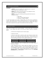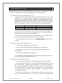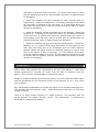
1
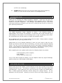
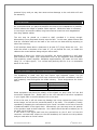
---------------------------------------------------------------------------
SYMPHONY POWER AMPLIFIER
OWNER’S MANUAL
-------------------------------------------------------------------------------
© Viola Audio La boratories 2004, 2005
The information contained in the manual is subject to change without notice. The
most current version of this manual will be posted on our web site at
www.Viola labs.com.
P/N: 91-symphonymanual
Revision: 01
TABLE OF CONTENTS
•
Safety Instructions
3
•
Introduction
4
•
Unpacking
4
•
Voltage Setting
4
•
Location
5
•
XLR Connector Pin Assignment
5
•
Speaker Cable Connection
6
o
Cables and Connectors
6
o
Single Speaker Cable Connection
6
o
Bi-Wire Connection
7
o
Bridge Connection
8
•
Bi-amplification
•
AC Power Cable Connection
10
•
Switching on for the First Time
10
•
Breaking In
10
•
Care and Cleaning
11
•
Fuses
11
•
Troubleshooting
12
•
Warranty
13
•
Service
14
•
Contacting VIOLA
14
•
Specifications
16
Viola Symphony Manual Rev 1
9
2 of 15
9 th September 2005
IMPORTANT SAFETY INSTRUCTIONS
Please read all of the following instructions carefully before operating your power
amplifier.
1.
The VIOLA Symphony weighs approximately 120lbs (54kg). NEVE R
try to move it on your own. Always use two people to move or
unpack the unit.
Take care to lift using your legs and avoid
straining your back.
2.
This product contains no user serviceable parts. NEVER attempt to
repair the unit yourself. Refer all servicing to a VIOLA approved
technician.
3.
This product must be connected to the mains supply with a threeconductor AC mains power cord that includes a ground connection.
To prevent shock hazard, all three connections must ALWAYS be
used. NEVER defeat the ground connection.
4.
ALWAYS disconnect your entire system from the AC mains before
connecting or dis connecting any cables, or when cleaning any
component.
5.
NEVER operate this unit with any covers removed. Dangerous
voltages may exist within the unit even when it is disconnected from
the mains supply.
6.
We do not recommend the use AC extension cords with this product.
If it is necessary to use an extension cord, please ensure that it
meets safety standards in your country and has sufficient current
capacity. (100V to 120V – 15A minimum, 220V to 240V 10A
minimum).
7.
NEVER use flammable chemicals for cleaning this product.
8.
NEVER wet the inside of this product with any liquid, or operate the
unit in a wet environment.
8.
NEVER block airflow through the ventilation slots on either the top
or the bottom of the unit.
9.
NEVER bypass any fuses.
10.
NEVER replace any fuse with a value or type other than those
specified. Suitable replacements are available from your local VIOLA
dealer, national distributor or directly from VIOLA.
11.
NEVER expose this product to temperatures outside the range 0°C
Viola Symphony Manual Rev 1
3 of 15
9 th September 2005
to 55°C non-condensing.
12.
ALWAYS disconnect the unit from the mains supply during lightning
storms , or if the unit will not be used for a prolonged period.
INTRODUCTION
TRODUCTION
Thank you for choosing the VIOLA Symphony Amplifier. Great care has gone into
the design and manufacture of the Symphony and if properly used, it will give a
lifetime of musical enjoyment.
We strongly recommend that you read these
instructions before you attempt to use the unit, so that you can be sure it is set up to
give optimum performance.
UNPACKING
The VIOLA Symphony Power Amplifier is heavy - the shipping weight is
approximately 120 pounds (55 kilograms). To avoid the risk of both personal injury
and damage to the product, do not attempt to lift it from its packing carton alone.
We recommend you use two people to unpack this amplifier safely.
Never attempt to lift the unit while bending from the waist. Always stand as straight
as possible and use your leg muscles to lift.
Please keep all of the packing materials in case you ever need to ship the unit.
Should you need to return the unit to the factory, you must use the original, shipping
carton. The use of any ot her packing may result in the product sustaining damage in
transit. Such damage is not covered by the warranty. Replacement shipping cartons
may be obtained via your VIOLA dealer, or directly from the factory.
After unpacking the unit, please confirm that the following items are present:
1 Viola Symphony power amplifier
1 user manual
1 three-conductor mains cord
If any of the above items are missing, or if the amplifier shows any signs of damage,
please contact your VIOLA dealer imme diately.
VOLTAGE SETTING
Before going any further please, confirm that the unit is set to operate on the mains
voltage you plan to use. The setting is marked on the unit’s rear panel above the
right hand fuse. If the setting on your unit is not correct, contact your VIOLA dealer.
Only a VIOLA approved technician should change the voltage setting. Do not
attempt to do this yourself. Should you set the unit to the wrong voltage, you risk
Viola Symphony Manual Rev 1
4 of 15
9 th September 2005
personal injury and you may also cause serious damage to the unit which will void
the warranty.
LOCATION
We recommend that you place the amplifier as close to the loudspeakers as possible,
as this reduces the length of speaker cable required. Whilst this make it necessary
to use longer interconnect cables, long interconnects cause less sonic degradation
than long speaker cables.
The unit may be placed on a stand or shelf, provided it is strong enough.
Alternatively it may be placed directly onto the floor. In this case, please ensure that
that the ventilation slots on the base of the unit are not obstructed by carpeting or
other floor covering.
In all locations please allow a clearance of at least 3.5” (5cm) above the unit. You
must also allow a clearance of at least 6” (15 cm) behind the unit, to enable the
cables to be routed without being subject undue strain.
Regardless of where you locate your amplifier, we advise positioning it well away
from sensitive low signal level components such as pre-amplifiers and turntables.
The Symphony power amplifier dissipates approximately 225 watts as heat when
idling (i.e. no input signal). It is normal and perfectly safe for it to run somewhat
warm to the touch.
XLR CONNECTOR PIN ASSIGNMENT
The Symphony is fitted with XLR and Fischer type balanced inputs. The pin
assignments of the Symphony’s XLR input conforms to the AES 14 standard, which is
now commonly used throughout the audio industry. These assignments are shown
below:
Pin 1:
Pin 2:
Pin 3:
Connector shell:
Signal ground
Signal + (non-inverting)
Signal - (inverting)
Chassis ground
Some equipment may have the polarity of the signals on pins 2 and 3 of the XLR
connectors swapped over. Please refer to the user manuals of the other equipment
in your signal chain to confirm whether this is the case.
If this is the case, it will not cause any damage, but it may reduce the quality of the
stereo image, as well as the perceived attack of the bass. This situation is easily
remedied by swapping the connections of pins 2 and 3 at either end of one of one set
of balanced cables in the signal chain. Alternatively you can swap over the polarity
of the speaker leads on both channels. Your dealer should be able to advise you on
the best course of action.
If two items in the signal path have the connections to pins 2 and 3 of the XLR
connector reversed with respect to the AES standard, this cancels out the problem
and you need take no further action.
Viola Symphony Manual Rev 1
5 of 15
9 th September 2005
SPEAKER CABLE CONNECTION
Caution!
• NEVER connect a power amplifier's output terminals to any
device other than a loudspeaker.
• NEVER short-circuit the amplifier's output terminals.
• ALWAYS switch the amplifie r off before connecting or
disconnecting signal or speaker cables.
CABLES AND CONNECTORS
To realize the full potential of the Symphony, we recommend the use of a highquality speaker cable such as the VIOLA Jazz cable. Please consult your VIOLA
dealer for details.
The Symphony is equipped with two pairs of high quality binding posts on each
channel. These are designed to accept cables fitted with spade lugs. The lugs
should be either soldered or crimped to the speaker cable – the latter is preferred.
We do not recommend the use of bare wire to connect the speaker cable to the
binding post. This produces an inferior connection that degrades with time as the
bare conductors become tarnished.
SINGLE SPEAKER CABLE CONNECTION
In this case you will only use one pair of binding posts on each channel of the
amplifier.
Starting with the left channel, connect upper or lower red binding post on the rear of
the Symphony (which ever is convenient) to the input terminal marked +, or colored
red on the left speaker.
Connect the adjacent black binding post on the rear of the Symphony to the input
terminal marked -, or colored black on the left speaker.
Repeat the process for the right channel of the amplifier and the right speaker.
The connection for one channel is shown in figure 1 below.
Viola Symphony Manual Rev 1
6 of 15
9 th September 2005
Speaker
Symphony
RED
BLACK
H
L
H
L
L
H
-
+
Figure 1. Single speaker cable connection.
BI-WIRE CONNECTION
Bi-wireable speakers have separate inputs for the high frequency (HF) and low
frequency (LF) sections of their cross-overs and these are connected to the power
amplifier with separate speaker cables. This form of connection is regarded as
superior to single wiring, as it avoids interactions between the low and high
frequencies that may occur when a single speaker cable is used. In this case you will
use both pairs of binding posts on each channel of the amplifier. You will also
require two sets of speaker cables.
Starting with the left channel, connect lower red binding post on the rear of the
Symphony to the input terminal marked +, or colored red on the left speaker’s LF
input.
Connect the lower black binding post on the rear of the Symphony to the input
terminal marked -, or colored black on the left speaker’s LF input.
Connect upper red binding post on the rear of the Symphony to the input terminal
marked +, or colored red on the left speaker’s HF input.
Connect the upper black binding post on the rear of the Symphony to the input
terminal marked -, or colored black on the left speaker’s HF input.
Repeat the process for the right channel of the amplifier and the right speaker.
The connection for one channel is shown in figure 2 below.
Viola Symphony Manual Rev 1
7 of 15
9 th September 2005
Speaker
Symphony
RED
BLACK
H
L
H
L
L
H
-
+
-
+
Figure 2. Bi-wire connection.
Note: Bi-wireable speakers are often shipped with links between the inputs to the
two sections of the cross-over. Ensure that these links are removed, or the benefits
of bi-wiring will not be realized.
BRIDGE CONNECTION
The two channels of the Symphony may be connected in what is called “Bridge
Connection” to form a mono amplifier that can deliver approximately 4 times the
output power of the individual channels. This allows the Symphony to be converted
from a stereo power amplifier that can deliver 200W per channel into 8 ohms, into a
mono power amplifier that can deliver 800W into 8 ohms.
This works by feeding the input signal directly into one channel whilst feeding an
anti-phase version of the same signal to the input of the other channel. The speaker
is connected between the High terminals of the two outputs.
Producing the anti-phase signal for the second channel is easy as the input
connectors of each channel are wired in parallel. It simply involves connecting a
cable from the unused input connector of the first channel to either input of the
second channel. The anti-phase signal is produced by wiring the cable so that the
connection between pins 2 and 3 either connector on this cable are swapped over.
Suitable cables may be obtained from your VIOLA dealer, or directly from VIOLA.
The following instructions are for the most common case where the main input is
connected to the XLR input of the first channel.
Viola Symphony Manual Rev 1
8 of 15
9 th September 2005
Connect the bridging cable between the Fischer input connector on the right channel
and the XLR input connector on the left channel.
Connect right channel upper or lower red binding post on the rear of the Symphony
(which ever is convenient) to the input terminal marked +, or colored red on the
speaker.
Connect left channel upper or lower red binding post on the rear of the Symphony
(which ever is convenient) to the input terminal marked -, or colored black on the
speaker.
These connections are shown in figure 3 below.
Speaker
Signal In
Symphony
BRIDGING CABLE
RED
BLACK
H
L
L
L
L
H
-
+
Figure 3. Bridge mode connection.
BI-AMPLIFICATION
Bi-amplification uses two stereo amp lifiers to power a single pair of loudspeakers.
One amplifier is used for each loudspeaker, with one channel driving the L.F. unit
and the other the mid/H.F. unit. Bi-amplification reduces the interaction not only
between the upper and lower frequencies, but also between the left and right
channels.
Viola Symphony Manual Rev 1
9 of 15
9 th September 2005
AC POWER CABLE CONNECTION
If the wall outlet you plan to use for the Symphony has an on/off switch, check that
it is switched off.
Insert the supplied AC mains cord into the receptacle on the rear of the Symphony
and ensure that it is pushed securely home.
Insert the other end of the mains cable securely into the mains outlet. Take care to
arrange the cable so that it is not bent sharply and that its weight will not pull it out
of either the mains outlet, or the receptacle on the rear of the Symphony.
Do not switch the unit on yet.
SWITCHING ON FOR THE FIRST TIME
Check that all the signal cables in the system are correctly connected.
Select the appropriate input on the pre-amplifier and set the volume to minimum.
Switch on the pre-amplifier and your signal source. We will assume is a CD player.
Allow the system to stabilize for 2 minutes, then put a CD into the player and press
play.
If the wall outlet you are using for the Symphony is switchable, switch it on now.
Press the power switch on the front panel. When the unit starts, this will glow green.
Allow the unit to stabilize for 2 minutes, then slowly increase the volume on the preamplifier to a comfortable level. The unit is now ready for use.
If you experience any problems, please refer to the TROUBLE SHOOTING section of
this manual.
BREAKING IN
Although your VIOLA Symphony power amplifier will deliver outstanding performance
straight out of the box, you may expect to hear it continue to improve as it reaches
its normal operating temperature and its various components "break-in." It has been
our experience that the greatest changes occur within the first 25-50 hours. The
amplifier will continue to improve in sound quality for about 300 hours from the start
of use.
The only exception to this rule is if the unit is switched off, allowing it to cool down.
In this case, a brief warm-up period will be required before the amplifier's sound
quality reaches its best. It is not necessary to repeat the initial 300 hour break-in.
Viola Symphony Manual Rev 1
10 of 15
9 th September 2005
CARE AND CLEANING
Caution!
• ALWAYS switch the amplifier off and disconnect it from the
mains supply before attempting to clean it.
• NEVER apply cleaning products directly to the amplifier as they
may enter the unit and cause damage.
• NEVER use any of the following cleaning products as they may
damage the finish:
• Wax polish
• Spirit or alcohol based cleaners
• Corrosive or abrasive cleaners
In most cases wiping the unit with a slightly damp soft cloth will give satisfactory
results. Non-abrasive glass cleaners containing ammonia or vinegar, applied with a
soft cloth may also be used. If you have concerns about the suitably of a cleaner,
first it out on a part of the unit that is less visible such as the rear panel.
MAINS FUSES
Two fuses are located on the unit’s rear panel – one for each side of the mains
supply. If you suspect that either of the fuses has blown, follow the procedure
below:
• Disconnect the amplifier from the mains supply.
• Remove the fuses.
• Check the fuses with a continuity tester and replace any blown fuses
with one of the rating and type shown below. Using a fuse of the
incorrect type or rating may create a safety hazard or cause damage to
the unit and may also result in the warranty being voided.
Operating Voltage
100V, 110V or 120V
220V or 240V
Fuse Rating
T15A
T10A
Fuse Size
1 1/4 inch
5 x 20mm
Suitable replacements may be obtained from your VIOLA dealer or
directly from VIOLA.
• After replacing the fuse or fuses, switch the amplifier on and check
whether it operates normally. If the fuses blow again, switch the unit
off immediately, disconnect it from the mains supply and get in touch
with your VIOLA dealer, national VIOLA distributor or VIOLA directly for
technical support. Contact details for VIOLA are given in the GETTING
IN TOUCH section of this manual.
Viola Symphony Manual Rev 1
11 of 15
9 th September 2005
TROUBLE SHOOTING
Most problems may be resolved by following the steps below. If these fail, please
contact your VIOLA dealer, national VIOLA distributor or VIOLA directly.
1.
No sound and the front panel LED is not lit?
• Press the front panel power switch to confirm that the unit is not
switched off. If there has been a temporary interruption to the mains
supply, or the supply voltage has dropped below certain limits, the unit
will automatically shut down and cannot be restarted until the mains
voltage returns within the normal operating range. The drop-out voltage
and normal operating range for 120V and 240V units are shown below.
Mains Setting
120V
240V
Drop Out Voltage
90V
180V
Normal Operating Range
90V – 140V
180V – 280V
• Check that the power lead is fully home in the AC input receptacle on
the rear panel, the other end is plugged into the AC wall socket and if
applicable, that the wall socket is switched on.
• Check that there is power on the AC wall socket by connecting another
piece of equipment that is known to work to the socket.
• Check the mains fuses as shown in the MAINS FUSES section of this
manual.
2.
No sound and the front panel LED is lit?
•
Check all the signal wiring in the system.
•
Check that all the units feeding the amplifier are switched on.
• Check that any input selector and other relevant switches are set
appropriately.
•
Check that the signal source is playing.
• Check that the pre-amplifier and or signal source volume control(s) are
set at a level that is loud enough to hear.
3. The amplifier keeps shutting down?
•
Disconnect the inputs to both channels and also the speaker cables.
• Try to switch the amplifier on. If it starts but then shuts down, contact
your VIOLA dealer, national VIOLA distributor or VIOLA for assistance.
If it starts (front panel LED comes on) and it stays on, there is either a
fault with the signal source such as a DC voltage on one or both channels,
or a short circuit in the speaker cables or speaker. This may be isolated
in the following steps.
• Switch the amplifier off and reconnect one channel from the signal
source. Switch the amplifier on. If it starts (front panel LED comes on)
Viola Symphony Manual Rev 1
12 of 15
9 th September 2005
and stays on proceed to the next step. If it shuts down there is a fault
with the signal source and you should contact the dealer or maker directly
for assistance.
• Switch the amplifier off and reconnect the other channel from the
signal source. Switch the amplifier on. If it starts (front panel LED comes
on) and stays on proceed to the next step. If it shuts down there is a
fault with the signal source and you should contact the dealer or maker
directly for assistance.
• Switch the amplifier off and reconnect one of the speakers. Switch the
amplifier on. If it starts (front panel LED comes on) and stays on proceed
to the next step. If it shuts down check the speaker cables for a short. If
these appear to be OK there may be a fault with the speaker and you
should contact the dealer or maker directly for assistance.
• Switch the amplifier off and reconnect the other speaker. Switch the
amplifier on. If it starts (front panel LED comes on) and stays on, the
fault was most likely due to an intermittent short on either channel’s
speaker cables and these should be inspected carefully to ensure that
there is no danger of this re-occurring. If it the amplifier shuts down
check the speaker cables for a short. If these appear to be OK there may
be a fault with the speaker and you should contact the dealer or maker
directly for assistance.
WARRANTY
VIOLA Audio Labs products are warranted to be free from defects if used under
normal conditions for a period of 5 years from the date of shipment from the
factory. This warranty is transferable to subsequent owners.
Repairs or modifications carried out by the factory, or by an authorized repair agent,
shall be guaranteed for the remaining portion of the warranty, or for 1 year, which
ever is greater.
Any unauthorized modifications or repairs will result in the warranty becoming void.
The warranty will also become void if VIOLA determines that the unit has been
subject to misuse.
There is no other express warranty on VIOLA products. This warranty shall not
extend beyond the stated warranty period. No responsibility is assumed for
incidental or consequential damage.
Viola Symphony Manual Rev 1
13 of 15
9 th September 2005
SERVICE
Customers Within the USA
In the first instance please contact your local VIOLA dealer. Should they be unable
to assist you, please contact VIOLA by phone on 1-203-772-0435, by fax on 1-203772-0569, or by email at service@Viola labs.com. Please supply as much information
about the problem as possible, including the unit’s serial number and details of all
equipment in the system when the fault occurs.
If it becomes necessary to return your unit to the factory, you will be given a Return
Authorization (RA) number. This number must be clearly marked on the outside of
the shipping box. Returns without a RA number will not be accepted. Returns
received in non-standard packing will be replaced with new packing at the owner's
expense. If you need new packing, please contact your VIOLA dealer or the factory.
For units returned to the factory under warranty during the first year, VIOLA will pay
for the freight charges both ways. A VIOLA approved shipping company must be
used and the units will be returned to the customer using the same carrier, or an
equivalent servic e.
For units returned to the factory under warranty during years 2 to 5, the customer is
responsible for paying the shipping charges back to the factory. A VIOLA approved
shipping company must be used. Providing this condition is met, VIOLA will pay the
cost of shipping the units back to the customer.
VIOLA will not pay freight costs if units are returned without a RA number, or if no
fault is found. Customers are responsible for all freight charges for units returned for
non-warranty repairs.
Customers Overseas
Please contact your local VIOLA dealer, or the official VIOLA distributor in your
country. If they are unable to assist you, please contact VIOLA by phone on 1-203772-0435, by fax on 1-203-772-0569, or by email at service@Viola labs.com. Please
supply as much information about the problem as possible, including the unit’s serial
number and details of all equipment in the system when the fault occurs. Should it
become necessary for you to return your unit to VIOLA directly, the same conditions
as apply for US customers must be observed regarding freight charges and obtaining
Return Authorization numbers.
CONTACTING VIOLA
Should you need to contact VIOLA, please note that our office hours are 8 a.m. to 4
p.m. EST and that we cannot respond to telephone enquiries outside of these hours.
Address
Telephone
Fax
Email
Viola Symphony Manual Rev 1
315 Peck Street
New Haven, CT 06513
USA
1 203 772 0435
1 203 772 0569
[email protected]
14 of 15
9 th September 2005
SPECIFICATIONS
Class of Output Operation: AB2
Power Rating:
200W continuous average power into 8 ohms
20Hz to 20kHz, both channels driven at less than 0.25% THD
400W continuous average power into 4 ohms
20Hz to 20kHz, both channels driven at less than 0.5% THD
IM Distortion (SMPTE):
1W to 200W into 8 ohms <0.075%
1W to 400Winto 4 ohms <0.10%
THD:
<0.1% @ 20 kHz/200 watts
Frequency Response:
1W into 8 ohms (10Hz - 20kHz) +/-0.15 db; 100k <-3 db
Power Bandwidth:
5 Hz to 100 kHz (-3dB points)
SN Ratio:
-105 db at 1 kHz / 200W; C weighted
Gain:
26 dB
Input Impedance:
1M Ohm / 1M Ohm balanced
Inputs:
Balanced - XLR and Fischer
Output Connections:
Binding post for spade terminals
Power Consumption:
Approximately 225W at idle. 1800W maximum
Weight:
Amp lifier:
Packed:
Dimensions:
Height including feet:
Width:
Depth including binding posts:
120 lbs. (55 kg)
127 lbs. (57 kg)
8 5/8”. (21.9cm)
17 5/8”. (44.8cm)
19”. (48.3c m)
Specifications are subject to change without notice.
Viola Symphony Manual Rev 1
15 of 15
9 th September 2005