1
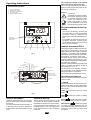
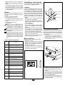
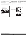
DPC-1
Ref: N-40130 0404M
E
Termostato digital programable con comunicación
Instrucciones de Manejo y mantenimiento
○
○
○
○
○
○
○
○
○
○
○
○
○
○
○
○
○
○
○
○
○
○
○
○
○
○
○
○
○
○
○
○
○
○
○
○
○
3-8
GB Programmable digital thermostat with communication
Operating and Maintenance Instructions
F
○
○
○
○
○
○
○
○
○
○
○
○
○
○
○
○
○
○
○
○
○
○
○
○
○
○
○
○
○
○
○
○
○
9 - 14
○
○
○
○
○
○
○
○
○
○
○
○
○
○
○
○
○
○
○
○
○
○
○
○
○
○
○
○
○
○
○
○
○
○
○
○
○
○
○
○
○
○
○
○
○
○
○
○
○
○
○
○
○
○
○
○
○
○
○
○
○
15 - 20
○
○
○
○
○
○
○
○
○
○
○
○
○
○
○
○
○
○
○
○
○
○
21 - 26
Termostato digitale programmabile con comunicazione
Istruzioni per l'uso e la Manutenzione
D
○
Termóstato digital programável com comunicação
Instruções de Utilização e Manutenção
I
○
Thermostat digital programmable avec communication
Instructions d'Utilisation et de Maintenance
P
○
○
○
○
○
○
○
○
○
○
○
○
○
○
○
○
○
○
○
○
○
○
○
○
○
○
○
○
27 - 32
Programmierbarer Digital-Thermostat mit Kommunikationsmöglichkeit
Hinweise zu Bedienung und Wartung
○
○
○
○
○
○
○
○
○
○
○
○
○
○
○
○
○
○
○
○
○
○
○
○
○
○
○
○
○
○
○
○
○
○
○
○
○
○
33 - 38
NL Programmeerbare digitale thermostaat met communicatieverbinding
Bedienings- en onderhoudsinstructies
N
○
○
○
○
○
○
○
○
○
○
○
○
○
○
○
○
○
○
○
○
○
○
○
○
○
○
○
○
○
○
○
○
○
○
○
○
○
○
○
○
○
○
○
○
○
○
○
○
○
○
39 - 44
Programmerbar digital termostat med kommunikasjon
Betjenings- og vedlikeholdsinstrukser
○
○
○
○
○
○
○
○
○
○
○
○
○
○
○
○
○
○
○
○
○
○
○
○
○
○
45 - 50
E U R O V E N T
ER-0028/1991
ISO 14001
ISO 9001
CERTIFIED PERFORMANCE
CGM-97/013
Clima Roca York S.L. participa en el Programa de Certificación EUROVENT.
Los productos se corresponden con los relacionados en el Directorio EUROVENT de
Productos Certificados, en el programa AC1, AC2 y AC3.
Clima Roca York S.L. partecipa al Programma di Certificazione EUROVENT.
I prodotti interessati figurano nella Guida EUROVENT dei Prodotti Certificati, nel
programma AC1, AC2 e AC3.
Clima Roca York S.L. is participating in the EUROVENT Certification Program.
Products are as listed in the EUROVENT Directory of Certified Products, in the program
AC1, AC2 and AC3.
Clima Roca York, S.L. ist am Zertifikationsprogramm EUROVENT beteiligt.
Die entsprechend gekennzeichneten Produkte sind im EUROVENT-Jahrbuch im Programm
AC1, AC2 und AC3 enthalten.
Clima Roca York S.L. participe au Programme de Certification EUROVENT.
Les produits figurent dans l'Annuaire EUROVENT des Produits Certifiés, dans le
programme AC1, AC2 et AC3.
Clima Roca York, S.L. neemt deel aan het EUROVENT-certificatieprogramma.
De produkten zijn opgenomen in het EUROVENT-jaarboek van de gecertificeerde
produkten, in de programma AC1, AC2 en AC3.
Clima Roca York S.L. participa no Programa de Certificação EUROVENT.
Os produtos correspondem aos referidos no Directório EUROVENT de Produtos
Certificados, no programa AC1, AC2 e AC3.
Clima Roca York, S.L. deltar i EUROVENT sertifiseringsprogram.
Produktene er oppført i EUROVENT's katalog over sertifiserte produkt, i kategorie AC1,
AC2 og AC3.
1
2
The compressor should not be started
until a minimum of eight hours later.
This is done to evaporate any refrigerant in
liquid form that may be been mixed in with
the oil in the compressor.
Operating instructions
Controls and indicators
1.2.3.4.5.-
Program mode selection.
Operating mode selection.
Day/night/unoccupied selection.
Fan speed selection
Outdoor temperature reading
Caution:
POWER
SUPPLY
ON
AUTO
PROG
Recommendations for best operation
AUTO
°C
4
0h 2
4
6
- Turn the air conditioning on before the
room gets warm. Any heat accumulated
on furniture, walls, etc., makes the unit
take longer to reach the desired temperature.
- It is advisable to inspect and service your
equipment whenever necessary; this
avoids damage and ensures long service
life of your air conditioner.
8 10 12 14 16 18 20 22 24
SET POINT
TEMPERATURE
SELECTION
PROG
Connection:
To preheat the system, the electrical heater should be tourned
on at least 8 hours prior to starting the air conditioning unit.
Leave power supply on, unless
the air conditioner is not to be
used during long periods of time.
MODE
Ambient thermostat DPC-1
1
2
3
Keyboard locked
These thermostats are designed to give precise ambient temperature control and
graphic information with regard to heat pump
operation. In compliance with the differential between the programmed and ambient
temperatures, it varies the on/off cycles.
The liquid crystal display (LCD) normally
shows the ambient temperature, the operating mode and whether the cooling or heating system is in operation.
It allows selecting different temperature set
points for cooling and heating, as well as
their indication in °C or °F.
The fan can be set to operate in a continuous or automatic mode, stopping and operating jointly with the compressor..
The controls are located beneath a cover.
Failure or incident
Outdoor temperature
Operation and start-up
Dirty filters
Start-up is carried out by means of the thermostat controls.
4
5
Fig. 1
Cooling
Heating
Timer
active
Unoccupied
Temperature
setting
Economy (night)
Room temperature
Comfort (day)
Air conditioning
mode
Fan
OFF
EMERG
HEAT
COOL
AUTO
PROG
Dead battery
°F
AUTO
°C
1 2 3 4 5 6 7
Day of
the week
0h 2
4
6
8
10 12 14 16 18 20 22 24
1.- MODE
Time
Pressing this button sets the heat pump operating mode. When pressed alternatively,
the LCD screen shows the following operating modes:
Time schedule profile
Fig. 2
General information
Important warning
Automatic temperature start-up and regulation is carried out by means of an ambient
thermostat.
Locate the thermostat at approximately 1.5
m. above floor level, where no obstacle can
avoid measuring the real temperature of the
room.
The thermostat should be placed on a wall
not exposed to direct sunlight; otherwise,
temperatures would not be real and operation would be poor. Before starting up, turn
the general switch on so as to supply power
to the electrical heater of the compressor
crankcase.
GB
COOL
mode.
Controls the system in cooling
HEAT
mode.
Controls the system in heating
AUTO
Controls the system in either
the cooling or heating modes, as needed.
AUTO PROG.
Controls the system
in cooling or heating, depending upon the
time schedule profile selected. (If microswitch pin 2 is set to OFF, this option does
not appear.
9
EMERG HEAT. Controls the system in emergency heating mode (operates only if an
electric heater, optional accessory, is installed).
OFF. Turns the air conditioning system off
or could be use to set fan only mode.
a) Cooling
Press MODE button alternatively until
appears on the
the cool symbol
screen (along with the word COOL)
(Fig. 3).
AMBIENT TEMPERATURE
MODE SELECTED
COOL
AUTO
°C
5
c) Automatic
Press the MODE button alternatively
until the heating
and cooling
symbols appear on the screen (along with
the word AUTO) (Fig. 5).
Select a temperature setting for the cooling mode and another for the heating
mode as desribed in paragraphs a) and
b). In this operating mode, the COOL
temperature setting should be least 1°C
above the HEAT temperature setting,
which is the minimum differential allowed by the thermostat. Press the MODE
button repeatedly displays the cooling
or heating set points. After 5 seconds
the ambient temperature is displayed
(Fig. 5).
COOLING SYMBOL
Fig. 3
MODE SELECTED
HEATING SYMBOL
Once the operating mode is set, select
the temperature setting by pressing
button
or
so as to set a higher
or lower temperature. The temperature
seting appears along with a small symbol that represents a thermometer, and
remains on screen for 5 seconds. When
the temperature setting disappears, the
ambient temperature appears once
again.
After a few minutes, the cooling system
will begin to operate and the cooling
symbol on screen will start to flash.
b) Heating
Press the MODE button alternatively
until the heating
symbol appears on
the screen (along with the word HEAT)
(Fig. 4).
AMBIENT TEMPERATURE
MODE SELECTED
HEAT
AUTO
°C
5
For correct operation of this mode, first
you must set the time on the clock and
select the number of the day of the week.
Then select the desired time schedule
profile for the different days of the week.
See the section on Programming Menu.
Select a temperature setting for the cooling mode and another for the heating
mode, in accordance with the programming menu. (Fig. 6)
In this mode you must define the temperature set point for day, night and unoccupied conditions.
After a few minutes, the system will start,
switching automatically to either the heat
or cool mode and keeping the ambient
temperature between the selected set
points and in compliance with the time
schedule profile selected.
ambient temperature appears once
again.
After a few minutes, the heating system
will begin to operate and the heating
symbol on screen will start to flash.
AMBIENT TEMPERATURE
AUTO
AUTO
°C
1
e) Emergency heat
Press the MODE button alternatively
until the words EMERG HEAT are displayed, along with the heating
symbol. After a few minutes, the emergency
heat will begin to operate and the heating symbol
will flash on the screen.
In this operating mode, the compressor
is always inoperative and the auxiliary
and emergency heaters (optional accessories), if installed, are used for heating.
This operating mode can be used for
heating when there is any problem with
the compressor (Fig. 7).
COOLING SYMBOL
Fig. 5
After a few minutes, the system will
beging to operate, switching automatically between the heating and cooling
modes so as to keep the ambient temperature between the two settings.
When either the heating or cooling
mode are in operation, the corresponding symbol starts to flash.
AMBIENT TEMPERATURE
MODE SELECTED
EMERG
HEAT
d) Automatic programming
If this option is not selected, it will not
appear (can be selected by setting micro-switch No. 2 to ON). Press the
MODE button alternatively until the heating
and cooling
symbols are displayed (along with the words AUTO
PROG). The selected time schedule profile is also displayed (Fig. 6).
AUTO
°C
5
HEATING SYMBOL
Fig. 7
HEATING SYMBOL
Fig. 4
Once the operating mode is set, select
the temperature setting by pressing butor
so as to set a higher or
ton
lower temperature. The temperature
setting appears along with a small symbol that represents a thermometer, and
remains on screen for 5 seconds. When
the temperature setting disappears, the
10
AUTO
PROG
AUTO
°C
1
DAY OF
THE WEEK
0h 2
4
6
8
10 12 14 16 18 20 22 24
TIME
TIME SHCEDULE
PROFILE
COOLING SYMBOL
Fig. 6
GB
AMBIENT TEMPERATURE
HEATING SYMBOL
MODE SELECTED
COMFORT (DAY)
COMFORT (DAY)
ECONOMY (NIGHT)
f) Off
Press the MODE button alternatively until OFF appears on the screen. The unit
is turned off and the word OFF, the ambient temperature, the day of the week
and the time are displayed permanently
on the thermostat display (Fig. 8).
ating modes).
Once the thermostat is installed, the
symbol is displayed, indicating that the temperature settings selected is for the day
period (comfort). Pressing the
button displays the
symbol, indicating that
the temperature settings is for the night period.
Whenever this button is pressed the temperature settings are alternated, in both day
and night
periods.
OFF
°C
3
DISPLAY WHEN THE UNIT
IS FULLY OFF
Fig. 8
g) Ventilation only
This operating mode is available in the
OFF mode by pressing the
button, which selects the fan speed.
OFF
°C
3
h) °C/°F scale
To change the temperature degree
scale, press the
buttons simultaneously.
2.- Fan
When the
button is pressed, the Adjust mode is entered for 5 seconds. The fan
symbol
is flashing. Pressing de
button, you adjust the fan speeds ( ) and
the fan regulation: automatic (AUTO) or in
continuous operation (AUTO disappear).
When the fan is set automatic (AUTO), it
will operate automatically the fan in
acordance with the compressor or heating
sources. Example:
-
AUTO
Automatic high speed
Fixed low speed
- You can configurate the thermostat with
only one speed (micro-switch nº 6 to ON)
3.- Day/night selection
By pressing the
button you can select different temperature settings for the day
and night periods (in each one of the oper-
4.- Unoccupied selection
Pressing the
button for over 1 second selects the unoccupied temperature
setting. Pressing the
or
button
selects the desired temperature. If the MODE
button is pressed in AUTO mode, the cool
or heat set points in unoccupied mode are
displayed alternatively.
If while in the adjust mode the PROG button is pressed, the temperature setting is
replaced by number 0, indicating the number
of days the unoccupied mode should last.
The
and
buttons increase and
decrease the number of unoccupied days.
If left at 0, this mode is maintained indefinitely; but if a number of days beyond 0 is
programmed, the
icon flashes throughout the unoccupied period, indicating its
temporary nature. Once the unoccupied
period has concluded, the thermostat will
switch over to the day period (confort), except when the air conditioning mode is
AUTO PROG, in which case the occupation mode will be the mode indicated by the
time schedule profile.
To exit the unoccupied option, just press the
button.
5.- Reading outdoor temperature
Pressing the
button displays the outdoor temperature for 5 seconds.
6.- Ambient temperature remote sensor
option
The DPC-1 thermostat is designed to accept a remote sensor for controlling the
ambient temperature of a room other than
the one the DPC-1 thermostat is located in.
The remote sensor is to be connected to
the inner connecting strip of the thermostat,
terminals RS1-RS2.
7.- Graphic information
The display provides constant information
on: ambient temperature, operating mode,
day/night period and fan operation. To have
acces to information on the temperature set
points press, just once, one of the temperature setting buttons. This will give us, on
screen and for 5 seconds, the temperature
set point established for the operating mode
that is visible on screen at that moment.
played on screen:
Clock setting (day of the week, hours
and minutes).
Fan setting.
Selection of schedule
profiles. A schedule profile accepts
only Comfort and Economy (Day and
Night) periods. If pin 2 of the microswitch is set to OFF, this option is
not displayed.
Select temperature setting for heating and cooling mode in Comfort
(Day) period.
Select temperature setting for heating or cooling mode in Economy
(Night) Mode.
Select temperature setting for heating and cooling in Unoccupied Mode.
The active or selectable option will flash.
The initial option is setting the clock.
0h 2
4
6
8
10 12 14 16 18 20 22 24
0h 2
4
6
8
10 12 14 16 18 20 22 24
The active buttons are:
Allow selecting the active option.
Allow changing the selection.
Selects the active option.
Exits the Programming menu ,
switching the thermostat in Normal
Mode.
The display will come back to Normal mode
if no button have been pushed during 30
seconds.
1- Clock setting
Allows setting the day of the week, hour and
minutes.
1
Programming menu
If the PROG button is pressed in Normal
Mode, only the symbols of the different parameters that can be programmed are dis-
GB
11
2- Fan setting
Allows programming fan status in the different occupation periods (Day, Night or Unoccupied). Periods and fan status are displayed.
4- Selection of time schedule profiles
There are five predetermined profiles (P1
to P5), and an additional
profile that
can be programmed by the user.
Upon selecting the
option on the programming menu, all days of
the week are displayed on screen, with day
1 of the week (Monday) flashing, the program presently memorized for this day,
flashing and the corresponding profile.
0h 2
4
6
8
10 12 14 16 18 20 22 24
Micro-switches for configuration of the thermostat
The thermostat has a configuration system
through micro-switches located in rear of the
front panel.
For standard thermostat operation, these
pins are factory-set to OFF. Nevertheless,
these settings can be change in accordance
to user needs. The functions of each one
are described below.
AUTO
"A"
REAR OF
FRONT
PANEL
1 2 3 4 5 6 7
0h 2
6
8
10 12 14 16 18 20 22 24
R
B
G
Y
Y2
W
O/B
X1
X2
RS2
RS1
DETAIL "A"
ON
The predetermined profiles are 5:
1. P1, always economy (night),
0h 2
4
6
8
1
2
3
4
5
6
MICRO-SWITCHES SW1
10 12 14 16 18 20 22 24
2. P2, always comfort (day),
0h 2
4
6
8
10 12 14 16 18 20 22 24
3. P3, with comfort cycle of 7-23 hours, the
rest economy (night),
0h
2
4
6
8 10 12 14 16 18 20 22 24
4. P4, with two comfort cycles of 7-9 and
18-23 hours, the rest economy (night),
0h 2
4
6
8
10 12 14 16 18 20 22 24
5. P5, with three comfort cycles of 7-9, 1315 and 18-23 hours, the rest economy
(night),
°C
0h 2
4
6
8
10 12 14 16 18 20 22 24
profile is displayed, the
When the user
text
appears in clock digits to indicate that the key with this denomination is
ready to program the profile.
Pressing the PROG key while displaying the
user
profile during Selection of time
schedule profiles accesses the configuration of this profile.
12
RS3
THERMOSTAT
BASE
AL
3- Day, Night or Unoccupied temperatures setting
There is a total of six programmable temperature settings that correspond to the heat
and cool modes of the three occupation
periodes (Day, Night and Unoccupied).
These settings must follow an order from
cooler (a) to warmer (f).
a. Cool set point in Unoccupied mode.
b. Cool set point in Night mode.
c. Cool set point in Day mode.
d. Heat set point in Day mode.
e. Heat set point in Night mode.
f. Heat set point in Unoccupied mode.
The thermostat will never allow differencial
of less than 1°C (2°F) between each setting. If when moving one of the setting we
come to less than 1°C (2°F) from the next
one, it will be “dragged” so as to avoid the
unsuitability of settings. When this occurs,
the thermostat will show it by flashing the
period icon of the setting being dragged.
4
GB
Micro-switches SW1 allow the configuration of the following parameters:
- Pin 1: Lock keyboard. In OFF the keyboard
is not locked. In ON the keyboard is locked
and the locked keyboard symbol ( ) is
displayed. The buttons that remain active
are:
,
and
(outdoor temperature reading).
- Pin 2: AUTO PROG mode activated. Defines whether the automatic air conditioning mode with time schedule programming (time schedule profiles) can be activated. OFF indicates the AUTO PROG
mode is deactivated, and ON indicates the
AUTO PROG mode can be selected.
- Pin 3: O/B signal: Set to OFF, heat is generated when the O/B (24 VAC) signal is
active, and cool when inactive. Set to ON,
cool is generated when the O/B (24 VAC)
signal is active, and heat when inactive.
- Pin 4: 2 minutes/4 minutes. Defines the
time between the end of one phase and
when it can be active again. OFF indicates
2 minutes, and ON, 4 minutes.
- Pin 5: Multi-stage. Defines single-stage
(one stage can be activated only) or multi-
stage (more than one can be activated).
OFF indicates single-stage and ON, multistage.
- Pin 6: Single-speed fan. Defines whether
the fan can operate at one or three
speeds. OFF indicates 3 speeds and ON,
1 speed. In single-speed, the wind icons
are not displayed.
Alarms
The alarm codes are displayed at the bottom left of the screen, overlapping hour and
minutes.
The alarm codes are as follows:
- 0-90, machine error codes.
- 91, temperature origin selected is invalid.
- 92, indoor temperature sensor not calibrated.
- 93, communication alarm.
- 94, alarm pin.
When an alarm is generated, the
wrench symbol is displayed. If the error
is machine or communication, this
symbol flashes; if not, it remains static.
Filters. If the dirty filters symbol is
displayed flashing, the filters need to
be changed.
Dead battery. The dead battery symbol
indicates the batteries are dead, and
these should be changed. System
configuration is not lost when changing
the batteries. Only day and time are
lost.
Table of lockouts (Red LED)
Code
Designation
11 / 21 / 31
Compressor discharge temperature
surpased or short circuited probe
12 / 22 / 32
High Pressure switch, outdoor fan overload
or compressor motor protection module
13 / 23 / 33
Low Pressure switch.
14 / 24 / 34
Indoor fan thermal switch
15 / 25 / 35
Repeated start-ups in cool, or suction temperature < -25°C
41
Gas 1 or electrical heater 1
42
Gas 2 or electrical heater 2
43
Electrical heater 3
44
Electrical heater 4
Installation instructions
It is recommended that the installation be
carried out by a qualified personal.
Location
To assure adequate operation, this thermostat should be installed on an indoor wall,
in a frequently occupied area of the building. Furthermore, it should be at at least 50
cms. from any outside wall, and at approximately 1.5 m. above floor level, in an area
with freely circulating air at average temperature. The following locations should be
avoided:
- Behind doors or in corners where freely
circulating air is unavailable.
- Where direct sunlight or radiant heat generated by other appliances may alter the
control operation.
- On an outside wall.
- Next to or in line with air conditioning discharge grids, stairwells or doors leading
outdoors.
- Where operation can be affected by steam
or water pipes, or hot air chimneys in adjacent areas or any other unheated/
uncooled area behind the thermostat.
- Where operation can be affected by the
supply air of any adjacent unit.
- Near sources of electrical interference,
such as arching relay contacts.
Basic elements
This thermostat comprises three parts:
- Hinged front cover.
- Front panel. This element contains the
operating and control keys, as well as the
printed circuit. Fastened to the base by
means of a plastic tab.
- The base. This box allows fastening the
thermostat to the wall, and contains the
electrical connecting strips.
46
Smoke detector, fire thermostat or air discharge temperature probe (rooftop only)
> 80° C
91
Selected probe not valid or short circuited
probe
92
Thermostat internal probe not calibrate
93
No communication between the thermostat
and the main PCB (YKlon)
94
Lockout from external input
FRONT COVER
FRONT PANEL
BASE
Thermostat installation
To fasten the thermostat to the wall, open
the front panel and uncover the base of the
thermostat. Proceed as shown in the following illustration:
1- Press the plastic tab at the base of the
thermostat, as indicated by arrow A.
2- While pressing A, raise the front panel
as indicated by arrow B.
FRONT PANEL
FRONT COVER
A
BASE OF THERMOSTAT
AUTO
°C
4
Economizer or hot water coil
ALKALINE BATTERIES
B
AUTO
45
ELECTRIC
CONNECTING
STRIP
0h 2
4
6
8
10 12 14 16 18 20 22 24
The fastening holes found at the base coincide with the standard electric boxes on
the market.
In the case the connecting cable does not
come from the electric box, the thermostat
must be fastened to the wall with the anchors and screws supplied.
Keep in mind that the rectangular hole in
the centre of the base is to house the electric connecting cable.
GB
13
Standard electric connections,
thermostat DPC-1 (for thermostat
with communication)
Once the base is fastened to the wall, wire
the thermostat as shown in the following illustration:
Caution
A shielded 10 x 0.22 mm² cable,
with a maximum length of 100 m.,
should be used between the thermostat and the control board.
Connections to be carried out are R, B and
X1. (The other 7 wires are necessary to
connect G, Y, Y2, O/B and W if you wish to
use a thermostat with relays)
To connect the remote sensor use shielded
2 x 0.5 mm2 cable with a maximum length
of 100 m. between the thermostat and the
sensor. The connections to be carried out
are RS1 and RS2.
For correct operation of the thermostat, it is
indispensable to have made electric wiring
properly, and have inserted the two AAA 1.5
V alkaline batteries at the rear of the front
panel, as shown below:
SHIELDED CABLE 2x 0,5 mm2 cable
(MAXIMUM LENGTH 100 m)
REAR OF
FRONT PANEL
SHIELDED 10x 0.22mm2 CABLE
(MAXIMUM LENGTH 100 m)
YELLOW
RED
B
AAA 1.5 V ALKALINE
BATTERIES
R
G
Y
Y2
W
O/B
X1
X2
RS1
RS3
RS2
AL
WHITE
BASE OF
THERMOSTAT
14
GB
R
G
B
Y
Y2
W
O/B
X1
X2
RS2
RS1
AL
Data and measurements are subject to change without prior notice.
RS3
BASE OF
THERMOSTAT
REMOTE PROBE
(OPTIONAL)
51
DECLARACION CE DE CONFORMIDAD SOBRE MAQUINAS
FABRICANTE:
CLIMA ROCA YORK, S.L.
DIRECCIÓN:
Paseo Espronceda, 278, 08204 SABADELL
Certificamos que el equipo descrito, es conforme a las exigencias básicas de las directivas Europeas que le son aplicables, incluidas las
modificaciones de las mismas y las correspondientes transposiciones a la ley nacional.
APLICACIÓN DE LA MÁQUINA:
TIPO:
AIRE ACONDICIONADO/REFRIGERACION
DPC-1
.........
DIRECTIVAS DE LA CE APLICADAS:
98/37/CEE, 73/23/CEE, 89/336/CEE
NORMAS ARMONIZADAS APLICADAS:
EN60204-1, EN292-1, EN292-2, EN563, EN294, EN953, EN55014,
EN60555-2, EN50082-1
NORMAS INTERNACIONALES Y
ESPECIFICACIONES TÉCNICAS APLICADAS:
LUGAR:
EN ISO 9001, EN ISO 14001
Sabadell, (España)
FIRMA:
ROMÁN LARRODA
JEFE CONTROL DE CALIDAD
DECLARATION OF COMPLIANCE ON MACHINERY
MANUFACTURER: CLIMA ROCA YORK, S.L.
ADDRESSE:
Paseo Espronceda, 278, 08.204 SABADELL
We hereby certify that the mentioned equipment complies with the essential requirements of the European directives applicable, including their
modifications and the corresponding transpositions from the national law.
APPLICATION OF THE MACHINE:
AIR CONDITIONER/COOLING
TYPE: .DPC-1
........
EEC DIRECTIVES APPLIED:
98/37/EEC, 73/23/EEC, 89/336/EEC
APPLIED HARMONIZED STANDARDS:
EN60204-1, EN292-1, EN292-2, EN563, EN294, EN953, EN55014,
EN60555-2, EN50082-1
APPLIED INTERNATIONAL TECHNICAL
STANDARDS AND SPECIFICATIONS:
PLACE:
Sabadell, (España)
EN ISO 9001, EN ISO 14001
SIGNATURES:
ROMÁN LARRODA
QUALITY CONTROL MANAGER
52