1
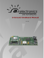
V 1.24
U-Ground OneBoard User Manual -
Table of Contents
1 General System Introduction..............................................................................................3
1.1 Concept of system operation......................................................................................4
2 U-Ground OneBoard...........................................................................................................5
3 Communications.................................................................................................................7
4 Joystick................................................................................................................................8
4.1 Connecting the Joystick to the Main connector..........................................................8
4.2 Configuration for Futaba Joystick...............................................................................9
Appendix AChangelog..........................................................................................................11
.............................................................................................................................................13
2
U-Ground OneBoard User Manual - General System Introduction
1 General System Introduction
Airelectronics has developed a complete solution for both rotary and fixed wing UAVs. The
system is composed of:
•
U-Pilot 0.2
•
U-Ground 0.2 or U-Ground OneBoard
•
U-See 0.2
U-Pilot takes care of the vehicle from Take-off to Landing. It is completely adaptable to any
aircraft including fixed wing, hexacopters, quadcopters and helicopters.
U-Pilot is completely capable of following a flight plan with up to 32 points (real time editable).
Once the flight plan is loaded on the U-Pilot it is independent of operator instructions. In case of
a failure in the communications, U-Pilot starts a Landing maneuver which would safely land the
UAV on the Runway Point.
Thanks to its versatility U-Pilot can control any device on board the UAV such as cameras,
parachutes and others. These devices can be real time controlled by a Computer Operator or
by U-Pilot automatically.
U-Pilot has, working in parallel:
•
15 PWM (Pulse-Width Modulation) outputs or even more if necessary,
•
3 ADC inputs (Analogical Digital Converter) to monitor the voltages of three batteries on
the UAV
•
4 serial ports RS232 to communicate with payloads, external magnetometers, etc.
•
A radio with up to 100 km1
•
GPS, dynamic and static pressure sensors, a magnetometer, gyroscopes and
accelerometers.
U-Pilot is built using a two parallel microprocessor approach:
•
One processor takes care of the state estimator and controls the UAV using hardware
acceleration to calculate high speed algorithms.
•
Another processor takes care of the mission at high level and the communications with
the U-Ground and Payloads management.
•
the processors do not waste any time doing low level tasks.
Due to the fact that those two processors are working in parallel and there is dedicated
electronics taking care of all the serial ports, sensors, inputs and outputs the system is capable
of recalculating its position, orientation and closing control loops at the speed of 1000 Hz. This
high speed gives the the UAV huge navigation accuracy and control.
On the ground segment, we have both U-Ground and U-See.
U-Ground is a control station with the other end of the radio link communicating the U-Pilot
with the U-See software.
U-See software is a user friendly program that runs in any personal computer running Windows,
Mac OS X or Linux.
Through U-See, the UAV operator can inspect the current state of the mission and command it
in real-time.
1 Range may vary with the frequency band used. Default is 900 MHz but legal limitations in some countries may
change this.
3
U-Ground OneBoard User Manual - General System Introduction
All the U-Pilot configuration is done by Airelectronics staff so the End User does not have to
waste any time setting the internal parameters of the system.
1.1 Concept of system operation
The system is made up of an U-Pilot installed on an aircraft connected to the U-Ground through
a radio link. (See figure 1 attached below)
The U-Ground has its own radio link to communicate with the U-Pilot. It also has an RS-232
output to relay the data to a PC running U-See to allow control from the End User.
A Futaba Joystick allows manual override and control.
Figure 1: System concept
The mission team usually is formed by two persons:
•
The External Pilot who will have the Futaba Joystick on its hands, in case a manual
control of the UAV is desired (specially during the development and adjustment phase).
•
The U-See operator that will command the mission using the PC.
4
U-Ground OneBoard User Manual - U-Ground OneBoard
2 U-Ground OneBoard
The U-Ground OneBoard hardware is the link between our U-Pilot and the computer running USee that finally controls the mission.
U-Ground OneBoard has an integrated GPS to track its own position and standard PWM outputs
to allow the steering of directional antennas towards the UAV to maintain a stable video link.
It also provides the manual override function, by connecting any standard Futaba transmitter
with a trainer port to the hardware. In that way, the external pilot can fly the UAV in a manual
mode (Refer to section 5, joystick) with the very familiar interface of a Futaba joystick, while
keeping all its functionality (exponential settings in control, mixtures, etc.)
The Futaba joystick must be connected to the ground hardware through its main connector
using a Futaba Training Cord provided with the Installation Kit.
Figure 2: Futaba Training Cord
The ground hardware relays the data it receives from the U-Pilot through a serial RS-232
interface. This data is processed in U-See running on a standard PC, which, obviously, should
have a RS-232 port available (We include a USB to RS-232 converter in the installation kit).
The connector used for the U-Ground OneBoard is supplied with the Installation Kit.
U-Ground OneBoard must be powered with a voltage between 6.0V and 8.4V.
The pin configuration is detailed in the following table.
5
U-Ground User Manual - U-Ground OneBoard
PIN
1
2
3
4
7
I/O
IN
OUT
IN
IN
IN
8
9
27
12
13
15
25
11
28
14
10
OUT
OUT
IN
OUT
OUT
OUT
OUT
OUT
OUT
OUT
OUT
GROUND HARDWARE
RS232 comms Rx
RS232 comms Tx
5,5V
GND
DGPS correction
(3.3TTL voltage)
Pan Servo
Tilt Servo
Futaba Joystick
Alarm 12
Alarm 2
Alarm 3
Alarm 4
Alarm 5
Alarm 6
Alarm 7
Square Wave Audible
Signal
Color Coded Cable
White-Blue
White-Purple
White-Grey
White-Black-Brown
White-Black-Yellow
White-Black-Green
White-Black-Blue
White-Brown
White-Red-Brown
White-Orange-Brown
White-Green-Brown
White
White-Grey-Black
White-Red
White-Brown-Yellow
White-Purple-Black
Table 1: U-Ground OneBoard main connector reference table
Note: At least one GND has to be connected to ground, the other GND pins are optional. All the
GND pins are connected internally between them.
Figure 3: Contacts layout for the main connector
used in U-Ground OneBoard
2 Check section 4 for description of these alarms
6
U-Ground OneBoard User Manual - Communications
3 Communications
Communication between the U-Pilot and the U-Ground OneBoard is done by a Radio Link with
High noise immunity, high reliability and a range of 100 km.
All the settings regarding the radio configuration is done by Airelectronics when the units are
produced, so you do not have to worry about the communications, it is completely plug and
play.
Available on the bands of 2,4 GHz, 1,4 Ghz, 900 MHz , 455 MHz and 869 MHz with channel
hopping.
In case you wish to use your own radio link, we can supply you with a version of U-Pilot without
a radio on board.
The data transmitted from the U-Pilot unit is then relayed to a computer through a RS-232
interface. The computer used must have an available RS-232 port or use a serial USB to RS-232
converter. This data is to be interpreted and presented to the end user through our U-See
software.
7
U-Ground OneBoard User Manual - Alarms
4 Alarms
When comunicated with an U-Pilot, the OneBoard Ground Station will decode the downlink
communications and present basic information through the activation of the Alarms lines.
These lines are designed to give a 3.3V TTL signal of high when the alarm is active and low
when the signal is not toggled. The maximum signal strength the U-Ground is capable of
driving is 25 mA.
Typical use of these signal is the usage of LEDs or other kind of visual aids. If the required load
is expected to consume more than 25 mA, a MOSFET drive is mandatory to avoid circuit
damage.
The meaning of every alarm is detailed in the following table
Alarm
Active when:
Alarm 1
COMMs quality level is below 70%
Alarm 2
Some voltage is below the configured value for an alarm.
Alarm 3
Distance is above the configured threshold for alarm
Alarm 4
Autopilot has risen an alarm that is neither Distance or Voltage related. This includes:
•
GPS Alarm
•
Gyro Alarm
•
ACC Alarm
•
PS Alarm
•
Qd Alarm when communicating with a fixed wing vehicle
•
Joystick Alarm
•
Magnetometer Alarm when communicating with a rotary wing vehicle
•
Joystick Alarms
Alarm 5
System Is ready for flight.
In fixed wing system this indicates:
•
No voltage or distance related alarms triggered
•
3D GPS Fix with at least 6 satellites
•
At least once since the autopilot has been comunicated the dynamic sensor was
seen to indicate above 2.5 m/s
•
No autopilot alarm risen ( except magnetometer )
In rotary wing this indicates:
•
No voltage or distance related alarms triggered
•
3D GPS Fix with at least 6 satellites
•
Magnetometer is online and magnetic module is within expected value
•
No autopilot alarm risen ( except dynamic sensor )
Alarm 6
System wants to return home.
This alarm will be triggered whenever a mission supervisor limit has been surpased at
anytime in the past.
As the user can choose to over-command the automatic return home feature, this alarm
will remain triggered to remember the need to return home.
Alarm 7
System is executing an automatic Return and Home manouver.
Airelectronics could have tailored your set of alarms for your project. So, please, check for extra
documentation Airelectronics could have transferred to you. In case of doubt. Contact
[email protected]
4.1 Audible Signal
Besides toggling the corresponding line, the ground station will generate a square wave to be
feeded in a square wave buzzer.
8
U-Ground OneBoard User Manual - Alarms
The audible tone generated at current revision are 3 beeps of half a second duration and
variable pitch in function of the toggled alarm.
An audible tone will be generated any time an alarms toggles from deactivated to active. If
more than one alarm is triggered at the same time, the ground station will generate tones for
every one of the alarms in a sequential manner.
Audible tone is designed to be used as an adition to a visual feedback mechanism: Audible
tone attacts the attention of the operator and he checks the visual feedback panel.
Again, the Groud Station will drive at most 25 mA at 3.3V TTL. As this is usually too weak to
drive a buzzer with enough power to be clearly audible, a MOSFET drive would be
recommended for the buzzer.
9
U-Ground OneBoard User Manual - Joystick
5 Joystick
The Joystick used on this system is manufactured by Futaba. The model we use for
development and our operation is the T7CAP, but any compatible Futaba Micro Plug Joystick
can be used. The pin connection to the ground Hardware is detailed on U-Ground OneBoard
Connections. The frequency modules (known as crystals) must be removed from the Joystick as
the communications go through the Airelectronics radio link.
Figure 4: Joystick
The following table details the functionality of the Futaba Joystick.
STICK or SWITCH in FUTABA JOYSTICK
Mapping in Futaba Jotstick
Aileron command
Right Stick. Left/Right
Elevator Command
Right Stick. Up/Down
Rudder command
Left Stick. Left/Right
Throttle command
Left Stick. Up/Down
Manual override request (used as a digital Switch B.
switch)
Roll command during Roulette mode
Camera
switch)
Shooter
3
(used
as
a
Wheel VR
digital Switch D
Table 2: Channel usage and usual mapping in Futaba joystick
5.1 Connecting the Joystick to the Main connector
To connect the joystick to U-Ground OneBoard , a custom cable must be prepared.
3 The autopilot has a PWM output reserved to be connected to the shutter of a camera to allow you to take pictures at
any time you want. This is refered in the manuals as “camera shooter”.
10
U-Ground OneBoard User Manual - Joystick
Using the supplied aerial military connector the
connections between U-Ground OneBoard
and
Futaba military connector (as detailed in Figure 5)
should be established as shown in following table
(Table 3)
Pin in Futaba
Connector
Function
1
GND
2
Signal
3
Vin
Connect to
Pin 4
(White-Black-Brown; A 'Y'
may be required)
Pin 27
(White-Brown)
Connect to power supply
for joystick (6,5V-36V)
Table 3: Futaba connections
Figure 5: Military connector in
Airelectronic's modified Futaba
5.2 Configuration for Futaba Joystick
Airelectronics will supply you a Futaba configured for U-Ground OneBoard, modified with a
military connector. Configuration should be not altered for the proper operation of the system.
For reference, we include hereby the proper configuration for a Futaba:
Feature
Proper Setting
Modulation
PCM/PPM
model)
(depends
Channel 5 switch
Switch D
Channel 7 switch
Switch B
Sub-Trim
All set to 0
Dual Rates
100%
Exponential
0%
End points
100%
Reverse
Normal for all channels
Throttle-cut
Inhibited
Failsafe
Normal in all channels
on
Modulation must be set to PCM in Futaba T7CP variant to work with U-Ground OneBoard . In
case you need to adjust modulation, follow the following instructions
11
U-Ground OneBoard User Manual - Joystick
Open Basic menu, then open
PARAMETER.
for 1 second. (If ADVANCE,
again.)
or
to PARAMETER
Go to MODUL and change setting.
to MODUL
to PCM.
PCM flashes on screen
Close menu and cycle power.
Power Off. Power On.
For the rest of settings, please, check the manual of the joystick.
Please, check with the software (U-See) that the joystick sticks movement correspond to the
following figure (In U-See, View → Joystick ).
12
U-Ground OneBoard User Manual - Changelog
Appendix A Changelog
This annex describes changes introduced to this document.
Date
2014/09/03
Changes
•
•
•
•
•
Version of document up to 1.24
Added pin-out for alarm signaling
Added pin-out for audible alarm
Added description of the visible alarms
Added Changelog table
13