1
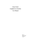
TRAINING MANUAL L Series Graphical User Interface Software Revision: 1.0 Date: August 20, 1997 LSGUI Training Manual 2 1.0 LSGUI Training Manual Table of Contents 1. Introduction.......................................................................................................................................................5 1.1 Program Purpose .........................................................................................................................................5 1.2 Training Manual Purpose ............................................................................................................................5 1.3 Requirements...............................................................................................................................................6 2. LSGUI Installation ............................................................................................................................................9 2.1 Windows 95 Installation procedure...........................................................................................................9 2.2 Windows 3.1 Installation procedure........................................................................................................14 3. LSGUI Main Window.....................................................................................................................................15 3.1 AC Source Information .............................................................................................................................15 3.2 Front Panel Lock .......................................................................................................................................16 3.3 Status Bar ..................................................................................................................................................17 3.4 Command Menu........................................................................................................................................17 3.5 Toolbar......................................................................................................................................................17 3.6 Next...........................................................................................................................................................17 4. Configuration Menu ........................................................................................................................................19 4.1 Model Selection ........................................................................................................................................19 4.2 System Settings .........................................................................................................................................20 4.3 IEEE Interface...........................................................................................................................................20 4.4 User Limits................................................................................................................................................23 5. Source Control Menu ......................................................................................................................................25 5.1 Initialization ..............................................................................................................................................25 5.2 Steady State...............................................................................................................................................26 5.3 Transients ..................................................................................................................................................29 6. Measurement Menu.........................................................................................................................................31 6.1 Standard Measurements ............................................................................................................................31 6.2 Recording measurement data to disk.........................................................................................................33 6.3 Logging Data to a Printer ..........................................................................................................................35 7. Transient Programming...................................................................................................................................37 7.1 Voltage Transients ....................................................................................................................................38 7.2 Frequency Transients ................................................................................................................................41 7.3 Voltage and Frequency Transient..............................................................................................................43 7.4 Saving Transient programs........................................................................................................................44 8. Test Options ....................................................................................................................................................47 9. AC Source Setup Files ....................................................................................................................................49 9.1 Saving front panel setups ..........................................................................................................................49 9.2 Recalling front panel setups ......................................................................................................................50 9.3 Command Line Options ............................................................................................................................50 10. Conclusion ....................................................................................................................................................51 1.0 3 LSGUI Training Manual 4 1.0 LSGUI Training Manual 1. Introduction This training manual was designed to help a new user of California Instruments‘ L Series AC power sources become familiar with the operation of the L Series Graphical User Interface software (LSGUI). This program is included with all programmable versions of this product line. If you are using a manually controlled L Series AC source, this program cannot be used as it requires IEEE-488 bus control. To work through this training manual, it may be useful to have the AC source connected to the PC. This is not required however as the LSGUI will operate in simulation mode in the absence of an IEEE488 connection to an L Series source. 1.1 Program Purpose The LSGUI can be used to control all aspects of the L Series AC power source over the IEEE-488 bus. This allows full PC control without the need to use the front panel of the L Series instrument. All configurations possible in the L Series product line are supported by the same program. The LSGUI is NOT a replacement for a custom Automated Test program that requires the use of multiple IEEE-488 or VXI based instruments. This program only operates the L Series AC source and will ignore all other types of instruments connected to the same bus. It is possible however for other Windows programs to run at the same time as the LSGUI and control other instruments. If your application requires an integrated test program involving multiple instruments from different vendors, we suggest you consider developing your own software. L Series instrument drivers for National Instruments LabView are available free of charge from California Instruments to support this effort. The LSGUI can be used to analyze the bus operation of the -P and -PT programmable controllers using the Abbreviated Plain English (APE) protocol. A command viewer function is available in the LSGUI that allows all bus traffic to and from the L Series AC source to be recorded, printed and or saved to disk. The LSGUI does NOT support the CIIL (ATLAS) protocol which is available as an option on a -P or -PT controller L Series source. The standard APE protocol is the only protocol supported by the LSGUI. If you normally operate the L Series in CIIL mode, you need to switch it to APE by issuing the GAL (Go Alternate Language) command. 1.2 Training Manual Purpose This training manual serves as an introduction to the use of the LSGUI program. It does not replace the LSGUI User Manual that is supplied with the program disk. Not all aspects of the program’s operation are covered in this training manual. You can work through this manual at your own pace by following the steps and examples used to point out the operation of various program aspects. It is important to have the program installed and available while working through this manual. The presence of an L Series AC source is not required however. First time users of the L Series AC source that need to control the AC source from a PC may find it useful to work through this training manual first. If you have not used the LSGUI for a while and need to get back to it for a new project or requirement, you may also benefit from working through this manual as a refresher. 1.0 5 LSGUI Training Manual 1.3 Requirements In order to use the LSGUI program, you will need the following hardware and software items. You will also have to install the LSGUI software and any IEEE-488 interface driver software on your PC. • PC running Windows 3.1, Windows for Workgroups 3.11 or Windows 95. The LSGUI is a 16 bit Windows program and will not operate under Windows NT or any other true 32 bit operating system. The PC you plan to use should have enough CPU processing power and memory (DRAM) to run any of the Windows versions listed above. We recommend at least a 486 class PC with 8 Mbytes of RAM. The LSGUI will run on 386 class PC’s with as little as 4 Mbytes of RAM but performance will be less than satisfactory. • PC Based IEEE-488 Interface Controller. The L Series AC sources support remote control operation using the IEEE-488 General Purpose Instrumentation Bus (GPIB). This means you will need to install a suitable IEEE controller in your PC. Supported IEEE bus controllers include both National Instruments and Hewlett Packard cards. Other vendor IEEE controller cards have not been tested with the LSGUI and may not function. One of the following IEEE controller cards is recommended: National Instruments Hewlett Packard • GPIB-PCII/IIA • HP82335B with SICL drivers • AT-GPIB/TNT • HP82340B with SICL drivers • PCMCIA-GPIB • HP82341C or HP82341D with SICL drivers. Follow the manufacturer’s instruction for card installation. Make sure to install both the hardware (controller card) and any software that is supplied with the card. If you do not, you will only be able to use the LSGUI program in its simulation mode. • LSGUI Program. Make sure you have the latest version of the LSGUI program. If not, some of the features covered in this training manual may not be available to you. You can check your version by selecting the Help About menu which will show you the LSGUI release number. The latest version is available from California Instruments’ website at www.calinst.com. This manual was created using version 1.67. 6 1.0 LSGUI Training Manual • L Series AC Source. L-Series AC power source. Supported models are : 751L Single Phase only 751L 1501L 2000L Single and/or Three Phase 1503L 2750L 4500L 6000L Single and/or Three Phase 9000L 12000L 13500L 18000L Note that the controller must be a -P or -PT type controller (programmable). If you have an -M controller, the LSGUI cannot be used. If you do not have an L Series connected to your PC or you did not install an IEEE-488 bus controller in your PC yet, you can still proceed with this training session as the LSGUI program will operate fully in simulation mode. 1.0 7 LSGUI Training Manual 8 1.0 LSGUI Training Manual 2. LSGUI Installation This section covers installation of the AC source control software under Window 95. If you are using Windows 3.1 or Windows for Workgroups 3.11, the installation procedure is very similar except you use the Program Manager’s File, Run menu to start the SETUP program located on the installation disk. 2.1 Windows 95 Installation procedure To install the AC source control software under Windows 95, proceed as follows: 1. From the Start menu, select Settings. 1. From the Settings options, select Control Panel 2. In the control panel folder, locate the Add/Remove Programs icon 1.0 9 LSGUI Training Manual 10 3. Double click on the Add/Remove Programs icon to launch the Windows 95 Add/Remove Programs property dialog. 4. Click on the Install button located in the top right corner of this dialog box. 5. Insert the first installation disk in drive A and click on the Next button at the bottom of the dialog box. 1.0 LSGUI Training Manual 6. The program will locate the SETUP.EXE program on the first distribution disk and ask for confirmation. 7. Click on Finish to start the installation process. 8. The setup program will now run and display a dialog box that shows the default directory for the AC source control software which is LSGUI on the current drive. At this time you can accept the default directory by clicking on the OK button or enter a different directory. If the directory you enter does not already exist, it will be created. 9. The setup program will now run and display an introduction message explaining the program’s purpose and requirements. If you do not want to install the program, cancel the setup program by clicking on the Cancel button. 1.0 11 LSGUI Training Manual 10. If you do want to install the program, click on Install System. A dialog box will appear next that shows the default directory for the AC Source Control software which is LSGUI on the current drive. At this time you can accept the default directory by clicking on the OK button or enter a different directory. If the directory you enter does not already exist, it will be created. 11. The setup program will create a program group. The default group name used will be LSGUI. You may also elect to store the AC source control program icon in a different group. You may also elect not to add a program icon and group for the AC source control software. In this case, you will have to start the program from the Windows command line or a shortcut for it in the Start menu later. 12. Once you click on OK, the install program will proceed to expand and copy all program and support files to the relevant directories. During this phase, a progress box will be displayed. 12 1.0 LSGUI Training Manual 13. Upon completion of the installation process, a message appears instructing you to register your software with California Instruments. Since products are often shipped to a company address with no reference to the end-user, California Instruments may not have your exact address or email address. By registering both the AC source control software, you will be automatically notified of software upgrades. 14. You can now remove the LSGUI installation disk. 1.0 13 LSGUI Training Manual In Windows 95, the installation program will create a Start menu program group called LSGUI and a program shortcut also called LSGUI. In Windows 3.1, the installation program will create a windows group called LSGUI in the Program manager. We recommend you keep the distribution disks in a safe place in case you ever need to re-install the AC source control software. 2.2 Windows 3.1 Installation procedure The installation under Windows 3.1 or Windows for Workgroups 3.11 is very similar to the one for Windows 95. Instead of using the Control Panel, use the Windows 3.1 File Manager to run the setup program located on the distribution disk. See section 2.1 for further instructions. 14 1.0 LSGUI Training Manual 3. LSGUI Main Window The LSGUI program is started by double clicking on the LSGUI icon under Windows 3.1 or selecting the LSGUI program from the Windows 95 Start Menu, Programs. Each time the program is started, it will try to connect to the L Series AC Source if it was connected at the time the program was closed. If not or if the AC source cannot be found at the same IEEE address, the LSGUI will launch in simulation mode. This chapter will familiarize you with the information displayed on the Main program window. 3.1 AC Source Information The main program window of the LSGUI displays the hardware configuration of the AC source that is connected (or selected in the simulation mode). This information is broken down in three panes which are organized as follows: AC Source: Model Controller IEEE Address Clock/Lock Model number of simulated or connected unit. This is the base model number of the AC source. If you have a unit connected and the model number does not match your unit, you may be in simulation mode. -P or -PT controller. The controller type is obtained by interrogating the AC source configuration. In simulation mode, the LSGUI always uses the PT controller. IEEE address used by the LSGUI to interface to the AC source. This address should match the IEEE address configured on the AC source. Master or Slave mode. Limits: Frequency High Maximum allowed frequency value. For a -P controller, this value will be 2 Khz or 5 Khz. -PT controllers are typically limited to 550 Hz. If an AC source is connected, the actual limits will be queried from the AC source controller and shown here. Frequency Low Minimum allowed frequency value. L Series AC sources support frequencies below this limit at reduced output voltage. The LSGUI will 1.0 15 LSGUI Training Manual automatically trim back the output voltage when the frequency is programmed between 17 Hz and 45 Hz. Voltage Ranges High and Low voltage range limits are shown in this field. The actual ranges of the unit connected may not be 135 V and 270 V. Max. Total Power This field shows the estimated total power output of the AC source. For three phase units or units with the phase mode option, this value is the total apparent power available. Note that this value is based on the product of the voltage range and maximum current limit value reported by the controller. As such, it may not exactly match the power level indicated by the L Series model number. When the LSGUI connects to the AC Source, it tries to determine the model number of the AC source by using this power level value. The L Series does not actually report its model number to the PC so there is no other way to determine the actual model number of the unit connected over the IEEE-488 bus. In simulation mode, this value always shows the nominal rated power level of the unit selected. Options The L Series offers many options, not all of which may be installed on the unit you are using. If you are in simulation mode however, all options are enabled automatically. Output Drop Switch This option is required to perform half cycle drop outs on the L Series AC source. Output Relay Output relays are standard on all L Series. Phase Mode Three phase units can operate in three phase or - if the Mode option is installed, in both single and three phase mode. If this field is Single, it means the AC source only supports single phase mode. Square Wave The square wave option is available in a limited number of configurations. It is not available in simulation mode. Mode Switchable The phase mode allows three phase units to operate in single phase mode as well. MIL-STD-704D This controller firmware based test option allows specific AC tests to be executed automatically. In simulation mode, this option is always available. RTCA/DO-160 This controller firmware based test option allows specific AC tests to be executed automatically. In simulation mode, this option is always available. 3.2 Front Panel Lock The front panel lock check box located in the lower left corner of the Main window is only useful when an AC source is connected to the PC. In this case, this check box allows you to toggle the unit between LOCAL and REMOTE modes. Normally the LSGUI will put the AC source in REMOTE mode, meaning the front panel is locked out. This is the preferred way of operating the unit under PC control as it avoids accidental changes to the setup made from the front panel. The LOCAL mode can be used to release the unit for front panel access. There are situations in which it may be useful to use the front panel. 16 1.0 LSGUI Training Manual 3.3 Status Bar The status bar is always located at the bottom of the Main window, just below the California Instruments logo, and displays important information about the condition of the program and the AC source. It also contains a field that is highlighted in Yellow to indicate the program is connected to an AC source. If you are in simulation mode, this field will be greyed out. Active Interface Connection Simulation Mode NOTE: Make sure you are not in simulation mode when you have a unit connected as the program will appear to be working normally but in reality you are in simulation mode. If you do not have a unit connected, you can only work in simulation mode. 3.4 Command Menu The command menu contains all the menus available for the LSGUI program. From these menu’s, you can access all other screens in the LSGUI. We will cover the individual menus and their purpose in the next chapter. For now, suffice it to say you will be using these menu’s frequently. 3.5 Toolbar A Toolbar is set of iconized short cuts that allow you to access sub menu’s with a single mouse click. The Toolbar can be turned off if needed to free up more screen space. Exercise: 1. Pull down the Options menu and click on the Show Toolbar sub menu. This should turn the toolbar off. 2. Pull down the Options menu and turn the Toolbar back on. As you get more familiar with operating the LSGUI, you may rely on the Toolbar more and more as it gets you to the right screen faster. Each Toolbar button has a yellow tooltip that will popup when you leave the cursor on an icon for more than a second. This tooltip indicates the function of the Toolbar button your mouse is on. 3.6 Next This concludes this brief tour of the Main window. Note that this window mainly provides information on the program and the AC source and does not offer many operational controls other than the Front Panel Lock. In the next chapter we will start exploring some of the available menus. 1.0 17 LSGUI Training Manual 18 1.0 LSGUI Training Manual 4. Configuration Menu The configuration menu provides access to some key screens that allow you to configure the LSGUI to work the way you want. This relates in particular to the IEEE-488 bus settings when you have an AC source connected or the Model number selection screen when you operate in simulation mode. 4.1 Model Selection When the program finds an L Series AC source at the specified IEEE-488 address, it automatically connects to it, retrieves all its configuration data (hardware limits and options) and sets the model number to the correct Model. In this mode of operation, the user cannot change the model number selected since it is fixed by the actual unit connected. In simulation mode however, you are free to select any L Series model you wish to simulate. If you plan to develop transient programs for use on an actual unit however, it is best to select the same model as you ultimately plan to use. Keep in mind however that the unit will have all options available in simulation mode while this may not be the case with your actual unit. Exercise: 1. Pull down the Configuration menu and select the first sub menu called Model... 2. Select the 6000L and make sure the controller selected at the bottom is a -PT type. 3. Click on OK to confirm your selection. If you are in simulation mode, your choice will be accepted. If not, an error message will appear indicating that you are not able to change the model number while connected. 4. Notice that the information on the Main program window has changed to reflect your new selection. Note that in normal operation, there are few instances in which you will have to access this screen as the LSGUI always remembers all settings when the program is closed. The next time you run the LSGUI program, all settings, including the selected model number, are automatically retrieved. 1.0 19 LSGUI Training Manual 4.2 System Settings The system settings sub-menu in the Configuration menu brings up a dialog box that shows all the hardware limits and options for the selected or connected AC source. These settings are determined by the L Series configuration settings and cannot be changed by the user. The same screen also provides access to the Calibration windows. These windows automate output and measurement calibration. If you are authorized to calibrate the L Series, you should know the calibration password. The calibration password needs to be entered in the Calibration Unlock field at the bottom of the dialog box in order to release the Output Cal and Meas Cal buttons on the right hand side. Calibration is outside of the scope of this training manual and is not covered here. Refer to the LSGUI user manual for more information on calibration. Exercise 1. Select the System Settings sub menu from the Configuration menu. 2. Verify that the limits and options match the configuration of your unit if you have a unit connected. 3. If you are in simulation mode, all options will be enabled (except Square Wave and Clock/Lock mode). 4. Close the window to proceed. This screen is normally only provided for information purposes and is not typically needed to run the LSGUI program. 4.3 IEEE Interface The IEEE Interface dialog is an important screen as it allows you to set the interface parameters to the GPIB bus. If these settings are incorrect, you will not be able to successfully use the LSGUI program. The same screen also allows you to toggle the Simulation mode on or off. Finally, the IEEE-488 dialog contains an interactive command line which allows you to send APE commands to the L Series AC sources and read back responses to queries. This command line has a drop down list which contains all available APE commands so you do not have to memorize their syntax. 20 1.0 LSGUI Training Manual Exercise: 1. Pull down the Configuration menu and select the IEEE Interface... sub menu or click on the IEEE connector symbol in the Toolbar. This will bring up the IEEE Address window. 2. Set the IEEE address to 1 or the address that is configured on the L Series unit. The factory default for L Series AC sources is IEEE address 1 but this value can be changed from the front panel of the unit. 3. Select the Card type to match the IEEE controller you are using. If you have an Hewlett Packard type controller card, you must also set the slot number used for this card. The default slot number is 7 but values from 0 to 11 are allowed. 4. If the IEEE address and card type settings are incorrect, you will not be able to communicate with the AC source. 5. If you have an actual unit connected, turn off the Simulation Mode by removing the Check mark. You should now be able to interface to the AC source using the command line. If you do not have an AC Source connected at this time, leave the Simulation Mode enabled and click on OK to close this window. You can proceed to the next paragraph. 6. Use the pull down menu to select a command such as TLK STA (TaLK STAtus). Next click on the Send button to send the command. 1.0 21 LSGUI Training Manual 7. The response to the status query should be displayed in the Response box at the bottom. 8. Use the command line to experiment with other commands. If you enter an unknown command, you will receive an error message. 9. If you have an actual unit connected, click on the OK button. This will cause the LSGUI to connect to the AC source and retrieve all hardware limits and options. The remainder of this training manual will assume you are in simulation mode using a 6000L. You can continue to use the actual source connected through IEEE if you wish. Most exercises will operate largely the same. 22 1.0 LSGUI Training Manual 4.4 User Limits User limits are an important feature of the LSGUI as they allow you to protect your load from accidental over ranging of output parameters such as voltage and frequency. Accidental over ranging is easily done when using slider controls such as the one you will find on the Steady State control panel. (We will cover this panel later). While the AC Source imposes its own hardware limits on voltage and frequency, these limits may exceed what you want to put out. Since these limits are fixed by the hardware, they cannot be changed. The User Limits on the hand are limits you can set as a user. Of course, it is never possible to set a User Limit to a value that exceeds a hardware limit since that would exceed the AC source’s capability. Typically, User Limits are used to set lower limits than what the hardware would normally allow. Good examples of where user limits are valid is for restricting the frequency range between 45 Hz and 66 Hz when working with commercial products or between 395 Hz and 405 Hz when working with avionics products. Exercise: 1. Select the User Limits sub menu from the Configuration menu. (note there is no Toolbar shortcut as user limits are not frequently changed.) This will display the User Limits dialog box. 2. If you do not have access to the Calibration password, you cannot change these user limits. In this case, you will have to skip this exercise. 3. Enter the calibration password and press the Enter key. This will unlock the Frequency and Voltage controls. 4. Change the upper frequency limit to 250 Hz and the lower frequency limit to 50 Hz. 5. Change the High range upper voltage to 240 Volt and the Low range upper voltage to 120 Volt. 1.0 23 LSGUI Training Manual 6. Click on OK to confirm your new User Limit selections. 7. We will study the effects of these new settings in the next chapter. Note: User limits apply to the operation of the Steady State Control panel only. They do not apply when running transient programs. The User Limit values are saved any time the program exits and recalled when the program is started again. Thus, you only need to set these values once. 24 1.0 LSGUI Training Manual 5. Source Control Menu The Source control menu provides access to those functions that are normally controlled from the instrument’s front panel. 5.1 Initialization The L Series initialization system allows you to specify the way the AC source is programmed at power up. Unlike regular test equipment, AC sources typically don’t retain their last setting when a unit is turned off. This is done on purpose to prevent an accidental sudden high voltage output when a unit is turned on. Instead, you can determine how the unit will power up regardless of the setting present when the unit was turned off. However, the initial output voltage can never be set higher than 5.0 Volt rms. The Initialization window located in the Source menu can be used to program the initialization parameters. The following parameters are available: • Initial voltage range • Initial frequency • Initial Voltage (limited from 0.0 to 5.0 Volt) • Initial Current Limit Exercise: 1. Pull down the Source menu and select the Initialization sub menu. This will bring up the Initialization window. 2. This window will display the present power on selections retrieved from the AC source. 3. Change the Voltage range to High and set the frequency to 400 Hz. Note that the frequency is always set to an integer value. (no fractions accepted). Also note that the initial current limit automatically adjusts when you change the voltage range if the previous value exceeds the maximum hardware current limit in the High voltage range. If you change the voltage range back to Low however, the current limit does not adjust as its value is below the hardware limit. 1.0 25 LSGUI Training Manual 4. Notice that you cannot set the voltage higher than 5.0 Volt. 5. Click on OK to close the window. Changes to the initialization settings take effect when you close this window using the OK button. If you click on Cancel instead, all changes you made will be ignored. 6. If you have a unit connected through IEEE-488, you can cycle the power to it off and on and verify that the unit powers up with the new settings. 7. If not, you can open the Initialization window again and verify that your new selections were accepted. The initialization window is not commonly used as it is rarely necessary to change the initialization values of the AC source. 5.2 Steady State The steady state window is the virtual front panel used to control the AC source from the PC. It has controls for all steady state parameters. As we study the steady state panel operation in this chapter, we will turn on the Command Viewer option so you can see the commands being send to the AC source as you operate this window. Note that this window has two modes of operation, Immediate and Update. The default mode is the Immediate mode. In this mode, any change you make to the Steady State window is immediately send to the AC Source. The Update mode on the other hand allows you to make all parameter changes in the Steady State Window first, and then click on the Update button to send all changes to the AC Source at once. The Update mode greatly reduces bus traffic as it only sends the final parameter values you set, not all intermediate values that occur as you slide the controls left and right. You will notice this during this exercise where we will operate in the immediate mode. 26 1.0 LSGUI Training Manual Exercise: 1. Before we go to the Steady State panel, pull down the Options menu and select the Command Viewer. This opens a spy window that will display all bus traffic. If you are in simulation mode, you can still see most bus activity that would normally occur if you had a unit connected. 2. The command viewer can be useful as a learning tool if you want to develop your own test programs. It also allows bus traffic to be saved to disk or copied to another Windows program, which can be useful for troubleshooting communication or programming problems. 3. Pull down the Source menu and select the Steady State sub menu. This brings up the Steady State control window. 4. Use the Frequency slider to change the frequency between its lowest and highest value. Notice that the User Limits you programmed in a prior exercise are in effect and you can’t go above 250 Hz or below 50 Hz. 1.0 27 LSGUI Training Manual 5. Position the cursor in the Frequency text box and enter a value that is outside this range, for example, type in 800 and press the Enter key. Notice that the value send to the AC Source is 250 Hz which is the upper User Limit value. Using this direct data entry method is sometimes faster and more precise than using the slider control. 6. Notice the operation of the slider controls. There are three ways of operating them: 1. By dragging the slider handle. The sweeps the frequency up or down in increments that are a function of the speed at which you drag the slider handle. 2. By clicking on the left or right arrows at each end of the control. This changes the frequency 0.1 Hz at a time. 3. By clicking between the slider handle and the left or right arrows at each end of the control. This changes the frequency by 1 Hz at a time. 7. If you are in simulation mode, you will be able to select the three phase mode. If not, you will only be able to do so if the unit you have connected has the Mode option. If the unit connected is a three phase mode only unit, three phase mode should already be selected and you will not be able to select single phase mode. 8. Set the AC Source to three phase mode (if possible, if not goto step 10). 9. Enable phase B and C by placing a check mark at each phase. This should leave all three phases enabled so any changes you make to voltage or current limit will affect all three phases. 10. Select the High voltage range. Notice the change in current limit. If this value was set to its maximum, it will be reduced by a factor of two. 11. Set the voltage range back to Low range and notice that the current limit value does not change. The LSGUI can only ensure you do not exceed hardware limits of the unit. It does not make a decision on changing user set values other than that. 12. Switch back to High voltage range and set the voltage to 230 Vrms. All phases should now be set to 230 V rms. 13. Set the current limit to maximum. 14. Slide the phase control left and right and notice what happens to Phase A. Since you are not in Slave mode, the phase A phase angle is fixed at 0 degrees. Phase B and C can be changed however. 15. Changing phase angles is not something you often need to do. If you do however, you may not want to turn on B and C controls at the same time. Turn off phase C and set phase B angle to 240 degrees. Now turn of phase B, turn on phase C and set its phase angle to 120 degrees. 16. Finally, close the output relay to apply power to the Unit Under Test. 28 1.0 LSGUI Training Manual 17. The Steady State control panel should now look as shown below. Leave the Steady State control panel open as we may use it later. This window is non-modal and can be left open when returning to the Main window. Note: The Update mode can be used as well but will not show a Command Trace in the Command Viewer while in simulation mode. If you have an AC Source connected however, you are free to use the Update mode instead. 5.3 Transients We will come back to Transients in a subsequent chapter. First we will take a look at some of the measurements that can be made with the L Series controller. 1.0 29 LSGUI Training Manual 30 1.0 LSGUI Training Manual 6. Measurement Menu Measurements can be used to obtain information on load conditions. The LSGUI can obtain all available measurement from the L Series and display them all in a single window. In three phase mode of operation, line to line voltage is calculated from the line to neutral readings supplied by the AC Source controller. These calculations are based on the programmed phase angles between phase A, B and C. 6.1 Standard Measurements Exercise: 1. Pull down the Measurements menu and select the Show... sub menu. This will bring up the Measurement window. 2. If you are in three phase mode, all three phases can be enabled by putting a check mark at each one. Phases are color coded for easier separation. 3. Make sure all parameters are checked. Any unchecked parameter such as Power or Phase will be skipped. 1.0 31 LSGUI Training Manual 4. Click on the Meas. button to start a measurement cycle. Once started, the program cycles through the screen collecting all the selected parameters for the enabled phases. A yellow dot will indicate the presently requested measurement. 5. If you are in simulation mode, the measurement values will be based on the Steady State control panel settings. A random element of fluctuation is added to simulate more realistic measurements. As such, the readings may change slightly between measurement cycles. 6. Select the Cycle mode on the right hand side and start a continuous measurement cycle by clicking on the Meas button again. 7. While the measurement is running, move the mouse to the Steady State control window which should still be open. You can move the window around if needed to make it more visible. You can also re-size and or move the measurement window to make room on the screen. 8. Move the voltage and current limit sliders around and observe the impact this has on the measurements. Your settings and the Measurements should track. 32 1.0 LSGUI Training Manual 6.2 Recording measurement data to disk. Measurements can also be logged to disk for use in other programs. The measurement data files are comma delimited (Comma Separated Value) so they can be imported in a spreadsheet immediately. Before selecting data logging, you should set up the correct file mode and file name. This is done from the Data File Setup window. We will set up a log file and record data for a period of time. Afterwards, we will use a spreadsheet program (if available on your PC) to analyze the data. Exercise: 1. Pull down the Measurement menu and select the Data File... sub menu. This should bring up the Data File Setup window. The measurements can still be running in the background but this will be suspended while the Data File Setup window is open 2. The default file name is ls_data.csv. If you want, you can enter a different file name or use the Browse button to select both a different directory and file name. You can also enter the new file name directly in the file name box. 3. Select the Overwrite mode if it is not already selected. This will cause a new file to be started each time you start a measurement cycle. 4. Select the ASCII string Time Stamp option. This will result in a readable time stamp for each measurement record. The Serial number format is specific to Microsoft Excel. 5. Add a comment in the comment line. This information will be added to the measurement data file and can be a useful reminder of the nature of the UUT from which this data was taken. 6. While in this window, you may also want to turn on the Line to Line voltage option. This will cause the LSGUI to calculate line to line voltage measurements. You Data File Setup window should look like this now: 1.0 33 LSGUI Training Manual 7. Click on OK to confirm your selections and return to the Measurement window. 8. If the measurement window was still open, close it by clicking on the OK button and then open it again from the Measurement menu. This will activate the line to line measurements we have just enabled. The LSGUI only checks this setting when the measurement window is opened. 9. At the bottom of the measurement window is a Log option check box. Turn on data logging by putting a check mark in the log box. The default logging interval is set to 5 seconds which is the minimum time between logging measurement cycles. The maximum time is limited to 3600 seconds or one hour between recordings. 10. Turning the data logging mode on automatically puts the measurement mode to Cycle. Click on Meas. to start the measurement cycle. 11. Use the Steady State control window to vary the voltage and or current limit so all readings will not be the same. Wait about 30 seconds to get at least 5 or 6 records and then click on the Stop button. 12. Toggle to your Windows 95 Explorer or Windows 3.1 File Manager and locate the data file ls_data.csv. If you used a different file, it should be under that name. 13. Open the file using Excel or Notepad if Excel is not available to you. The following table shows a fraction of the data file. #1997-08-21 15:09:52#,"LSGUI training manual exercise" "Date","Time","F","V(A)","I(A)","°(A)","KW(A)","KVA(A)","PF(A)","V(B)","I(B)","°(B)"," 08-21-1997,15:09:53,250.0,223.8,6.2,0.0,1.27,1.39,0.916,236.1,6.6,240.0,1.50,1.57,0.955 08-21-1997,15:09:58,250.0,197.0,6.2,0.0,1.07,1.22,0.883,237.5,6.7,240.0,1.39,1.59,0.875 08-21-1997,15:10:03,250.0,197.5,5.3,0.0,0.95,1.05,0.905,237.2,6.6,240.0,1.44,1.57,0.918 08-21-1997,15:10:08,250.0,260.3,5.3,0.0,1.18,1.38,0.856,237.4,6.7,240.0,1.46,1.59,0.918 14. If you opened the file in Excel, you can use some its graphing capabilities to display one or more parameters as a bar chart or line plot. Close the Excel or Notepad program when you are done with this. 15. Turn off the Data Logging mode by clearing the check mark at the bottom of the Measurement window. 34 1.0 LSGUI Training Manual 6.3 Logging Data to a Printer The measurement data can also be logged to a printer if one is connected to the PC. In this case, the Print check box at the bottom of the Measurement window needs to be checked. If you have a printer connected to your PC and set up under Windows, you can perform the next exercise. If not, just skip this one and go to the next chapter. Exercise: 1. Set a check mark at the Print option at the bottom of the Measurement window. 2. Make sure you are still in Cycle mode. 3. Start a measurement cycle by clicking on the Meas. button. 4. Wait about 30 seconds while moving the voltage and/or current limit sliders in the Steady State control window. 5. Stop the measurement cycle by clicking on the Stop button. The printer should eject the page with the measurement data at this time. If you get no output, use the File, Printer Setup... menu to check for the correct printer selection. 6. Close the Measurement window. Note: Depending on the type of printer you have, lines that exceed more than the page width may be cut off. If this is the case, disable one or more parameters and/or phases so the measurement data fits within the page width. 1.0 35 LSGUI Training Manual 36 1.0 LSGUI Training Manual 7. Transient Programming Transients are a powerful feature of the L Series. To get the most out of the AC Source and LSGUI program, it helps to understand how the L Series implements transient programming. Unlike many SCPI command language based AC sources like California Instruments’ i Series or iL Series, the L Series does not use a sequential list of transient steps. Instead, it has 16 independent transient step registers that can be linked in any sequence if needed. This means each register can stand on its own - it is not linked to any other register - or it can link to any of the other registers, including itself. Thus, register 3 can be used to produce a voltage sweep and then be told to link to itself. The sweep would be repeated indefinitely in this case. For more sophistication, a number of registers can be linked together to form a sequence of events. As long as you don’t run out of registers, you can have multiple event sequences stored in the L Series controller. You can start the one you want by telling the source to start at the register number that is the start of your sequence. The LSGUI creates an easy data entry format for programming the 16 transient registers. Since transient execution is performed by the L Series controller, not the PC, user information needs to be downloaded to the AC source through the IEEE-488 interface before it can be executed. This means that you can edit your data entry grid as often as you want. Until you download the information to the AC source, none of the registers will be affected. You can also leave a register blank by selecting the ‘Empty’ transient type. This will leave the register untouched when you download the information in your data entry grid. The following exercises will make this process more clear. 1.0 37 LSGUI Training Manual 7.1 Voltage Transients Voltage transients only affect the output voltage and can be performed on all three phases at once or any combination of one or more phases. The phase selection box is located in the bottom right corner of the Transient window. Typical voltage transients are drops, steps, surges, sags and sweeps. Each transient step or register has a start and stop value for the voltage and a duration time. If desired, a start phase angle can be specified as well. If no start phase angle is given, the start phase angle will be random. We will set up a few different voltage transients as an exercise: Exercise: 1. Pull down the Source menu and select the Transients... sub menu. 2. Clear the present contents by clicking on the Clear All key located in the bottom right corner of the Window. You will be asked to confirm since this action wipes out the entire grid contents. Click on Yes to acknowledge the fact that you do indeed want to start from an empty grid. Note that the LSGUI always recalls the last Transient setup present when the OK button was clicked. This always allows you to go back to your last transient program, even if you did not save it explicitly. 3. Go to the first row of the grid. It is common practice to start a new program at Register 0 but this is not required. Any register can be the beginning of a transient program. 4. Click on the drop down box and select the ‘V Step’ transient type. 5. Tab over to the right or click on the Goto V field. Notice that only those fields that have to entered are white. All unused field for the V Step function are greyed out. You can enter values in these fields but they will be ignored and any time you move to a new registers, greyed out values will be erased. 6. Enter ‘120.0’ for 120 Vrms. Note that if you are in the Low Voltage range, you should not enter values above the range limit of 135 Vrms. If you do, you will get an error when you try to execute the register contents. The L Series does not automatically switch range to accommodate a higher voltage as this would cause the output to be dropped temporarily. 7. Tab over to the ‘Delay (s)’ field and enter 0.001. This corresponds to 1 millisecond which is the minimum time interval for transient events. Notice we skipped the Phase field as we don’t care about the phase angle of this event. 8. Starting a transient program with a voltage step is good practice as it will ensure you start out at this specific voltage value, regardless of what the steady state value of the source is at the time the register is executed. 9. Tab over to the ‘Link to:’ field and enter number 4. We will use Register 4 as the next event in our transient sequence. 38 1.0 LSGUI Training Manual 10. Move to Register 4 and select ‘V Sweep’ as the transient type. A sweep allows you to go from the Goto V value to the Final V value in a specified period of time. 11. Enter 20.0 V for the Goto V value and 120.0 V for the Final V value. 12. Tab over to the ‘Delay (s)’ field and enter 5.0 for a 5 second sweep. Since we will sweep from 20 Vrms to 120 Vrms in 5.0 seconds, the Voltage slew rate will be (120-20)/5 = 20 V/s. There is no need to know this however as the LSGUI will calculate this value for you and program the register accordingly. 13. Tab over to the ‘Link to:’ field and enter 8. We will use Register 8 as the next event in our transient sequence. 14. Move to Register 8 and select ‘V Srg/Sag’ as the transient type. A Surge/Sag allows you to go to the Goto V value for a specified period of time and then return to the Final V value. 15. Enter 70.0 for the Goto V value and 120.0 for the Final V value. 16. Tab to the ‘Delay (s)’ field and enter 20 ms (0.02). If our frequency is set to 50 Hz, this will cause the output to sag to 70 V for one full period of the AC output and then return back to 120 Vrms. 17. This is the last event in our sequence so we leave the Link field blank. 18. Your Transient window should look like the window shown here at this time. 19. Now that we have programmed our transient program, we need to transfer it to the L Series AC source before we can run it. THIS IS A CRITICAL STEP. If you do not download your transient information to the AC source, clicking on the Start button will not produce the desired result. 1.0 39 LSGUI Training Manual 20. Click on the ‘Dnload Regs’ button to program the L Series AC source controller. If you are in simulation mode, you will see a screen that shows you the command that would have been sent to the AC Source. This can be a useful feature if you plan to develop you own programs for the L Series. Click on Close to go back to the data entry mode. If you have a unit connected, you can run the transient program by selecting Reg 0 in the drop down box at the bottom of the Transient Window and clicking on the Start button. Next we will perform a similar exercise but this time for the frequency. 40 1.0 LSGUI Training Manual 7.2 Frequency Transients Frequency transients only affect the output frequency. As such, they always apply to all three phases. Selecting specific phases only affects the voltage, not the frequency. Frequency transients will always affect all phases present. Exercise: 1. Move to Register 12. We will arbitrarily start at Register 12. 2. Select ‘F Sweep’ as the Transient Type and set the Goto F value to 50.00 Hz and the Final F value to 500.00 Hz. This will cause the frequency to sweep up. 3. Tab to the ‘Delay (s)’ field and set the time to 1.000 seconds. 4. Tab to the ‘Link to:’ field and link to Register 13. 5. Move to Register 13, select ‘F Sweep’ as the Transient Type and set the Goto F value to 500.00 Hz and the Final F value to 50.00 Hz. This will cause the frequency to sweep down. 6. Tab to the ‘Delay (s)’ field and set the time to 1.000 seconds. 7. Tab to the ‘Link to:’ field and link to Register 12. This will cause the transient program to run in an endless 2 second loop sweeping the frequency from 50.0 Hz to 500.0 Hz and back continuously. 18. Your Transient window should look like the window shown here at this time. 19. Now that we have programmed our transient program, we need to transfer it to the L Series AC source before we can run it. THIS IS A CRITICAL STEP. If you do not download your transient information to the AC source, clicking on the Start button will not produce the desired result. 20. Click on the ‘Dnload Regs’ button to program the L Series AC source controller. If you are in simulation mode, you will see a screen that shows you 1.0 41 LSGUI Training Manual the command that would have been send to the AC Source. This can be a useful feature if you plan to develop you own programs for the L Series. Notice the fact that the transient register information from the previous exercise is also sent to the AC Source. Click on Close to go back to the data entry mode If you have a unit connected, you can run the transient program by selecting Reg 12 in the drop down box at the bottom of the Transient Window and clicking on the Start button. You will need to use the Stop button to stop the transient program as it runs in an endless loop. 42 1.0 LSGUI Training Manual 7.3 Voltage and Frequency Transient The Voltage and Frequency Sweep transient is convenient if you want to change both parameters at the same time. You can also use this transient to Step both parameters by using the same values in the Goto and Final Fields. Exercise: 1. Move to Register 2. 2. Select the ‘VF Sweep’ transient type and set the Goto V field to 0.0, the Final V field to 120.0. 3. Set the Goto F field to 50.00 and the Final F field to 500.00. 4. Set the Delay (s) field to 3.000 for a 3 second sweep time. 5. Set the ‘Link to:’ field to 2 to go back to the same register. This will cause this sweep to repeat forever. 18. Your Transient window should look like the window shown here at this time. 19. Now that we have programmed our transient program, we need to transfer it to the L Series AC source before we can run it. THIS IS A CRITICAL STEP. If you do not download your transient information to the AC source, clicking on the Start button will not produce the desired result. 20. Click on the ‘Dnload Regs’ button to program the L Series AC source controller. If you are in simulation mode, you will see a screen that shows you the command that would have been sent to the AC Source. This can be a useful feature if you plan to develop you own programs for the L Series. Notice the fact that the transient register information from the previous exercises is also sent to the AC Source. Click on Close to go back to the data entry mode. If you have a unit connected, you can run the transient program by selecting Reg 2 in the drop down box at the bottom of the Transient Window and clicking on the Start button. You will need to use the Stop button to stop the transient program as it runs in an endless loop. 1.0 43 LSGUI Training Manual 7.4 Saving Transient programs Transients programs can be saved to disk for later recall. This allows you to create a library of commonly used test programs. The transient program information is stored in ASCII text files with a TLS extension. It is recommended that you do not edit these files directly using a text editor but rather use the LSGUI program to edit existing TLS files. You can load any file using the ‘Load List...’ button. The following exercise will show you how to save a transient program, clear the contents of the Transient window and then reload the program we just saved. Exercise: 1. Using the transient program we have created during the previous three exercises, click on the ‘Save List...’ button. 2. This brings up the File Save dialog box shown here. 3. The default directory is the LSGUI program directory. You can change to any directory and/or drive you like. 4. Enter a descriptive file name. Use no more than eight characters as the LSGUI restricts file names to the DOS 8.3 convention. A TLS extension will be added automatically. E.g. use TRAINING 5. Click on OK to save the transient program under this name. 6. Clear the present contents by clicking on the Clear All key located in the bottom right corner of the Window. You will be asked to confirm since this action wipes out the entire grid contents. Click on Yes to acknowledge the fact that you do indeed want to start from an empty grid. 44 1.0 LSGUI Training Manual 7. Now that all your transient information is gone, click on the ‘Load List...’ button and select the TLS file you saved earlier. 8. This restores the transient program you saved earlier. 9. Close the Transient program and return to the Main program Window. In the next chapter we will look at some options that are supported on the L Series for Mil Std 704D and RTCA/DO-160 testing. If you do not have such applications or do not have the options installed in your L Series AC Source, you may skip the next chapter. 1.0 45 LSGUI Training Manual 46 1.0 LSGUI Training Manual 8. Test Options The L Series supports two firmware based options for performing standard AC power related test according to either Mil Standard 704D or RTCA/DO-160. If either option is installed in the L Series, an Applications menu item will appear on the menu bar. If you are in simulation mode, all options are available at all times, including both of these. This chapter will cover RTCA/DO-160 but operation of MIL-STD 704D is nearly identical. Exercise: 1. Pull down the Applications menu and select the RTCA/DO-160 sub menu. If you only have the MIL-STD-704 option, select it instead. 2. These test can be run on an individual phase or on any combination of up to three phases. Many DO-160 tests are run on Avionics systems powered by three phase power. 3. The DO-160 test suite contains three types of tests, Normal, Emergency and Abnormal. We will use one of Normal tests for this exercise. The operation of any of these tests from the LSGUI is basically identical, so if you have seen one, you have seen them all. 4. Select the Voltage Modulation option under Subsections and select a modulation level of 20. This is accomplished using the Combo box behind the Voltage Modulation selection. 1.0 47 LSGUI Training Manual 5. Click on Start to start the test. This test takes 2 minutes. Progress is shown at the bottom of the test window using a progress bar. The Actual command send to the AC source is shown briefly at the bottom of the test window. Afterwards, it switches to show the amount of seconds remaining. 6. You can abort any test prematurely by using the Abort button. The test will be aborted immediately. 7. Close the Test window when you’re done. For detailed information on the nature of each of these sub tests, consult the user manual that was supplied with the AC Source. 48 1.0 LSGUI Training Manual 9. AC Source Setup Files Setup files are used to store AC Source Front panel settings. Only steady state information is contained in these files. All other information is retained in the non-volatile memory of the L Series controller. Setup files always have an STP extension and are saved in an ASCII format. We do not recommend you edit these files however other than through the LSGUI itself. Editing a setup file may corrupt it to the point where it can no longer be recalled. 9.1 Saving front panel setups Setup files are saved through the File menu or from the Toolbar. When you save a setup for the first time, you will always be prompted for a file name. If you saved the setup before or you recalled a setup from disk, the same setup filename will be used for any subsequent save operations unless you use the ‘Save As...’ sub menu option. Exercise: 1. Use the Steady State control window to program the steady state parameters to a specific setting. For example, set the frequency to 100 Hz, voltage to 100 Hz and current limit to 2 Arms. If you are in the Update mode, it is essential to click on the ‘Update Now’ button. If you don’t, the new Steady State values will not take effect and thus, won’t be saved. 2. Close the Steady State control window by clicking on the OK button. 3. Next, pull down the File menu and select the ‘Save’ sub menu. This will bring up the Save As... dialog box since this is the first time since starting the LSGUI that you saved a setup file. As such, you need to supply a file name. 4. Enter a descriptive file of no more than eight characters. The STP file extension will automatically be added. For example, enter TRAINING as the setup file name. 5. Click on OK to confirm your file name assignment. The setup information is now saved to disk. 1.0 49 LSGUI Training Manual 9.2 Recalling front panel setups Next we need to clear the present Steady State settings to make sure the setup file can be used to restore them. This can be done by using the File, New sub menu. 1. Pull down the File menu and select the New sub menu or click on the first icon of the Toolbar (empty sheet icon). 2. Open the Steady State control window to see if the settings have been cleared. The frequency and voltage should be set to their initial values. 3. Close the Steady State control window by clicking on the OK button. 4. Pull down the File menu and select the Open sub menu. This will show you a list of all setup files in the working directory. 5. Select the “training.stp” file and click on OK. This will cause the Steady State settings to be recalled from disk. If you have an AC Source connected through the IEEE-488 bus, it will be programmed with the settings from the setup file. 6. Open the Steady State control window again and confirm that all settings have been restored. 7. Close the Steady State control window when you are done. 9.3 Command Line Options Setup files can be used to program the L Series AC source any time the LSGUI is started by using a command line option. Command line options can be set in the Icon properties under Windows 3.1 or in the Shortcut properties under Windows 95. Setup files have the default file extension .STP and can have a name of up to eight characters. Setup data covers only the Steady State values, the system initialization values, the measurement selections and the data logging selections. System configuration data is not restored from a setup file as it is determined by the actual L-Series unit connected, unless the program is run in simulation mode. In simulation mode, System configuration data is recalled as well. The following is an example of a valid command line setup file entry: C:\LSGUI\LSGUI.EXE C:\TEMP\SETUP.STP The program will load the file called setup.stp located in the temp directory when launched. Note that this may cause the output of the AC source to go to any voltage programmed in the setup file. 50 1.0 LSGUI Training Manual 10. Conclusion This concludes this LSGUI training manual. If you worked your way through all the exercises in this manual, you have seen a good subset of the LSGUI program’s capabilities. If you want to know more, use the LSGUI User Manual that is supplied with the program or refer to the on line help system. All windows have a Help button which gets you directly to the relevant help topic. You can also use the Help menu to see the help table of contents or do a search on a specific topic. If you have any comments about this training manual or the LSGUI, please let us know. We constantly strive to improve our products and meet our customer’s needs. You can email your comments to: Internet Email address [email protected] or fax us at (619) 279-8139 (USA) 1.0 51