1
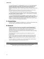
SIERRA VIDEO SVG Multi-Viewer User’s Manual SVG MULTI-VIEWER User’s Manual Sierra Video P.O. Box 2462 Grass Valley, CA 95945 Tel: (530) 478-1000 Fax: (530) 478-1105 Email: [email protected] Version 4.0 Publication Date: October 2013 The information contained in this manual is subject to change by Sierra Video SIERRA VIDEO Regulatory Warnings & Safety Information The information in the following section provides important warnings and safety guidelines for both the operator and service personnel. Specific warnings and cautions may be found throughout this manual. Please read and follow the important safety precautions noting especially those instructions relating to risk of fire, electrical shock and injury to persons. Any instructions in this manual that require opening the equipment cover or enclosure are intended for use by qualified service personnel only. To reduce the risk of electrical shock, do not perform any servicing other than what is contained in the operating instructions unless you are qualified. Warnings Heed all warnings on the unit and in the operating instructions. Disconnect AC power before installing or removing device or servicing unit. Do not use this product in or near water. This product is grounded through the grounding conductor of the power cord. To avoid electrical shock, plug the power cord into a properly wired receptacle before connecting inputs or outputs. Route power cords and other cables so that they are not likely to be damaged, or create a hazard. Dangerous voltages exist at several points in this product. To avoid personal injury, do not touch unsafe connections and components when the power is on. Have qualified personnel perform safety checks after any completed service. To reduce risk of electrical shock, be certain to plug each power supply cord into a separate branch circuit employing a separate service ground. If equipped with redundant power, this unit has two power cords. To reduce the risk of electrical shock, disconnect both power cords before servicing. Operate only with covers and enclosure panels in place – Do Not operate this product when covers or enclosure panels are removed. This is an FCC class A product. In a domestic environment, this product may cause radio interference, in which case the user may be required to take necessary measures. SVG MULTI-VIEWER Cautions Use the proper AC voltage to supply power to the switcher. When installing equipment, do not attach the power cord to building surfaces. Use only the recommended interconnect cables to connect the switcher to other frames. Follow static precautions at all times when handling the equipment. Power this product only as described in the installation section of this manual. Leave the sides of the frame clear for air convection cooling and to allow room for cabling. Slot and openings in the frame are provided for ventilation and should not be blocked. Only an authorized Sierra Video technician should service the switchers. Any user who makes changes or modifications to the unit without the expressed approval of Sierra Video will void the warranty. If installed in a closed or multi-unit rack assembly, the operating ambient temperature of the rack environment may be greater than the room ambient temperature. Therefore, consideration should be given to installing the equipment in an environment compatible with the manufacturer’s maximum rated ambient temperature (TMRA). Installation of the equipment in a rack should be such that the amount of air flow required for safe operation of the equipment is not compromised. Other connections between peripherals of this equipment may be made with low voltage non-shielded computer data cables. Network connections may consist of non-shielded CAT 5 cable. Do not cover chassis ventilation slots or block enclosure openings. FCC Notice This equipment has been tested and found to comply with the limits for a Class A digital device, pursuant to Part 15 of the FCC rules. These limits are designed to provide reasonable protection against harmful interference when the equipment is operated in a commercial environment. This equipment generates, uses, and can radiate radio frequency energy and, if not installed and used in accordance with the instruction manual, may cause harmful interference to radio communications. Operation of this equipment in a residential area is likely to cause harmful interference in which case the user will be required to correct the interference at the expense of the user. The user may find the following publication prepared by the Federal Communications Commission helpful: “How to Identify and Resolve Radio-TV Interference Problems” (Stock number 004-000-00345-4). Available exclusively from the Superintendent of Documents, Government Printing Office, Washington, DC 20402 (telephone 202 512-1800). Warning Changes or modifications not expressly approved by the party responsible for compliance to Part 15 of the FCC Rules could void the user’s authority to operate the equipment. SIERRA VIDEO Power Supply Cords Use only power cord(s) supplied with the unit. If power cord(s) were not supplied with the unit, select as follows: For units installed in the USA and Canada: select a flexible, three-conductor power cord that is UL listed and CSA certified, with individual conductor wire size of #18 AWG, and a maximum length of 4.5 meters. The power cord terminations should be NEMA Type 5-15P (three-prong ground) at one end and IEC appliance inlet coupler at the other end. Any of the following types of power cords are acceptable; SV, SVE, SVO, SVT, SVTO, SVTOO, S, SE, SO, SOO, ST, STO, STOO, SJ, SJE, SJO, SJOO, SJT, SJTOO, SP-3, G, W. For units installed in all other countries; select only a flexible, three-conductor power cord, approved by the cognizant safety organization of your country. The power cord must be Type HAR (Harmonized), with individual conductor wire size of 0.75 mm². The power cord terminations should be a suitably rated earthing-type plug at one end and IEC appliance inlet coupler at the other end. Both of the power cord terminations must carry the certification label (mark) of the cognizant safety organization of your country. A non-shielded power cord may be used to connect AC power to every component and peripheral of the system. Connect an external 16 AWG or larger wire from earth ground to the chassis of the system as designated by the earth ground symbol. North American Power Supply Cords This equipment is supplied with North American power cords with molded grounded plug (NEMA15P) at one end and molded grounding connector (IEC 320-C13) at the other end. Conductors are CEE color coded, light blue(neutral), brown(line), and green/yellow(ground). Operation of the equipment at voltages exceeding 130VAC will require power supply cords that comply with NEMA configurations. International Power Supply Cords If shipped outside North America, this equipment is supplied with molded ground connector (IEC 320-C13) at one end and stripped connectors (50/5mm) at the other end. Connections are CEE color coded, light blue (neutral), brown(line), and green/yellow(ground). Other IEC 320-C13 type power cords can be used if they comply with safety regulations of the country in which they are installed. EMC Regulatory Notices Federal Communications Commission (FCC) Part 15 Information: This device complies with Part 15 of the FCC standard rules. Operation is subject to the following conditions: This device may not cause harmful interference This device must accept any interference received including interference that may cause undesirable operations. Delivery Damage Inspection Carefully inspect the frame and exterior components to be sure that there has been no shipping damage. SIERRA VIDEO Table of Contents Regulatory Warnings & Safety Information FCC Notice Power Supply Cords EMC Regulatory Notices Delivery Damage Inspection 1 2 3 3 3 Overview SVG Multi-Viewer 1 1 Installation Introduction Dimensions Input/ Output Rear Panel Overview RS-232 Connection Timing Connection Single Output System Dual Output System Input Rear Panel SD/HD/3G Input module HDMI Input module CVBS/SDI Input module Output Rear Panel HDMI/VGA Output Card HDMI/HD/SDI Output Card Typical Application 5 5 5 7 7 8 8 9 10 11 11 12 13 14 14 16 17 Configuration Using the Web-Server Basic Physical Configuration Edit Input Source Edit Screens General Configuration System Settings Create a Channel Create a Video Channel Choose an Input Source Video Channel input Source (HD) Make/Delete signal marker Create Clock/ Timer/ Logo Delete an Object Clear All 19 19 20 21 23 24 25 26 27 29 30 31 33 34 34 Screen 1 and Screen 2 35 Quick Tools 36 Alignment Tools 37 Layout Management 38 Download Layout File 39 Upload Layout File 39 HDMI/VGA Output Resolution 39 SDI Output Resolution HDSDI/HDMI Output Card 40 Audio Monitor Output Select 41 Frame Layout 43 Aspect Ratio 43 Input Source 43 Waveform Display 44 UMD and Audio Meters Display 45 Attach to point 45 Position and Size 46 Set Air Timer 46 OSD Elements 47 UMD Settings 47 Dynamic UMD Protocol 50 Tally Settings 51 Via GPI-Static Tally 51 Dynamic Tally Via serial port (RS232) 52 Adjusting the transparency of the Audio and UMD Settings 52 Border Color 53 Extended Settings 54 Serial Port Settings 55 Timing Settings 57 Upload Custom Picture 58 Channel Style 58 Alarms (Detection Settings) 59 User Configuration 63 Network Configuration 64 Upgrade Text file for UMD font 65 Communication Protocols SVG Multi-Viewer Serial Protocol RS-232 Connection Layout Recalls Audio Monitor Selection 67 67 68 68 70 Warranty 73 Contents - 1 SIERRA VIDEO 1 Chapter Overview SVG Multi-Viewer Introduction The SVG uses a 1RU platform with six slots with 3 input card and 2 output card options: Three input module choices: 4xSD input card (auto-sensing CVBS/SDI) 4xHD3G input card (auto-sensing HD/SD SDI up to 1080p) 4xHDMI input card Two output module choices: HDMI+VGA output card: Output resolution of VGA and HDMI signal up to 1920x1200x60p HDMI+HDSDI output card: Output resolution of HDMI signal up to 1920x1080p; (Each output card provides one HDMI input and one RJ45 interface for Ethernet) The SVG is equipped with either a single output card or dual output cards. The single output SVG can hold up to five input cards. So it supports up to 21 (20+1) input signals (the +1 is the HDMI input on the output module). Input sources can be routed (duplicated) to display on any of that specific module's four channels on the single display. The SVG can also be equipped with two output cards, and up to four input cards. So it supports up to 18 (16+2) input signals (the +2 are each HDMI input on the two output modules). Inputs can be assigned to display on any or both outputs. Any channel can be directly and simply moved from one screen to another screen in real-time. Input sources can be routed (duplicated) to display on any of that specific module's four channels on either or both of the SVG's output displays. The SVG is a multi-viewer display system with rich features of high-quality, multi-format inputs, flexible and customizable functions, audio metering, waveform display, real time monitoring and dynamic UMD & Tally from routers with Alarms and audio monitoring. It can be widely used in studio, broadcasting, general control centers, and post-production editing facilities. This makes it ideal for many applications where video/audio monitoring and display are required! 1 SIERRA VIDEO Features 2 Provide high-quality dual outputs with flexible and individual configuration on each output For single output system, it can be 4+1 (using the HDMI input found on the output module) images, 8+1 images, 12+1 images, 16+1 images, or 20+1 images display system For dual outputs system, it can be 4+2 images, 8+2 images, 12+2 images, or 16+2 images display system, and dual outputs share all input sources For dual outputs system, any video channel can be directly and simply moved from one output to another output in real-time. Each input can be displayed in either/both outputs Support the same input signal displaying in different video channels (internal routing) Provide build-in web server to control whole system via RJ45 interface (browser) Audio signals from input sources are selectable to be embedded into HDMI and HDSDI output signal Combine different types of input cards within the same frame (mix/match) Flexible output options: 4:3, 16:9, customized aspect ratio Editable dual program UMD and up to 4 channel audio meters display (Group 1) Provides several kinds of timer: air timer and countdown timers, analog and digital clocks Mark Key signal/signals to find them rapidly in a complicated layout Set the border color of each channel individually or separately or turn borders off Dynamic UMDs &Tally from routers and switchers via RS232 interface (TSL protocol) Support format display of input signal and AFD information display Video/audio auto detection and alarming, such as video loss, video frozen, video black, audio silence, audio overload Two forms of visual alarm: text alarm and icon alarm Supports customized layout to preset various layouts for different application, such as studio, OB van, production room and so on Standard 1RU frame with included dual power supply SVG MULTI-VIEWER SVG Frame Front Panel Frame Back Panel PS1/PS2 Lamps: Indicators with blue lights for dual power supplies operating normally. Reset Button: HDMI/HDSDI Output Module systems only! This feature is not supported on VGAHDMI output module systems. Accessed through the very small hole on the front panel under the PS1/PS2 lamps. This function restores the factory default for the IP address,username and password (192.168.1.76, admin, 000000). Insert a push pin into the small hole, and press the button until there is no picture from HDMI and HD/SD-SDI output (about 5 seconds). Then please restart the device, using the default IP address, username and password. Note The models shown here and in the subsequent sections are fully populated. In some cases, these frames may be configured with more or fewer modules. Consult the rear panel serial number and model number to verify your order and product. The system you receive is customized for the size & type requested at time of purchase from Sierra Video 3 SIERRA VIDEO 2 Chapter Installation Introduction Installation procedures are similar for all frames covered under this manual. Exceptions, if any, have been noted in each of the following paragraphs. Rack Mounting Carefully inspect the frame to ensure that there has been no shipping damage. Make sure all shipping material is removed from the multi-viewer frame. The multi-viewer described in this manual can be rack mounted in a standard 19" (RU) EIA rack assembly and includes rack "ears" at the ends of the front of the frames. It does not require spacing above or below the unit for ventilation. To rack mount any the multi-viewer, simply place the unit's rack ears against the rack rails of the rack, and insert proper rack screws through each of the holes in the rack ears. Always rack mount the multi-viewer prior to plugging the unit into a power receptacle or attaching any cables. CAUTION! The operating temperature range of this product is 0 to 40ºC. Do not exceed the maximum (40ºC) or minimum (0ºC) operating temperature. If installed in a closed or multi-rack assembly, the operating ambient temperature of the rack environment may be greater than the room ambient temperature. Therefore, consideration should be given to installing the equipment in an environment compatible with the manufacturer’s maximum rated ambient temperature. Installation of the equipment in a rack should be such that the amount of air flow to the sides of the multi-viewer required for safe operation is not compromised. Dimensions The SVG multi viewer frame is 1 rack units high, 19” wide, and 20” deep. 5 SIERRA VIDEO Notice In order to avoid network traffic congestion, please do not submit parameters before the last modification is applied. In order to avoid loss of communication between a web browser and the unit caused by continuous operations, please do your second operation after you have gotten the first operation's result. Generally, it will take less than three seconds to get results after you submit a command. The time is related with the monitor type. If the time is too long (over 7 seconds), there may be something abnormal with the hardware’s working status (overheating for example), please wait. Do not plug in HDMI connectors with power on. Without technological guidance from Sierra Video, users are not permitted to remove or insert the modules away from or into the chassis or debug the internal operation. We do not undertake any obligation or responsibility for intentional damage to the SVG. Built-in Web server to control the SVG easily by your computer's browser via Ethernet. Please make sure IP address of SVG is in the same network segment as your computer (first three triplets should be the same, the fourth must be unique). Windows 2003, Windows XP, Windows Vista and Windows 7 are strongly recommended with Internet Explorer web browser. Before powering down the SVG, the user should click the "SAVE" button (on the lower right of the web browser System GUI page) to store all current settings. Otherwise, you may lose some data. The SAVE button stores all current parameters into Flash memory. Users can also upgrade the system under the label “Network.” Before the upgrade, any anti-virus software and firewall have to be closed to make sure that the upgrade data is transmitted to SVG system. Power and network should not be cut off during upgrading. Please set all channels to input inner Test signal without waveform display before an upgrade. This will shorten the time to upgrade the system. If the current output resolution of HDMI signal is not compatible with your monitor, you can change the output resolution on the web browser. 6 SVG MULTI-VIEWER Input/ Output Rear Panel Overview Chassis of SVG series is 1RU frame with six slots. The top row from left to right contains Slot A, Slot C and Slot D. The bottom row from left to right contains Slot S, Slot B, and Slot M. See the picture above. Table-module type allowed inserting into each slot Slot M (Main) S (Slave) A Allowed Module Type Output Card only Input Card/Output Card Input Card only Slot B C D Allowed Module Type Input Card only Input Card only Input Card only Note: For Slot M only allows inserting an output card. For Slot S, when system is single output, it allows inserting an input card; when it is dual outputs, it allows inserting an output card. For example, when one input card is inserted into Slot A, up to four virtual channels can be created from this input card as a channel group named group A. If there is no input card inserted into Slot A, then there is no group A shown on the web browser page. This is the same for Slot B, C and D. Input signals can be only displayed in the virtual channels which are created from the same input card (any input on module A can be displayed on any of the four channels of module A, any input on module B can be displayed on any of the four channels of module B and so on). 7 SIERRA VIDEO RS-232 Connection The RS232 connector is a serial port for multiple functions. Baud rate and parity is configured on the web page. You can achieve multiple functions, such as dynamic UMD and Tally, GPS timing and remote control of layouts, but only one type of control at a time using the serial port. RS232, DB9 definition (For TSL and GPS) Pin # Function 2 Rx 3 Tx 5 GND RS232 to RS232 cable (for Template recall, UMD & Tally and GPS Timing) Pin # PC Pin# SVG 2 3 3 2 5 5 Timing Connection This uses an XLR interface. LTC timing for the SVG is based on EBU/SMPTE time code according to IEC standards. The pin 1 is GND, and pin 2 & 3 receive LTC data. See the picture below. Checking the box “LTC” on the web page enables the LTC timing function, otherwise, timing comes from other selection. See the details about Timing Settings. 8 SVG MULTI-VIEWER Single Output System There is only one output card for SVG single output system. The output card can be HDSDI+HDMI output card, or VGA+HDMI output card. Based on different quantity of input cards, the combination of the SVG configuration is described as following (the +1 refers to the HDMI input on the output module): Qty of Output Cards Qty of Input Cards Combination 1 1 5 pictures (4+1) display system 1 2 9 pictures (8+1) display system 1 3 13 pictures (12+1) display system 1 4 17 pictures (16+1) display system 1 5 21 pictures (20+1) display system 9 SIERRA VIDEO Dual Output System For a dual outputs display system, there are two output cards, which are main output card and slave output card. See the picture above. The main and slave output cards must be the same type (HDMI+HDSDI or HDMI+VGA). Mixing of two different type output cards is not supported. The dual outputs are both configured by the web browser at the same time via the network interface (RJ45) on main output card. The default IP address is 192.168.1.76. And the RJ45 interface on slave output card is invalid with no function (do not connect to this RJ45 interface). Dual outputs system can be configured to be single output system easily via web browser Configuration page (IP: 192.168.1.76/config.html then delete the second channel). Based on different quantity of input cards, the combination of SVG is described as following (the +2 refers to the HDMI inputs on each the two output modules): 10 Qty of Output Cards Qty of Input Cards Combination 2 1 6 pictures (4+2) display system 2 2 10 pictures (8+2) display system 2 3 14 pictures (12+2) display system 2 4 18 pictures (16+2) display system SVG MULTI-VIEWER Input Rear Panel There are three kinds of input modules: SD/HD/3G input module, CVBS/SD-SDI input module, and HDMI input module. SD/HD/3G Input module Supported resolutions: SD: 480i 60, 576i 50 HD: 720p 50Hz/60Hz 1080i 50Hz/59.94Hz/60Hz 1080p 23.976Hz/24Hz/25Hz/29.97Hz/30Hz 3G HD: 1080p 50/59.94/60 The SD/HD/3G input module supports 3G/HD/SD signals with embedded audio and indicates up to 4 audio channels of Group1. The SD/HD/3G input module uses the mini-adapter Tally/Audio interface for Tally signals only. Analog audio signals are not supported with this input module. 11 SIERRA VIDEO HDMI Input module Support resolutions: Video: SD: 480i 59.94, 576i 50 HD: 720p 50Hz/60Hz 1080i 50Hz/60Hz 1080p 24Hz/25Hz/30Hz 1080p 50Hz/60Hz Graphic: 1280x720px50/60Hz 1920x1080px25/30Hz 1920x1080px50/60Hz Supports HDMI signals with embedded audio and indicates up to 4 audio channels of Group1. Supports HDCP protocol. 12 SVG MULTI-VIEWER CVBS/SDI Input module Definition of DB15 interface; Pin # 1 2 3 4 5 Definition Ch1-Aud Ch2-Aud Ch3-Aud Ch4-Aud Ch3-Tally Pin # 6 7 8 9 10 Definition GND Ch1-Tally GND Ch2-Tally GND Pin # 11 12 13 14 15 Definition Support formats: CVBS: NTSC/ PAL SDI: 480i 60/576i 50 Support SDI signal with embedded audio and indicate up to 4 audio channels of Group1. Audio/Tally input module supports one audio channel for each analog composite video signal. 13 SIERRA VIDEO Output Rear Panel There are two types of output modules: HDMI+VGA output module, and HDMI+HDSDI output modules. HDMI/VGA Output Card Each output module provides VGA and HDMI dual output interfaces. Moreover, on the output module, there is a HDMI input and RJ45 interface for Web server. Network RJ45 interface with 10/100/1000M auto-detection. When the system has dual output cards, both output cards are configured by web server with the network interface (RJ45) on the main output card. The default IP address is 192.168.1.76. When facing the rear panel of chassis, if the output card is on the left, it is a slave output card. The RJ45 interface on the slave output is not used and has no function. HDMI OUT HDMI output interface. There is no audio signal embedded into HDMI output signal on the HDMIVGA Output Module, Audio is monitored via the VGA output adapter. The output resolution of the HDMI signal is up to 1920x1200X60p. The output resolutions supported: 1024x768x60p, 1280x720x60p, 1280x768x50p 1280x768x60p, 1280x1024x60p, 1360x768x60p 1366x768x60p, 1400x1050x60p, 1680x1050x60p 1600x1200x60p, 1920x1080x50p, 1920x1080x60p, 1920x1200x60p 14 SVG MULTI-VIEWER HDMI IN HDMI input interface is compatible with both HDMI and DVI signals for input. It supports HDMI signals with embedded audio. There is no display of UMD and audio meters for this HDMI channel on the HDMIVGA Output Module. This module supports the HDCP protocol. The HDMI input channel is always on top of all the channels from input cards. Supported input resolutions of HDMI/DVI signals: Video: SD: 480i 59.94, 576i 50 HD: 720p 50Hz/60Hz 1080i 50Hz/60Hz 1080p 24Hz/25Hz/30Hz 1080p 50Hz/60Hz Graphic: 1280x720px50/60Hz 1920x1080px25/30Hz 1920x1080px50/60Hz VGA Out The VGA output uses a DB15 interface. It provides the VGA output signal and independent analog audio. The display on the VGA output is the same as HDMI output. Supported resolutions of VGA: 1024x768x60p, 1280x720x60p, 1280x768x50p 1280x768x60p, 1280x1024x60p, 1360x768x60p 1366x768x60p, 1400x1050x60p, 1680x1050x60p 1600x1200x60p The VGA/Audio output module can monitor two audio channels from HD/SD/HDMI inputs, and one audio channel of analog composite video inputs, which is provided by the Audio/Tally input module. 15 SIERRA VIDEO HDMI/HD/SDI Output Card Each output module provides HDSDI and HDMI dual outputs. Plus, on each output module, there is an HDMI input and RJ45 interface for Web server connection. Network RJ45 interface with 10/100/1000M auto-detection. When the system has dual output cards, both output cards are configured by the web browser with the network interface (RJ45) on main output card only. The default IP address is 192.168.1.76. When facing the rear panel of chassis, if the output card is on the left, it is a slave output card. The RJ45 interface on the slave output is not used and has no function. HDMI OUT Two HD/SD-SDI audio channels, four HDMI audio channels, or one analog audio signal can be embedded into the HDMI output signal. Users can select audio source via the web browser control to monitor. The output resolution of HDMI signal is up to 1920x1080. The output resolutions are provided as below: 1024x768, 1280x720, 1280x768 1280x1024, 1360x768, 1400x1050 1600x1200, 1680x1050, 1920x1080 HDMI In HDMI input interface. It is compatible of both HDMI and DVI signal to input. And it supports HDMI signal with embedded audio. There is no display of UMD and audio meters for this HDMI channel. Supports HDCP protocol. The HDMI input channel is always on the top of all the channels from input cards. Supported input resolutions of the HDMI/DVI signals: Video: SD: 480i 59.94, 576i 50 HD: 720p 50Hz/60Hz 1080i 50Hz/60Hz 1080p 24Hz/25Hz/30Hz 1080p 50Hz/60Hz Graphic: 1280x720px50/60Hz 1920x1080px25/30Hz 1920x1080px50/60Hz 16 SVG MULTI-VIEWER HDSDI OUT There is an HD/SD-SDI output interface on the output module. HD/SD-SDI interface outputs the same video signal as HDMI interface. So far there is no audio signal embedded into HD/SD-SDI output signal. The output format can be configured via web browser to fixed values as below: 576i 50, 480i 59.94 720p, 1080i, 1080p Typical Application Using the dual outputs system for example below: SVG can be applied in Studio system with two outputs from single device. Input signal sources can be appointed to display on any or both outputs. The SVG can be applied in Production station. Single device can be used in two different rooms for monitoring at same time. Input signal sources can be appointed to display on any or both outputs. 17 SIERRA VIDEO 18 SIERRA VIDEO 3 Chapter Configuration Using the Web-Server The SVG Multi-viewer system has a built-in web server, so users can easily configure it by Internet Explorer (or other browser) when connecting the RJ45 interface of the SVG with an Ethernet cable to a network and the browser computer. First step: Login to 192.168.1.76 to open the general web browser control. There are several tab labels, which are System, Alarm, User, Network, and Help. Default IP address: 192.168.1.76 Default user name: admin Default password: 000000 (six zeroes) Second step: Go to 192.168.1.76/cbvt.html to open the TV Format web browser control. The choices are PAL or NTSC. Select your preferred TV format. After any TV format selection change, a system restart is required. Third step - Configuration: Go to 192.168.1.76/config.html to set the physical configuration of the SVG, such as editing the names of input sources, setting single or dual output screens, and setting the relative positions for the output screens (up/down, down/up, left/right, right/left). Once configured, select Return To System or enter 192.168.1.76 to return to the System (Home) page of the web browser for operation and further configuration of the SVG multi-viewer. Note: Examples in the following sections depict the dual output system. If you have a single output system, configuration screens will only show “first screen.” 19 SIERRA VIDEO Basic Physical Configuration Open web browser and input http:192.168.1.76/config.html to open the physical configuration web page. 20 SVG MULTI-VIEWER Edit Input Source Edit names of each source for each input module's channel on the left column. Note: When the system is a single output system, and there is an input card inserted into slot S, then group S includes channel S1, S2, S3, and S4 (S1 only if there is an output card in slot S). 21 SIERRA VIDEO Description of rear panel. The table of relationship between input source and inserted slots: Slot Module Type Interface on Rear M Output card (Main) HDMI IN (Main) Dual outputs system - Output card HDMI IN S (Slave) (Slave) Single output system - Input card CH1, CH2, CH3, CH4 A Input card inserted into Slot A CH1, CH2, CH3, CH4 B Input card inserted into Slot B CH1, CH2, CH3, CH4 C Input card inserted into Slot C CH1, CH2, CH3, CH4 D Input card inserted into Slot D CH1, CH2, CH3, CH4 Channel Name GUI M1 S1 Group S: S1, S2, S3, S4 Group A: A1, A2, A3, A4 Group B: B1, B2, B3, B4 Group C: C1, C2, C3, C4 Group D: D1, D2, D3, D4 Note: 1. Inputs named CH1~CH4 on the rear panel of input card inserted into Slot A are corresponding to A1~A4 on the browser GUI. The same for Group B, C and D. 2. If there is no input card inserted into a certain slot, like Slot A, the related channel group (channel group A) will not be shown on the web page. 3. The input sources from each input module can only be displayed in its own four channels. For example, input sources from Slot A can only be displayed in one channel or channels from group A. Likewise for group B, C and D. 4. For single output systems, an input card may be mounted in Slot S. For dual outputs, Slot S is occupied by an output card. 22 SVG MULTI-VIEWER Edit Screens 23 SIERRA VIDEO General Configuration There is no need to install any client software, the SVG uses a built-in webserver. Open your favorite web browser and input the IP address (default is 192.168.1.76). Input the user name admin and password 000000.” Click on Login to enter into the operation remote control of the system. Function Overview There are five labels at the top of the web page: System, Alarm, User, Network, and Help. System: To design the output display layout via creating or deleting windows, clock, logo, UMD and other display elements. This is the HOME page within the browser. Alarm: The system supplies detection of audio, mute, frame frozen, black, signal loss, EDH detection. Each alarm threshold can be set to meet your needs. User: The system default user name is admin. The initial password is 000000 which can be changed, and new password will take effect when user logs in the next time. Network: To modify the IP address and upgrade the firmware. The modification will take effect after restart of the machine. Help: To show the versions of each module's firmware. 24 SVG MULTI-VIEWER System Settings You can accomplish the basic configuration and operation in the System Settings, which includes the following functions: to create or delete the channels, to add the clock and logo, to align selected channels via the quick tools, to undo the previous operations, to set parameters, such as output resolutions, aspect ratio, extended configuration, etc. The descriptions are in detail as follows. 25 SIERRA VIDEO Create a Channel The SVG system detects the name of each of the four sources for each input card and makes a list of them according to the settings on the Physical Configuration web browser page (IP: 192.168.1.76/config.html). If there is no input card inserted into a certain slot, such as Slot A, the related channel group, that is channel group A1 through A4, will not be shown on the web page. Each channel group has their own color box. A new channel is added to the output by first clicking on the color box of an input module and then click, drag a box, and un-click (drop) onto either display output. Note: When the system is single output system, and there is an input card inserted into Slot S, then group S includes channel S1, S2, S3 and S4, not just S1 as shown on the dual output module system. 26 SVG MULTI-VIEWER Create a Video Channel 27 SIERRA VIDEO Note: If you skip step 1 (selecting a specific input) and operate step 2 directly, the channels created will increment in the order of number 1 to number 4 as default inputs for each channel of that module. Channel A4 is created as below: For each virtual channel, three details are shown: 1. Channel ID, showing which group it comes from, for example, A4. Each channel has exclusive Channel ID 2. Name of input source displaying in this channel currently, for example, “Router3” 3. Color ID of channel group, distinguishing which group the channel belongs to directly in a complicated layout 28 SVG MULTI-VIEWER Choose an Input Source Note: 1. Input signal sources from each input card can only be displayed on that module's four channels. In other word, input signals and channel group are binding together. 2. When system is single output system, and there is an input card inserted into Slot S, then group S includes channel S1, S2, S3 and S4, not just S1 anymore. 29 SIERRA VIDEO Video Channel input Source (HD) 30 SVG MULTI-VIEWER Make/Delete signal marker Key signals can be marked with red font. Meanwhile, the channel displayed with it will be marked with red border, in order to locate it quickly in a complicated layout, even after a series of position adjustments. Note: You can mark multiple signals at same time. 31 SIERRA VIDEO Note: Multiple signals can be marked at the same time. On the actual output, the channel which uses the signal as the current display source appears in a red border. 32 SVG MULTI-VIEWER Create Clock/ Timer/ Logo The following objects can be created besides video channels. Analog Clock, Digital Timer, Count-down Timer, Air Timer, and Logo. You can create up to two of Analog Clock/ Digital Timer/ Count-down Timer/ Air Timer/ Logo, but on each screen, only one of each object can exist. The size of Logo and Analog Clock cannot be changed. You can change the size of Digital Timer, Count-down Timer, and Air Timer freely. 33 SIERRA VIDEO You can set the time for Air Timer. The Air Timer of each screen can be configured separately. First, click the target screen (each output screen has its own Air Timer), and then press “Set Air Timer” button. There will be a message box popping up (see the picture above). Enter the numbers on three blank areas separately. Then press “OK” button or the Enter key to submit the data. The Countdown timer is the interval time between Air timer and current time. Delete an Object Choose the unnecessary objects (channels/ clock/ Timer/ LOGO), and then click the . The selected one will be deleted immediately. The hot key is button “Delete” on keyboard. Clear All Each screen can be cleared up individually. First, Click anywhere on the needed output screen, and then click the button to clear all the objects on that screen (repeat for second screen if desired). 34 SVG MULTI-VIEWER Screen 1 and Screen 2 Screen 1 is the HDMI or HDSDI output signal of main output card. And Screen 2 is the HDMI or HDSDI output signal of slave output card. The position of two screens is configurable on the Basic Physical Configuration (IP: 192.168.1.76/config.html). Note: If the system is single output system, there is no slave output, that is, there is no virtual “Screen 2” on the web. There are various functions in this area. The main are: 1. Display all the channels, clock, timer and logo 2. Adjust the position of the clock and logo with a mouse in this area 3. Adjust the position and size by dragging the edge of channels with a mouse in this area 4. Adjust the position and size of audio meters and UMD of each channel by dragging the edge of each audio meter or UMD with a mouse in this area 5. Choose one or more objects in this area, before you change its parameters or take further operation 6. Any video channel can be directly and simply moved from one screen to another screen in real-time Each screen can be magnified to full screen to be edited more easily. All the operations in this area display on the monitor or LCD in real time. 35 SIERRA VIDEO Quick Tools There are various quick tools for creating various layouts. Re-Do & Undo = Undo, hotkey is “Ctrl+Z” = Re-Do, hotkey is “Ctrl+Y” 36 SVG MULTI-VIEWER Alignment Tools All operations among these windows are aligned to the last selected one. The buttons below are not only for channels, but also for UMD & Audio Meters as well. The selected audio meter is adjusted according to another one in the same channel. The buttons below can’t be applied for audio meters from different channels. Except for these alignment tools, the SVG software supports hotkeys on the keyboard, such as direction key “↑ ↓ ← →”, in order to move channels in this area. 37 SIERRA VIDEO Full Screen Choose one channel and double click it. The selected channel will output in full screen mode. To return to prior sizing, to quit the full screen mode, use hot key “Ctrl+Z” or click the Undo key . Layout Management The system allows customers to save multiple user-defined layouts. The maximum number of layouts is 20. Layouts can be saved or applied at any time. Save Layout Enter the desired name for the layout in the blank area and click “Save” button. The layout is saved as a thumbnail in the layout management area. The layouts of both screens are saved together at the same time. If the name of the layout already exists, the newly-saved layout will take place of the old one after you confirm to overwrite. Edit Layout Click the thumbnail of the needed layout, and adjust the layout as you needed. After all changes are completed, click the “Save” button. Delete Layout = Delete button Click the delete button on the upper right corner of each layout thumbnail to delete the unnecessary layout. 38 SVG MULTI-VIEWER Download Layout File Click the “Download” button to save all the current layouts (up to 20 maximum layouts) in the form of a BIN file. All the layouts in the layout setting area are saved as one file, so they cannot be downloaded individually. Upload Layout File Click “Browse” button to find and upload the layout file you have downloaded before (default is the Download folder). After successful uploading, the web browser page will automatically refresh and the recalled group of layouts will appear in the layout display area as thumbnails. Apply (recall) a layout by clicking its relevant thumbnail. Note that the latest uploaded layouts will replace the entire original set of layouts. It is suggested to Download current layouts before Uploading a new set as backup/safety precaution. Individual layout recall is not supported. HDMI/VGA Output Resolution Adjust the HDMI or VGA output resolution from main output card and slave output card (they can be set to different resolutions). Color codes indicate EDID information from attached monitor (yellow is supported resolution, green is native/recommended resolution, white (no color code) indicates an unsupported resolution). Choose the needed screen (Screen 1 or Screen 2) first, and choose output resolution in the drop-down list. (Screen 1 is connected with output interface from main output card and Screen 2 is connected with output interface from slave output card.) Note: If the system is single output system, there is no slave output, that is, there is no virtual “Screen 2” on the web. According to different type of output card, menu in the drop-down list is different. 1. For HDMI+HDSDI output card, HDMI output interface provides EDID detection from the monitor. And the resolutions from EDID are highlighted in the dropdown list. See the picture shown above. The output resolution of HDMI signal is up to 1920x1080. 1024x768,1280x720,1280x768 1280x1024,1360x768,1400x1050 1600x1200,1680x1050,1920x1080 39 SIERRA VIDEO 2. For HDMI+VGA output card, VGA and HDMI output resolution are configured at the same time. The output resolution of HDMI signal is up to 1920x1200x60p. 1024x768x60p, 1280x720x60p, 1280x768x50p 1280x768x60p, 1280x1024x60p, 1360x768x60p 1366x768x60p, 1400x1050x60p, 1680x1050x60p 1600x1200x60p, 1920x1080x50p, 1920x1080x60p, 1920x1200x60p HDSDI/HDMI Output Resolution SDI Output For the HDMI+HDSDI output card, the HD/SD-SDI and HDMI interfaces both output the same video signal at the same time. But the SDI output format differs from HDMI output signal, which can be set independently. Embedded audio is the same for both outputs. Choose the needed screen (Screen 1 or Screen 2), and choose output format of the HD/SD-SDI signal in the drop-down list. (Screen 1 is connected with output interface from the main output card and Screen 2 is connected with output interface from the slave output card). Note: If the system is single output system, there is no slave output, that is, there is no virtual “Screen 2” on the web page. Configurable output formats: None, 576i 50/480i 60 (depends if PAL or NTSC), 720p, 1080i, 1080p PAL/NTSC TV format is set on the CBVT.html web browser page: IP: 192.168.1.76/cbvt.html After any TV format selection change, a system restart is required. 40 SVG MULTI-VIEWER Audio Monitor Output Select The processing mode of audio de-embedding is different for the two different types of output cards. 1. For HDMI+VGA output card Audio is monitored via an independent Audio/Tally input module (mini-adapter) attached to the VGA/Audio output module's VGA connector. The system can monitor two audio channels from HD, SDI and HDMI signals, and one audio channel from analog composite input signals. 2. For HDMI+HDSDI output card Audio monitoring for a certain video channel is achieved by monitoring the embedded audio from either the HDMI or HDSDI output signals. A. When the input source is an HD/SD-SDI signal, four channels of HD/SD-SDI audio can be embedded into the HDMI/HDSDI output signal. B. When the input source is an HDMI signal, four channels of HDMI audio signals can be embedded into the HDMI/HDSDI output signal. C. When the input source is CVBS signal, one channel of the analog audio signal can be embedded into the HDMI/HDSDI output signal via the Audio/Tally input module attached to the CVBS input module. Note: If system is single output system, there is no virtual “Screen 2” on the web Choose Screen 1. Available channels in the drop-down list are all located on Screen 1: choose one of them. For the HDMI+HDSDI output cards: the audio signals from input sources, currently displayed in the Audio Output Select menu, are embedded into the HDMI output. For HDMI+VGA output cards, audio is monitored via the audio output interface (mini-adapter) connected to the VGA/Audio output module's VGA connector. 41 SIERRA VIDEO For example, if selecting channel D2, the audio signals on channel D2 are embedded into the HDMI output signal, or monitored via VGA/Audio output module of main output card. Choose Screen 2. And channels in the drop-down list are all located on Screen 2, and then choose one of them. For the HDMI+HDSDI output card, audio signals from input source, currently displayed on the selected channel, are embedded into HDMI output signal of the slave output card. For the HDMI+VGA output card, they are monitored via the audio output interface provided by VGA/Audio output module of the slave output card. For example, if selecting channel B3, audio signals on channel B3 are embedded into the HDMI output signal, or monitored via VGA/Audio output module of the slave output card. Note: Remote serial selection of the input channels to monitor has been added to only the HDHDMI Output Module systems with software release V2.3715S and later. See Section 4 Communication Protocols and the Audio Monitoring Selection pages near the end of this manual. 42 SVG MULTI-VIEWER Frame Layout This function aims to adjust aspect ratio of video image. There are two types of video display: Full channel and Original proportion. Full channel means the video image will cover the entire channel and ignore the aspect ratio of video signal. Original proportion means the video image always keeps the aspect ratio of the original video signal even though the ratio of the channel or the size of UMD and Audio meters are changed. For SD input signals, the aspect ratio of the video image is 4:3 and for HD input signals, it is 16:9. Aspect Ratio This function aims to adjust aspect ratio of virtual channel. Aspect ratio contains 4:3, 16:9, and Free Ratio. 4:3 The size of channels can be changed following the aspect ratio of 4:3 16:9 The size of channels can be changed following the aspect ratio of 16:9 Free Ratio The size of channels can be changed freely (no aspect ratio) Input Source Select the video type between the External Signal (uses the input signals connected to the input modules; CVBS, HDSDI and HDMI) and the test signal generated internally by the system (color bars with moving small white box). 43 SIERRA VIDEO Waveform Display SVG supports the display of real-time waveform. Click the drop-down list, there are three options: None, Waveform one and Waveform two. Waveform one (from top to bottom): Y waveform, PbPr waveform, and Vectorscope Waveform two (from top to bottom): Y waveform, Audio waveforms of G1 CH1, and Audio phase of G1 CH1&CH2. “None” means there is no waveform on the image. "None" needs to be selected to view audio meters (CH 1/2 and CH 3/4). There are no audio meters displayed with waveform one or two. Waveform one: Waveform Two: 44 SVG MULTI-VIEWER UMD and Audio Meters Display Check the box “UMD.” The Under Monitor Display will be shown within the channel. The system supports dual UMD display. Configuration can be set in the “OSD Elements.” Check the box “CH1&2” and audio meters of CH1 and CH2 from the input signal will be displayed within the channel. Check the box “CH3&4” and audio meters of CH3 and CH4 from the input signal will be displayed within the channel. Check the box “Locked.” The audio meters and UMD are locked to the window. Unlocked, both audio meters and UMD can be adjusted in size independently of each other and the window. Locked, they cannot move separately, all move together. Attach to point Check the box and there will be horizontal and vertical lines across both screens. Objects 'snap' to point or align to the lines. You can set the rows and columns to change the amount of lines and density of the cross points, ie., two rows and two columns for 4x4 grid. Un-checking the box removes the guide lines from both screens. Objects are now moved or adjusted freely on either screen. 45 SIERRA VIDEO Position and Size Select an object and the values of that channel’s coordinates, width and height are shown on the right side of the web page. For information only, not adjustable here. Set Air Timer The Air Timer of each display screen can be set separately. First, click the target screen, and then press the “Set Air Timer” button. The Set Air Timer message box pops up (see the picture above). Enter the numbers (hours, minutes, seconds) into the three blank areas separately. Then press “OK” button or the Enter key to submit the data. The countdown timer is the interval time between the Air Timer and the current time. 46 SVG MULTI-VIEWER OSD Elements UMD Settings First, select the needed channel in the drop-down list (the last selected channel is shown by default). The system supports single or dual program UMD displays. Dual UMD is composed of left UMD and right UMD. There is a white line (hyphen) between the left and right UMD text. Single UMD and left / right UMD of Dual UMD can be configured separately. UMD text can be edited via both network (web browser) and Serial port (remote). Via network-Static UMD Choose “Network” in the drop-down list, and click “Settings”. 47 SIERRA VIDEO Upload UMD Text Type the characters in the blank bar, change the color of characters. Click “OK” to submit after all parameters are entered and all characters will be displayed in the UMD. To clear the UMD Enter a “space” and then click “OK.” The characters in UMD area will be cleared. 48 SVG MULTI-VIEWER Via serial port (RS232)-Dynamic UMD Choose “Serial Port” in the drop-down list, and click “Settings” Here are a few steps to achieve dynamic UMD: First, set the baud rate and parity. The baud and parity must be the same as the ones of TSL Tallyman. Please see the detail about configuration of Serial Port in Extended Settings. Second, check the box "TSL” to enable this function. Please see the detail about configuration of Serial Port in Extended Settings. Third, set the target address for selected channel to receive the data from TSL Tallyman. Please make sure there is no duplicate target address for single or dual UMD of the channels, that is, each target address has a unique value, even for right and left UMD of dual UMD display. Note: You can send multiple strings for TSL function at the same time, and the maximum is 10 strings. RS232, DB9 definition (For TSL and GPS) Pin # 2 3 5 Function Rx Tx GND 49 SIERRA VIDEO Dynamic UMD Protocol ---------------------------------------------------------------| HEADER | CONTROL BYTE | DISPLAY DATA | ---------------------------------------------------------------Header = Display address (0-126) + 80 hex (1 byte) (Control byte and display data will be sent) Control (1 byte) bit 0 = tally 1 (1=on, 0=off) bit 1 = tally 2 (1=on, 0=off) bit 2 = tally 3 ( 1=on, 0=off ) bit 3 = tally 4 ( 1=on, 0=off ) bits 4-5 = brightness data bit 4 = 0, bit 5 = 0 (0 brightness) bit 4 = 0, bit 5 = 1 (1/7 brightness) bit 4 = 1, bit 5 = 0 (1/2 brightness) bit 4 = 1, bit 5 = 1 (full brightness) bit 6 = reserved (clear to 0) bit 7 = cleared to 0 Display Data (16 bytes) = 16 displayable ASCII characters in the range 20 hex to 7E hex. All 16 characters must be sent. 50 SVG MULTI-VIEWER Tally Settings Select the needed channel in the drop-down list. Then check the box to enable Tally Display function. The system supports single Tally display. Individual channel Tally can be achieved via both GPI (with the mini-adapter GPI/TALLY interface on CVSD and HD/SD/3G input modules but not the HDMI input module) and Serial port. Via GPI-Static Tally Choose “GPI” in the drop-down list to enable static Tally. Static Tally is applied with the mini-adapter GPI/Tally input module as below. Check the box, when there is a high level trigger, the TALLY area will turn light red; otherwise, dark red. If not check the box, no matter whether there is a high level, the TALLY area will turn gray. High level is the voltage higher than 3.3V and lower than 7V (Caution: higher voltages than 7V will overload the Tally circuit and cause permanent 'high' tally Red lights on all channels of that input module). Users can choose the modified channel from drop-down list. Unchecked box, the Tally area will turn grey. If the box is checked and there is not a high level trigger, the Tally area will turn dark red. If the box is checked and there is a high level trigger, the Tally area will turn light red. 51 SIERRA VIDEO Dynamic Tally Via serial port (RS232) Choose “Serial Port” in the drop-down list to enable Tally. Check the box, the tally is implemented with dynamic UMD of both single UMD and dual UMD. The current color of Tally is changed based on the latest operation of dynamic UMD. Tally 1=Red. Tally 2=Yellow. Adjusting the transparency of the Audio and UMD Settings Choose the target channel (last selected by default) or all channels from the drop -down list. In the area show above, users can modify the transparency of audio meters or UMD of each channel. Choose the channel which needs to be modifed from the drop-down list, put the mouse on the cursor and drag it to the assigned position; or you can fill in a specific parameter ranging from 0 to 255. “0” stands for full transparency and “255” stands for fully opaque. Attach to edge Check “Attach to Edge” when the audio meters and the UMD are located at the bottom and side edges of the image. Attach to Edge places the audio meters and the UMD to the edge leaving that channel's full image be shown. If "Attach to Edge" is not selected, then UMD and audio meters are overlaid (super-imposed) on image based on the transparency set above. Display settings Choose the target channel or all channels from the drop-down list. Check the box “AFD Information” and AFD (Automatic Format Detection) information will be overlaid on the top of the channel, otherwise, not. AFD information is shown in the form of a picture, according to the AFD code embedded in the input signal, else an "X." 52 SVG MULTI-VIEWER Check the box “Input Format” and the input resolution will be overlaid on the top of the channel, otherwise, not. Input resolution is shown as 480i 60/525i 50/720p/1080i/1080p. Check the box "Underscan" to underscan the selected channel. Check the box “Safe Marker.” The pictures of CVBS and SD-SDI signals are marked with 16:9 safe area markers while the pictures of HD-SDI signals are marked with 4:3 safe areas. Check the box “Border.” The selected channel is shown with borders; otherwise, not. The border color of each channel can be configured independently or you can Select All. Border Color Choose the target channel or all channels from the drop -down list, and click “Modify” to show the color palette. Select the desired color and click “OK.” The current border color is changed to the one selected. 53 SIERRA VIDEO Extended Settings Set Color Parameters Brightness: to set the overall brightness and darkness of the full output display picture. The range is from -512 to 511. Saturation: to set the color of the full output display picture. The range is from 0 to 511. Contrast: to adjust the clarity of the full output display picture. The range is from 0 to 511. De-noise: The range of de-noise is from 0 to 63. Default button: to restore to the factory default settings. 54 SVG MULTI-VIEWER Serial Port Settings There are three functions provided by the SVG system via the RS232 interface: RS232 timing (for clocks), TSL UMD & Tally and Template (Layout) Remote Control. Here are a few steps to achieve these functions: First, set the baud rate and parity. The baud and parity must be the same as the ones of the RS232 devices such as TSL Tallyman. Second, check the box "TSL,” “GPS,” or “Template” to enable this function. Only one function can take effect at one time, as they share the same RS232 interface. Third, for TSL UMD & Tally, choose “Serial Port” in the drop-down list under “UMD Settings” of OSD Elements, then set the address for target channel to receive the data from TSL Tallyman. GPS Timing and Layout Remote Control do not use this third step. Note: You can send multiple strings for TSL function (maximum is 10 strings simultaneously). 55 SIERRA VIDEO 56 SVG MULTI-VIEWER Timing Settings There are four kinds of timing mode. They are GPS timing, LTC timing, NTP timing and Local timing (Ethernet connection to web browser computer). Only one timing mode can take effect at a time. See the details of each mode below: GPS timing means that the analog clock and digital timer are controlled by a GPS timer via the RS232 interface. To achieve this function, baud rate and parity should be set. Check the box “GPS,” the GPS timing function is enabled, otherwise, not. LTC timing means timing is based on LTC code via XLR interface. LTC in both SMPTE and EBU code are supported according to IEC standard. Pin 1 is GND, and pin 2 & 3 receive LTC data (see the picture below). Check the box “LTC,” the LTC timing function is enabled, otherwise, not. 57 SIERRA VIDEO NTP timing means the analog clock and digital timer are set by the NTP Server through the RJ45 interface. It supports Network Time Protocol (NTP). The IP address of NTP Server should be configured in the same network segment as SVG, and configure the “NTP Server” under the label of “Network.” Check the box “NTP,” the NTP timing function is enabled, otherwise, not. If you check the box “Local,” the analog clock and digital timer are controlled by the local computer which also accesses the web browser control of the SVG through the RJ45 interface. There are two items required here. First, the local IP address of the web browser computer should be configured in the same network segment as the SVG (first three triplets of the IP address are the same, fourth must be different). Second, refresh the web page after checking the box “Local” in order to submit the current time of the computer to the SVG. The factory default setting of the timing mode is Local. The SVG uses built-in battery-backup for its clock, so that the clock keeps timing when the SVG is powered off. The battery-backed clock stores time for the GPS and LTC time code, but not Local or NTP (assumes those sources always supply the time). Upload Custom Picture The background, logo, and UMD picture of each channel can be changed to a custom one freely through this function. The pictures to upload must be 32bits TGA format with Alpha channel. The size of UMD is 720x60 pixels and the full background size is 960X540 pixels. The amount of data for logo picture must be less than 500KB (also 32bits TGA format with Alpha channel). Channel Style The Channel Style button is not currently supported and has no function. 58 SVG MULTI-VIEWER Alarms (Detection Settings) SVG provides two kinds of warning mode: texts and small icons. And only one mode takes effect at a time. Text is shown at the bottom of each channel. Video warning icon is shown at left edge of each channel, while audio warning is at the right edge. 59 SIERRA VIDEO The video and audio input of each channel can report signal status and validity, with detection of (text and icons): Several channels can be configured at the same time. If the detection parameters of each channel differ from others, the configuration should be completed separately. 60 SVG MULTI-VIEWER Audio Detection The measurement unit of the SVG's digital audio is dBFS(dB Full Scale). 0dBFS is the maximum audio level, corresponding to +24dBu of analog audio. Audio Overload The SVG alarm will prompt a warning picture (text or icon) as soon as the audio level overloads the threshold you have settled. It provides 4 audio channels detection. And there is a box in front of each audio channel. This detection will take effect only if the box is checked. The threshold and duration of detection can be configured for detection of each audio channel. The threshold means a maximum audio level. When the actual volume is above this threshold, the system will prompt with a warning of audio overload. Audio in Silence The SVG will prompt a warning picture (text or icon) as soon as the audio level lowers the threshold you set. It provides up to 4 audio channels of detection with a check box in front of each audio channel. This detection takes effect only if the box is checked. The threshold and duration of detection can be configured for detection of each audio channel. The threshold means the minimum audio level. When the actual volume is below this threshold, the system will prompt warning of audio in silence. 61 SIERRA VIDEO Video Detection Loss of Signal The SVG prompts a warning picture as soon as signal is lost. This detection takes effect only if the box is checked. Video Frozen The SVG will prompt a warning picture as soon as the regular pixels ratio of the image is lower than the threshold you have set. This detection will take effect only if the box is checked. The threshold and duration of detection can be configured. The threshold means the frozen pixel percentage in one frame. Video Black It will prompt a warning picture as soon as video level is lower than the threshold. This detection will take effect only if the box is checked. The duration of detection can be configured. 62 SVG MULTI-VIEWER User Configuration The SVG multi-viewer software provides password-protected functions. The initial (default) user name is admin, and the initial password is 000000 (six zeroes). Users can modify the password with a maximum password length of 12 characters. When you modify the password successfully, the SVG will prompt as "The password is altered successfully. It will take effect when you login next time." 63 SIERRA VIDEO Network Configuration Change IP address User can modify the SVG's IP address. If modified successfully, the system prompts a message box labeled "Network has been configured successfully, please turn off the power and restart the device again.” Restart the device, enter the new IP address into your browser URL and the web software will be opened. Change NTP IP for NTP Timing Configure the “NTP Server” to be the IP address of NTP server for NTP timing. The NTP server and SVG should be in the same network segment. Upgrade firmware of system User can also upgrade the system firmware in this section. Before the upgrade, any antivirus software and firewall have to be closed to make sure that the upgrade data is transmitted to the SVG system without rejection. Windows 2003, Windows XP, Windows Vista and Windows 7 system are strongly recommended to upgrade the system with Internet Explorer, but you can use your preferred browser. Set all channels to input inner test signal without waveform display before initiating the upgrade. This will take less time to upgrade the system than active video inputs. 64 SVG MULTI-VIEWER There are six items for upgrading: Main DSP, Slave DSP 1, Slave DSP 2, Output module, Input module, and Front base file. If there is a new version released, we will supply 1-6 files named according to the items' name. Each item should be upgraded separately one by one - starting with Main DSP. Power and network should not be cut off during upgrading or the upgrade will fail. When the SVG system has upgraded successfully (screen prompt), please turn off the power and restart the SVG again. It takes about 30 minutes to upgrade Slave DSP, about 15 minutes to upgrade the Main DSP and about 5 minutes to upgrade the remaining files. Upgrade Text file for UMD font The” Font” item means you can refresh the font style used for the UMD font from your computer system. The amount of data of the font file must be less than 6MB. Before the upgrade, the anti-virus software and firewall have to be closed to make sure that the upgrade data is transmitted to the SVG system without rejection. 65 SIERRA VIDEO Help Shows the version of current firmware loaded on each module. Main output, Slave output, M1 HDMI input (Slave 0) on the Main output module, S1 HDMI input (Slave 1) on the Slave output module and then each input module (from Slave 2 up to Slave 17 on a fully populated SVG multi-viewer system). 66 SIERRA VIDEO 4 Chapter Communication Protocols Serial Protocol The SVG Multi-Viewer accepts remote serial commands from controllers and serial port communication applications and devices via the RS232 Serial Port. Templates can be recalled serially to make changes to the layout of the output(s). Additionally, since version 2.3715S, the HDHDMI Output Module equipped SVG can support selecting of audio channels to monitor at the display(s) via embedded HDMI or HDSDI output(s). 67 SIERRA VIDEO RS-232 Connection The RS232 connector is a serial port for multiple functions. Baud rate and parity is configured on the web page. You can achieve multiple functions, such as dynamic UMD and Tally, GPS timing and remote control of layouts or audio monitoring, but only one type of control is supported at a time using the serial port. RS232, DB9 definition (for TSL and GPS) Pin # 2 3 5 Function Rx Tx GND RS232 to RS232 cable (for Template recall, Audio monitoring, UMD & Tally and GPS Timing) Pin # PC Pin# SVG 2 3 3 2 5 5 Layout Recalls The serial commands for Layout recalls (templates) must be Hex data strings with the following structure: | header | type | command_1 | parameter_1 |command_2 | parameter| crc32 | Note: The crc32 check is not currently used and can be omitted 0xAA,0x55,0x11,0x20,0x00,0x21,0x01 The Hex data string above is for recall of Layout #1 (farthest to the left in the Layout Management section of the SVG graphical user interface, incrementing by one to the next layout to the right until the far right layout would be #20 on a fully populated layout bar). Byte #: 2 1 1 1 1 1 4 Format:| header | type | command_1 | parameter_1 |command_2 | parameter| crc32 | Up to 20 Layouts can be active on an SVG and each can be remotely recalled by serial commands via the RS232 serial port. The SVG Extended Settings must be set to: Baud Rate: 9600 Parity Check: None Template (Template & Audio Monitoring since V2.3715S) check box must be checked 68 SVG MULTI-VIEWER Serial Commands for Layout recalls (up to 20 can be active on an SVG): Layout # Header Type Cmd 1 Parm 1 Cmd 2 1 0xAA 0x55 0x11 0x20 0x00 0x21 2 0xAA 0x55 0x11 0x20 0x00 0x21 3 0xAA 0x55 0x11 0x20 0x00 0x21 4 0xAA 0x55 0x11 0x20 0x00 0x21 5 0xAA 0x55 0x11 0x20 0x00 0x21 6 0xAA 0x55 0x11 0x20 0x00 0x21 0x21 7 0xAA 0x55 0x11 0x20 0x00 8 0xAA 0x55 0x11 0x20 0x00 0x21 9 0xAA 0x55 0x11 0x20 0x00 0x21 10 0xAA 0x55 0x11 0x20 0x00 0x21 11 0xAA 0x55 0x11 0x20 0x00 0x21 12 0xAA 0x55 0x11 0x20 0x00 0x21 13 0xAA 0x55 0x11 0x20 0x00 0x21 0x20 0x00 0x21 14 0xAA 0x55 0x11 15 0xAA 0x55 0x11 0x20 0x00 0x21 16 0xAA 0x55 0x11 0x20 0x00 0x21 17 0xAA 0x55 0x11 0x20 0x00 0x21 18 0xAA 0x55 0x11 0x20 0x00 0x21 19 0xAA 0x55 0x11 0x20 0x00 0x21 20 0xAA 0x55 0x11 0x20 0x00 0x21 Parm 2 0x01 0x02 0x03 0x04 0x05 0x06 0x07 0x08 0x09 0x0A 0x0B 0x0C 0x0D 0x0E 0x0F 0x10 0x11 0x12 0x13 0x14 69 SIERRA VIDEO Audio Monitor Selection (V2.3715S and later) Any individual audio input can be embedded in the HDMI or HDSDI output from each HDHDMI Output Module connected to each display for monitoring purposes. Serial selection is made by choosing which audio source is embedded for each monitor's speakers. There are forty unique serial commands. Data Structure for Audio Monitoring: header, screen, sound, slot, channel AA 55<Header> 10 <Screen (1/2)> 11 <Sound On/Off> 12 <Slot (M/S/A-D)> 13 <Channel (1-4)> Screen: 1=Main, 2=Second Slot=1, 2, 3, 4, S, M Sound: 0=mute, 1=on Channel: 1, 2, 3, 4 The serial commands for Audio Monitoring selection must be Hex data strings with the following structure: | header | screen | command_1 | parameter_1 |command_2 | parameter| crc32 | Note: The crc32 check is not currently used and can be omitted The Hex data string below is for selection of HDMI and HDSDI embedded Audio Monitoring for Screen #1 (01 main output module), with sound ON (01), using input module in Slot A (41), and listening to input #1 (01). Protocol is Hex data string 0xAA,0x55, 0x10,0x01, 0x11,0x01, 0x12,0x41, 0x13,0x01 The SVG Extended Settings must be set to: Baud Rate: 9600 Parity Check: None Template & Audio monitoring check box must be checked 70 SVG MULTI-VIEWER MAIN DISPLAY AUDIO OUTPUT Audio Monitor A1 0xAA A2 0xAA A3 0xAA A4 0xAA B1 B2 B3 B4 0x55 0x55 0x55 0x55 screen 0x10 0x10 0x10 0x10 0x01 0x01 0x01 0x01 sound 0x11 0x11 0x11 0x11 0x01 0x01 0x01 0x01 slot 0x12 0x12 0x12 0x12 0xAA 0xAA 0xAA 0xAA 0x55 0x55 0x55 0x55 C1 C2 C3 C4 0xAA 0xAA 0xAA 0xAA D1 D2 D3 D4 0x41 0x41 0x41 0x41 channel 0x13 0x13 0x13 0x13 0x01 0x02 0x03 0x04 0x10 0x10 0x10 0x10 0x01 0x01 0x01 0x01 0x11 0x11 0x11 0x11 0x01 0x01 0x01 0x01 0x12 0x12 0x12 0x12 0x42 0x42 0x42 0x42 0x13 0x13 0x13 0x13 0x01 0x02 0x03 0x04 0x55 0x55 0x55 0x55 0x10 0x10 0x10 0x10 0x01 0x01 0x01 0x01 0x11 0x11 0x11 0x11 0x01 0x01 0x01 0x01 0x12 0x12 0x12 0x12 0x43 0x43 0x43 0x43 0x13 0x13 0x13 0x13 0x01 0x02 0x03 0x04 0xAA 0xAA 0xAA 0xAA 0x55 0x55 0x55 0x55 0x10 0x10 0x10 0x10 0x01 0x01 0x01 0x01 0x11 0x11 0x11 0x11 0x01 0x01 0x01 0x01 0x12 0x12 0x12 0x12 0x44 0x44 0x44 0x44 0x13 0x13 0x13 0x13 0x01 0x02 0x03 0x04 S1 S2 S3 S4 0xAA 0xAA 0xAA 0xAA 0x55 0x55 0x55 0x55 0x10 0x10 0x10 0x10 0x01 0x01 0x01 0x01 0x11 0x11 0x11 0x11 0x01 0x01 0x01 0x01 0x12 0x12 0x12 0x12 0x53 0x53 0x53 0x53 0x13 0x13 0x13 0x13 0x01 0x02 0x03 0x04 M1 0xAA 0x55 0x10 0x01 0x11 0x01 0x12 0x4d 0x13 0x01 71 SIERRA VIDEO SECOND DISPLAY AUDIO OUTPUT Audio Monitor A1 0xAA A2 0xAA A3 0xAA A4 0xAA screen sound slot channel 0x55 0x10 0x02 0x11 0x01 0x12 0x41 0x13 0x01 0x55 0x10 0x02 0x11 0x01 0x12 0x41 0x13 0x02 0x55 0x10 0x02 0x11 0x01 0x12 0x41 0x13 0x03 0x55 0x10 0x02 0x11 0x01 0x12 0x41 0x13 0x04 B1 B2 B3 B4 0xAA 0xAA 0xAA 0xAA 0x55 0x55 0x55 0x55 0x10 0x10 0x10 0x10 0x02 0x02 0x02 0x02 0x11 0x11 0x11 0x11 0x01 0x01 0x01 0x01 0x12 0x12 0x12 0x12 0x42 0x42 0x42 0x42 0x13 0x13 0x13 0x13 0x01 0x02 0x03 0x04 C1 C2 C3 C4 0xAA 0xAA 0xAA 0xAA 0x55 0x55 0x55 0x55 0x10 0x10 0x10 0x10 0x02 0x02 0x02 0x02 0x11 0x11 0x11 0x11 0x01 0x01 0x01 0x01 0x12 0x12 0x12 0x12 0x43 0x43 0x43 0x43 0x13 0x13 0x13 0x13 0x01 0x02 0x03 0x04 D1 D2 D3 D4 0xAA 0xAA 0xAA 0xAA 0x55 0x55 0x55 0x55 0x10 0x10 0x10 0x10 0x02 0x02 0x02 0x02 0x11 0x11 0x11 0x11 0x01 0x01 0x01 0x01 0x12 0x12 0x12 0x12 0x44 0x44 0x44 0x44 0x13 0x13 0x13 0x13 0x01 0x02 0x03 0x04 S1 0xAA 0x55 0x10 0x02 0x11 0x01 0x12 0x53 0x13 0x01 MUTE Main 0xAA 0x55 Second 0xAA 0x55 0x10 0x10 0x01 0x02 0x11 0x11 0x00 0x12 0x41 0x00 0x12 0x41 0x13 0x13 01 01 Limitations: Main can only play S1 if from an input module (with S1, S2, S3, S4) Second display cannot play M1 72 SIERRA VIDEO 5 Chapter Warranty A. General Buyer assumes all responsibility for ascertaining the suitability of Sierra Video (hereinafter "SVS") products for Buyer's intended use. No product sold by SVS is designed or manufactured for use in any manner or under any conditions other than those described in SVS's instruction manuals and other printed material for each particular product. If any product is used or applied in a manner or under conditions not specifically authorized by such written materials or if any product is used by unqualified or improperly trained personnel, Buyer agrees that SVS shall have no liability of any kind arising from such use, and Buyer agrees to indemnify and hold SVS harmless from any claims of third parties arising from such use, and Buyer shall provide SVS with counsel of SVS's choice to defend against such claims. B. Limited Warranty 1. This warranty applies only to the original purchaser and is non-transferable. This warranty begins on the date of purchase and will be in effect for five (5) years, 3 years on fans and power supplies, for new equipment or and for three (3) years for "Factory Refurbished" equipment. Buyer must obtain a Return Material Authorization ("RMA") number from SVS prior to returning a product for repair. If, in SVS' sole discretion, the product is found to be defective during the term of this warranty, SVS will at its option: (a) provide free replacement parts, and/or (b) repair the unit at an SVS facility. During the warranty period, SVS will make every reasonable effort to support critical emergencies by supplying no-cost loan equipment while the defective unit is being repaired. SVS will provide replacement parts and/or factory service at no charge. Buyer bears the cost of shipping products returned to SVS under this warranty. SVS will bear the cost of shipping repaired products or replacement parts to the Buyer. This limited warranty shall not apply to any of SVS's goods which have been altered or which shall have been subjected to misuse, mishandling, improper storage or negligence. The aforementioned provisions do not extend the original warranty period of any goods which have been replaced by SVS. This limited warranty shall not apply to any goods not of SVS's manufacture, Buyer to be entitled only to the warranty set forth in the original manufacturer's limited warranty. 73 SIERRA VIDEO THIS LIMITED WARRANTY IS EXPRESSED IN LIEU OF ALL OTHER WARRANTIES, EXPRESS, IMPLIED OR STATUTORY, INCLUDING WITHOUT LIMITATION THE IMPLIED WARRANTIES OF MERCHANTABILITY AND OF FITNESS FOR A PARTICULAR PURPOSE, AND ALL OTHER OBLIGATIONS OR LIABILITIES ON SVS'S PART. SVS neither assumes nor authorizes any other person to assume for SVS any other liabilities in connection with the sale of products of its own manufacture. 2. SVS's liability hereunder on any claim of any kind, except as set forth herein for any loss, injury to person or property or damage, shall in no case exceed the price allocable to the goods which give rise to such claim. 3. In no event shall SVS be liable for any damages or injuries to person or property if any goods do not meet the above limited warranty, including, without limitation, incidental expenses or consequential or special damages, except as set forth in such limited warranty. The foregoing states the exclusive remedy of Buyer and the exclusive liability of SVS for any breach of the foregoing limited warranty. C. Cancellation Except as provided in paragraph B immediately above, all sales are final, and Buyer may cancel this order or return products only upon written consent of SVS. D. General In the event of a breach of any of the terms hereof, the non-breaching party shall be entitled to recover all of its costs, fees, and expenses, including, without limitation, reasonable attorney's fees, from the breach party incurred as a result of such breach, regardless of whether or not a suit is actually filed to enforce the terms hereof. The provision hereof shall be governed by the laws of the State of California (excluding its choice of law provisions). The headings are for convenience only and do not limit or amplify the terms and provisions hereof. In case any one or more of the provisions set forth herein shall be held to be invalid, illegal, or unenforceable in any respect, the validity, legality, and enforceability of the remaining provisions contained herein shall not in any way be affected or impaired thereby. No waiver, alteration, or modification of any of the provisions hereof shall be binding unless in writing and signed by an authorized Officer of SVS. NOTE: All products returned to SVS for service must have prior approval. Return authorization requests may be obtained from your SVS dealer. 74