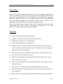
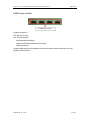
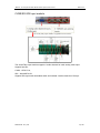
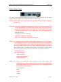
1
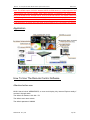
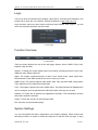
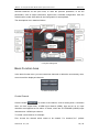
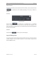
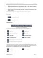
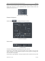
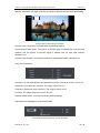
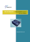
MVS-X 1U compact Multi-viewer system (dual outputs) User manual V1.0 Gefei Tech Co.,Ltd Copyright Copyright © 2009 Beijing Gefei Tech. Co., Ltd all rights reserved. This document may not be copied in whole or in part. Trademarks Gefei-Tech,Magi,MIO,VIO,XIO,MVS,MRS are either registered trademarks or trademarks of Beijing Gefei Tech. Co., Ltd in China and/or other countries. Other trademarks used in this document are either registered trademarks or trademarks of the manufacturers or vendors of the associated products. Disclaimer Product options and specifications subject can be changed without notice. The information in this manual is furnished for informational use only, is subject to change without notice, and should not be construed as a commitment by Beijing Gefei Tech. Co., Ltd .Beijing Gefei Tech. Co., Ltd assumes no responsibility or liability for any errors or inaccuracies that may appear in this publication. Revision Status Rev Date Description May 31, 2009 Initial release of the MVS-X User Manual WEB Software V1.15 Oct 15,2009 release of the MVS-X User Manual WEB Software V2.0 Jan 15,2010 release of the MVS-X (HD/SD) User Manual WEB Software V2.1 April 6, 2010 release of the MVS-X (HD/SD) User Manual WEB Software V2.2 June 6, 2010 release of the MVS-X (HD/SD) User Manual WEB Software V2.5 July 30, 2010 release of the MVS-X User Manual WEB Software V2.5(HD/SD)+ V2.2(CVBS/SD) July 30, 2010 release of the MVS-X User Manual WEB Software V2.7(HD/SD+CVBS/SD+HDMI) Feb 23, 2011 release of the MVS-X User Manual (Dual outputs) WEB Software V1.0 Content Description....................................................................................................................................... 1 Features ........................................................................................................................................... 1 Special Notice ................................................................................................................................. 2 Front Panel ...................................................................................................................................... 3 Input/ Output Rear Panel .............................................................................................................. 3 Input Rear Panel .......................................................................................................................... 4 HD/SD-SDI Input module .............................................................................................. 4 HDMI Input module ........................................................................................................ 5 Output Rear Panel........................................................................................................................ 7 Application ....................................................................................................................................... 8 How To Use The Remote Control Software ............................................................................... 8 Attention before use: ..................................................................................................... 8 Login ............................................................................................................................................ 9 Function Overview ....................................................................................................................... 9 System Settings ............................................................................................................................ 9 Basic Function Area ..................................................................................................... 10 Create Channel ............................................................................................................. 10 Delete Channel ............................................................................................................. 12 Set Time ..................................................................................................................... 12 Clear All .................................................................................................................... 12 Layout Setting Area ...................................................................................................... 12 Operation Area .............................................................................................................. 14 Do & Undo .................................................................................................................... 15 Alignment tools ............................................................................................................ 15 Full Screen .................................................................................................................... 16 Parameters Setting Area ............................................................................................. 17 HDMI Output Resolution .............................................................................................. 17 SDI Output Resolution .................................................................................................. 18 Input Source ................................................................................................................. 18 Video Display................................................................................................................ 18 De-interlacing Filter...................................................................................................... 19 Aspect Ratio ................................................................................................................. 19 Audio Monitor Output Select ....................................................................................... 20 UMD & Audio Meters Display ...................................................................................... 20 Waveform Display ........................................................................................................ 21 Position and Size........................................................................................................... 21 Extended Configuration ................................................................................................ 22 Detection Settings...................................................................................................................... 27 Audio Detection ............................................................................................................ 28 Audio Overload ............................................................................................................ 28 Audio in Silence ............................................................................................................ 29 Video Detection............................................................................................................. 29 Video Overload(Reserved) ...................................................................................... 29 Video Frozen ................................................................................................................ 29 Video Black ................................................................................................................... 30 Loss of Signal................................................................................................................ 30 EDH Detection(Reserved) ..................................................................................... 30 Voice Alarm.................................................................................................................... 30 Detection Parameters Download and Upload .......................................................... 38 UMD & Tally Settings ................................................................................................................. 39 Static UMD .................................................................................................................... 39 Static Tally ..................................................................................................................... 40 Dynamic UMD ............................................................................................................... 41 Dynamic Tally................................................................................................................ 43 User Configuration ..................................................................................................................... 43 Network Configuration .............................................................................................................. 44 Help .......................................................................................................................................... 45 Accessories List .......................................................................................................................... 46 Contact Us .................................................................................................................................. 46 MVS-X:1U compact modular Multi-viewer system User manual Gefei-tech Description MVS-X is a high quality modularized multi-viewer system. According to different needs, users can choose input modules and output modules to form different combination. The max number of input channels is up to 21 displayed in 1U compact frame. It supports 1 HDMI and 1 HD/SD-SDI output. The max output resolution is up to 1920x1200P/60Hz. The most flexible combination and feature-rich platform make it ideal for many applications where video/audio monitoring and display are required! MVS-X also provides various detection of video and audio signal, professional UV meter, programmable UMD, TALLY, digital & analog clock, countdown timer. TSL control protocol V3.1 is also supports in the machine via RS232. Features Multi-format input combination selectable freely CVBS/SDI、HD/SD auto-sensing, analog audio, HDMI input Flexible output resolutions, up to 1920x1200p Provide digital& analog clock, countdown timer Hardware structure, professional DSP accelerated image processing, image after contour correction and anti-flicker processing, color fidelity, no PC operating system, which eliminates the virus infestation Unique AUX window, the background is free to choose, clock replacement is free Any channel can be enlarged to full screen Video/audio auto detection and alarming, video loss, frame frozen, black , audio silence, high rate of accuracy Support various waveforms, such as illumination waveform, PbPr waveform, audio waveform and so on Inner Web Server supports setting configuration parameters by IE browser. Support for large-scale monitoring system showed that the concentration of control and management Preset a variety of commonly used templates for broadcast room, studio, broadcast Gefei Tech. Co., Ltd 1 / 46 MVS-X:1U compact modular Multi-viewer system User manual Gefei-tech vehicles, front-end network Support HDMI (DVI) / HD/SD-SDI dual output Flexible output options: 4:3, 16:9 Provide 4:3 or 16:9 safe maker Support for embedded audio and analog audio, both Chinese and English UMD Support of Tally setting and display Support up to 4CH of group1 PPM meters display The position of UMD and audio meters can be moved freely, and alpha parameters are adjustable Support TSL control protocol V3.1 Redundant power supply chassis, dual fans circulate ventilation structure, operation stable and reliable Special Notice 1 In order to avoid network traffic congestion, please do not submit parameters before the last modification is applied. 2 In order to avoid hardware loose contact caused by continuous operations on the front panel, please do your second operation after you have gotten the first operation result. 3 Generally, it will spend about three seconds to get the results after you submit. The time is related with the monitor type. If the time is too long (over 7seconds), maybe there is something abnormal with the hardware’s working status (overheating for example), please wait patiently. 4 Do not plug the HDMI connector without power-down. 5Without the professional technological guidance from our company, users are not permitted to re-plug the modules away from the chassis or debug the internal operation .We do not undertake any obligation or responsibility of intentional destroy to the machine. 6 Windows 2003, Windows XP, Windows Vista and Windows 7 are strongly recommended with Internet Explorer.exe. 7 User can also upgrade system under the label “Network”. Before the upgrade, the anti-virus software and firewall have to be closed to make sure that the upgrade data is transmitted to MVS-X system without rejection. Power and network cannot be cut off during upgrading. Gefei Tech. Co., Ltd 2 / 46 MVS-X:1U compact modular Multi-viewer system User manual Gefei-tech 8 Please set all channels to input inner test signal without waveform display before upgrade. So it will take less time to upgrade the system. Front Panel Reset Button Reset Button: In the small hole of front panel. The function is to restore the factory value of IP address and user password (192.168.1.76 & 000000). Insert a thin object to the small hole, and press the button until there is no picture from HDMI and HD/SD-SDI output. Then the device is restarting with default IP address and user password. Input/ Output Rear Panel XLR Interface RS232 Serial Port XLR Interface is for LTC timing. RS232 Serial Port is for GPS timing, Dynamic UMD & Tally and Layouts remote. Gefei Tech. Co., Ltd 3 / 46 MVS-X:1U compact modular Multi-viewer system User manual Gefei-tech Input Rear Panel There are three kinds of input module: HD/SD-SDI input module, CVBS/SD-SDI input module, and HDMI input module. HD/SD-SDI Input module The Tally input module is supplied for this interface. Support resolutions: SD: 480i 60, 576i 50 HD: 720p 50Hz/60Hz 1080i 50Hz/59.94Hz/60Hz 1080p 23.976Hz/24Hz/25Hz/29.97Hz/30Hz 1080p 50Hz/60Hz Support HD/SD signal with embedded audio and indicate 4 audio channels of Group1. Gefei Tech. Co., Ltd 4 / 46 MVS-X:1U compact modular Multi-viewer system User manual Gefei-tech HDMI Input module 4 HDMI signal inputs Support resolutions: SD: 480i 60, 576i 50 HD: 720p 50Hz/60Hz 1080i 50Hz/59.94Hz/60Hz 1080p 23.976Hz/24Hz/25Hz/29.97Hz/30Hz 1080p 50Hz/60Hz Support HDMI signal with embedded audio and indicate 4 audio channels of Group1. Support HDCP protocol. Gefei Tech. Co., Ltd 5 / 46 MVS-X:1U compact modular Multi-viewer system User manual Gefei-tech CVBS/SD-SDI Input module The audio/Tally input module is supplied for this interface. The audio/Tally input module supports 1 audio channel for each analog video input. Support formats: CVBS:NTSC/ Pal, SDI:480i 60/576i 50 Support SDI signal with embedded audio and indicate 4 audio channels of Group1. Gefei Tech. Co., Ltd 6 / 46 MVS-X:1U compact modular Multi-viewer system User manual Gefei-tech Output Rear Panel The output module provides HDSDI and HDMI dual outputs. Moreover, on the output module, there is a HDMI input and RJ45 interface for Web server. Network: RJ45 interface with 10/100/1000M auto-detection. And the default IP address is 192.168.1.76. HDMI OUT: Two channel HD/SD-SDI or HDMI audio signals, or one channel analog audio can be embedded into the HDMI output signal. Users can select the video channel where audio signals come from via the web control. The output resolution of HDMI signal is up to 1920x1200. The output resolutions are provided as below: 1024x768, 1280x720, 1280x768 1280x1024, 1360x768, 1400x1050, 1600x1200, 1680x1050, 1920x1080, 1920x1200 HDMI In: The system provides a special channel called “HDMI Input” on the web server for the HDMI input interface. When the HDMI interface input non-3G signal, the channel can display audio meters, UMD, input resolution, safe area and so on. When the HDMI interface input 3G signal (1080p 50/59.94/60), the channel only displays UMD. The HDMI input channel is either above or below all the channels of input modules. The input resolutions are supported as below: SD: 480i 60, 576i 50 HD: 720p 50Hz/60Hz 1080i 50Hz/60Hz 1080p 24Hz/25Hz/30Hz 1080p 50Hz/60Hz HDSDI OUT: There is an HD/SD-SDI output interface on the output module. The embedded audio signals of HD/SD-SDI output signal are the same as the ones of HDMI output signal. The output format can be configured via web server to fixed value as below: 576i 50/480i 60 720p 1080i 1080p Gefei Tech. Co., Ltd 7 / 46 MVS-X:1U compact modular Multi-viewer system User manual Gefei-tech Note: The HDMI output of MVS-X detects HDCP of HDMI device, in order to prevent the video content from copying illegally when video channel is outputted in full screen mode. Only if the HDMI device accepts HDCP, such as LCD and monitor, one certain channel is actually magnified to full screen, otherwise, the channel is on the top of screen and its area is 4/9 of total area. In addition, the HDSDI output is the same as HDMI output, and it is considered as no HDCP when the HDMI output interface isn’t connected to any device. Application How To Use The Remote Control Software Attention before use: MVS-X has a built-in WEBSERVER, so user could deploy it by Internet Explorer easily if connect it through cable. The default IP address: 192.168.1.76. The default user name: admin The default password: 000000 Gefei Tech. Co., Ltd 8 / 46 MVS-X:1U compact modular Multi-viewer system User manual Gefei-tech Login You do not need to install the client software. Open the IE, and input the IP address in the location bar to open the user interface. Default IP address is: http://192.168.1.76. Login interface: input user name: admin and initial code: 000000. Click “login in”, you will enter into the actual operation remote control. 5-1 user login Function Overview 5-2 label option There are many labels at the top of the web page: System, Alarm, UMD & Tally, User, Network, Help and Exit. System: To design the output display layout via creating or deleting windows, clock, logo, UMD and other display elements. Alarm: The system supplies detection of audio, mute, frame frozen, black, signal loss, EDH detection. Each alarm threshold can set to meet your needs. UMD & Tally: The system supports static UMD, static Tally, dynamic UMD, and dynamic Tally. UMD text can be edited and upload here. User:The system supports user name called admin. The initial password is 000000 which can be changed, and new password will take effect when user logs in next time. Network: To modify the IP address and upgrade the firmware. The modification will take effect after restart the machine. Helps: To show the versions of each firmware here. Exit: leave the current operation page. System Settings You can accomplish the basic configuration in the System Settings, which includes the following functions: to create or delete the channels, to add the clock and logo, to align Gefei Tech. Co., Ltd 9 / 46 MVS-X:1U compact modular Multi-viewer system User manual Gefei-tech selected channels via the quick tools, to undo the previous operations, to set the parameters, such as output resolutions, aspect ratio, extended configuration. Click the submit button to take effect after all the configuration is accomplished. The descriptions are in detail as follows. 5-3 System setting area Basic Function Area In the basic function area, you can create new channels or delete the unnecessary ones, even clear all the displayed channels. 5-4 basic functions area Create Channel Click the button “ ” to create a new channel, such as analog clock, countdown timer, air timer, digital timer, a HDMI input channel (HDMI), logo and so on. 21 input channels are supported so far within 1U frame, which are 20 CVBS/SDI (HD/SD) input channels and 1 HDMI input channel. To create a new channel, for example: First, choose the channel which needs to be created. For instance,”ch1” (default Gefei Tech. Co., Ltd 10 / 46 MVS-X:1U compact modular Multi-viewer system User manual Gefei-tech width=200, height=200, horizontal axis=0, vertical axis=0), Then set width=400, height=500, Finally press ok button to finish the creation. The size of analog clock and logo is not adjustable. The analog clock and digital timer are controlled by computer though RJ45 interface as default settings. At extended configuration, they can be set to be controlled by GPS timer, LTC time code, or NTP server. 5-5 create a channel It’s allowed to adjust the parameters of the selected channel after it has been created. Click “Save” button after each operation. Please refer to the details on operation area. The information of the selected channel is indicated here, where you can also set the parameters. 5-6 indicate information of the new channel Gefei Tech. Co., Ltd 11 / 46 MVS-X:1U compact modular Multi-viewer system User manual Gefei-tech Delete Channel Choose the unnecessary objects (window/clock/Timer/LOGO), and then press the button “ ”. The selected one will be deleted immediately. The hot key is “Delete” on keyboard. Set Time 5-7 set the air timer Press the button “ ” to set target time. “h” represents hour,. “m” represents minute. “s” represents second. Enter the numbers on three blank areas separately. Then press submit button to submit the data. The countdown timer is the interval time between air timer and current timer. Clear All Press the button“ ”, and then clear up all the objects. Layout Setting Area The system provides various default layouts and allows to save the new layouts that the customer designed. The max number of layouts is 5 for the customer. Layouts can be saved or applied any time. Gefei Tech. Co., Ltd 12 / 46 MVS-X:1U compact modular Multi-viewer system User manual Gefei-tech Name the layout you designed and click the submit button. Default layouts provided by system 5-8 name and save layouts you designed The default layouts can be edited and saved as a new layout, but cannot be deleted. The layout is saved successfully. You can edit or delete it. 5-9 the layout is saved successfully Each layout is saved as a thumbnail. Click this thumbnail apply the relevant layout. There are two buttons under this thumbnail: Edit and Delete. Layouts can be edited and deleted through these buttons. Gefei Tech. Co., Ltd 13 / 46 MVS-X:1U compact modular Multi-viewer system User manual Gefei-tech The layout management : Layouts export and import. 5-10 the Layout management Click Management button, pop out a dialogue box called Layout Management. Download and upload the layouts by clicking the relevant button. 5-11 layout management Export layouts: Click Download button and save the layouts you just designed in form of a BIN file. All the layouts in layout setting area are saved as one file, so they can’t be downloaded individually. Import layouts: Click Browse button and upload the layout file you just downloaded. The layouts will appear in layout setting area as thumbnails. And apply a layout by clicking its relevant thumbnail. Note that the latest uploaded layouts will replace the original one. Operation Area There are various functions in this area. The main are following: 1. Display all the channels ,clock, and logo; 2. Adjust the position of the clock and logo with a mouse in this area; 3. Adjust the position and size by dragging the edge of channels with a mouse in this Gefei Tech. Co., Ltd 14 / 46 MVS-X:1U compact modular Multi-viewer system User manual Gefei-tech area; 4. Adjust the position and size of audio meters and UMD of each channel by dragging the edge of each audio meter or UMD with a mouse in this area; 5. Choose one or more objects in this area, before you change its parameters or take further operation. All the operations in this area display on the monitor or LCD in real time. Do & Undo : undo, hotkey is “Ctrl+Z”; :do, hotkey is “Ctrl+Y”。 Alignment tools 5-12 quick tools for channels alignment All operations among these windows are aligned to the last selected one. :Align Top :Align Bottom :Align Horizontal Center :Align Left :Align Right Align Vertical Center :Horizontal Average :Vertical Average : Overspread with horizontal equal width : Overspread with vertical equal height The buttons below are not only for channels, but also for UMD & Audio Meters as well. The selected audio meter is adjusted according to another one in the same channel. The buttons below can’t be applied for audio meters from different channels. :Equal Width :Equal Height :Equal Width & Height. Gefei Tech. Co., Ltd 15 / 46 MVS-X:1U compact modular Multi-viewer system User manual Gefei-tech Except these alignment tools, the software supports hotkey on the keyboard, such as , in order to move channels in this area. Full Screen : Full Screen. Choose one channel and click this button. The selected channel will output in full screen. Full screen function also can be accomplished by double clicking the channel. When you want to quit the full screen mode, please use hot key “Ctrl+Z” or click . Note: The HDMI output of MVS-X detects HDCP of HDMI device, in order to prevent the video content from copying illegally when video channel is outputted in full screen mode. Only if the HDMI device accepts HDCP, such as LCD and monitor, one certain channel is actually magnified to full screen, otherwise, the channel is on the top of screen and its area is 4/9 of total area. In addition, the HDSDI output is the same as HDMI output, and it is considered as no HDCP when the HDMI output interface isn’t connected to any device. Gefei Tech. Co., Ltd 16 / 46 MVS-X:1U compact modular Multi-viewer system User manual Gefei-tech Parameters Setting Area 5-13 parameters settings area HDMI Output Resolution 5-14 HDMI output resolution HDMI output interface provides EDID detection from the monitor. And the resolutions from EDID are highlighted in the dropdown list. See the picture shown above. The output Gefei Tech. Co., Ltd 17 / 46 MVS-X:1U compact modular Multi-viewer system User manual Gefei-tech resolution of HDMI signal is up to 1920x1200. 1024x768,1280x720,1280x768 1280x1024,1360x768,1400x1050 1600x1200,1680x1050,1920x1080,1920x1200 SDI Output Resolution 5-15 SDI output format HD/SD-SDI and HDMI interface produce output signal at the same time with the same video content and embedded audio. But the SDI output format is different from HDMI output signal, which can be set independently. None 576i 50/480i 60 720p 1080i 1080p Input Source 5-16 input source Select the video type between the External Signal (HD/SD-SDI) and the test signal generated by the system. Video Display 5-17 video display There are two types of video display: Full channel and Original ratio. Gefei Tech. Co., Ltd 18 / 46 MVS-X:1U compact modular Multi-viewer system User manual Gefei-tech Full channel means the video image will cover the entire channel and ignore the aspect ratio of video signal. Original ratio means the video image always keeps the aspect ratio of video signal even though the ratio of the channel or the size of UMD and Audio meters are changed. So for SD input signal, the aspect ratio of video image is 4:3;And for HD input signal, it is 16:9. De-interlacing Filter 5-18 De-interlacing Filter This function is suitable for high-end customs to make motion video played smoothly without tailing and saw tooth. The function includes Interlaced Output, two fields filtered Output, three fields filtered Output, three fields filtered and Enhanced Output, three fields filtered and dynamic Enhanced Output. Click the Save button to take effect. Aspect Ratio 5-19 aspect ratio Aspect ratio contains 4:3, 16:9, and full screen to change the ratio of channels. Gefei Tech. Co., Ltd 19 / 46 MVS-X:1U compact modular Multi-viewer system User manual Gefei-tech Audio Monitor Output Select 5-20 audio output select The audio monitor for one certain channel is achieved by monitoring the embedded audio of HDMI or HD/SD-SDI output signal. A,When the input source is HD/SD-SDI signal, two channel HD/SD-SDI audio signals can be embedded into the HDMI and HD/SD-SDI output signal. B,When the input source is HDMI signal, two channel HDMI audio signals can be embedded into the HDMI and HD/SD-SDI output signal. C, When the input source is CVBS signal, one channel analog audio signals can be embedded into the HDMI and HD/SD-SDI output signal via the audio/Tally input module. UMD & Audio Meters Display 5-21 UMD, audio meters, and locked status Check the box “UMD”. It will be shown within the channel, otherwise, not. The details can be completed in label “UMD & Tally”. Check the box “Audio”, and the 4 CH VU meters will be shown within the channel, otherwise, not. Check the box “Locked”. The audio meters and UMD are locked with widow. So the audio meters or UMD can’t be operated separately. Otherwise, can. Gefei Tech. Co., Ltd 20 / 46 MVS-X:1U compact modular Multi-viewer system User manual Gefei-tech Waveform Display 5-22 Waveform display Multi-viewer V2.7 supports the display of real-time waveform image overlay. Click the drop-down list, there are three options: None, Waveform one and Waveform two. Waveform one (from top to bottom): Luminance waveform, PbPr waveform, chrominance vector diagram; waveform two (from top to bottom): Illumination waveform, audio waveforms of G1 CH1, and audio phase diagram of G1 CH1&CH2. Choose “None” means there is no waveform on the image. Each time after the selection, click save button to make application effect. There will not be audio meters with waveform display. 5-23 Waveform one of HD/SD-SDI input module 5-24 Waveform two of HD/SD-SDI input module Position and Size There are three ways to adjust a channel’s the coordinates, width and height. The first is to drag the edge of the selected channel directly with the mouse in the operation area; the Gefei Tech. Co., Ltd 21 / 46 MVS-X:1U compact modular Multi-viewer system User manual Gefei-tech second is to enter the exact number of the coordinates, width and height in the parameter setting area; the last is to set the parameters when create the channel, which was described in the title of 5.2.2.1. 5-25 set coordinates, width & height Extended Configuration Click the button ,prompting the dialog box as follow: 5-26 extended configuration Display settings 5-27 display settings Choose the target channel or all channels from the drop -down list. Check the box “AFD Pictures” and AFD information will be overlaid on the top of the channel, otherwise, not. AFD information is shown in the form of picture, according to the AFD code inside of input signal. Check the box “Input Resolution”, and input resolution will be overlaid on the top of the Gefei Tech. Co., Ltd 22 / 46 MVS-X:1U compact modular Multi-viewer system User manual Gefei-tech channel, otherwise, not. Input resolution is shown as 480i 60/525i 50/720p/1080i/1080p. 1080i 5-28 the effect of AFD and input resolution Check the box "Underscan" to make effect for selected channel. Check the box “Safe areas”. The picture of SD-SDI signal is marked with 16:9 safe area markers, and the picture of HD-SDI signal is marked with 4:3 safe area markers, otherwise, not. Check the box “Border”, the selected channel is showed with border; otherwise, not. Set Color Parameters 5-29 color Parameters Luminance: to set the brightness and darkness of picture. The range is from -512 to 511. Saturation: to set the color of picture. The range is from 0 to 511. Contrast: to adjust the clarity of picture. The range is from 0 to 511. De-noise: The range of de-noise is from 0 to 63. Restore default button: to restore the factory default settings. Adjustment the transparency of Audio and UMD 5-30 adjustment the transparency of Audio and UMD Gefei Tech. Co., Ltd 23 / 46 MVS-X:1U compact modular Multi-viewer system User manual Gefei-tech In this area, users can modify the transparency of audio meters or UMD of each channel. Choose the channel which needs to modify from the drop-down list, put the mouse on the cursor and drag it to the assigned position; or you can fill in the certain parameter ranging from 0 to 255. “0” stands for full transparency and “255” stands for opacity Attach to edge Check “Attach to Edge”, when the audio meters and the UMD are located at the bottom edge of the image, let the audio meters and the UMD cling to the edge which make the image be shown completely. Users can choose the modified channel from drop-down list. Upload Custom Picture and Set black background 5-31 upload custom picture The background, logo, and UMD picture of each channel can be changed to custom one freely through this function. The picture you need to upload must be 32bits TGA format with Alpha channel. The size of picture is 720x60 pixels for UMD and 864X486 pixels for background. The amount of data of logo picture must be less than 128K, and also should be 32bits TGA format with Alpha channel. Check the box “Black BK” and the background will be set to black immediately. Uncheck the box to cancel black background. The default background is black. Series Ports Settings 5-32 Series Ports Settings There are two functions provided by MVS-X system via a RS232 interface, which are RS232 timing and TSL UMD & Tally. Here are a few steps to achieve these functions: First, set the baud rate and parity. The baud and parity must be the same as the ones of RS232 devices such as TSL TallyMan. Second, check the box "TSL” or “GPS” to enable this function. Only one function can take effect at one time, because they share the same RS232 interface. Third, for TSL UMD & Tally, check the box “Dynamic UMD” under the label of “UMD & Tally”, then set the address for target channel to receive the data from TSL TallyMan. Gefei Tech. Co., Ltd 24 / 46 MVS-X:1U compact modular Multi-viewer system User manual Gefei-tech GPS Timing doesn’t need the third step. NOTE: you can send multiple strings for TSL function at the same time, and the maximum is 10 strings. RS232, DB9 definition (For TSL and GPS) Pin Function 2 Rx 3 Tx 5 GND RS232 cable connection 2-----------------------3 3------------------------2 5------------------------5 “Touch screen” is reserved. Time Sync Settings 5-33 Timing Settings Under the new version (V2.7) of MVS-X, there are four kinds of timing mode. They are GPS timing, LTC timing, NTP timing and Local timing. Only one timing mode can take effect at a time. See the details of each mode below: GPS timing means that the analog clock and digital timer are controlled by GPS timer via RS232 interface. To achieve this function, baud rate and parity should be configured. Please refer to the description about “Series Ports Settings” of “Extended configuration”. Check the box “GPS”, the GPS timing function is enabled, otherwise, not. Gefei Tech. Co., Ltd 25 / 46 MVS-X:1U compact modular Multi-viewer system User manual Gefei-tech Two “GPS” options are bound together. Check one of them, and another one is also checked. 5-34 GPS timing LTC timing means timing is based on LTC code via XLR interface. So far the LTC of MVS-X is EBU code according to IEC standard. The pin 1 is GND, and pin 2 & 3 receive LTC data. See the picture below. Check the box “LTC”, the LTC timing function is enabled, otherwise, not. Pin 1—GND Pin 2—LTC+ Pin 3—LTC- 1 3 2 5-35 LTC timing NTP timing means the analog clock and digital timer are set by NTP Server through RJ45 interface. It supports Network Time Protocol (NTP). The IP address of NTP Server should be configured in the same network segment as MVS-X, and configure the “NTP Server” under the label of “Network”. Check the box “NTP”, the NTP timing function is enabled, otherwise, not. If check the box “Local”, the analog clock and digital timer are controlled by computer which also accesses to the web control of MVS-X through RJ45 interface. There are two items that required notice. First, the local IP address of computer should be configured in the same network segment as MVS-X. Second, refresh the web page after checking the box “Local”, in order to submit the current time of computer to MVS-X. The factory setting of timing mode is Local timing. Check the box “Local”, the local timing function is enabled, otherwise, not. MVS-X adopts built-in battery-backed clock, so that the clock keeps timing when MVS-X is cut power off. The battery-backed clock stores time corrected by GPS or LTC time code, not Local or NTP. Gefei Tech. Co., Ltd 26 / 46 MVS-X:1U compact modular Multi-viewer system User manual Gefei-tech Detection Settings 5-36 detection settings :Check all the boxes for channels :Selected will be clear, the others will be selected. :Cancel all the checks :Restore Factory Setting :Check all the boxes for detection settings of selected channels :Cancel all the checks for detection settings of selected channels MVS-X provides two kinds of warning mode: texts and small icons. And only one mode takes effect at a time. Text is shown at the bottom of each channel. Video warning icon is shown at left edge of each channel, while audio warning is at the right edge. 5-37 alarm mode Gefei Tech. Co., Ltd 27 / 46 MVS-X:1U compact modular Multi-viewer system User manual Gefei-tech The video and audio input of each channel can report signal status and validity, with detection of (text and icons): (1) Loss of signal: and (2) Video frozen: and (3) Video black: and (4) Audio overload: and (5) Audio in silence: and Several channels can be configured at the same time. If the detection parameters of each channel differ from others, the configuration should be completed separately. Audio Detection Measure unit of digital audio is dBFS(dB Full Scale). 0dBFS is the maximum audio level, corresponding to +24dBu of analog audio. 5-38 audio meters Audio Overload It will prompt a warning picture as soon as the audio level overloads the threshold you have settled. It provides 4 audio channels detection. And there is a box in front of each audio channel. This detection will take effect only the box is checked. The threshold and duration of detection can be configured for detection of each audio channel. The threshold means a maximum audio level. When actual volume is above this threshold, the system will prompt warning of audio overload. Gefei Tech. Co., Ltd 28 / 46 MVS-X:1U compact modular Multi-viewer system User manual Gefei-tech 5-39 audio overloads Audio in Silence It will prompt a warning picture as soon as the audio level lowers the threshold you settled. It provides 4 audio channels detection. And there is a box in front of each audio channel. This detection takes effect only if the box is checked. The threshold and duration of detection can be configured for detection of each audio channel. The threshold means a minimum audio level. When actual volume is below this threshold, the system will prompt warning of audio in silence. 5-40 audio in silence Video Detection Video Overload(Reserved) Video Overload is non-functional in this version. 5-41 video overload Video Frozen It will prompt a warning picture as soon as the regular pixels ratio of the image is lower the threshold you have settled. This detection will take effect only if the box is checked. The threshold and duration of detection can be configured. The threshold means the frozen pixel percentage in one frame. Gefei Tech. Co., Ltd 29 / 46 MVS-X:1U compact modular Multi-viewer system User manual Gefei-tech 5-42 video frozen Video Black It will prompt a warning picture as soon as video level is lower the threshold. This detection will take effect only if the box is checked. The duration of detection can be configured. 5-43 video black Loss of Signal It prompts a warning picture as soon as signal is lost. This detection takes effect only if the box is checked. 5-44 loss of signal EDH Detection(Reserved) EDH Detection is non-functional in this version. 5-45 EDH detection Voice Alarm The system supports signal alarm in form of not only pictures, but also voice. The alarm information is transmitted to the computer though cable with RJ45 interface, and is spoken by Speaker or headphone of the computer. Please use Windows 2003, Windows XP, and Windows Vista and Windows 7 system. The anti-virus software and firewall have to be closed to make sure that the alarm data is transmitted to MVS-X system without rejection. Gefei Tech. Co., Ltd 30 / 46 MVS-X:1U compact modular Multi-viewer system User manual Gefei-tech The form of alarm is “UMD text + audio 1(2/3/4) silence/ video lost”. For example, if UMD text of the channel 1 is “Sport channel”, and video freeze. So it will alarm that sport channel video freeze. If channel 1 doesn’t have UMD text, it will alarm that channel 1 video freeze. 5-46 the resolution 1. Enable voice alarm function under the label of “Alarm” on the web page. Check the box “Voice Alarm” to enable this function. You can chose if voice alarm takes place when the status of signal is back to normal, and change the count of cycle alarm. The adjustment will take effect when new alarm dates are transmitted to the computer. 5-47 enable voice alarm 2. Configure the Manger IP under the label of “Network” on the web page. It should be the local IP address of the computer. After all the operations, please click “submit”. A message box pops out, and then restarts the device. Note: the computer and MVS-X should be in the same network segment. Gefei Tech. Co., Ltd 31 / 46 MVS-X:1U compact modular Multi-viewer system User manual Gefei-tech Local IP 5-48 configure the manager IP 3. Install the speech corpora on the computer. Copy the folder named “Speech corpora” from DVD disk to a local disk. Then run the executable files named “Neospeech-English Boy_Paul.exe” and “Neospeech-English Girl_Kate.exe” individually to install the speech corpora on the computer. The steps of installment are shown as below. Next Cancel 5-49 Installment steps 1 Click “Next” to go to next step. Gefei Tech. Co., Ltd 32 / 46 MVS-X:1U compact modular Multi-viewer system User manual Gefei-tech Agree with this contract. Disagree with this contract. Back Next Cancel 5-50 Installment steps 2 Check the box “Agree with this contract.”, and then click “Next” to go to next step. Choose the target route. Where do you want to install the speech voices? Default target route Browse Back Next Cancel 5-51 Installment steps 3 Choose the target route. Strongly recommend the default route. Then click “Next”. Gefei Tech. Co., Ltd 33 / 46 MVS-X:1U compact modular Multi-viewer system User manual Back Gefei-tech Install Cancel 5-52 Installment steps 4 Click “Install” to begin the installment. Cancel 5-53 Installment steps 5 Installing the speech voices now, please wait. Finish 5-54 Installment steps 6 The installment is accomplished successfully. Click “Finish” to exit. 4. Install the alarm software on the computer. Gefei Tech. Co., Ltd 34 / 46 MVS-X:1U compact modular Multi-viewer system User manual Gefei-tech Copy the folder named “alarm software” from DVD disk to a local disk. And open the folder to run the executable file named “AlarmSound.exe”. All configurations to take voice alarm effect are finished now. 5-55 AlarmSound software Here are instructions about AlarmSound.exe. Then pop out a dialogue box to fill in the local IP address, and click “ok” button. 5-56 set local IP The software is running in the notification area of the taskbar. The icon of alarm software 5-57 the icon Move the mouse arrow on the icon, and right click it to show a menu which can make further configuration. 5-58 the configure menu 1) To close and exit this software. 5-59 close 2) To choose if the alarm Logs are recorded in the form of text document in this folder. The names of text document are named after the date when the alarms take place Gefei Tech. Co., Ltd 35 / 46 MVS-X:1U compact modular Multi-viewer system User manual Gefei-tech such as “2010-06-08.txt”. 5-60 logs 3) To change the local IP address if needed. After all operation, please click “Apply”. 5-61 network configure 5-62 IP configurations 4) To select the speech corpora, adjust volume and adjust speed. After the adjustments are done, click “Apply” to hear the effect. 5-63 speech configure 5-64 Speech configure items 5) To create time sections for alarm, even a full day, update and delete them. If in full day mode, you can’t operate anything about time sections. Gefei Tech. Co., Ltd 36 / 46 MVS-X:1U compact modular Multi-viewer system User manual Gefei-tech 5-65 time section 5-66 full day mode Out of full day mode, right click mouse in the blank area. You can insert a new time section. Select a time section which is already created, then right click mouse, you can update or delete it, even clear all sections. After all operation, please click “Apply”. 5-67 time section configures The system assembles all the time section you inserted and build them together to generate the final time section, and show it with green area in time zone. That means voice alarm function will take effect during the period in green area. Gefei Tech. Co., Ltd 37 / 46 MVS-X:1U compact modular Multi-viewer system User manual Gefei-tech Time Zone 5-68 time sections Detection Parameters Download and Upload 5-69 detection parameters download and upload Download: Click Download button and save the parameters you just configured for detection in form of a BIN file. The name and save path of the file are modifiable as needed. All the detection parameters are saved as one file, so they can’t be downloaded individually. Upload default: Click Browse button and import the file you just downloaded. Then click submit button. The detection parameters take effect as soon as the system prompts that the file is uploaded successfully. So there is no need to click submit button above. Choose Select All button to check the specific parameters. Gefei Tech. Co., Ltd 38 / 46 MVS-X:1U compact modular Multi-viewer system User manual Gefei-tech UMD & Tally Settings 5-70 UMD and Tally settings Please choose the channel you needed on the top of this web page before any operation. There are two kinds of UMD: static UMD and dynamic UMD. Only one kind of UMD can be applied at a time. There are two kinds of tally: static tally and dynamic tally. Only one kind of tally can be applied at a time. NOTE: you can send multiple strings for dynamic UMD & Tally at the same time, and the maximum is 10 strings. Static UMD Check the box “Static UMD” to make this function taking effects. Upload UMD Text This area includes 2 parts: one is character editing area, and the other one is preview area. You can create characters, edit the color, and preview the UMD effect real time. To create the UMD: Type the characters in “text” bar, change color of characters. You will see the effects in effect preview. Submit characters after all parameters are settled and all characters will be displayed in UMD. To clear the UMD: Clear up all characters or enter a “space”, there would be no character in preview area, Gefei Tech. Co., Ltd 39 / 46 MVS-X:1U compact modular Multi-viewer system User manual Gefei-tech Then click submit button, the character in UMD area will be cleared. UMD effect preview 5-71 upload UMD and UMD preview Upload TXT Files The UMD text of one or more channels can be changed at a time through this function. Please upload the txt file with the form following: The form of txt file: usematrix = 0 1ch =CAM1 2ch =CAM2 3ch =PGM 4ch =PST 5ch =Server 6ch =VTR1 7ch =VTR2 … Explanation: "1ch=CAM1" represents that the UMD of the channel named "ch1" will be displayed with "CAM1". Space behind “=” is no allowed to exist. User can change the UMD text for a certain channel freely as long as you choose the right channel name. The number of channels you edit shouldn't over the total quantity of input channels. 5-72 upload txt files Static Tally Check the box “Static Tally” to make this function taking effects. Gefei Tech. Co., Ltd 40 / 46 MVS-X:1U compact modular Multi-viewer system User manual Gefei-tech Static Tally is applied with the Tally input module as below. Check "static tally”, when there is a high level trigger, the TALLY area will turn light red; otherwise, dark red. If not check "tally", no matter whether there is a high level, the TALLY area will turn gray. High level is the voltage which higher than 3.3V. Users can choose the modified channel from drop-down list. The effect is showed as below. If not check the box "tally", the Tally area will turn gray. If check the box "tally" and there is not a high level trigger, the Tally area will turn dark red. If check the box "tally" and there is a high level trigger, the Tally area will turn light red. Dynamic UMD 5-73 dynamic UMD Check the box “Dynamic UMD” to make this function taking effects. User should define the target address of each channel separately, for receiving the data from Tallyman. The multi-viewer system support TSL Protocol V3.1. Electrical interface is RS232. Gefei Tech. Co., Ltd 41 / 46 MVS-X:1U compact modular Multi-viewer system User manual Gefei-tech RS232 connection Pin Function 2 Rx 3 Tx 5 GND Protocol V3.1 Dynamic UMD Protocol ---------------------------------------------------------------| HEADER | CONTROL BYTE | DISPLAY DATA | ---------------------------------------------------------------Header = Display address (0-126) + 80 hex (1 byte) (Control byte and display data will be sent) Control (1 byte) bit 0 = tally 1 (1=on, 0=off) bit 1 = tally 2 (1=on, 0=off) bit 2 = tally 3 ( 1=on, 0=off ) bit 3 = tally 4 ( 1=on, 0=off ) bits 4-5 = brightness data bit 4 = 0, bit 5 = 0 (0 brightness) bit 4 = 0, bit 5 = 1 (1/7 brightness) bit 4 = 1, bit 5 = 0 (1/2 brightness) bit 4 = 1, bit 5 = 1 (full brightness) bit 6 = reserved (clear to 0) bit 7 = cleared to 0 Display Data (16 bytes) = 16 displayable ASCII characters in the range 20 hex to 7E hex. All 16 characters must be sent. Gefei Tech. Co., Ltd 42 / 46 MVS-X:1U compact modular Multi-viewer system User manual Gefei-tech Dynamic Tally Check the box “Dynamic Tally”, the tally is implemented with dynamic UMD. Tally 1=Red. Tally 2=Yellow. User Configuration The software provides password-protected function. The initial user name is admin, and the initial password is 000000. Users can modify the password; maximum password length is 12 bits. When you modify the password successfully, information will prompt as "The password is altered successfully. It will take effect when you login next time." The function of download alarm diary is reserved。 5-74 user configurations Gefei Tech. Co., Ltd 43 / 46 MVS-X:1U compact modular Multi-viewer system User manual Gefei-tech Network Configuration 5-75 Network configuration and update User can modify the IP address. If modified successfully, the system prompts a message box labeled "Network has been configured successfully, please turn off the power and restart the device again.” Restart the mini box, enter the new IP address in IE address and the web software will be opened. Configure the “Manager IP” to be the local IP address of computer for Voice Alarm. The computer and MVS-X should be in the same network segment. And Trap common and Trap port are for SNMP of voice alarm. Do not change them. Configure the “NTP Server” to be the IP address of NTP server for NTP timing. And the NTP server and MVS-X should be in the same network segment. User can also upgrade system under this label. Before the upgrade, the anti-virus software and firewall have to be closed to make sure that the upgrade data is transmitted to MVS-X system without rejection. Windows 2003, Windows XP, Windows Vista and Windows 7 system are strongly recommended to upgrade the system with Internet Explorer.exe. Set all channels to input inner test signal without waveform display before upgrade. So it will take less time to upgrade the system. There are five items for upgrading, such as main DSP, slave DSP, output module, input module, and front base file, if there are new version released, we will supply 1-5files named according to the items name. Each item should be upgraded separately one by Gefei Tech. Co., Ltd 44 / 46 MVS-X:1U compact modular Multi-viewer system User manual Gefei-tech one from main DSP. Power and network cannot be cut off during upgrading. When system is upgraded successfully, please turn off the power and restart the device again. It takes about 30 minutes to upgrade slave DSP and about 5 minutes to upgrade the rest ones. The” Font” item means you can refresh the font style from your PC system. So as to upgrade the software, you can update the font for Font item. The amount of data of font file must be less than 6MB. Before the upgrade, the anti-virus software and firewall have to be closed to make sure that the upgrade data is transmitted to MVS-X system without rejection. Help Show the version of firmware. 5-76 Version display Gefei Tech. Co., Ltd 45 / 46 MVS-X:1U compact modular Multi-viewer system User manual Gefei-tech Accessories List Name Unit Specification Quantity Video Cable 1 HDMI-HDMI (1 m) 1 Audio Cable Power Cable Audio/Tally input module 2 \ Disk Remark - 2 - - - User’s Manual 1 \ 1 LTC interface 1 XLR Male 1 Others Total 4 Contact Us Technical support: Tel: 010-58858188 Fax: 010-58858189 Website www.gefei-tech.com E-mail:[email protected] Address: Gefei Tech. Co., Ltd A-603 Power Creative Plaza NO.1 Shangdi E.Rd. Haidian District, Beijing 100085 To find more information, please visit www.gefei-tech.com Gefei Tech. Co., Ltd 46 / 46