1
901-10037001/1.1
Page 4.32
FS 20/25 Operators Manual
FS 20/25 Installation, System Set-Up and Test
4.4.17 Final System Test
After preparing the trawl cable and before final trawl unit assembly, a system test
should be conducted to insure correct operation of FS 20/25 Trawl Monitoring
System over the trawl cable.
As before, the start up procedures should be followed to power up the system. Once
the FS 20/25 has been turned on, the power supply voltage and current meters should
be examined. Expected values are 0.2 – 0.5 (output voltage selection switch should
be set to FS 20) or FS 25 if you have an FS 925 sonar connected. If the voltage and
current values differ significantly from these values, it indicates a problem with the
trawl cable or its connections.
If there are any errors during the calibration, a status report page will appear
containing the results that the control unit obtained from tests performed. Again, any
errors will be due to the trawl cable or its connections. Check the connections again
and insure that the signal polarity at the trawl unit is correct. A DC voltmeter can be
used to check that the positive voltage is on the small pin of the pigtail when the
FS 20/25 PWR/TTM unit is powered up.
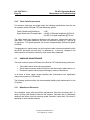
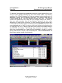
If all is okay, then the sonar image display will appear and the sonar head will begin
scanning.
4.4.18 Completing Trawl Unit Assembly
The final step in the installation is to complete the trawl unit assembly and mount it
to the headrope as shown on drawings in Chapter 7.
First, the plastic cable strain relief supplied with the trawl unit must be bolted to the
trawl cable. The location should be at or very near the pigtail splice, but NOT on the
pigtail itself. You must slide the rubber hose on the trawl cable, if used, down so
that approximately 3-4 cm (1-2") of the hose is clamped inside the strain relief.
Next, the trawl cable is connected to the sonar head. Liberal amounts of Dow Corning
#55 grease are applied to the connector surfaces before mating so that a water tight
seal is obtained. The locking sleeve is then hand-tightened.
Note!
Dow Corning #55 grease must be applied to all mating surfaces of
underwater connectors to insure proper sealing. Sufficient grease
should be applied so that excess squeezes out with any air when the
connectors are mated. RTV or any other sealant must NOT be used,
and when tightening the locking sleeves do NOT use a wrench or
pliers! See chapter 5, "Troubleshooting and Maintenance", for proper
connector maintenance.
Kongsberg Simrad Mesotech Ltd.
Port Coquitlam, BC - Canada