1
TECH SHEET - DO NOT DISCARD
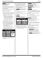
Power Cord
Plug
N
L1
4. Replace the machine control electronics.
Drive Motor
Switch
5. Plug in dryer or reconnect power.
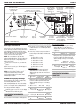
6. Perform steps under DIAGNOSTIC: Console
Buttons and Indicators, page 1, to verify repair.
1
White
Connector
TEST #3 Motor Circuit
264 3 5
If there is no continuity, disconnect the white
wire of the harness from the power cord at
the location illustrated in figure 5, page 4.
Test the continuity of the power cord neutral
wire as illustrated in figure 6. If an open
circuit is found, replace the power cord.
Otherwise, go to step 6.
PAGE 5
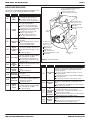
This test will check the wiring to the motor and the
motor itself. The following items are part of this
motor system:
COM
N
Part of Motor System
L1
G
Electric
Dryer
Harness/connection
Thermal fuse
G
Figure 6. Power cord terminals, gas dryer.
Gas
Dryer
no
Belt/belt switch
Drive motor
Centrifugal switch
6. In a similar way, check the continuity between
the L1 terminal of the plug and P9-2 (black
wire) on the control board.
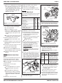
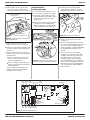
Figure 8. Remove white connector.
Door switch
Machine control electronics. See
ESD information, page 1.
6. Remove the bare copper wire terminal from
pin 5 of black drive motor switch. See figure 9.
Main Winding:
Lt. Blue Wire in Back
and Bare Copper Wire
If there is continuity, go to step 8.
If an open circuit is found, replace the power
cord. Otherwise, replace the main harness.
1. Unplug dryer or disconnect power.
2. Access the machine control electronics and
measure the resistance across P8-4 and P9-1.
See Accessing & Removing the Electronic
Assemblies, page 9.
If resistance across P8-4 and P9-1 is in the
range of 1 to 6 Ω, replace the machine
control electronics.
7. Visually check that the P2 connector is
inserted all the way into the machine control
electronics.
8. Visually check that the console electronics and
housing assembly is properly inserted into the
front console.
9. If both visual checks pass, replace the console
electronics and housing assembly.
Otherwise, go to step 3.
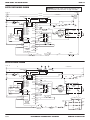
3. Check the wiring and components in the path
between these measurement points by
referring to the appropriate wiring diagram
(gas or electric) on page 12.
ELECTRIC DRYER ONLY: Check the thermal
fuse. See TEST #4b, page 7.
10. Plug in dryer or reconnect power.
ALL DRYERS: Continue with step 4 below to
test the remaining components in the motor
circuit.
11. Perform steps under DIAGNOSTIC: Console
Buttons and Indicators, page 1, to verify repair.
12. If indicators still do not light, perform
TEST #2.
TEST #2 Machine Control Power
Check
This test is used to determine if power is present
at the machine control electronics. This test
assumes that TEST #1 has been completed.
Start
Winding:
Lt. Blue Wire
in Back and
Bare Copper
Wire
5 1
26 4 3
If there is no continuity, check the continuity
of the power cord in a similar way to that
illustrated in figure 6, but for power cord’s
L1 wire.
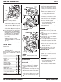
4. Check the belt switch and drive motor. Access
the belt switch and drive motor by removing
the back panel. See Removing the Back Panel,
page 11. Slowly remove the drum belt from the
spring-loaded belt switch pulley, gently letting
the belt switch pulley down. See figure 7.
Figure 9. Main and start winding measure
points.
7. Using figure 9, check for the resistance values
of the motor’s Main and Start winding coils as
shown in the following table.
NOTE: Main and Start winding coils must be
checked at the motor.
Winding Resistance
MAIN
3.3–3.6
Lt. blue wire in back at
pin 4 and bare copper wire
terminal removed from pin 5
of black drive motor switch
2.7–3.0
Lt. blue wire in back at
pin 4 and bare copper wire
terminal on pin 3 of black
drive motor switch
Belt Switch Pulley
START
NOTE: The drum light is controlled by the machine
control on all models.
Contact Points
of Measurement
1. Plug in dryer or reconnect power.
If the resistance at the motor is correct,
there is an open circuit between the motor
and machine control electronics. Check
for failed belt switch.
2. Open the door.
If the drum light illuminates, then power is
present at the machine control. Go to
step 3.
If the drum light fails to illuminate, the
problem may be as simple as a bad bulb.
Replace bulb with a working bulb. If drum
light still fails to illuminate, continue with
step 3.
3. Unplug dryer or disconnect power.
Drum
Belt
Figure 7. Slowly remove drum belt.
5. Remove the white connector from the drive
motor switch. See figure 8.
FOR SERVICE TECHNICIAN’S USE ONLY
If the Start winding resistance is much
greater than 3 Ω, replace the motor.
8. Check the belt switch by measuring resistance
between the two light blue wires, as shown in
figure 10, page 6, while pushing up the belt
switch pulley.
PART NO. W10258368B