1
Agilent 75000 Series B
Agilent E1330B
Quad 8-Bit Digital I/O Module
User’s Manual and SCPI Programming Guide
Where to Find it - Online and Printed Information:
System installation (hardware/software) ............VXIbus Configuration Guide*
Agilent VIC (VXI installation software)*
Module configuration and wiring .......................This Manual
SCPI programming ............................................. This Manual
SCPI example programs .....................................This Manual, Driver Disk
SCPI command reference ..................................This Manual
Register-Based Programming.............................This Manual
VXIplug&play programming ............................ VXIplug&play Online Help
VXIplug&play example programs .....................VXIplug&play Online Help
VXIplug&play function reference......................VXIplug&play Online Help
Soft Front Panel information ..............................VXIplug&play Online Help
VISA language information................................Agilent VISA User's Guide
Agilent VEE programming information.............Agilent VEE User's Manual
*Supplied with Agilent Command Modules, Embedded Controllers, and VXLink.
*E1330-90007*
Manual Part Number: E1330-90007
Printed in Malaysia E0606
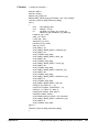
Contents
Agilent E1330B User’s Manual
Warranty ....................................................................................................................... 5
Safety Symbols ............................................................................................................. 6
WARNINGS ................................................................................................................. 6
Declaration of Conformity ............................................................................................ 7
User Notes..................................................................................................................... 8
Chapter 1
Getting Started ............................................................................................................. 11
Using This Chapter ..................................................................................................... 11
Technical Description ................................................................................................. 11
Instrument Definition.................................................................................................. 13
Downloading SCPI Drivers ........................................................................................ 13
Programming the Digital I/O Module......................................................................... 13
SCPI Command Format Used in This Manual .................................................... 14
Specifying SCPI Commands ............................................................................... 14
Initial Operation .......................................................................................................... 16
Chapter 2
Configuring the Agilent E1330B Digital I/O Module ............................................... 17
Using This Chapter ..................................................................................................... 17
Setting the Address Switch ......................................................................................... 18
Enabling Pull-ups........................................................................................................ 19
Selecting the Interrupt Line ........................................................................................ 20
Combining the Flag Lines........................................................................................... 21
Digital I/O Module Peripheral Pinout......................................................................... 22
Configuring for Isolated Digital I/O ........................................................................... 25
Connecting to a GPIO Peripheral ............................................................................... 26
Using with External Pull-ups ...................................................................................... 28
Typical Connection..................................................................................................... 29
Chapter 3
Using the Agilent E1330B Digital I/O Module .......................................................... 31
Using This Chapter ..................................................................................................... 31
Addressing the Module ............................................................................................... 31
Operation Overview.................................................................................................... 32
Default and Reset States ............................................................................................. 33
Setting the Polarity...................................................................................................... 33
Setting the Handshake Mode ...................................................................................... 34
Handshake Timing .............................................................................................. 34
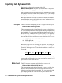
Inputting Data Bytes and Bits ..................................................................................... 35
Input .................................................................................................................... 35
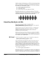
Outputting Data Bytes and Bits .................................................................................. 36
Output .................................................................................................................. 36
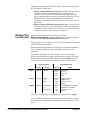
Multiple Port Operations ............................................................................................ 37
Using Trace Memory .................................................................................................. 38
Contents
1
Chapter 4
Understanding the Agilent E1330B Digital I/O Module .......................................... 41
Using This Chapter ..................................................................................................... 41
Port Description .......................................................................................................... 41
Data Lines ........................................................................................................... 41
The FLG Line (Input) .......................................................................................... 42
The CTL Line (Output) ....................................................................................... 42
The I/O Line (Output) ......................................................................................... 42
The STS Line ...................................................................................................... 43
The PIR Line ....................................................................................................... 43
The RES Line ...................................................................................................... 43
Default and Reset States ............................................................................................. 43
Setting the Polarity...................................................................................................... 43
Using the Handshake Modes ...................................................................................... 44
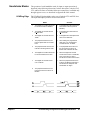
Handshake Modes ............................................................................................... 45
Inputting Data Bytes and Bits ..................................................................................... 50
Bit Input ............................................................................................................... 50
Byte Input ............................................................................................................ 50
Outputting Data Bytes and Bits .................................................................................. 51
Bit Output ............................................................................................................ 51
Byte Output ......................................................................................................... 52
Multiple Port Operations ............................................................................................ 53
Multiple Port Handshaking ................................................................................. 53
Multiple Port Input/Output .................................................................................. 54
Chapter 5
Agilent E1330B Digital I/O Module Command Reference ...................................... 57
Using This Chapter ..................................................................................................... 57
Command Types ......................................................................................................... 57
Common Command Format ................................................................................ 57
SCPI Command Format ...................................................................................... 57
Linking Commands ............................................................................................. 59
SCPI Command Reference ......................................................................................... 60
DISPlay Subsystem..................................................................................................... 61
:MONitor:PORT .................................................................................................. 61
:MONitor:PORT? ................................................................................................ 62
:MONitor[:STATe] ............................................................................................. 62
:MONitor[:STATe]? ............................................................................................ 63
MEASure Subsystem .................................................................................................. 64
:DIGital:DATAn[:type]:BITm? .......................................................................... 64
:DIGital:DATAn[:type]:TRACe ......................................................................... 65
:DIGital:DATAn[:type][:VALue]? ..................................................................... 66
:DIGital:FLAGn? ................................................................................................ 67
MEMory Subsystem ................................................................................................... 68
:DELete:MACRo ................................................................................................ 68
:VME:ADDRess .................................................................................................. 69
:VME:ADDRess? ................................................................................................ 69
:VME:SIZE ......................................................................................................... 70
2
Contents
Chapter 5
Agilent E1330B Digital I/O Module Command Reference (continued)
MEMory Subsystem (continued)
:VME:SIZE? ........................................................................................................ 70
:VME:STATe ...................................................................................................... 71
:VME:STATe? .................................................................................................... 71
[SOURce:] Subsystem ................................................................................................ 72
DIGital:CONTroln:POLarity .............................................................................. 74
DIGital:CONTroln:POLarity? ............................................................................ 74
DIGital:CONTroln[:VALue] .............................................................................. 75
DIGital:CONTroln[:VALue]? ............................................................................. 75
DIGital:DATAn[:type]:BITm ............................................................................. 76
DIGital:DATAn[:type]:BITm? ............................................................................ 77
DIGital:DATAn[:type]:HANDshake:DELay ..................................................... 78
DIGital:DATAn[:type]:HANDshake:DELay? .................................................... 79
DIGital:DATAn[:type]:HANDshake[:MODE] .................................................. 80
DIGital:DATAn[:type]:HANDshake[:MODE]? ................................................. 81
DIGital:DATAn[:type]:POLarity ........................................................................ 82
DIGital:DATAn[:type]:POLarity? ...................................................................... 82
DIGital:DATAn[:type]:TRACe .......................................................................... 83
DIGital:DATAn[:type][:VALue] ........................................................................ 84
DIGital:DATAn[:type][:VALue]? ...................................................................... 85
DIGital:FLAGn:POLarity ................................................................................... 86
DIGital:FLAGn:POLarity? ................................................................................. 86
DIGital:HANDshaken:DELay ............................................................................ 87
DIGital:HANDshaken:DELay? .......................................................................... 88
DIGital:HANDshaken[:MODE] ......................................................................... 88
DIGital:HANDshaken[:MODE]? ........................................................................ 89
DIGital:IOn? ........................................................................................................ 89
DIGital:TRACe:CATalog? ................................................................................. 90
DIGital:TRACe[:DATA] .................................................................................... 90
DIGital:TRACe[:DATA]? .................................................................................. 91
DIGital:TRACe:DEFine ...................................................................................... 91
DIGital:TRACe:DEFine? .................................................................................... 92
DIGital:TRACe:DELete:ALL ............................................................................. 92
DIGital:TRACe:DELete[:NAME] ...................................................................... 92
STATus Subsystem..................................................................................................... 93
:OPERation:CONDition? .................................................................................... 94
:OPERation:ENABle ........................................................................................... 94
:OPERation:ENABle? ......................................................................................... 94
:OPERation[:EVENt]? ........................................................................................ 94
:PRESet ............................................................................................................... 94
:QUEStionable:CONDition? ............................................................................... 95
:QUEStionable:ENABle ...................................................................................... 95
:QUEStionable:ENABle? .................................................................................... 95
:QUEStionable[:EVENt]? ................................................................................... 95
Contents
3
Chapter 5 (continued)
SYSTem Subsystem ................................................................................................... 96
:CDEScription? ................................................................................................... 96
:CTYPe? .............................................................................................................. 96
:ERRor? ............................................................................................................... 97
:VERSion? ........................................................................................................... 97
IEEE 488.2 Common Commands............................................................................... 98
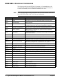
Command Quick Reference........................................................................................ 99
Appendix A
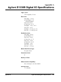
Agilent E1330B Digital I/O Specifications ............................................................... 103
Appendix B
Agilent E1330B Digital I/O Module Register Information .................................... 105
Using This Appendix ................................................................................................ 105
Addressing the Registers .......................................................................................... 105
The Base Address .............................................................................................. 106
Register Offset ................................................................................................... 108
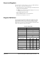
Reset and Registers ................................................................................................... 109
Register Definitions .................................................................................................. 109
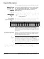
Register Descriptions ................................................................................................ 111
Manufacturer Identification Register ................................................................ 111
Device Identification Register ........................................................................... 111
Card Status/ Control Register ............................................................................ 111
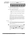
Port Interrupt Control Register .......................................................................... 112
Port Transfer Control Register .......................................................................... 113
Port Control/ Status Register ............................................................................. 114
Port Data Register ............................................................................................. 115
Port Handshake Register ................................................................................... 116
Port Delay Register ........................................................................................... 117
Port Normalization Register .............................................................................. 118
A Register-Based Output Algorithm ........................................................................ 119
A Register-Based Input Algorithm ........................................................................... 120
Programming Examples............................................................................................ 121
System Configuration ........................................................................................ 121
Resetting the Module ........................................................................................ 122
Reading the ID, Device Type, and Status Registers ......................................... 123
Writing an 8-Bit Byte ........................................................................................ 125
Writing a 16-Bit Word ...................................................................................... 127
Reading an 8-Bit Byte ....................................................................................... 128
Reading a 16-Bit Word ..................................................................................... 130
Debugging Basic Register-Based Programs ..................................................... 130
PIR Interrupts on the Agilent E1330 ................................................................. 131
Agilent E1330B Non-data Line I/O .................................................................. 136
Embedded Computer Example .......................................................................... 140
Appendix C
Error Messages .......................................................................................................... 143
4
Contents
Certification
Agilent Technologies, Inc. certifies that this product met its published specifications at the time of shipment from the factory. Agilent
Technologies further certifies that its calibration measurements are traceable to the United States National Institute of Standards and
Technology (formerly National Bureau of Standards), to the extent allowed by that organization's calibration facility, and to the
calibration facilities of other International Standards Organization members.
AGILENT TECHNOLOGIES WARRANTY STATEMENT
PRODUCT:
E1330B
DURATION OF WARRANTY: 1 year
1. Agilent warrants Agilent hardware, accessories and supplies against defects in materials and workmanship for the period specified
above (one year). If Aglent receives notice of such defects during the warranty period, Agilent will, at its option, either repair or replace
products which prove to be defective. Replacement products may be either new or like-new.
2. Agilent warrants that Agilent software will not fail to execute its programming instructions, for the period specified above, due to
defects in material and workmanship when properly installed and used. If Agilent receives notice of such defects during the warranty
period, Agilent will replace software media which does not execute its programming instructions due to such defects.
3. Agilent does not warrant that the operation of Agilent products will be interrupted or error free. If Agilent is unable, within a reasonable
time, to repair or replace any product to a condition as warranted, customer will be entitled to a refund of the purchase price upon prompt
return of the product.
4. Agilent products may contain remanufactured parts equivalent to new in performance or may have been subject to incidental use.
5. The warranty period begins on the date of delivery or on the date of installation if installed by Agilent. If customer schedules or delays
Agilent installation more than 30 days after delivery, warranty begins on the 31st day from delivery.
6. Warranty does not apply to defects resulting from (a) improper or inadequate maintenance or calibration, (b) software, interfacing, parts
or supplies not supplied by Agilent Technologies, (c) unauthorized modification or misuse, (d) operation outside of the published
environmental specifications for the product, or (e) improper site preparation or maintenance.
7. TO THE EXTENT ALLOWED BY LOCAL LAW, THE ABOVE WARRANTIES ARE EXCLUSIVE AND NO OTHER
WARRANTY OR CONDITION, WHETHER WRITTEN OR ORAL, IS EXPRESSED OR IMPLIED AND AGILENT
SPECIFICALLY DISCLAIMS ANY IMPLIED WARRANTY OR CONDITIONS OF MERCHANTABILITY, SATISFACTORY
QUALITY, AND FITNESS FOR A PARTICULAR PURPOSE.
8. Agilent will be liable for damage to tangible property per incident up to the greater of $300,000 or the actual amount paid for the product
that is the subject of the claim, and for damages for bodily injury or death, to the extent that all such damages are determined by a court
of competent jurisdiction to have been directly caused by a defective Agilent product.
9. TO THE EXTENT ALLOWED BY LOCAL LAW, THE REMEDIES IN THIS WARRANTY STATEMENT ARE CUSTOMER’S
SOLE AND EXLUSIVE REMEDIES. EXCEPT AS INDICATED ABOVE, IN NO EVENT WILL AGILENT OR ITS SUPPLIERS BE
LIABLE FOR LOSS OF DATA OR FOR DIRECT, SPECIAL, INCIDENTAL, CONSEQUENTIAL (INCLUDING LOST PROFIT OR
DATA), OR OTHER DAMAGE, WHETHER BASED IN CONTRACT, TORT, OR OTHERWISE.
FOR CONSUMER TRANSACTIONS IN AUSTRALIA AND NEW ZEALAND: THE WARRANTY TERMS CONTAINED IN THIS
STATEMENT, EXCEPT TO THE EXTENT LAWFULLY PERMITTED, DO NOT EXCLUDE, RESTRICT OR MODIFY AND ARE
IN ADDITION TO THE MANDATORY STATUTORY RIGHTS APPLICABLE TO THE SALE OF THIS PRODUCT TO YOU.
U.S. Government Restricted Rights
The Software and Documentation have been developed entirely at private expense. They are delivered and licensed as "commercial
computer software" as defined in DFARS 252.227- 7013 (Oct 1988), DFARS 252.211-7015 (May 1991) or DFARS 252.227-7014 (Jun
1995), as a "commercial item" as defined in FAR 2.101(a), or as "Restricted computer software" as defined in FAR 52.227-19 (Jun
1987)(or any equivalent agency regulation or contract clause), whichever is applicable. You have only those rights provided for such
Software and Documentation by the applicable FAR or DFARS clause or the Agilent standard software agreement for the product
involved.
IEC Measurement Category II Overvoltage Protection
This is a measurement Category II product designed for measurements at voltages up to 300V from earth, including measurements of
voltages at typical mains socket outlets. The product should not be used to make voltage measurements on a fixed electrical installation
including building wiring, circuit breakers, or service panels.
E1330B Quad 8-Bit Digital I/OModule User's Manual
Edition 7 Rev 2
Copyright © 1997-2006 Agilent Technologies, Inc. All Rights Reserved.
5
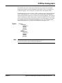
Documentation History
All Editions and Updates of this manual and their creation date are listed below. The first Edition of the manual is Edition 1. The Edition
number increments by 1 whenever the manual is revised. Updates, which are issued between Editions, contain replacement pages to
correct or add additional information to the current Edition of the manual. Whenever a new Edition is created, it will contain all of the
Update information for the previous Edition. Each new Edition or Update also includes a revised copy of this documentation history page.
Edition 1 . . . . . . . . . . . . . . . . . . . . . . . . . . . . . . . . . . . . . . . . . .
Edition 2 . . . . . . . . . . . . . . . . . . . . . . . . . . . . . September 1990
Edition 3 . . . . . . . . . . . . . . . . . . . . . . . . . . . . . . . . . April 1992
Edition 4 . . . . . . . . . . . . . . . . . . . . . . . . . . . . . September 1992
Edition 5 . . . . . . . . . . . . . . . . . . . . . . . . . . . . . November 1993
Edition 6 . . . . . . . . . . . . . . . . . . . . . . . . . . . . . . . . . . June 1995
Edition 7 (Part Number E1330-90007) . . . . . . . . . . .May 1997
Edition 7 Rev 2 (Part Number E1330-90007) . . . . . .June 2006
Safety Symbols
Instruction manual symbol affixed to
product. Indicates that the user must refer to
the manual for specific WARNING or
CAUTION information to avoid personal
injury or damage to the product.
Alternating current (AC)
Direct current (DC).
Indicates hazardous voltages.
Indicates the field wiring terminal that must
be connected to earth ground before
operating the equipment—protects against
electrical shock in case of fault.
or
Frame or chassis ground terminal—typically
connects to the equipment's metal frame.
Calls attention to a procedure, practice, or
WARNING condition that could cause bodily injury or
death.
Calls attention to a procedure, practice, or
CAUTION condition that could possibly cause damage to
equipment or permanent loss of data.
WARNINGS
The following general safety precautions must be observed during all phases of operation, service, and repair of this product. Failure to
comply with these precautions or with specific warnings elsewhere in this manual violates safety standards of design, manufacture, and
intended use of the product. Agilent Technologies, Inc. assumes no liability for the customer's failure to comply with these requirements.
Ground the equipment: For Safety Class 1 equipment (equipment having a protective earth terminal), an uninterruptible safety earth
ground must be provided from the mains power source to the product input wiring terminals or supplied power cable.
DO NOT operate the product in an explosive atmosphere or in the presence of flammable gases or fumes.
For continued protection against fire, replace the line fuse(s) only with fuse(s) of the same voltage and current rating and type. DO NOT
use repaired fuses or short-circuited fuse holders.
Keep away from live circuits: Operating personnel must not remove equipment covers or shields. Procedures involving the removal of
covers or shields are for use by service-trained personnel only. Under certain conditions, dangerous voltages may exist even with the
equipment switched off. To avoid dangerous electrical shock, DO NOT perform procedures involving cover or shield removal unless you
are qualified to do so.
DO NOT operate damaged equipment: Whenever it is possible that the safety protection features built into this product have been
impaired, either through physical damage, excessive moisture, or any other reason, REMOVE POWER and do not use the product until
safe operation can be verified by service-trained personnel. If necessary, return the product to an Agilent Technologies Sales and Service
Office for service and repair to ensure that safety features are maintained.
DO NOT service or adjust alone: Do not attempt internal service or adjustment unless another person, capable of rendering first aid and
resuscitation, is present.
DO NOT substitute parts or modify equipment: Because of the danger of introducing additional hazards, do not install substitute parts
or perform any unauthorized modification to the product. Return the product to an Agilent Technologies Sales and Service Office for
service and repair to ensure that safety features are maintained.
6
DECLARATION OF CONFORMITY
According to ISO/IEC Guide 22 and CEN/CENELEC EN 45014
Manufacturer’s Name:
Manufacturer’s Address:
Agilent Technologies, Incorporated
th
815 – 14 St. SW
Loveland, Colorado 80537
USA
Declares, that the product
Product Name:
Model Number:
Product Options:
Quad 8 Bit Digital I/O
E1330B
This declaration covers all options of the above product(s).
Conforms with the following European Directives:
The product herewith complies with the requirements of the Low Voltage Directive 73/23/EEC and the EMC Directive 89/336/EEC
(including 93/68/EEC) and carries the CE Marking accordingly.
Conforms with the following product standards:
EMC
Standard
Limit
IEC 61326-1:1997+A1:1998 / EN 61326-1:1997+A1:1998
CISPR 11:1990 / EN 55011:1991
IEC 61000-4-2:1995+A1:1998 / EN 61000-4-2:1995
IEC 61000-4-3:1995 / EN 61000-4-3:1995
IEC 61000-4-4:1995 / EN 61000-4-4:1995
IEC 61000-4-5:1995 / EN 61000-4-5:1995
IEC 61000-4-6:1996 / EN 61000-4-6:1996
IEC 61000-4-11:1994 / EN 61000-4-11:1994
Group 1 Class A
4kV CD, 8kV AD
3 V/m, 80-1000 MHz
0.5kV signal lines, 1kV power lines
0.5 kV line-line, 1 kV line-ground
3V, 0.15-80 MHz I cycle, 100%
Dips: 30% 10ms; 60% 100ms
Interrupt > 95%@5000ms
Canada: ICES-001:1998
Australia/New Zealand: AS/NZS 2064.1
The product was tested in a typical configuration with Agilent Technologies test systems.
Safety
IEC 61010-1:1990+A1:1992+A2:1995 / EN 61010-1:1993+A2:1995
Canada: CSA C22.2 No. 1010.1:1992
UL 3111-1: 1994
1 June 2001
Date
Ray Corson
Product Regulations Program Manager
For further information, please contact your local Agilent Technologies sales office, agent or distributor.
Authorized EU-representative: Agilent Technologies Deutschland GmbH, Herrenberger Straβe 130, D 71034 Böblingen, Germany
7
Notes:
8
Notes:
9
Notes:
10
Chapter 1
Getting Started
Using This Chapter
This chapter describes the Quad 8-bit Digital I/O Module and how to
program the Module using SCPI (Standard Commands for Programmable
Instruments) commands. This chapter contains the following sections:
• Technical Description . . . . . . . . . . . . . . . . . . . . . . . . . . . . . .
• Instrument Definition . . . . . . . . . . . . . . . . . . . . . . . . . . . . . .
• Downloading SCPI Drivers . . . . . . . . . . . . . . . . . . . . . . . . .
• Programming the Digital I/O Module . . . . . . . . . . . . . . . . . .
• Initial Operation . . . . . . . . . . . . . . . . . . . . . . . . . . . . . . . . . .
Page 11
Page 13
Page 13
Page 13
Page 16
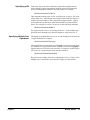
Technical Description
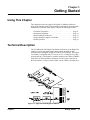
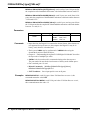
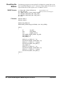
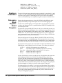
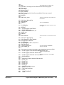
The E1330B Quad 8-Bit Digital I/O Module (referred to as the Digital I/O
module) is a four port digital input/output module intended for data
communication and digital control in electronic environments. The Digital
I/O module is compatible with TTL levels (0-5V) or CMOS levels (using
external pull-ups). The Digital I/O module complies with VXIbus (VMEbus
Extensions for Instrumentation) definitions for the P1 bus connector on
B-sized modules. A jumper on the module sets the VXIbus interrupt level.
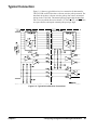
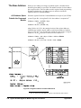
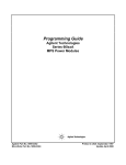
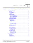
Figure 1-1. Agilent E1330B Digital I/O Module
Chapter 1
Getting Started
11
Each port is identical and consists of 6 control lines and 8 data lines. There
are 7 registers for control and status on each port. In addition, the module
also has Manufacturer ID, Device Type, and Module Status/Control
Registers. Figure 1-1 shows the locations of the ports and a simplified
diagram of a single port. Of the seven control lines, three (I/O, CTL, and
FLG) are used with SCPI commands and three (RES, STS, and PIR) are
controlled through register access. Chapter 4 — “Understanding the
Agilent E1330B Digital I/O Module” contains detailed descriptions of these
lines.
Each port has two sets of hardware configuration jumpers. One set of
jumpers allows you to connect the FLG lines together for multi-port data
transmission. Another jumper selects either open collector operation or
internal pull-up to TTL compatible levels on the data lines. Chapter 2 —
“Configuring the Agilent E1330B Digital I/O Module” describes how to set
these jumpers.
SCPI commands provided for the Digital I/O allow operation on a single bit,
8-bit "BYTE" format, 16-bit "WORD" format (using 2 ports), or 32-bit
"LWORd" format (using 4 ports).
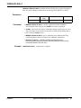
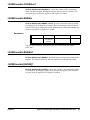
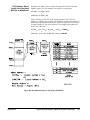
Table 1-1 shows the mapping of bit numbers from the 8-bit ports to the
16- or 32-bit ports. Chapter 5 — “Agilent E1330B Digital I/O Command
Reference” describes each command in detail and Chapter 3 — “Using the
Agilent E1330B Digital I/O Module” gives examples of the use of SCPI
commands.
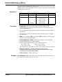
Table 1-1. Data Lines
8-bit (BYTE) Operations
Port #
Bit designations
0
1
2
3
7------0
7------0
7------0
7------0
16-bit (WORD) Operations
Port #
Bit designations
0
15------8
2
7------0
15------8
7------0
15------8
7------0
32-bit (LWORd) Operations
Port #
Bit designations
0
31------24
23------16
Two 3-meter, 60-wire ribbon cables with an insulation displacement header
connector (ribbon cable connector) on one end are included with the Digital
I/O module. Additional cable sets can be ordered (Agilent part number
E1330-61601) from your nearest Agilent Technologies Sales Office.
12
Getting Started
Chapter 1
Instrument Definition
Each Digital I/O module installed in an Agilent mainframe is treated as an
independent instrument; having a unique secondary GPIB address. Each
instrument is also assigned a dedicated error queue, input and output buffers,
status registers and, if applicable, dedicated mainframe memory space for
readings or data. Multiple Digital I/O modules cannot be combined into a
single instrument.
Downloading SCPI Drivers
The Agilent Digital I/O Driver allows the Agilent E1330B module to
operate with either B-size mainframes or Agilent E1405/06 Command
Modules in a C-size mainframe. The driver implements the Standard
Commands for Programmable Instrumentation (SCPI) command language.
The B-size Agilent E1300/E1301 Mainframe has a built in driver, or can use
a downloadable driver. The two drivers are slightly different and the
differences are detailed in Chapter 5 — “Agilent E1330B Digital I/O
Command Reference”.
To use the Agilent E1330B with a C-size mainframe and command module,
you must use a downloadable driver. The downloadable driver name for the
Digital I/O module is “DIG_IO”. The procedure for downloading the drivers
is contained in the Agilent E1405B and Agilent E1406A Command Module
User Guides.
Programming the Digital I/O Module
To program the Digital I/O module using SCPI commands, you will need to
know the controller language and interface addresses you will be using. See
the Agilent 75000 Series B or Series C Installation and Getting Started
Guide for detailed interface addressing and controller language information.
Note
Chapter 1
This discussion applies only to SCPI (Standard Commands for
Programmable Instruments) programming. See Appendix B — “Digital I/O
Register Information” for details on register addressing. Do not mix SCPI
programming and direct register access.
Getting Started
13
SCPI Command
Format Used in This
Manual
SCPI commands can be used in either long or short form. A long form
example is:
DISPlay:MONitor ON
The same command, without the lower case letters, is the short form.
For example:
DISP:MON ON
Either the long form or the short form commands can be used to perform the
same result. The long and short forms can also be mixed within the same
program code. The commands are case insensitive, either upper or lower
case letters are accepted.
In the command examples shown above, the item enclosed in <> is a
parameter required to use the command, however, do not include the
brackets when sending the command. In this example, the parameter input
can be replaced with any one of the following: 0, 1, OFF, or ON. The
allowable values of the parameters are given in Chapter 5 — “Agilent
E1330B Digital I/O Module Command Reference”. You must include at
least one space between the keywords and the parameter.
Some commands are shown with items enclosed in square brackets ([]).
These are implied or optional items that do not have to be included. For
example, the complete command syntax listing for the first example is:
DISPlay:MONitor[:STATe] <0 |1 or OFF|ON>
The item enclosed in brackets, [:STATe], does not have to be included for the
command to work. Complete descriptions of the SCPI command language,
syntax, parameter types, and usage are in Chapter 5 of this manual.
Specifying SCPI
Commands
SCPI commands related to the Digital I/O module use three types of
parameters to specify a port number, a bit number, or a multiple port
combining operation. Each type is briefly described here. Descriptions and
examples of usage can be found in Chapter 3 of this manual.
Specifying a Port
The Digital I/O module has four identical ports numbered from 0 to 3. SCPI
commands that relate to a specific port use a special parameter to indicate
the port number. For example:
[SOURce:]DIGital:DATA n <value>
This command writes the parameter <value> to the port specified by the n
portion of the DATA keyword. Replace the n with the port number, making
the number the last character of the DATA keyword without spaces. For
example, to set all port 2 data lines to logical zero, use the command:
[SOURce:]DIGital:DATA2 0
The value of n may vary for multiple port commands and operations. A
description of multiple port commands is on page 15.
14
Getting Started
Chapter 1
Specifying a Bit
Each of the four ports on the module has eight bi-directional data lines,
corresponding to eight programmable data bits. Some SCPI commands
allow you manipulate or read these bits individually. For example:
MEASure:DIGital:DATAn:BITm?
This command reads the state of a bit, specified by m, on port n. The result
will be either 0 or 1, indicating the current logical state of the bit. Replace m
with the desired bit number, and n with the desired port number, making
each number the last characters of the DATA and BIT keywords without
spaces. For example, to read bit 7 on port 0, use the following command:
MEASure:DIGital:DATA0:BIT7?
For single ports, the value of m can range from 0 to 7. Some multiple port
operations and commands may allow bit numbers to range from 0 to 31.
Specifying Multiple Port
Operations
The Digital I/O module allows you to set or read multiple ports or bits with
a single command. For example:
MEASure:DIGital:DATAn[:type]?
This command uses an optional keyword, [:type], to specify how many ports
are combined in a single returned value. The lower case keyword [:type] is
replaced with one of a fixed set of keywords. For example, to read all 4 ports
(all 32-bits) as a single returned value, use the command:
MEASure:DIGital:DATA0:LWORd?
Keywords are provided to allow port combinations of 16- or 32-bits. Using
multiple ports is described in more detail in Chapter 4 of this manual.
Chapter 1
Getting Started
15
Initial Operation
Use the following example to verify initial operation. The example first sets
and then queries the polarity of a logical true condition on the port 0 FLG
line. The example uses an HP Series 200/300 Computer with BASIC as the
programming language. The computer is connected to an Agilent E1301
Mainframe using the General Purpose Interface Bus (GPIB)*. The GPIB
interface select code is 7, the GPIB primary address is 09, and the GPIB
secondary address (used to specify the Digital I/O module) is 18. Refer to
the B-Size Installation and Getting Started Guide for more details.
10
20
30
40
50
60
70
80
90
100
110
120
130
140
150
160
170
180
190
200
210
220
230
240
250
260
270
280
290
ASSIGN @Dio TO 70918
DIM Polarity$[3]
OUTPUT @Dio;"*RST"
OUTPUT @Dio;"*OPC?"
ENTER @Dio;Ready
!Sets an I/O path to the module.
!Reset the module.
!Wait for the module to finish.
!Hold here until command is
finished.
OUTPUT @Dio;"SOUR:DIG:FLAG0:POL POS;*OPC?"
!Set POSitive polarity.
ENTER @Dio;Ready
!Wait for finish.
OUTPUT @Dio;"SOUR:DIG:FLAG0:POL?"
!Query the polarity state.
ENTER @Dio;Polarity$
!Get the result.
IF Polarity$ <> "POS" THEN
!Check the result.
DISP "Polarity Check ERROR"
!Error discovered.
PAUSE
!Pause on error.
ELSE
DISP"Polarity set to "&Polarity$
END IF
OUTPUT @Dio;"SOUR:DIG:FLAG0:POL NEG;*OPC?"
!Set NEGative polarity.
ENTER @Dio;Ready
!Wait for finish.
OUTPUT @Dio;"SOUR:DIG:FLAG0:POL?"
!Query the polarity state.
ENTER @Dio;Polarity$
!Get the result.
IF Polarity$ <> "NEG" THEN
!Check the result.
DISP "Polarity Check ERROR"
!Error discovered.
PAUSE
!Pause on error.
ELSE
DISP"Polarity set to "&Polarity$
END IF
OUTPUT @Dio;"*RST"
!Restore the module.
OUTPUT @Dio;"*OPC?"
!Wait for the module to finish.
ENTER @Dio;Ready
END
* GPIB is the implementation of IEEE Std 488.1-1984.
16
Getting Started
Chapter 1
Chapter 2
Configuring the Agilent E1330B Digital I/O
Module
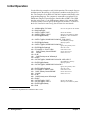
Using This Chapter
This chapter shows how to configure the Digital I/O module for use in a
VXIbus mainframe, connect peripheral devices, and configure the module
for operation. Refer to Figure 2-1 for locations of jumpers and switches. This
chapter contains the following sections:
• Setting the Address Switch . . . . . . . . . . . . . . . . . . . . . . . . . .
• Enabling Pull-ups . . . . . . . . . . . . . . . . . . . . . . . . . . . . . . . . .
• Selecting the Interrupt Line. . . . . . . . . . . . . . . . . . . . . . . . . .
• Combining the Flag Lines. . . . . . . . . . . . . . . . . . . . . . . . . . .
• Digital I/O Module Peripheral Pinout . . . . . . . . . . . . . . . . . .
• Configuring for Isolated Digital I/O . . . . . . . . . . . . . . . . . . .
• Connecting to a GPIO Peripheral . . . . . . . . . . . . . . . . . . . . .
• Using with External Pull-ups . . . . . . . . . . . . . . . . . . . . . . . .
• Typical Connection . . . . . . . . . . . . . . . . . . . . . . . . . . . . . . . .
Page 18
Page 19
Page 20
Page 21
Page 22
Page 25
Page 26
Page 28
Page 29
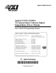
Figure 2-1. Agilent E1330B Digital I/O Module
Chapter 2
Configuring the Agilent E1330B Digital I/O Module
17
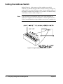
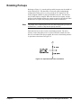
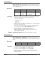
Setting the Address Switch
Refer to Figure 2-1. In the center rear of the module, next to the P1
connector, you will find the logical address switch. Its factory setting is 144;
rockers 4 and 7 are closed, all others are open. You can select the address of
the Digital I/O module to any number 0–255 (decimal). The default setting
of the address switch is shown in Figure 2-2.
Note
To be recognized as an instrument when you are using the Digital I/O
module in an Agilent E1300/1301 Mainframe or with an Agilent E1405 or
E1406 Command Module, the logical address must be set to a multiple of 8.
Figure 2-2. Logical Address Switch Set at 144
18
Configuring the Agilent E1330B Digital I/O
Chapter 2
Enabling Pull-ups
Referring to Figure 2-1, note the pull-up enable jumpers near the middle of
each of the large ICs. The data lines of each port can be independently
configured for either passive or active pull-up to TTL high levels. The
factory-shipped condition is pull-up disabled for all ports. The data lines
may be either inputs or outputs. When the data lines are outputs, and the
jumper is in the enabled position, the outputs are actively forced high. When
the data lines are inputs, the jumper position makes no difference.
Note
The jumper in the enabled position does not add an input pull-up resistor to
each data line, it enables a chip-internal pull-up network.
Each data line has an active resistive terminating network. The active
circuitry ensures that when power is removed from the module, the data
lines are not loaded. With power applied, the resistive terminating network
is equivalent to that shown in Figure 2-3.
Figure 2-3. Equivalent Data Line Termination
Chapter 2
Configuring the Agilent E1330B Digital I/O Module
19
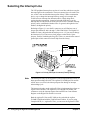
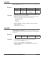
Selecting the Interrupt Line
The VXI peripheral interrupt bus consists of seven lines which can carry the
interrupt signal to the commander. The most common line to be used is line
one, as this is the usual default interrupt line. Many VXIbus commanders
have a way to change the interrupt line they manage (for example, the
E1405/06 has an interrupt line allocation table). When doing direct
register-based programming, instead of using the SCPI driver, set the
interrupt line to a line that is not used by the SCPI driver. Module interrupt
priority can be established with these lines. In general, the higher the line
number, the higher the priority.
Referring to Figure 2-1, near the P1 connector you will find two sets of
jumper pins labeled X and 1 through 7 (JM15 and JM16). The Digital I/O
module is factory-shipped with the interrupt set to 1. If you need to change
the interrupt level you must move both jumpers on the blocks. Spare
jumpers, used for combining the flag (FLG) lines, are stored on the unused
ground pins of this connector when it ships from the factory.
Figure 2-4. Priority Interrupt Connector (Factory Setting)
Note
The interrupt circuitry for the Agilent E1330B is implemented as release on
interrupt acknowledge (ROAK). The Agilent E1330B Digital I/O module
will de-assert (or release) the interrupt request line during an interrupt
acknowledge cycle.
The interrupt circuitry on the Agilent E1330A is implemented as release on
register access (RORA). The Agilent E1330A Digital I/O module will
continue to assert the interrupt request line until the Port Control/Status
Register on the Digital I/O module is accessed.
Both the Agilent E1330A and E1330B can be used with the Agilent
E1300B/E1301B and with the E1405A/B and E1406A. If you are using
Compiled SCPI (i.e., Agilent E1570A), you must use the Agilent E1330B.
20
Configuring the Agilent E1330B Digital I/O
Chapter 2
Combining the Flag Lines
Each port contains a Flag Line, labeled FLG, that can be used to implement
a handshake scheme with a peripheral. For single port operations, the FLG
lines can be used in the factory default setting (no flag lines combined) to
handshake with a peripheral. For multi-port operations with a single
handshake line, you can combine the flag line from multiple ports. The
combined flag lines are physically tied together. An action on any of the
combined flag lines performs that action for all combined flag lines.
Figure 2-5 shows the locations of the flag combining switches and how to
set them. Before setting any flag combine switches, you may wish to read
the discussion regarding allowable port combinations and handshaking in
Chapter 4 of this manual.
Note
When using FLG and CTL for handshaking on multiple port operations,
CTL is set for each port sequentially, beginning at the lowest numbered
port.
Figure 2-5. Flag Combine Switches
Chapter 2
Configuring the Agilent E1330B Digital I/O Module
21
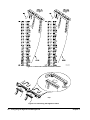
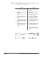
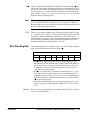
Digital I/O Module Peripheral Pinout
Figure 2-6 shows pinouts for the Digital I/O module connectors. Each is
compatible with easy crimp connections to ribbon cables for standard digital
I/O interfacing. Figure 2-7 shows the data line location on the supplied
ribbon cables. Figure 2-8 shows how to connect the cables. Details about the
functioning of these pins is covered in Chapter 4 — “Understanding the
Agilent E1330B Digital I/O Module but line names are as follows:
22
RES
Reset Line - used to reset a peripheral. Output from the
Digital I/O module.
STS
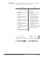
Status Line - used as an auxiliary handshake line. Input
to the Digital I/O module.
PIR
Peripheral Interrupt Line - used to signal a peripheral
interrupt. Input to the Digital I/O module.
FLG
Flag Line - used to handshake data between a
peripheral and the Digital I/O module. Controlled by
the peripheral. Input to the Digital I/O module.
CTL
Control Line - used to handshake data between a
peripheral and the Digital I/O module. Controlled by
the Digital I/O module. Output from the Digital I/O
module.
I/O
Input/Output Line - used to establish input or output
on a port. Controlled by the Digital I/O module. Input
to the Digital I/O module.
Configuring the Agilent E1330B Digital I/O
Chapter 2
Figure 2-6. J1 and J2 Connector Pinouts
Chapter 2
Configuring the Agilent E1330B Digital I/O Module
23
Figure 2-7. Data Line Location on Ribbon Cables
Figure 2-8. Connecting the Digital I/O Cable
24
Configuring the Agilent E1330B Digital I/O
Chapter 2
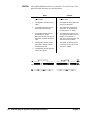
Configuring for Isolated Digital I/O
The two Digital I/O module peripheral connectors, J1 and J2, each have 60
pins. An industry standard isolated digital I/O peripheral, like the Opto 22
16 Position Single Channel Mounting Rack, is a 50-pin connection. The
connector is either a card edge or a header connector (similar to J1 on the
Digital I/O module). For example, the Opto 22 rack, PB16C, uses a card
edge connector; PB16H uses a header connector. They both have the same
pin-out for the ribbon cable. Both can accommodate up to 16 single channel
I/O lines.
12 of the wires on the supplied ribbon cable are not connected. Figure 2-8
shows the ribbon cable connections. The method of connection to the ribbon
cable can be facilitated by the use of specialty fixtures for these connectors,
but there is no standard for connector keys or spacing.
For the Opto 22 rack, lines 1–10 are not used on the peripheral connector.
Pins 27–57 on the ribbon cable, odd numbered pins only, correspond to pins
17–47 on the Opto 22 rack. All even numbered pins are ground. Do not
connect pins 1 and 49 on the Opto 22 rack connector.
Procedure
1. Carefully cut lines 1-11 on the ribbon cable and line 59. A tan wire
should be the first wire on the ribbon cable after you make the cut.
2. Select the 50-pin connector you need, either edge connector or header
connector and attach the ribbon cable.
3. Connect the ribbon cable to the Opto 22 rack for optically isolated
digital operation.
Opto 22 is a registered trademark of Opto 22, Huntington Beach, CA 92649
Chapter 2
Configuring the Agilent E1330B Digital I/O Module
25
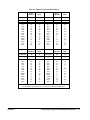
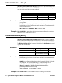
Connecting to a GPIO Peripheral
The GPIO interface is a widely used standard parallel interface for
connecting computers to peripherals. The GPIO interface may employ up to
32-bits of bi-directional data transfer. The Digital I/O module and the GPIO
interface have identical line definitions but different pin assignments.
Ports A-D on the GPIO are defined as ports 0-3 on the Digital I/O module.
Procedure
1. Connect the ribbon cable to connector J1 and/or J2 on the Digital I/O
module.
2. Connect the wires on the ribbon cable to the peripheral as described
in Table 2-1 for the GPIO interface.
Figure 2-9. Typical Isolated Peripheral Hookup
26
Configuring the Agilent E1330B Digital I/O
Chapter 2
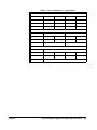
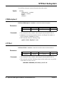
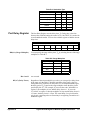
Table 2-1. Digital I/O Pinout to GPIO Pinout
Port 0
Digital I/O
GPIO
Port 1
Digital I/O
GPIO
Connector
J1
J2
Connector
J1
J2
Name
Pin #
Pin#
Name
Pin#
Pin#
D00
D01
D02
D03
D04
D05
D06
D07
RES0
STS0
PIR0
FLG0
CTL0
I/O0
43
45
47
49
51
53
55
57
5
9
13
17
21
25
33
15
34
16
35
17
36
18
12
26
9
27
13
31
D10
D11
D12
D13
D14
D15
D16
D17
RES1
STS1
PIR1
FLG1
CTL1
I/O1
27
29
31
33
35
37
39
41
3
7
11
15
19
23
4
22
3
21
2
20
1
19
29
8
25
7
30
11
Port 2
Digital I/O
GPIO
Port 3
Digital I/O
GPIO
Connector
J2
J1
Connector
J2
J1
Name
Pin #
Pin#
Name
Pin#
Pin#
D20
D21
D22
D23
D24
D25
D26
D27
RES2
STS2
PIR2
FLG2
CTL2
I/O2
43
45
47
49
51
53
55
57
5
9
13
17
21
25
33
15
34
16
35
17
36
18
12
26
9
27
13
31
D30
D31
D32
D33
D34
D35
D36
D37
RES3
STS3
PIR3
FLG3
CTL3
I/O3
27
29
31
33
35
37
39
41
3
7
11
15
19
23
4
22
3
21
2
20
1
19
29
8
25
7
30
11
For the Digital I/O connectors, all even numbered pins are ground.
For the GPIO connector, pins 5, 6, 10, 14, 23, 24, 28 and 32 are ground.
Chapter 2
Configuring the Agilent E1330B Digital I/O Module
27
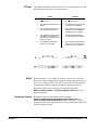
Using with External Pull-ups
The Digital I/O module data lines can be used in an open collector
configuration. Connections for open collector require the use of external
power supplies and pull-up resistors. The internal pull-up mode of the
Digital I/O module should be disabled for open collector output. Figure 2-10
shows a single data line connection. The value of the pull-up resistor is
calculated as follows:
Vcc = 5.0 Vdc
Imax = Iout Low × safety_factor = 48mA × 0.52 = 25mA
Vcc
5
R = ------------ = ------------- = 200Ω
Imax
0.025
The value of TTL high with the 200 Ω pull-up resistor is calculated as
follows:
6200
V High = Vcc × --------------------------- = 4.84Vdc
6200 + 200
Figure 2-10. Typical Open Collector Data Line
28
Configuring the Agilent E1330B Digital I/O
Chapter 2
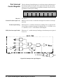
Typical Connection
Figure 2-11 shows a typical driver/receiver connection for data transfer.
The FLG, PIR, and STS lines have a discrete resistive pull-up network. The
data lines do not have a discrete resistive pull-up, but can use an internal
pull-up in the 75ALS160. The internal pull-up requires that the data lines
sink 3.2 mA to pull the line to less than 0.4 V. The I/O, CTL, and RES lines
are open collector, and require external pull-up to logic high.
Figure 2-11. Typical Driver/Receiver Connections
Chapter 2
Configuring the Agilent E1330B Digital I/O Module
29
Notes:
30
Configuring the Agilent E1330B Digital I/O
Chapter 2
Chapter 3
Using the Agilent E1330B Digital I/O
Module
Using This Chapter
This chapter is divided into eight sections about transferring data to and from
the Digital I/O Module and a peripheral:
• Addressing the Module . . . . . . . . . . . . . . . . . . . . . . . . . . . . .
• Operation Overview . . . . . . . . . . . . . . . . . . . . . . . . . . . . . . .
• Default and Reset States . . . . . . . . . . . . . . . . . . . . . . . . . . . .
• Setting the Polarity . . . . . . . . . . . . . . . . . . . . . . . . . . . . . . . .
• Setting the Handshake Mode . . . . . . . . . . . . . . . . . . . . . . . .
• Inputting Data Bytes and Bits . . . . . . . . . . . . . . . . . . . . . . . .
• Outputting Data Bytes and Bits . . . . . . . . . . . . . . . . . . . . . .
• Multiple Port Operations. . . . . . . . . . . . . . . . . . . . . . . . . . . .
• Using Trace Memory . . . . . . . . . . . . . . . . . . . . . . . . . . . . . .
Page 31
Page 32
Page 33
Page 33
Page 34
Page 35
Page 36
Page 37
Page 38
Addressing the Module
The examples shown in this chapter use the default addresses for the
interface, Command module, and Digital I/O module. The address uses both
GPIB primary and secondary addresses. The default address is:
7
09
GPIB Primary Address
Interface Select Code
Command module
GPIB Address
18
GPIB Secondary
Address
Digital I/O module
LADDR
address --------------------
8
To establish these defaults as an I/O path in BASIC, the program examples
use this code:
10 ASSIGN @Dio TO 70918
Each Digital I/O module in a system must have a different logical address.
Additionally, no two instruments in the same system can have the same
logical address. Setting the logical address is described in Chapter 2 —
“Configuring the Agilent E1330B Digital I/O Module”.
Chapter 3
Using the Agilent E1330B Digital I/O Module
31
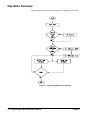
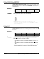
Operation Overview
The following steps illustrate general operation of the Digital I/O module.
Figure 3-1. Agilent E1330B General Operation
32
Using the Agilent E1330B Digital I/O Module
Chapter 3
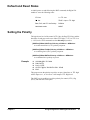
Default and Reset States
At initial power-on and following the *RST command, the Digital I/O
module is set to the following states:
CTL line:
0 = TTL Low
I/O line:
TRUE = input = TTL High
Data, FLG, and CTL line Polarity:
POSitive
Handshake mode:
NONE
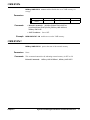
Setting the Polarity
The logical true level of the control (CTL) line, the flag (FLG) line, and the
data lines of each port can be set to either TTL high (> 2.5V) or TTL Low
(< 1.4V) levels. SCPI commands use the POLarity keyword as:
[SOURce:]DIGital:CONTrol n:POLarity <POSitive or NEGative>
to set the control line’s (CTL) polarity on port n.
[SOURce:]DIGital:FLAGn:POLarity <POSitive or NEGative>
to set the flag line’s (FLG) polarity on port n.
[SOURce:]DIGital:DATA n:POLarity <POSitive or NEGative>
to set the data line’s polarity on port n.
Example
10
20
30
40
50
ASSIGN @Dio TO 70918
DIM Pol$ [3]
Pol$ = "POS"
OUTPUT @Dio; "DIG:DATA1:POL "&Pol$
END
This program sets the polarity to positive on port 1 data lines. A TTL high
will be input as a 1, or a bit set to 1 will output a TTL High level.
The *RST (reset) condition is positive polarity for control (CTL), flag
(FLG), and data lines on all ports.
Chapter 3
Using the Agilent E1330B Digital I/O Module
33
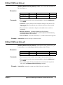
Setting the Handshake Mode
Handshaking ensures correct transfer of data between devices. You must set
both the mode and the timing to establish correct handshaking. Most
handshake modes use the FLG and CTL lines to control the data transfer.
SCPI commands support the following modes of handshaking:
-- LEADing Edge
-- TRAiling Edge
-- PULSe
-- PARTial
-- STRobe
-- NONE
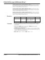
These SCPI commands set the type of handshake mode used:
[SOURce:]DIGital:DATA n[:type]:HANDshake[:MODE] <mode>
[SOURce:]DIGital:HANDshaken[:MODE] <mode>
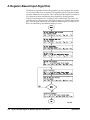
Handshake Timing
Some handshake modes require that a timing value be set.Primarily, the
timing applies to only output functions (the exception is STRobe Input
handshaking mode). These SCPI commands set the timing of the handshake
(where timing applies):
[SOURce:]DIGital:DATA n[:type]:HANDshake:DELay <time>
[SOURce:]DIGital:HANDshakenDELay <time>
Example
10
20
30
40
50
60
70
ASSIGN @Dio TO 70918
DIM Hand$ [4]
Hand$ = "LEAD"
Delay = 0.015
OUTPUT @Dio;"DIG:DATA0:BYTE:HAND "&Hand$
OUTPUT@Dio;"DIG:DATA0:BYTE:HAND:DEL ";Delay
END
Sets the 8-bit port 0 handshake mode to the LEADing Edge handshake mode
and sets the output timing handshake delay to 0.015 seconds.
Detailed descriptions of the handshake modes, timing diagrams, and the use
of the FLG and CTL lines are given in Chapter 4 —“Understanding the
Agilent E1330B Digital I/O Module”.
34
Using the Agilent E1330B Digital I/O Module
Chapter 3
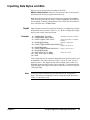
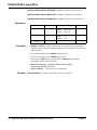
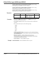
Inputting Data Bytes and Bits
Data input is performed using commands in the SCPI
MEASure:DIGital:DATA n subsystem. The returned value of an input will
depend upon the POLarity programmed for the port.
Both Input and Output operations will attempt to complete the handshake
mode set for the port and may "hang" if required handshake operations are
not completed. To unhang a hung transfer, issue a IEEE 488 selected device
clear. In BASIC this is CLEAR 70918.
Input
Example
Input operations can involve single bits, 8-bit bytes, or multiple bytes. Single
bit operations always return a value of 1 or 0. Byte or multiple byte inputs
always return values in decimal format.
10
20
30
ASSIGN @Dio TO 70918
INTEGER Bits, Bytes, Ready
OUTPUT @Dio;"*RST;*OPC?"
!Establish I/O path to module.
!Reset the module to establish
defaults.
40 ENTER @Dio;Ready
!Wait for completion.
50 OUTPUT @Dio;"MEAS:DIG:DATA0:BIT7?"
!Input a bit on port 0.
60 ENTER @Dio;Bits
70 OUTPUT @Dio;"MEAS:DIG:DATA1?" !Input a byte on port 1.
80 ENTER @Dio;Bytes
90 DISP "Port 0, Bit 7 is "&Bits
!Show the results.
100 DISP "Port 1 byte is "&Bytes
110 END
This example first sets the module to the default state (positive polarity and
no handshake). The state of data line 7 (Bit 7) of port 0 is read. A byte is
input from port 1. The displayed state of the bit input will be either 0 or 1,
depending upon the electrical state of port 0 data line 7. The displayed value
of the byte input will range from 0 (all port 1 data lines low) to 255 (all port
1 data lines high).
Note
Chapter 3
Following a *RST command, the port data lines will be configured as
inputs, with the ports terminating resistors pulling them high. Bits will be
read as a 1 and a byte as 255.
Using the Agilent E1330B Digital I/O Module
35
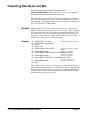
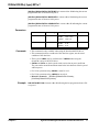
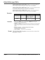
Outputting Data Bytes and Bits
Data output is performed using the commands in SCPI
[SOURce:]DIGital:DATAn subsystem. The TTL levels of an output will
depend upon the POLarity programmed for the port.
Both Input and Output operations will attempt to complete the handshake
mode set for the port and may "hang" if required handshake operations are
not completed. To unhang a hung transfer, issue a IEEE 488selected device
clear. In BASIC this is CLEAR 70918.
Output
Example
Output operations can involve single bits, 8-bit bytes, or multiple bytes.
Single bit output operations always expect a value of 0 or 1. Byte or multiple
byte output operations can accept numbers in decimal, hexadecimal, octal,
or binary formats. The choice of output format is indicated by a special
character (#) in the value to be output. If the # character is not used, the
output value is assumed to be in decimal format.
10
20
30
40
50
ASSIGN @Dio TO 70918
INTEGER Bits, Bytes, Ready
Bits= 1
Bytes = 255
OUTPUT @Dio;"*RST;*OPC?"
!Establish I/O path to module.
!Reset the module to establish
defaults.
60 ENTER @Dio;Ready
!Wait for completion.
70 OUTPUT@Dio;"DIG:DATA0:BIT5 "&VAL$(Bits)&";*OPC?"
!Set port 0 bit 5 true.
80 ENTER @Dio;Ready
!Wait for completion.
90 OUTPUT@Dio;"DIG:DATA1 "&VAL$(Bytes)&";*OPC?"
!Output a byte on port 1.
100 ENTER @Dio;Ready
!Wait for completion.
110 END
This example sets bit 5 on port 0 to a logical true value (with the default
polarity established, the data line is set to TTL high). The example then sets
all the data lines on port 1 to TTL high. Port 0, bit 5 and port 1 data lines will
remain in the TTL high condition until another output command or input
command at the same port is received.
36
Using the Agilent E1330B Digital I/O Module
Chapter 3
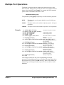
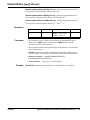
Multiple Port Operations
The Digital I/O module supports multiple port operations using a single
SCPI command. Multiple port operations are shown in the SCPI command
syntax as the optional keyword [:type]. For example, this SCPI command
syntax initiates a handshake and returns a value:
MEAS:DIG:DATAn[:type]?
The optional keyword [:type] is replaced by one of the following keywords:
Example
:BYTE
This keyword, or no keyword (default), is used for 8-bit port
operations.
:WORD
This keyword is used to combine 2 adjacent ports for 16-bit port
operations.
:LWORd
This keyword is used to combine all 4 ports for 32-bit operations.
10
20
30
40
50
60
70
80
90
100
110
120
130
140
150
160
ASSIGN @Dio TO 70918
DIM Pat_1$[8], Pat_2$[8], Hand$[4]
Pat_1$="AAAAAAAA"
Pat_2$ = "55555555"
Hand$ = "LEAD"
OUTPUT @Dio;"*RST;*OPC?"
!Establish I/O path to module.
!Alternating 1 and 0.
!Alternating 0 and 1.
!Reset the module to establish
defaults.
ENTER @Dio;Ready
!Wait for completion.
OUTPUT@Dio;"DIG:DATA0:LWORD:HAND "&Hand$&";*OPC?"
!Set LEADing handshake for 32
bit operations.
ENTER @Dio;Ready
!Wait for completion.
OUTPUT@Dio;"DIG:DATA0:LWORD:HAND:DEL .015;*OPC?"
!Set handshake delay time.
ENTER @Dio;Ready
!Wait for completion.
OUTPUT@Dio;"DIG:DATA0:LWORD #H"&Pat_1$&";*OPC?"
!Set 32 bits, use handshake,
alternating 1 and 0.
ENTER @Dio;Ready
!Wait for completion.
OUTPUT@Dio;"DIG:DATA0:LWORD #H"&Pat_2$&";*OPC?"
!Set 32 bits, use handshake,
alternating 0 and 1.
ENTER @Dio;Ready
!Wait for completion.
END
This example combines all four ports for handshaking and output
operations. The handshake mode is set to LEADing. The output data is given
in hexadecimal as specified by the #H characters. When using multiple port
handshaking, use the highest numbered port CTL line to ensure a correct
handshake.
Chapter 3
Using the Agilent E1330B Digital I/O Module
37
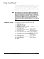
Using Trace Memory
Trace memory can speed input and output operations and free your system
controller during multiple byte input or output operations. A portion of
system memory is set aside and data is read or written as blocks. Trace
memory allows the fastest operation of the Digital I/O module. The rate of
transfer of each block of data is determined by the handshake speed of the
Digital I/O module and the peripheral.
Note
Trace Memory Example 1
Byte swapping may occur when using the :TRACe commands. If you are
using a Motorola processor, the bytes are written or read to memory with
the lowest port receiving the least significant byte (the case when directly
addressing the port through SCPI commands). An Intel processor, however,
when used with the :TRACe commands will swap the order the of the
bytes. The bytes are written or read from memory with the lowest port
receiving the most significant byte and the highest port the least significant
byte.
This example writes 20 bytes as 10 WORDS at ports 0 and 1.
10
20
30
40
50
60
70
80
90
100
110
120
130
140
150
38
RE-SAVE "Trace_1"
ASSIGN @ Dio TO 70918
INTEGER A(1:10) ,Ready
DATA 65,66,67,68,69,70,71,72,73,74 !A, B, C, D, E, F, G, H, I, J.
READ A(*)
OUTPUT @Dio;"*RST;*OPC?"
ENTER @Dio;Ready
!Wait for completion.
OUTPUT@Dio;"SOUR:DIG:TRAC:DEF alpha,100;*OPC?"
!Define memory name alpha.
ENTER @Dio;Ready
!Wait for completion.
OUTPUT @Dio USING"K,10(W)";"SOUR:DIG:TRAC alpha,#220";A(*)
!Fill memory alpha with 20
bytes.
OUTPUT@Dio;"SOUR:DIG:DATA0:WORD:TRAC alpha;*OPC?"
!Output the 20 bytes.
ENTER @Dio;Ready
!Wait for completion.
OUTPUT @Dio;"SOUR:DIG:TRAC:DEL alpha;*OPC?"
!Delete memory alpha.
ENTER @Dio;Ready
!Wait for completion.
END
Using the Agilent E1330B Digital I/O Module
Chapter 3
Trace Memory Example 2
This example writes 20 bytes as 10 WORDS at ports 0 and 1 as in the first
example, it uses an external VME memory board.
10
20
30
40
50
60
70
80
90
100
110
120
130
140
150
160
170
180
Trace Memory Example 3
This example reads 40 WORDS from ports 0 and 1.
10
20
30
40
50
60
70
80
90
100
110
120
130
140
150
Chapter 3
RE-SAVE "Trace_2"
ASSIGN @ Dio TO 70918
INTEGER A(1:10) ,Ready
DATA 65,66,67,68,69,70,71,72,73,74 !A, B, C, D, E, F, G, H, I, J.
READ A(*)
OUTPUT @Dio;"*RST;*OPC?"
ENTER @Dio;Ready
!Wait for completion.
OUTPUT @Dio;"MEM:VME:ADDR #H200000"
!Define memory location.
OUTPUT @Dio;"MEM:VME:SIZE 100"!Reserve 100 bytes.
OUTPUT @Dio;"MEM:VME:STAT ON"!Enable memory.
OUTPUT@Dio;"SOUR:DIG:TRAC:DEF alpha,100;*OPC?"
!Define memory name alpha.
ENTER @Dio;Ready
!Wait for completion.
OUTPUT @Dio USING"K,10(W)";"SOUR:DIG:TRAC alpha,#220";A(*)
!Fill memory alpha with 20
bytes.
OUTPUT@Dio;"SOUR:DIG:DATA0:WORD:TRAC alpha;*OPC?"
!Output the 20 bytes.
ENTER @Dio;Ready
!Wait for completion.
OUTPUT@DIO;"SOUR:DIG:TRAC:DEL alpha,*OPC?"
!Delete memory alpha.
ENTER @Dio;Ready
!Wait for completion.
END
RE-SAVE "Trace_3"
ASSIGN @ Dio TO 70918
DIM Head$[4]
INTEGER A(1:20) ,Ready
OUTPUT @Dio;"*RST;*OPC?"
ENTER @Dio;Ready
!Wait for completion.
OUTPUT@Dio;"SOUR:DIG:TRAC:DEF alpha,80;*OPC?"
!Define memory name alpha.
ENTER @Dio;Ready
!Wait for completion.
OUTPUT@Dio;"MEAS:DIG:DATA0:WORD:TRAC alpha;*OPC?"
!Output 80 bytes.
ENTER @Dio;Ready
!Wait for completion.
OUTPUT @Dio;"SOUR:DIG:TRAC:DATA? alpha"
!Request the data.
ENTER @Dio USING "4A,40(W)";Head$;A(*)
OUTPUT @Dio;"SOUR:DIG:TRAC:DEL alpha;*OPC?"
!Remove memory block.
ENTER@Dio;Ready
!Wait for completion.
END
Using the Agilent E1330B Digital I/O Module
39
Notes:
40
Using the Agilent E1330B Digital I/O Module
Chapter 3
Chapter 4
Understanding the Agilent E1330B Digital
I/O Module
Using This Chapter
This chapter provides explanations of the signal lines, handshake modes,
and port combining for the Digital I/O Module. This chapter has the
following topics.
• Port Description . . . . . . . . . . . . . . . . . . . . . . . . . . . . . . . . . .
• Default and Reset States . . . . . . . . . . . . . . . . . . . . . . . . . . . .
• Setting the Polarity . . . . . . . . . . . . . . . . . . . . . . . . . . . . . . . .
• Using the Handshake Modes. . . . . . . . . . . . . . . . . . . . . . . . .
• Inputting Data Bytes and Bits . . . . . . . . . . . . . . . . . . . . . . . .
• Outputting Data Bytes and Bits . . . . . . . . . . . . . . . . . . . . . .
• Multiple Port Operations. . . . . . . . . . . . . . . . . . . . . . . . . . . .
Page 41
Page 43
Page 43
Page 44
Page 50
Page 51
Page 53
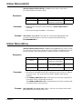
Port Description
Each of the Digital I/O module ports has 8 data lines and 6 control lines. Not
all these lines are required for every application. A simplified diagram of a
port is shown in Figure 1-1. The following subsections describe the use of
these lines.
Data Lines
Each port has 8 data lines, numbered from 0 to 7. The data lines can be set
as an 8-bit group, as part of a larger group, or individually using SCPI
commands.
The logical TRUE condition of the data lines can be controlled with SCPI
commands. Positive polarity is the default. The following table shows the
effect of changing the polarity with Input and Output operations for each
data line.
POSitive Polarity
NEGative Polarity
Chapter 4
Input Operations
Output Operations
TTL High = 1
1 = TTL High
TTL Low = 0
0 = TTL Low
TTL High = 0
0 = TTL High
TTL Low = 1
1 = TTL Low
Understanding the Agilent E1330B Digital I/O Module
41
The FLG Line (Input)
The CTL Line
(Output)
The I/O Line (Output)
Each port has a flag (FLG) line. A flag line is an input line from a peripheral
and has two states: READY and BUSY. A flag line is normally used in
conjunction with the corresponding control line (CTL) to establish a
handshake between a peripheral and the Digital I/O Module. SCPI
commands that define handshake modes typically use the FLG and CTL
lines. The state of the FLG line can also be read with a SCPI command to
implement custom handshakes. Positive polarity is the default. The
following shows the effect of changing the polarity of the FLG line.
POSitive Polarity
TTL High = BUSY = 1
TTL Low = READY = 0
NEGative Polarity
TTL High = READY = 0
TTL Low = BUSY = 1
Each port has a control line (CTL). A control line is an open collector output
line from the Digital I/O module to the peripheral and has two states: TRUE
and FALSE. A control line is normally used in conjunction with the
corresponding flag line on the same port to establish a handshake between a
peripheral and the Digital I/O Module. SCPI commands that define
handshake modes typically use the FLG and CTL lines. The state of the CTL
line can be read and set with SCPI commands to implement custom
handshakes. Positive polarity is the default. The following shows the effect
of changing the polarity of the CTL line.
POSitive Polarity
TTL High = TRUE = ON = 1
TTL Low = FALSE = OFF = 0
NEGative Polarity
TTL High = FALSE = OFF = 0
TTL Low = TRUE = ON = 1
Each port has an open collector I/O line which is output from the Digital I/O
module to the peripheral and has two states: TRUE or FALSE. The state of
the I/O line is not directly programmable.
When the I/O line is:
TTL High = TRUE = 1 = Input
The data transceiver of that port is enabled for input. The peripheral may
respond to the signal by enabling itself to send data.
When the I/O line is:
TTL Low = FALSE = 0 = Output
The data transceiver of that port is enabled for output. The peripheral should
respond to the signal by enabling itself to receive data.
Caution
42
To prevent damage to the Digital I/O module, when the I/O line is
set for Output (TTL Low), the peripheral MUST NOT attempt to
source on any data lines.
Understanding the Agilent E1330B Digital I/O Module
Chapter 4
The STS Line
Each port has a status line labeled STS. The STS line is an input line to the
Digital I/O module. The use of the STS line is only at the register level, and
is not supported by SCPI commands. Refer to Appendix B for more
information about this line.
The PIR Line
Each port has a peripheral interrupt request line labeled PIR. The PIR line is
an input line to the Digital I/O module. The use of the PIR line is only at the
register level, and is not supported by SCPI commands. Refer to Appendix
B for more information about this line.
The RES Line
Each port has a reset line labeled RES. The RES line is an open collector
output line to the peripheral. Control of the RES line is only at the register
level and is not supported by SCPI commands. Refer to Appendix B for
more information about this line.
Default and Reset States
At initial power-on and following the *RST command, the Digital I/O
module is set to the following states:
CTL line:
0 = TTL Low
I/O line:
TRUE = input = TTL High
Data, FLG, and CTL line Polarity:
POSitive
Handshake mode:
NONE
Setting the Polarity
The logical true level of the control (CTL) line, the flag (FLG) line, and the
data lines of each port can be set to either TTL high (>2.5V) or TTL Low
(< 1.4V) levels. SCPI commands use the POLarity keyword as:
[SOURce:]DIGital:CONTrol n:POLarity <POSitive or NEGative>
to set the control line's (CTL) polarity on port n.
[SOURce:]DIGital:FLAGn:POLarity <POSitive or NEGative>
to set the flag line's (FLG) polarity on port n.
[SOURce:]DIGital:DATA n:POLarity <POSitive or NEGative>
to set the data lines polarity on port n.
Example
DIG:DATA1:POL POS
Sets the polarity to positive on port 1 data lines, a TTL high will be input as
a 1, or a bit set to 1 will output a TTL High level.
The *RST (reset) condition is positive polarity for control (CTL),
flag (FLG), and data lines on all ports.
Chapter 4
Understanding the Agilent E1330B Digital I/O Module
43
Using the Handshake Modes
Handshaking ensures correct transfer of data between devices. You must set
both the mode and the timing to establish correct handshaking. SCPI
commands support the following modes of handshaking:
--
LEADing Edge
--
TRAiling Edge
--
PULSe
--
PARTial
--
STRobe
--
NONE
These SCPI commands set the type of handshake mode used:
[SOURce:]DIGital:DATA n[:type]:HANDshake[:MODE] <mode>
[SOURce:]DIGital:HANDshaken[:MODE] <mode>
These SCPI commands set the timing of the handshake (where timing
applies):
[SOURce:]DIGital:DATA n[:type]:HANDshake:DELay <time>
[SOURce:]DIGital:HANDshaken:DELay <time>
44
Understanding the Agilent E1330B Digital I/O Module
Chapter 4
Handshake Modes
The operation of each handshake mode for input or output operations is
described in the following subsections. In these discussions, only the FLG,
CTL, and DATA lines are included. Other port control lines, controlled only
through register access, are described in Appendix B of this manual.
LEADing Edge
The LEADing Edge handshake makes use of both the CTL and FLG lines.
The input and output operations are described below.
INPUT
Chapter 4
OUTPUT
1
The Digital I/O module senses the
FLG line and waits for READY.
1
The Digital I/O module checks the
state of the FLG line (must be
READY).
2
The Digital I/O module sets the
I/O line HIGH.
2
The Digital I/O module sets the
I/O line LOW.
3
The Digital I/O module sets CTL
TRUE.
3
The Digital I/O module places the
data on the data lines.
4
The peripheral senses the CTL
line and places data on the data
lines.
4
After waiting the programmed
delay time, Td, the Digital I/O
module sets CTL to TRUE.
5
The peripheral sets the FLG line
to BUSY indicating data is valid.
5
The peripheral senses the CTL
line and sets the FLG line to
BUSY while it latches the data.
6
The Digital I/O module senses the
FLG line and latches the data.
6
When the Digital I/O module
senses the FLG line in the BUSY
state, it sets the CTL line to
FALSE and monitors the FLG line.
7
The Digital I/O module returns
CTL to FALSE.
7
When the peripheral returns the
FLG line to READY (indicating it
has latched the data) the next
handshake can begin.
8
The peripheral senses the CTL
line and returns the FLG line to
READY.
Understanding the Agilent E1330B Digital I/O Module
45
TRAiling Edge
The TRAiling Edge handshake makes use of both the CTL and FLG lines.
The input and output operations are described below.
INPUT
46
OUTPUT
1
The Digital I/O module senses the
FLG line and waits for READY.
1
The Digital I/O module checks the
state of the FLG line (must be
READY).
2
The Digital I/O module sets the
I/O line HIGH.
2
The Digital I/O module sets the
I/O line LOW.
3
The Digital I/O module sets CTL
TRUE.
3
The Digital I/O module places the
data on the data lines.
4
The peripheral senses the CTL
line and sets the FLG line to
BUSY.
4
After waiting the programmed
delay time, Td, the Digital I/O
module sets CTL to TRUE.
5
The Digital I/O module senses the
FLG BUSY and sets the CTL line
FALSE.
5
The peripheral senses the CTL
line and sets the FLG line to
BUSY while it latches the data.
6
The peripheral senses the CTL
line change and places data on
the data lines.
6
The peripheral returns the FLG
line to READY indicating the end
of data transfer.
7
The peripheral indicates the data
is valid by returning the FLG line
to READY.
7
The Digital I/O module senses the
FLG line in the READY state and
returns CTL to FALSE.
8
The Digital I/O module senses the
FLG READY and latches the data.
Understanding the Agilent E1330B Digital I/O Module
Chapter 4
PULSe
The PULSe handshake makes use of both the CTL and FLG lines. The input
and output operations are described below.
INPUT
Chapter 4
OUTPUT
1
The Digital I/O module senses the
FLG line and waits for READY.
1
The Digital I/O module checks the
state of the FLG line (must be
READY).
2
The Digital I/O module sets the
I/O line HIGH.
2
The Digital I/O module sets the
I/O line LOW.
3
The Digital I/O module sets CTL
TRUE.
3
The Digital I/O module places the
data on the data lines.
4
The peripheral senses the CTL
line and sets the FLG line to
BUSY.
4
After waiting the programmed
delay time, Td, the Digital I/O
module sets CTL to TRUE.
5
The peripheral places the data on
the data lines and indicates valid
data by setting the FLG line to
READY.
5
The Digital I/O module then waits
another delay time, Td, and sets
the CTL line to FALSE.
6
The Digital I/O module senses the
FLG READY, returns CTL to
FALSE, and latches the input
data.
6
The peripheral senses the CTL
line change, sets the FLG line to
BUSY and latches the data.
7
When the data is entered, the
peripheral returns the FLG line to
READY.
Understanding the Agilent E1330B Digital I/O Module
47
PARTial
The PARTial handshake makes use of both the CTL and FLG lines. The
input and output operations are described below.
INPUT
1
The Digital I/O module sets the
I/O line HIGH.
1
The Digital I/O module sets the
I/O line LOW.
2
The Digital I/O module sets CTL
TRUE.
2
The Digital I/O module places the
data on the data lines.
3
The peripheral senses the CTL
line and sets the data lines.
3
After waiting the programmed
delay time, Td, the Digital I/O
module sets CTL to TRUE.
4
The peripheral holds the FLG
line READY for at least
250 nsecs and then sets the FLG
line BUSY to indicate the data is
valid.
4
The peripheral senses the CTL
line change, sets the FLG line to
READY for a minimum of
250 nsecs, latches the data, and
sets the FLG line to BUSY.
5
The Digital I/O module senses
the FLG line change to BUSY
and latches the data.
5
The Digital I/O module senses
the change of the FLG line and
sets CTL to FALSE.
6
48
OUTPUT
The Digital I/O module then sets
the CTL line FALSE.
Understanding the Agilent E1330B Digital I/O Module
Chapter 4
STRobe
The STRobe handshake makes use the CTL line, but not the FLG line. The
input and output operations are described below.
INPUT
NONE
OUTPUT
1
The Digital I/O module sets the
I/O line HIGH.
1
The Digital I/O module sets
the I/O line LOW.
2
The Digital I/O module sets CTL
TRUE.
2
The Digital I/O module places
the data on the data lines.
3
The peripheral senses the CTL
line and sets the data lines.
3
After waiting the programmed
delay time, Td, the Digital I/O
module sets CTL to TRUE.
4
The Digital I/O module waits the
programmed time delay, Td,
after setting CTL TRUE and then
latches the data.
4
The peripheral senses the
CTL line and latches the data.
5
The Digital I/O module then
returns CTL to FALSE.
5
After waiting the programmed
delay time, Td, the Digital I/O
module sets CTL to FALSE.
When handshake is set to NONE, no control or flag lines are used. The
Digital I/O module will input data or output data when programmed. The I/O
line is set for output (LOW) before data is output. Data lines programmed
for output will remain as output until another command is received.
Handshake NONE can be combined with the SCPI commands
MEASure:DIGital:FLAGn and [SOURce:]DIGital:CONTroln to create
custom handshakes.
Handshake Timing
Chapter 4
Handshake timing is set through the SCPI commands
[SOURce:]DIGital:DATAn[:type]:HANDshake:DELay <time> or
[SOURce:]DIGital:HANDshakenDELay <time>. Handshake timing is
generally used for data output operations. Timing for data input affects only
STRobe handshake modes.
Understanding the Agilent E1330B Digital I/O Module
49
Inputting Data Bytes and Bits
Data input is performed using commands in the SCPI
MEASure:DIGital:DATA n subsystem. The returned value of an input will
depend upon the POLarity programmed for the port.
Input operations can involve single bits, 8-bit bytes, or multiple bytes. Single
bit input operations always return a decimal value of 0 or 1. Byte or multiple
byte input operations always return numbers in decimal format.
Both Input and Output operations will attempt to complete the handshake
mode set for the port and may "hang" if required handshake operations are
not completed. To unhang a hung transfer issue a IEEE 488 selected device
clear. In BASIC this is CLEAR 70918.
Bit Input
The SCPI command for inputting the state of a single bit on a data port is:
MEASure:DIGital:DATA n[:type]:BIT m
This command instructs the Digital I/O module to return a value of either 0
or 1, indicating the condition of bit m on port n, following completion of the
input handshake. The value returned depends upon the programmed state of
the port POLarity. In the default state (POSitive polarity) a TTL high on the
data line specified by m will return a 1. For example, the following BASIC
program code will request and display the state of data line 3 (bit-3) on port
4.
120
130
140
OUTPUT @Dio;"MEAS:DIG:DATA4:BIT3?"
ENTER @Dio;Bits
DISP "State of bit 3 on port 4" &Bits
Bit numbers range from 0 to 7 for single port operations. For multiple port
operations, bit numbers can range from 0 to 31. The section “Multiple Port
Operations” beginning on page 53 describes bit numbering for multiple port
operations. For a single port, the data line numbers and bit numbers
correspond:
Dn-7
Dn-6
Dn-5
Dn-4
Dn-3
Dn-2
Dn-1
Dn-0
Bit 7
Bit 6
Bit 5
Bit 4
Bit 3
Bit 2
Bit 1
Bit 0
In this manual the physical data lines are indicated as Dn-1. The n should be
replaced with the port number for the input operation. For example, bit 3 of
port 2 affects the state of data line D2-3.
Byte Input
The SCPI command requesting an 8-bit byte from a data port is:
MEASure:DIGital:DATA n[:BYTE][:VALue]?
This command instructs the Digital I/O module to return a decimal value
between 0 and 255, indicating the condition of the data lines on port n,
following completion of the input handshake. The value returned depends
upon the programmed state of the port POLarity. In the default state
50
Understanding the Agilent E1330B Digital I/O Module
Chapter 4
(POSitive polarity) if all data lines are at a TTL low level, the returned value
will be 0; if all lines are at a TTL high level, the returned value will be 255.
For example, the following BASIC program code will request and display
the decimal value of the data lines on port 2.
120
130
140
OUTPUT @Dio;"MEAS:DIG:DATA2?"
ENTER @Dio;Result
DISP "Decimal value of port 2 data lines ";Result
Port numbers range from 0 to 3 for single port operations. The section
“Multiple Port Operations” beginning on page 53 describes port numbering
for multiple port operations. For a single port, the returned decimal value
will have the following correspondence to the port data lines:
Dn-7
Dn-6
Dn-5
Dn-4
Dn-3
Dn-2
Dn-1
Dn-0
Bit 7
Bit 6
Bit 5
Bit 4
Bit 3
Bit 2
Bit 1
Bit 0
MSB
LSB
Outputting Data Bytes and Bits
Data output is performed using the commands in SCPI
[SOURce:]DIGital:DATAn subsystem. The TTL levels of an output will
depend upon the POLarity programmed for the port.
Output operations can involve single bits, 8-bit bytes, or multiple bytes.
Single bit output operations always expect a value of 0 or 1. Byte or
multiple byte output operations can accept numbers in decimal,
hexadecimal, octal, or binary formats.
Both Input and Output operations will attempt to complete the handshake
mode set for the port and may "hang" if required handshake operations are
not completed. To unhang a hung transfer issue a IEEE 488 selected device
clear. In BASIC this is CLEAR 70918.
Bit Output
The SCPI command for setting the state of a single bit on a data port is:
[SOURce:]DIGital:DATA n[:type]:BITm <value>
This command instructs the Digital I/O module to set bit m on port n to
<value>, using the output handshake. The actual TTL level set on the
corresponding data line depends upon the programmed state of the port
polarity. If <value> is 1 and the default polarity (POSitive polarity) is used,
the data line corresponding to bit m will be set to a TTL high level. For
example, the following BASIC program code will set the state of data line 2
(bit-2) on port 3 to a value of 1.
120 OUTPUT @Dio;"DIG:DATA3:BIT2 1"
Bit numbers range from 0 to 7 for single port operations. For multiple port
operations, bit numbers can range from 0 to 31. The section “Multiple Port
Operations” beginning on page 53 describes bit numbering for multiple port
Chapter 4
Understanding the Agilent E1330B Digital I/O Module
51
operations. For a single port, the data lines number and bit numbers are:
Dn-7
Dn-6
Dn-5
Dn-4
Dn-3
Dn-2
Dn-1
Dn-0
Bit 7
Bit 6
Bit 5
Bit 4
Bit 3
Bit 2
Bit 1
Bit 0
In this manual the physical data lines are indicated as Dn-1. The n should be
replaced with the port number for the input operation. For example, bit 3 of
port 2 affects the state of data line D2-3.
Byte Output
The SCPI command syntax to send an 8-bit byte to a data port is:
[SOURce:]DIGital:DATA n[:BYTE][:VALue] [<base>]<value>
This command instructs the Digital I/O module to set the port n data lines to
<value> using the output handshake. The optional parameter <base> defines
the numbering system to use to implement <value> on the data lines. There
are four values allowed for <base>:
no parameter
decimal format
#H
hexadecimal format
#Q
octal format
#B
binary format
The TTL levels set on the data lines depends upon the programmed port
polarity. In the default state (POSitive polarity) a TTL high level will be set
for any bit set to 1. For example, the following four BASIC program lines
all perform the same function and set the same data lines on port 3:
120
120
120
120
OUTPUT @Dio;"DIG:DATA3
OUTPUT @Dio;"DIG:DATA3
OUTPUT @Dio;"DIG:DATA3
OUTPUT @Dio;"DIG:DATA3
170"
#HAA"
#Q252"
#B10101010"
If port 3 is in the default POSitive polarity mode, the TTL levels set on the
data lines by any of the program lines above will be:
TTL level
High
Low
High
Low
High
Low
High
Low
Data line
D3-7
D3-6
D3-5
D3-4
D3-3
D3-2
D3-1
D3-0
Port numbers range from 0 to 3 for single port operations. The section
“Multiple Port Operations” beginning on page 53 describes port numbering
and byte order for multiple port operations. For single port operations, the
most significant bit is bit 7. The table below shows the bit numbers and data
lines.
Dn-7
Dn-6
Dn-5
Dn-4
Dn-3
Dn-2
Dn-1
Dn-0
Bit 7
Bit 6
Bit 5
Bit 4
Bit 3
Bit 2
Bit 1
Bit 0
MSB
52
Understanding the Agilent E1330B Digital I/O Module
LSB
Chapter 4
Multiple Port Operations
The Digital I/O module supports multiple port operations. You can combine
operations using 2 or 4 ports with a single SCPI command. Multiple port
operations are shown in the SCPI command syntax as the optional keyword
[:type] . For example, this SCPI command syntax initiates a handshake and
returns a value:
MEAS:DIG:DATA n[:type]?
The optional keyword [:type] is replaced by one of the following keywords:
:BYTE
This keyword, or no keyword (default), is used for 8-bit port
operations.
:WORD
This keyword is used to combine 2 adjacent ports for 16-bit port
operations.
:LWORd
This keyword is used to combine all 4 ports for 32-bit operations.
The SCPI keyword :DATAn specifies the port to be used for operations by
replacing n with the port number. Multiple port operations have fixed values
allowed for n. For all operations, if n is omitted, port 0 is assumed. The
values allowed for n are:
Operation
Values of
:BYTE
0, 1, 2, or 3
:WORD
0 or 2
:LWORd
0
n
For example, the following BASIC program code will obtain a decimal
value of the state of the 32 data lines contained in physical ports 0, 1, 2 and 3.
120
130
140
Multiple Port
Handshaking
OUTPUT @Dio;"MEAS:DIG:DATA0:LWORD?"
ENTER @Dio;Result
DISP "32 bit longword at port 4 ";Result
The SCPI command syntax to establish a multiple port handshake and set
handshake timing is:
[SOURce:]DIGital:DATA n[:type]:HANDshake[:MODE] <mode>
[SOURce:]DIGital:DATA n[:type]:HANDshake:DELay <time>
The optional keyword [:type], parameter DATAn, handshake <mode>, and
handshake delay <time>, are all described earlier in this chapter. See the
sections “Handshake Modes”, “Handshake Timing”, and the introduction to
“Multiple Port Operations” for explanations of these keywords and
parameters.
Chapter 4
Understanding the Agilent E1330B Digital I/O Module
53
Multiple port handshaking has the following two abnormalities regarding
the CTL and FLG control lines:
• Input or Output handshaking using the CTL line.
The CTL line is
set TRUE or FALSE sequentially on all ports involved in the
operation, from the lowest numbered port to the highest numbered
port. A slight time delay exists between each port setting the CTL line
TRUE or FALSE. When using handshaking on multiple port
operations, use the highest numbered port CTL line to ensure correct
data transfer.
• Input or Output handshaking using the FLG line.
A change in the
state of any FLG line on any combined port continues the handshake
operation for all the combined ports. FLG lines can also be electrically
combined through a jumper setting (see Chapter 2).
Multiple Port
Input/Output
Data input is performed using commands in the SCPI
MEASure:DIGital:DATA n subsystem. Data output is performed using the
commands in SCPI [SOURce:]DIGital:DATAn subsystem.
The returned value of an input, or the TTL levels of an output, will depend
upon the POLarity programmed.
Both Input and Output operations will attempt to complete the handshake
mode set and may "hang" if required handshake operations are not
completed.
The sections “Byte Input” and “Byte Output”, earlier in this chapter,
describe operations that also apply to multiple port commands. The values
used for input and output operations depend upon the [:type] used in the
command. Values for multiple port output operations are given below.
Input Operations
Format
Range
Output Operations
Format
Range
BYTE
Decimal
0 to 255
Decimal
#H
#Q
#B
-128 to 255
00 to FF
000 to 377
8-bits
WORD
Decimal
-32768
to
32767
Decimal
#H
#Q
#B
-32768 to 32767
0000 to FFFF
00000 to 177777
16-bits
LWORd
Decimal
-2147483648
to
2147483647
Decimal
#H
#Q
#B
-2147483648 to 2147483647
00000000 to FFFFFFFF
0 to 37777777777
32-bits
Table 4-1 shows allowable port combinations for each value of [:type].
You can combine multiple port operations on the same Digital I/O module.
For example, you could define two independent 16-bit ports at port 0 and
port 2.
54
Understanding the Agilent E1330B Digital I/O Module
Chapter 4
Table 4-1. Port Combinations for [:type] Values
8-bit (BYTE) operations
Port #
0
1
2
3
7–0
7–0
7–0
7–0
Data Lines
D0_7–D0_0
D1_7–D1_0
D2_7–D_0
D3_7–D3_0
Parameters
<value>
<value>
<value>
<value>
Bit Designations
16-bit (WORD) operations
Port #
Bit Designations
Data Lines
0
2
15–8
7–0
15–8
7–0
D0_7–D0_0
D1_7–D1_0
D2_7–D_0
D3_7–D3_0
<value>
Parameters
<value>
32-bit (LWORd) operations
Port #
Bit Designations
Data Lines
Parameters
Chapter 4
0
31–24
23–16
15–8
7–0
D0_7–D0_0
D1_7–D1_0
D2_7–D_0
D3_7–D3_0
<value>
Understanding the Agilent E1330B Digital I/O Module
55
Notes:
56
Understanding the Agilent E1330B Digital I/O Module
Chapter 4
Chapter 5
Agilent E1330B Digital I/O Module
Command Reference
Using This Chapter
This chapter describes Standard Commands for Programmable Instrumentation
(SCPI) and summarizes IEEE 488.2 Common (*) Commands applicable to the
Digital I/O Module.
• Command Types. . . . . . . . . . . . . . . . . . . . . . . . . . . . . . . . . . . . . . . . .
• SCPI Command Reference . . . . . . . . . . . . . . . . . . . . . . . . . . . . . . . .
• IEEE 488.2 Common Commands . . . . . . . . . . . . . . . . . . . . . . . . . . .
• Command Quick Reference . . . . . . . . . . . . . . . . . . . . . . . . . . . . . . . .
Page 57
Page 60
Page 98
Page 99
Command Types
Commands are separated into two types: IEEE 488.2 Common Commands and SCPI
Commands.
Common
Command
Format
The IEEE 488.2 standard defines the Common Commands that perform functions
like reset, self-test, status byte query, etc. Common Commands are four or five
characters in length, always begin with the asterisk character (*), and may include
one or more parameters. The command keyword is separated from the first
parameter by a space character. Some examples of Common Commands are shown
below:
*RST
SCPI
Command
Format
*ESR 32
*STB?
SCPI commands perform functions like closing switches, making measurements,
querying instrument states, or retrieving data. A subsystem command structure is a
hierarchical structure that usually consists of a top level (or root) command, one or
more lower level commands, and their parameters. The following example shows
part of a typical subsystem:
[SOURce:]
DIGital
:DATAn
[:VALue]?
:BITm?
[SOURce:] is the root command, DIGital is a second level command, :DATAn is a
third level command (where n is the port number 0–3), and [:VALue] and :BITm are
fourth level commands (where m is the queried bit location).
Chapter 5
Agilent E1330B Digital I/O Module Command Reference
57
Command
Separator
A colon (:) always separates one command from the next lower level command. This
is illustrated as follows:
MEASure:DIGital:DATAn:VALue?
Colons separate the root command from the second level (MEASure:DIGital) and the
second from third level (DIGital:DATAn), and so forth.
Abbreviated
Commands
The command syntax shows most commands as a mixture of upper and lower case
letters. The upper case letters indicate the abbreviated spelling for the command. For
shorter program lines, send the abbreviated form. For better program readability, you
may send the entire command. The instrument will accept either the abbreviated
form or the entire command.
For example, if the command syntax shows MEASure, then MEAS and MEASURE
are both acceptable forms. Other forms of MEASure, such as MEASU or MEASUR
will generate an error. You may use upper or lower case letters. Therefore,
MEASURE, measure, and MeAsUrE are all acceptable.
Command keywords can be entered in their full form, as shown above, or can be
entered in their short form. In this manual, the entry required in short form
commands is always capitalized. The short form is generally used for examples in
this manual.
Implied
Commands
Implied commands are those which appear in square brackets ([ ]) in the command
syntax. (Note that the brackets are not part of the command and are not sent to the
instrument.) Suppose you send a second level command but do not send the
preceding implied command. In this case, the instrument assumes you intend to use
the implied command and it responds as if you had sent it. Examine this excerpt from
the [SOURce:] subsystem shown below:
[SOURce:]
DIGital
:DATAn
[:VALue] <parameter>
:BITm <parameter>
Both the root command [SOURce:], and forth level command [:VALue], are implied
commands. To set the instrument to output a logical 1 to bit 0 of port 3, you may send
either:
SOURce:DIGital:DATA3:BIT0 1
Note
58
or
DIGital:DATA3:BIT0 1
You must include a space between the keywords and any parameters.
Agilent E1330B Digital I/O Module Command Reference
Chapter 5
Parameters
Parameter Types. The following table contains explanations and examples of
parameter types you might see later in this chapter.
Parameter
Type
Explanations and Examples
Numeric
Accepts all commonly used decimal representations of numbers
including optional signs, decimal points, and scientific notation.
123, 123E2, -123, -1.23E2, .123, 1.23E-2, 1.23000E-01. Special
cases include MIN, MAX, and DEF. MIN selects minimum value
available, MAX selects maximum value available, and DEF
selects default or reset value.
Boolean
Represents a single binary condition that is either true or false.
1 or ON; 0 or OFF.
Discrete
Selects from a finite number of values. These parameters use
mnemonics to represent each valid setting.
An example is the DIGital:CONTroln:POLarity <polarity>
command where polarity can be either POS or NEG.
Optional Parameters. Parameters shown within square brackets ([]) are optional
parameters. (Note that the brackets are not part of the command and are not sent to
the instrument.) If you do not specify a value for an optional parameter, the
instrument chooses a default value. For example, consider the
DISPlay:MONitor:PORT? [<MIN| MAX| DEF>] command. If you send the command
without specifying a parameter, the command returns the state of the port last
addressed. If you send the MIN parameter or the DEF parameter, the command
returns 0. If you send the MAX parameter, the command returns 3. Be sure to place
a space between the command and the parameter.
Keyword
Substitutions
Some commands indicate a keyword substitution by showing the keyword bold type
with an all lower case keyword. For example, in the SCPI command
MEASure:DIGital:DATA n[:type] the keyword [:type] should be replaced by one
these parameters:
:BYTE
:WORD
:LWORd
Linking
Commands
Linking IEEE 488.2 Common Commands with SCPI Commands.
Use a semicolon between the commands. For example:
*RST;DIG:CONT2 1 or DIG:CONT2:POL POS;*OPC?
Linking Multiple SCPI Commands.
Use both a semicolon and a colon between the commands. For example:
DIG:DATA2:POL NEG;:DIG:DATA2:BIT3 1
Chapter 5
Agilent E1330B Digital I/O Module Command Reference
59
SCPI Command Reference
This section describes the Standard Commands for Programmable Instruments
(SCPI) commands for the Digital I/O Module. Commands are listed alphabetically
by subsystem and within each subsystem.
60
Agilent E1330B Digital I/O Module Command Reference
Chapter 5
DISPlay Subsystem
The DISPlay subsystem turns on the Monitor mode. Monitor mode enables the
Agilent E1301 Mainframe display, or an external terminal connected to either a
B-size or a C-size mainframe. Parameters related to the state of the data and control
lines are shown. Refer to the appropriate Command Module User's Guide (Agilent
E1405/E1406) for supported terminal types. The parameters displayed are:
Syntax
--
port number
--
polarity
--
handshake mode
--
state of the control line
--
state of the flag line
--
values on the data lines in both decimal and hexadecimal
DISPlay
:MONitor
:PORT <port >[AUTO| MIN| MAX| DEF]
:PORT? [<MAX|MIN|DEF>]
[:STATe] <mode>
[:STATe]?
:MONitor:PORT
DISPlay:MONitor:PORT <port>[AUTO |MIN |MAX|DEF] sets the displayed port
number.
Parameters
Comments
Parameter Name
Parameter Type
Range of Values
Default
<port >
Numeric
or
Discrete
none, 0 through 3
AUTO
MIN, MAX, AUTO, DEF
• In the AUTO mode of operation, the display shows the state of the port last
programmed. MIN sets port 0. MAX sets port 3. No parameter or DEF sets the
AUTO mode of operation.
• Related Commands: DISPlay:MONitor[:STATe], DISPlay:MONitor:PORT?
• *RST Condition: DISPlay:MONitor:PORT AUTO
Example
Chapter 5
DISP:MON:PORT 3 sets the port to be monitored to 3.
Agilent E1330B Digital I/O Module Command Reference
61
:MONitor:PORT?
DISPlay:MONitor:PORT? [<MAX|MIN|DEF>], with no parameter, returns a
decimal number indicating the port being monitored. If AUTO was selected as the
port parameter in the DISP:MON:PORT AUTO command, the query returns a -1.
If DEF is specified, the query always returns -1. If MAX is specified, the query
returns the maximum port (always 3). If MIN is specified, the query returns the
minimum port (always 0).
Parameters
Parameter Type
Range of Values
Default
MAX|MIN|DEF
Optional
or
Discrete
None
None
MAX, MIN, or DEF
• Related Commands: DISPlay:MONitor:PORT, DISPlay:MONitor[:STATe]
• *RST Condition: Not applicable.
Comments
Example
Parameter Name
DISP:MON:PORT? identifies the port being monitored.
:MONitor[:STATe]
DISPlay:MONitor[:STATe] <mode> turns the monitor mode ON or OFF.
Parameters
Comments
Parameter Name
Parameter Type
Range of Values
Default
<mode>
Boolean
0|1|ON|OFF
0|OFF
• DISPlay:MONitor
ON or DISPlay:MONitor 1 enables the terminal display of
port parameters. The parameters are updated to the terminal following each
new command accessing a port. DISPlay:MONitor OFF or
DISPlay:MONitor 0 turns the monitor mode OFF.
• A keyboard entry at the terminal will set DISP:MON OFF.
• This command does not perform an actual readback of the port data lines.
It returns the last programmed state of the data lines.
• Related Commands: DISPlay:MONitor:PORT, DISPlay:MONitor:PORT?
• *RST Condition: DISPlay:MONitor[:STATe] OFF|0
Example
62
DISP:MON ON displays the state of the last port programmed.
Agilent E1330B Digital I/O Module Command Reference
Chapter 5
:MONitor[:STATe]?
DISPlay:MONitor[:STATe]? returns a number indicating whether the monitor mode
is enabled or disabled: 1 = ON, 0 = OFF.
Parameters
Chapter 5
None.
Agilent E1330B Digital I/O Module Command Reference
63
MEASure Subsystem
The MEASure subsystem defines the command set for the Digital I/O Module input
statements.
Syntax
MEASure
:DIGital
:DATAn
[:BYTE]
:BITm?
:TRACe <name>
[:VALue]?
:LWORd
:BITm?
:TRACe <name>
[:VALue]?
:WORD
:BITm?
:TRACe <name>
[:VALue]?
:FLAGn?
:DIGital:DATAn[:type]:BITm?
MEASure:DIGital:DATA n:BYTE:BITm? reads the state on bit m of 8-bit port n
after the completion of the handshake.
MEASure:DIGital:DATA n:WORD:BITm? reads the state on bit m of 16-bit port n
after the completion of the handshake.
MEASure:DIGital:DATA n:LWORd:BITm? reads the state on bit m of the 32-bit
port n after the completion of the handshake.
Parameters
Comments
Parameter Name
Parameter Type
Range of Values
Default
DATAn
Numeric
BYTE
WORD
LWORd
none, 0, 1, 2, or 3
none, 0 or 2
none or 0
0
BITm
Numeric
BYTE
WORD
LWORd
0–7
0–15
0–31
0
• Input data is always assumed to be in binary format, since only a single bit of
data is being read. The command returns either a 0 or 1.
• The keyword :LW32 may be used instead of :LWORd when using the
downloaded version of the SCPI driver.
• :DATAn is the keyword used for commands relating to the data at port n. The
port number n must be the last character of the keyword without spaces.
64
Agilent E1330B Digital I/O Module Command Reference
Chapter 5
• If n is omitted, bit 0 is used.
• :BITm is the keyword that specifies the bit read by this command. Like the
:DATA n keyword, no space can be between the keyword :BIT and the bit
number m parameter.
• Related Commands: [SOURce:]DIGital:DATAn:POLarity
• *RST Condition: Set to input on all ports.
Example
MEAS:DIG:DATA2:BIT4? reads port 2, bit 4 (data line D2–4).
:DIGital:DATAn[:type]:TRACe
MEASure:DIGital:DATA n[:BYTE]:TRACe <name> reads 8-bit port n after the
completion of the handshake and stores the data block in <name>.
MEASure:DIGital:DATA n:WORD:TRACe <name> reads 16-bit port n after the
completion of the handshake and stores the data block in <name>.
MEASure:DIGital:DATA n:LWORd:TRACe <name> reads the 32-bit port n after
the completion of the handshake and stores the data block in <name>.
Parameters
Comments
Parameter Name
Parameter Type
DATAn
Numeric
<name>
String
Range of Values
BYTE
WORD
LWORd
Default
0
none, 0, 1, 2, or 3
none, 0 or 2
none or 0
previously defined block
name (max 12 characters)
None
• :TRACe
<name> is the keyword (maximum 12 characters) that specifies the
block where the data should be stored. This block must have been previously
defined by the [SOURce:]DIGital:TRACe:DEFine command.
• This command will completely fill the named block. The defined block size
sets the amount of data read. The block size must by an integer multiple of the
[:type] keyword used in this command. For example,valid block sizes for
:LWORd are 4, 8, 12, 16, etc.
• Input data is returned in decimal format. Other formats are not supported for
input, however, data output may be in binary, octal, decimal or hexadecimal.
• The keyword :LW32 may be used instead of :LWORd when using the
download version of the SCPI driver.
• :DATAn
is the keyword used for commands relating to the data at port n. The
port number n must be the last character of the keyword without spaces.
• Related Commands:
MEASure:DIGital:DATAn[:VALue]?,
[SOURce:]DIGital:TRACe:DEFine
• *RST Condition:
Example
Set to input on all ports.
MEAS:DIG:DATA0:WORD:TRACe first_block reads 16-bit data from port 0 and
stores it in the predefined user memory location first_block.
Chapter 5
Agilent E1330B Digital I/O Module Command Reference
65
:DIGital:DATAn[:type][:VALue]?
MEASure:DIGital:DATA n[:BYTE][:VALue]? reads one byte from 8-bit port n after
the completion of the handshake and returns a decimal number between 0 and 255.
MEASure:DIGital:DATA n:WORD[:VALue]? reads 2 bytes (one word) from 16-bit
port n after the completion of the handshake and returns a decimal number between
-32768 and 32767.
MEASure:DIGital:DATA n:LWORd[:VALue]? reads 4 bytes (one long word) from
the 32-bit port n after the completion of the handshake and returns a decimal number
between -2 31 and (231-1).
Parameters
Comments
Parameter Name
Parameter Type
DATAn
Numeric
Range of Values
BYTE
WORD
LWORd
Default
0
none, 0, 1, 2, or 3
none, 0 or 2
none or 0
• Input data from the Digital I/O is returned in decimal format. Other formats are
not supported for input, however, data output to the Digital I/O may be in
binary, octal, decimal, or hexadecimal.
• The keyword :LW32 may be used instead of :LWORd when using the
downloaded version of the SCPI driver.
• Chapter 4 - “Understanding the Agilent E1330B Digital I/O Module” describes
the byte order of multiple byte reads.
• :DATAn is the keyword used for commands relating to the data at port n.
The port number n must be the last character of the keyword without spaces.
• If n is omitted, port 0 is used.
• Related Commands: [SOURce:]DIGital:DATAn[:type][:VALue],
MEASure:DIGital:DATAn[:type]:BITm?
• *RST Condition:
Examples
Set to input positive true on all ports.
MEAS:DIG:DATA1? reads 8-bit port 1 data. If all data lines are set to 1, this
command returns the value 255.
MEAS:DIG:DATA0:LWORd? reads 32-bit port 0 data. If all data lines are set to 1,
this command returns the value -1.
66
Agilent E1330B Digital I/O Module Command Reference
Chapter 5
:DIGital:FLAGn?
MEASure:DIGital:FLAGn? reads the status of the flag line on port n and returns a
0 or 1 to show whether a peripheral has set the flag line to READY or BUSY.
Parameters
Comments
Parameter Name
Parameter
Type
Range of Values
Default
FLAGn
Numeric
none, 0, 1, 2, or 3
0
• MEASure:DIGital:FLAGn?
is used to implement custom handshakes.
The handshake mode must be set to NONE to use these commands.
• :FLAGn
is the keyword used for commands relating to the flag line at port n.
The port number n must be the last character of the keyword without spaces.
• If n is omitted, FLAG0 is used.
• MEASure:DIGital:FLAGn? may be affected by the condition of the flag
combining jumpers. Refer to Chapter 2 for additional information.
• Related Commands:
[SOURce:]DIGital:CONTroln:POLarity?,
[SOURce:]DIGital:CONTroln[:VALue], [SOURce:]DIGital:FLAGn:POLarity,
[SOURce:]DIGital:FLAG n:POLarity?
Example
Chapter 5
MEAS:DIG:FLAG1? reads the port 1 flag line.
Agilent E1330B Digital I/O Module Command Reference
67
MEMory Subsystem
The MEMory subsystem defines the command set for enabling the use of external
VME memory for storing traces and macros. The addressable range is #H200000
through #HDFFFF8 in A24 space.
Syntax
MEMory
:DELete
:MACRo <name>
:VME
:ADDRess [<base>]<address>
:ADDRess? [MIN |MAX]
:SIZE [<base>]<size>
:SIZE? [MIN |MAX]
:STATe <state>
:STATe?
:DELete:MACRo
MEMory:DELete:MACRo <name> deletes a single macro previously recorded
using the *DMC common command.
Parameters
Comments
Parameter Name
Parameter Type
Range of Values
Default
<name>
String
Previously defined block name
(maximum 12 characters)
None
• name
must have been previously defined by a *DMC (Define Macro) common
command.
• The maximum length for name is 12 characters.
• This command purges a single, specific macro; the *PMC common command
purges all macros.
Example
68
MEM:DEL:MACR test_macro deletes macro named test_macro previously defined
using the *DMC common command.
Agilent E1330B Digital I/O Module Command Reference
Chapter 5
:VME:ADDRess
MEMory:VME:ADDRess [<base>]<address> establishes the address of add-on
VME memory in the system which can then be used to store block data in commands
with the :TRACe keyword.
Parameters
Comments
Parameter Name
Parameter Type
Range of Values
Default
<base>
Discrete
none, #H, #Q, or #B
Decimal
<address>
Numeric
or
Discrete
20000016–DFFFF8 16
None
MIN or MAX
• base specifies the numeric format as decimal, hexadecimal, octal, or binary.
IEEE-488.2 specifies the following values for this parameter:
Decimal = no parameter
Hexadecimal = #H
Octal = #Q
Binary = #B
• Valid values for base and address are #H200000 (2,097,152 decimal) through
#HDFFFF8 (14,680,056 decimal).
• For this memory to actually be used it must also have a defined length and
have been turned ON using the MEMory:VME:STATe command.
• Related Commands:
[SOURce:]DIGital:TRACe:DEFine,
MEMory:VME:ADDress?, MEMory:VME:SIZE, MEMory:VME:STATe
• *RST Condition:
Example
#H200000
MEM:VME:ADDR #H200000 sets the starting VME address to 20000016.
:VME:ADDRess?
MEMory:VME:ADDRess? [<MIN|MAX>] queries for the current VME memory
address. The optional parameter lets you query for the fixed minimum or maximum
address.
Parameters
Comments
Parameter Name
Parameter Type
Range of Values
Default
MIN|MAX
Discrete
none, MIN, or MAX
None
• This command always returns the address in decimal format.
• The address returned using MIN is always 2,097,152.
• The address returned using MAX is always 14,680,056.
• Related Commands: MEMory:VME:ADDRess, MEMory:VME:SIZE?,
MEMory:VME:STATe?
Chapter 5
Agilent E1330B Digital I/O Module Command Reference
69
:VME:SIZE
MEMory:VME:SIZE [<base>]<size> sets the size, in bytes, of the external memory.
Parameters
Comments
Parameter Name
Parameter Type
Range of Values
Default
<base>
Discrete
none, #H, #Q, or #B
Decimal
<size>
Numeric
or
Discrete
00000016 - C00000 16
or
MIN or MAX
None
None
• Address plus size must not exceed #HE00000.
• base specifies the numeric format as decimal, hexadecimal, octal, or binary.
IEEE-488.2 specifies the following values for this parameter:
Decimal = no parameter
Hexadecimal = #H
Octal = #Q
Binary = #B
• Related Commands:
MEMory:VME:ADDRess?, MEMory:VME:SIZE?,
MEMory:VME:STATe?
• *RST Condition:
#H000000.
:VME:SIZE?
MEMory:VME:SIZE? [<MIN |MAX>] queries for the current VME memory size.
The optional parameter lets you query for the fixed maximum or minimum VME
memory size.
Parameters
Comments
Parameter Name
Parameter Type
Range of Values
Default
MIN|MAX
Discrete
none, MIN, or MAX
None
• This command always returns the memory size in decimal format.
• The size returned using MIN is always 0.
• The size returned using MAX is always 12582912.
• Related Commands: MEMory:VME:ADDRess?, MEMory:VME:SIZE,
MEMory:VME:STATe?
70
Agilent E1330B Digital I/O Module Command Reference
Chapter 5
:VME:STATe
MEMory:VME:STATe <state> enables/disables the use of VME memory for
storage.
Parameters
Comments
Parameter Name
Parameter Type
Range of Values
Default Value
<state>
Boolean
0|1|ON|OFF
0|OFF
• Related Commands:
[SOURce:]DIGital:TRACe:DEFine,
[SOURce:]DIGital:TRACe[:DATA], MEMory:VME:ADDress,
MEMory:VME:SIZE
• *RST Condition:
Example
Set to OFF.
MEM:VME:STAT ON enables access to the VME memory.
:VME:STATe?
MEMory:VME:STATe? queries the state of the external memory.
Parameters
Comments
None.
This command returns 0 or 1, indicating external memory is OFF or ON.
Related Commands:
Chapter 5
MEMory:VME:ADDRess?, MEMory:VME:SIZE?
Agilent E1330B Digital I/O Module Command Reference
71
[SOURce:] Subsystem
The [SOURce:] subsystem defines the command set for the Digital I/O module
output statements. It also defines the state and polarity of the control line (CTL), the
polarity of the flag line (FLG), the handshaking mode, and handshake delay for both
data input and output. The root command, [SOURce:], is optional.
[SOURce:]
DIGital
:CONTroln
:POLarity <POS| NEG>
:POLarity?
[:VALue] <0 |1 or ON| OFF>
[:VALue]?
:DATAn
[:BYTE]
:BITm <0| 1>
:BITm?
:HANDshake
:DELay <time>
:DELay?
[:MODE] <NONE |LEADing |TRAiling
|PULSe| PARTial|STRobe>
[:MODE]?
:POLarity <POS| NEG>
:POLarity?
:TRACe <name>
[:VALue] [<base>]<value>
[:VALue]?
:LWORd
:BITm <0| 1>
:BITm?
:HANDshake
:DELay <time>
:DELay?
[:MODE] <NONE |LEADing |TRAiling
|PULSe| PARTial|STRobe>
[:MODE]?
:POLarity <POS| NEG>
:POLarity?
:TRACe <name>
[:VALue] [<base>]<value>
[:VALue]?
72
Agilent E1330B Digital I/O Module Command Reference
Chapter 5
[SOURce:]
DIGital
:DATAn
:WORD
:BITm <0| 1>
:BITm?
:HANDshake
:DELay <time>
:DELay?
[:MODE] <NONE |LEADing |TRAiling
|PULSe| PARTial|STRobe>
[:MODE]?
:POLarity <POS| NEG>
:POLarity?
:TRACe <name>
[:VALue] [<base>]<value>
[:VALue]?
:FLAGn
:POLarity <POS| NEG>
:POLarity?
:HANDshaken
:DELay <time>
:DELay?
[:MODE] <NONE |LEADing |TRAiling
|PULSe| PARTial|STRobe>
[:MODE]?
:IOn?
:TRACe
:CATalog?
[:DATA] <name>,<block_data>
[:DATA]? <name>
:DEFine <name>,<size>,[<fill>]
:DEFine? <name>
:DELete
:ALL
[:NAME] <name>
Chapter 5
Agilent E1330B Digital I/O Module Command Reference
73
DIGital:CONTroln:POLarity
[SOURce:]DIGital:CONTroln:POLarity <polarity> sets the CTL line voltage level
for logical true in port n to either TTL high for POSitive polarity or TTL low for
NEGative polarity.
Parameters
Comments
Parameter Name
Parameter Type
Range of Values
Default
CONTroln
Numeric
none, 0, 1, 2, or 3
0
<polarity>
Discrete
POSitive or NEGative
None
• Control lines are always accessed by their 8-bit port number.
• :CONTroln is the keyword used for commands relating to the control (CTL)
line at port n. The port number n must be the last character of the keyword
without spaces.
• If n is omitted, port 0 is used.
• The control line is used with the flag line to handshake data to and from
peripherals.
• Related Commands:
[SOURce:]DIGital:CONTroln:POLarity?,
[SOURce:]DIGital:CONTroln[:VALue],
[SOURce:]DIGital:FLAG n:POLarity,
[SOURce:]DIGital:FLAG n:POLarity?
• *RST Condition:
Example
POLarity = POSitive.
DIG:CONT0:POL POS sets logical true to TTL high on port 0 control line.
DIGital:CONTroln:POLarity?
[SOURce:]DIGital:CONTroln:POLarity? returns a three character string, either
POS or NEG, indicating the logical true condition of the control (CTL) line at port n.
Parameters
Comments
Parameter Name
Parameter Type
Range of Values
Default
CONTroln
Numeric
none, 0, 1, 2, or 3
0
• :CONTroln
is the keyword used for commands relating to the control (CTL)
line at port n. The port number n must be the last character of the keyword
without spaces.
• If n is omitted, port 0 is used.
Example
74
DIG:CONT0:POL? queries the state of the logical true condition on port 0.
Agilent E1330B Digital I/O Module Command Reference
Chapter 5
DIGital:CONTroln[:VALue]
[SOURce:]DIGital:CONTroln[:VALue] <value> sets or clears the control line on
the selected port n.
Parameters
Comments
Parameter Name
Parameter Type
Range of Values
Default
CONTroln
Numeric
none, 0, 1, 2, or 3
0
<value>
Boolean
0 or 1, OFF or ON
None
• This command is used to create custom handshakes when the HANDshake is
set to NONE.
• :CONTroln is the keyword used for commands relating to the control (CTL)
line at port n. The port number n must be the last character of the keyword
without spaces.
• The control line is used with the flag line to handshake data to and from
peripherals.
• Related Commands:
[SOURce:]DIGital:CONTroln:POLarity,
[SOURce:]DIGital:CONTroln:POLarity?, [SOURce:]DIGital:FLAGn:POLarity,
[SOURce:]DIGital:FLAG n:POLarity?
• *RST Condition:
Example
Clears the control line; i.e., sets the control line to logical 0.
DIG:CONT2 1 sets the 8-bit port 2 control line true.
DIGital:CONTroln[:VALue]?
[SOURce:]DIGital:CONTroln[:VALue]? reads the state of the control line on port
n and returns a 0 or 1, indicating the logical condition of the CTL line.
Parameters
Comments
Parameter Name
Parameter Type
Range of Values
Default
CONTroln
Numeric
none, 0, 1, 2, or 3
0
• This command is only available when using the downloaded SCPI driver.
• This command is used to create custom handshakes when the HANDshake is
set to NONE.
• The condition of the CTL line returned by this command is the logical true
value set by the DIGital:CONTroln:POLarity command.
Example
Chapter 5
DIG:CONT2? returns the current state of the 8-bit port 2 control line.
Agilent E1330B Digital I/O Module Command Reference
75
DIGital:DATAn[:type]:BITm
[SOURce:]DIGital:DATAn[:BYTE]:BITm <value> sets bit m on 8-bit port n.
[SOURce:]DIGital:DATAn:WORD:BITm <value> sets bit m on 16-bit port n.
[SOURce:]DIGital:DATAn:LWORd:BITm <value> sets bit m on 32-bit port n.
Parameters
Comments
Parameter Name
Parameter Type
Range of Values
DATAn
Numeric
BYTE
WORD
LWORd
none, 0, 1, 2, or 3
none, 0 or 2
none or 0
0
BITm
Numeric
BYTE
WORD
LWORd
0–7
0–15
0–31
0
<value>
Numeric
0 or 1
Default
None
• :DATAn and :BITm are the keywords used to write data to port n and bit m.
The port number n and bit number m must be the last character of the keyword
without spaces.
• For 16-bit operations using :WORD, n must be 0 or 2.
• For 32-bit operations using :LWORd, n must be 0.
• The keyword :LW32 may be used instead of :LWORd when using the
download version of the SCPI driver.
• Related Commands:
[SOURce:]DIGital:DATAn:POLarity,
[SOURce:]DIGital:DATA n[:VALue]
• *RST Condition:
Example
76
All ports are set for data input.
DIG:DATA3:BIT4 1 sets bit 4 (the 5th bit) of port 3 to logical 1.
Agilent E1330B Digital I/O Module Command Reference
Chapter 5
DIGital:DATAn[:type]:BITm?
[SOURce:]DIGital:DATAn[:BYTE]:BITm? returns a 0 or 1 indicating the current
programmed state of bit m on 8-bit port n.
[SOURce:]DIGital:DATAn:WORD:BITm? returns a 0 or 1 indicating the current
programmed state of bit m on 16-bit port n.
[SOURce:]DIGital:DATAn:LWORd:BITm? returns a 0 or 1 indicating the current
programmed state of bit m on 32-bit port n.
Parameters
Comments
Parameter Name
Parameter Type
Range of Values
Default
DATAn
Numeric
BYTE
WORD
LWORd
none, 0, 1, 2, or 3
none, 0 or 2
none or 0
0
BITm
Numeric
BYTE
WORD
LWORd
0–7
0–15
0–31
0
• This command is only available when using the downloaded SCPI driver.
• This command performs a readback of the data line register, not the actual
condition of the data lines.
• The keyword :LW32 may be used instead of :LWORd when using the
download version of the SCPI driver.
• :DATAn and :BITm are the keywords used to write data to port n and bit m.
The port number n and bit number m must be the last character of the keyword
without spaces.
• For 16-bit operations using :WORD, n must be 0 or 2.
• For 32-bit operations using :LWORd, n must be 0.
• Related Commands: [SOURce:]DIGital:DATAn:POLarity,
[SOURce:]DIGital:DATA n[:VALue]
Example
DIG:DATA3:BIT4:VAL? returns a 0 or 1 indicating the last programmed state of bit
4 on port 3.
Chapter 5
Agilent E1330B Digital I/O Module Command Reference
77
DIGital:DATAn[:type]:HANDshake:DELay
[SOURce:]DIGital:DATAn[:BYTE]:HANDshake:DELay <time> sets the delay
between data output and control line for data output at 8-bit port n.
[SOURce:]DIGital:DATAn:WORD:HANDshake:DELay <time> sets the delay
between data output and control line for data output at 16-bit port n.
[SOURce:]DIGital:DATAn:LWORd:HANDshake:DELay <time> sets the delay
between data output and the control line for data output at 32-bit port n.
Parameters
Comments
Parameter Name
Parameter Type
Range of Values
DATAn
Numeric
<time>
Numeric
2 µs to 15 µs
20 µs to 150 µs
200 µs to 1.5 ms
2ms to 15ms
Discrete
MIN|MAX|DEF
BYTE
WORD
LWORd
none, 0, 1, 2, or 3
none, 0 or 2
none or 0
Default
0
None
• This command is related to the handshake mode in use. Chapter 3 describes the
handshake modes and timing.
• This command sets strobe pulse width for input and output STRobe
handshakes.
• The delay time must be set to the same value on all ports used in a multiple
port operation.
• MAX sets a 15ms delay. DEF sets 2 µs delay. MIN sets 0.0 delay and is illegal
for PULse or STRobe handshake modes.
• DIGital:DATAn:HANDshake[:MODE] NONE command ignores any
programmed delay time. For all other modes of handshaking, 2 µs is the
minimum recommended.
• Specific bands of delay settings are NOT allowed. These are:
0 µs > <time> < 2 µs
150 µs > <time> < 200 µs
15 µs > <time> < 20 µs
1.5ms > <time> < 2.0 ms
The controller uses a rounded-up value for <time> if these values are specified.
• The keyword :LW32 may be used instead of :LWORd when using the
download version of the SCPI driver.
• DIGital:DATAn[:type]:HANDshake is the sequence used for commands
relating to data handshaking at ports defined by n. The port number n must be
the last character of the keyword without spaces.
• Related Commands: [SOURce:]DIGital:CONTroln:POLarity,
[SOURce:]DIGital:CONTroln[:VALue], [SOURce:]DIGital:FLAGn:POLarity,
[SOURce:]DIGital:HANDshake n[:MODE]
• *RST Condition: Delay is set to 2 µs.
Example
78
DIG:HAND3:DEL .005 sets the delay between the data output and the assertion of
the control line to true on 8-bit port 3 to 5 ms.
Agilent E1330B Digital I/O Module Command Reference
Chapter 5
DIGital:DATAn[:type]:HANDshake:DELay?
[SOURce:]DIGital:DATAn[:BYTE]:HANDshake:DELay? queries for the delay
time between data output and the control line for data output at 8-bit port n and
returns a decimal number between 0 and .015.
[SOURce:]DIGital:DATAn:WORD:HANDshake:DELay? queries for the delay
time between data output and the control line for data output at 16-bit port n and
returns a decimal number between 0 and .015.
[SOURce:]DIGital:DATAn:LWORd:HANDshake:DELay? queries for the delay
time between data output and the control line for data output at 32-bit port n and
returns a decimal number between 0 and .015.
Parameters
Comments
Parameter Name
Parameter Type
Range of Values
DATAn
Numeric
BYTE
WORD
LWORd
MIN|MAX|DEF
Discrete
None or MIN |MAX|DEF
Default
0
none, 0, 1, 2, or 3
none, 0 or 2
none or 0
None
• The delay time must be set to the same value on all ports used in a multiple
port operation.
• The keyword :LW32 may be used instead of :LWORd when using the
download version of the SCPI driver.
• DIG:DATAn[:type]:HANDshake is the sequence used for commands relating
to data handshaking at ports defined by n. The port number n must be the last
character of the keyword without spaces.
• MIN or DEF returns 0.000002. MAX returns 0.015.
Chapter 5
Agilent E1330B Digital I/O Module Command Reference
79
DIGital:DATAn[:type]:HANDshake[:MODE]
[SOURce:]DIGital:DATAn[:BYTE]:HANDshake[:MODE] <mode> selects the
type of handshake and defines the timing relationship between the control (CTL)
line, the flag (FLG) line, and when data is transferred in either direction between the
Digital I/O Module and a peripheral on the 8-bit port n.
[SOURce:]DIGital:DATAn:WORD:HANDshake[:MODE] <mode> selects the
handshake mode used on the 16-bit port n.
[SOURce:]DIGital:DATAn:LWORd:HANDshake[:MODE] <mode> selects the
handshake mode used on the 32-bit port n.
Parameters
Parameter Name
Parameter Type
Range of Values
DATAn
Numeric
BYTE
WORD
LWORd
<mode>
Discrete
NONE, LEADing, TRAiling,
PULse, PARTial, or STRobe
Default
0
none, 0, 1, 2, or 3
none, 0 or 2
none or 0
NONE
• Handshake modes are described in Chapter 3.
• The handshake mode must be the same on all ports used in a multiple port
operation.
• The keyword :LW32 may be used instead of :LWORd when using the
downloaded version of the SCPI driver.
• DIGital:DATAn[:type]HANDshake is the sequence used for commands
relating to data handshaking at port n. The port number n must be the last
character of the keyword without spaces.
• NONE deletes all automatic data handshaking between the Digital I/O module
and the peripheral. For custom handshaking, the control and the flag lines are
controlled by the [SOURce:]DIGital:CONTroln and MEASure:DIGital:FLAGn
commands.
• Related Commands:
[SOURce:]DIGital:CONTroln:POLarity,
[SOURce:]DIGital:CONTroln[:VALue], [SOURce:]DIGital:FLAGn:POLarity,
[SOURce:]DIGital:HANDshake n:DELay
• *RST Condition:
Example
80
Mode is NONE on all ports.
DIG:DATA3:HAND LEAD sets the handshake mode to LEADing on 8-bit port 3.
Agilent E1330B Digital I/O Module Command Reference
Chapter 5
DIGital:DATAn[:type]:HANDshake[:MODE]?
[SOURce:]DIGital:DATAn[:BYTE]:HANDshake[:MODE]? returns a string
indicating the type of handshake set on the 8-bit port n.
[SOURce:]DIGital:DATAn:WORD:HANDshake[:MODE]? returns a string
indicating the type of handshake set on the 16-bit port n.
[SOURce:]DIGital:DATAn:LWORd:HANDshake[:MODE]? returns a string
indicating the type of handshake set on the 32-bit port n.
Parameters
Comments
Parameter Name
Parameter Type
DATAn
Numeric
Range of Values
BYTE
WORD
LWORd
Default
none, 0, 1, 2, or 3
none, 0 or 2
none or 0
0
• The keyword :LW32 may be used instead of :LWORd when using the
download version of the SCPI driver.
• The handshake mode must be the same on all ports used in a multiple port
operation.
• This command will return one of the following strings:
NONE
LEAD
TRA
PULS
PART
STR
• :DATAn[:type]HANDshake? is the sequence used for commands relating to
data handshaking at port n. The port number n must be the last character of the
keyword without spaces.
• Related Commands:
[SOURce:]DIGital:CONTroln:POLarity,
[SOURce:]DIGital:CONTroln[:VALue], [SOURce:]DIGital:FLAGn:POLarity,
[SOURce:]DIGital:HANDshake n:DELay
• *RST Condition:
Example
Chapter 5
Mode is NONE on all ports.
DIG:DATA3:HAND? returns the handshake mode set on port 3.
Agilent E1330B Digital I/O Module Command Reference
81
DIGital:DATAn[:type]:POLarity
[SOURce:]DIGital:DATAn[:BYTE]:POLarity <polarity> sets the data line voltage
level for logical true in the 8-bit port n to either TTL high for POSitive polarity or
TTL low for NEGative polarity.
[SOURce:]DIGital:DATAn:WORD:POLarity <polarity> sets the data line voltage
level for logical true in the 16-bit port n to either TTL high for POSitive polarity or
TTL low for NEGative polarity.
[SOURce:]DIGital:DATAn:LWORd:POLarity <polarity> sets the data line voltage
level for logical true in the 32-bit port n to either TTL high for POSitive polarity or
TTL low for NEGative polarity.
Parameters
Comments
Parameter Name
Parameter Type
DATAn
Numeric
<polarity>
Discrete
Range of Values
BYTE
WORD
LWORd
none, 0, 1, 2, or 3
none, 0 or 2
none or 0
POSitive or NEGative
Default
0
None
• :DATAn is the keyword used for commands relating to the data lines at port n.
The port number n must be the last character of the keyword without spaces.
• Related Commands:
[SOURce:]DIGital:DATAn:BITm,
[SOURce:]DIGital:DATA n:POLarity?, [SOURce:]DIGital:DATAn[:VALue]
• *RST Condition:
Example
POLarity = POSitive
DIG:DATA0:POL POS sets logical true to TTL high on 8-bit port 0 data lines.
DIGital:DATAn[:type]:POLarity?
[SOURce:]DIGital:DATAn[:BYTE]:POLarity? returns a string, either POS or NEG,
indicating the logical true condition of the data lines of 8-bit port n.
[SOURce:]DIGital:DATAn:WORD:POLarity? returns a string, either POS or NEG,
indicating the logical true condition of the data lines of 16-bit port n.
[SOURce:]DIGital:DATAn:LWORd:POLarity? returns a string, either POS or
NEG, indicating the logical true condition of the data lines of 32-bit port n.
Parameters
Example
Parameter Name
Parameter Type
DATAn
Numeric
Range of Values
BYTE
WORD
LWORd
none, 0, 1, 2, or 3
none, 0 or 2
none or 0
Default
0
DIG:DATA0:POL? returns the state of the logical true condition on port 0 as either
POS or NEG.
82
Agilent E1330B Digital I/O Module Command Reference
Chapter 5
DIGital:DATAn[:type]:TRACe
[SOURce:]DIGital:DATAn[:BYTE]:TRACe <name> writes the named block of
data to 8-bit port n whenever the port is ready to start a new handshake.
[SOURce:]DIGital:DATAn:WORD:TRACe <name> writes the named block of data
to 16-bit port n whenever the port is ready start a new handshake.
[SOURce:]DIGital:DATAn:LWORd:TRACe <name> writes the named block of
data to 32-bit port n whenever the port is ready to start a new handshake.
Parameters
Comments
Parameter Name
Parameter Type
DATAn
Numeric
<name>
String
Range of Values
BYTE
WORD
LWORd
Default
none, 0, 1, 2, or 3
none, 0 or 2
none or 0
Name of user memory block
(maximum 12 characters)
0
None
• The keyword :LW32 may be used instead of :LWORd when using the
download version of the SCPI driver.
• :DATAn and :TRACe are the keywords used to write data to port n from block
name. The port number n must be the last character of the keyword without
spaces.
• Related Commands:
[SOURce:]DIGital:DATAn:POLarity,
[SOURce:]DIGital:DATA n[:VALue]
• *RST Condition:
Example
All ports are set for data input.
DIG:DATA2:TRAC:WORD first_block writes data from the user memory block
first_block to 16-bit port 2.
Chapter 5
Agilent E1330B Digital I/O Module Command Reference
83
DIGital:DATAn[:type][:VALue]
[SOURce:]DIGital:DATAn[:BYTE][:VALue] [<base>]<value> writes data to 8-bit
port n. Values can be binary, octal, decimal, or hexadecimal.
[SOURce:]DIGital:DATAn:WORD[:VALue] [<base>]<value> writes data to 16-bit
port n. Values can be binary, octal, decimal, or hexadecimal.
[SOURce:]DIGital:DATAn:LWORd[:VALue] [<base>]<value> writes data to
32-bit port n. Values can be binary, octal, decimal, or hexadecimal.
Parameters
Comments
Parameter Name
Parameter Type
DATAn
Numeric
<base>
Discrete
<value>
Numeric
Range of Values
BYTE
WORD
LWORd
0
none, 0, 1, 2, or 3
none, 0 or 2
none or 0
None, #H, #Q, or #B
BYTE
WORD
LWORd
Default
-27 to (28-1)
-215
to
Decimal
None
(216-1)
-231 to (231-1)
• The keyword :LW32 may be used instead of :LWORd when using the
download version of the SCPI driver.
• base specifies the numeric format as decimal, hexadecimal, octal, or binary.
IEEE-488.2 specifies the following values for this parameter:
Decimal = no parameter
Hexadecimal = #H
Octal = #Q
Binary = #B
• :DATAn is the keyword used for commands relating to data output at port n.
The port number n must be the last character of the keyword without spaces.
• Related Commands:
[SOURce:]DIGital:DATAn:BITm,
[SOURce:]DIGital:DATA n:POLarity
• *RST Condition:
Examples
All ports are set for data input.
DIG:DATA3 27 writes the binary equivalent of the decimal number 27 (00011011)
to 8-bit port 3.
DIG:DATA3 #B00011011 writes the same byte of data as in the example above to
port 3, but in binary format.
84
Agilent E1330B Digital I/O Module Command Reference
Chapter 5
DIGital:DATAn[:type][:VALue]?
[SOURce:]DIGital:DATAn[:BYTE][:VALue]? returns the programmed state of
8-bit port n as a decimal number between 0 and 255.
[SOURce:]DIGital:DATAn:WORD[:VALue]? returns the programmed state of
16-bit port n as a decimal number between -32768 and 32767.
[SOURce:]DIGital:DATAn:LWORd[:VALue]? returns the programmed state of
32-bit port n as a decimal number between -231 and (231- 1).
Parameters
Comments
Parameter Name
Parameter Type
DATAn
Numeric
Range of Values
BYTE
WORD
LWORd
none, 0, 1, 2, or 3
none, 0 or 2
none or 0
Default
0
• This command is only available when using the downloaded SCPI driver.
• The keyword :LW32 may be used instead of :LWORd when using the
download version of the SCPI driver.
• This command returns the programmed state of the data lines, not the actual
state of the data lines.
• :DATAn is the keyword used for commands relating to data output at port n.
The port number n must be the last character of the keyword without spaces.
• Related Commands:
[SOURce:]DIGital:DATAn:BITm,
[SOURce:]DIGital:DATA n:POLarity
• *RST Condition:
Example
Chapter 5
All ports are set for data input.
DIG:DATA3? returns the decimal equivalent of the data lines on 8-bit port 3.
Agilent E1330B Digital I/O Module Command Reference
85
DIGital:FLAGn:POLarity
[SOURce:]DIGital:FLAGn:POLarity <polarity> sets the voltage level for logical
true to either TTL high, POSitive, or TTL low, NEGative on the FLG handshake
line.
Parameters
Comments
Parameter Name
Parameter Type
Range of Values
Default
FLAGn
Numeric
none, 0, 1, 2, or 3
0
<polarity>
Discrete
POSitive or NEGative
None
• :FLAGn is the keyword used for commands relating to the flag line at port n.
The port number n must be the last character of the keyword without spaces.
• Related Commands:
[SOURce:]DIGital:CONTroln:POLarity,
[SOURce:]DIGital:CONTroln:POLarity?, [SOURce:]DIGital:FLAGn:POLarity?
• *RST Condition:
Example
POLarity = POSitive
DIG:FLAG0:POL POS sets logical true to TTL high on the port 0 flag line.
DIGital:FLAGn:POLarity?
[SOURce:]DIGital:FLAGn:POLarity? returns a string, either POS or NEG,
indicating the logical true condition of the flag (FLG) line.
Parameters
Example
Parameter Name
Parameter Type
Range of Values
Default
FLAGn
Numeric
none, 0, 1, 2, or 3
0
SOURCE:DIGITAL:FLAG0:POLARITY? uses long commands to query the state of
the logical true condition on port 0.
DIG:FLAG0:POL? performs the same function as the example above with short
commands.
86
Agilent E1330B Digital I/O Module Command Reference
Chapter 5
DIGital:HANDshaken:DELay
[SOURce:]DIGital:HANDshaken:DELay <time> sets the time between data valid
and the assertion of the control line to TRUE for port n. This form of the command
operates on 8-bit ports only.
Parameters
Comments
Parameter Name
Parameter Type
Range of Values
Default
HANDshaken
Numeric
None, 0, 1, 2, or 3
None
<time>
Numeric
2 µs to 15 µs
20 µs to 150 µs
200 µs to 1.5ms
2ms to 15ms
None
Discrete
MIN|MAX|DEF
• :HANDshaken is the keyword used for commands relating to data
handshaking at port n. The port number n must be the last character of the
keyword without spaces.
• This command sets the strobe pulse width for both input and output STRobe
handshakes.
• The delay time must be set to the same value on all ports used in a multiple
port operation.
• MAX sets a 15ms delay. DEF sets 2 µs delay. MIN sets a delay of 0, and is illegal
for PULse and STRobe handshakes.
• DIGital:HANDshaken
NONE command sets the delay to 0. For all other
modes of handshaking, 2 µs is the minimum.
• Specific bands of delay settings are NOT allowed. These are:
0 µs > <time> < 2 µs
150 µs > <time> < 200 µs
15 µs > <time> < 20 µs
1.5ms > <time> < 2.0 ms
The controller uses a rounded-up value for <time> if these values are specified.
• Related Commands:
[SOURce:]DIGital:CONTroln:POLarity,
[SOURce:]DIGital:CONTroln[:VALue], [SOURce:]DIGital:FLAGn:POLarity,
[SOURce:]DIGital:HANDshake n[:MODE]
• *RST Condition:
Example
Chapter 5
Delay is set to 2 µs.
DIG:HAND3:DEL .005 sets the delay between the data output and the assertion of
the control line to true on 8-bit port 3 to 5 ms.
Agilent E1330B Digital I/O Module Command Reference
87
DIGital:HANDshaken:DELay?
[SOURce:]DIGital:HANDshaken:DELay? queries for the time between data valid
and the assertion of the control line to TRUE. This command operates on 8-bit ports
and returns a decimal value between 0 and 0.015.
Parameters
Comments
Parameter Name
Parameter Type
Range of Values
Default
HANDshaken
Numeric
None, 0, 1, 2, or 3
0
MIN|MAX|DEF
Discrete
None or MIN|MAX|DEF
None
• The delay time must be set to the same value on all ports used in a multiple
port operation.
• :HANDshaken is the keyword used for commands relating to data
handshaking at 8-bit port n. The port number n must be the last character of the
keyword without spaces.
• MIN or DEF returns 0.000002. MAX returns 0.015.
Example
DIG:HAND0:DEL? queries the delay time between data valid and the assertion of
the control line to TRUE on 8-bit port 0.
DIGital:HANDshaken[:MODE]
[SOURce:]DIGital:HANDshaken[:MODE] <mode> selects the type of handshake
mode to use to transfer data in either direction between the Digital I/O module and a
peripheral on 8-bit port n. Handshakes are initiated by execution of a DIGital:DATA n
or MEASure:DIGital:DATAn? command. This form of the HANDshake command
operates only on 8-bit ports.
Parameters
Comments
Parameter Name
Parameter Type
Range of Values
Default
HANDshaken
Numeric
None, 0, 1, 2, or 3
0
<mode>
Discrete
NONE, LEADing, TRAiling,
PULSe, PARTial, or STRobe
NONE
• :HANDshaken is the keyword used for commands relating to data
handshaking at port n. The 8-bit port number n must be the last character of the
keyword without spaces.
• NONE deletes all automatic data handshaking between the Digital I/O Module
and peripheral. For custom handshaking, the control and flag lines are
controlled by the DIGital:CONTroln and DIGital:FLAGn commands.
• Related Commands:
[SOURce:]DIGital:HANDshaken:DELay,
[SOURce:]DIGital:CONTroln:POLarity
• *RST Condition:
Example
88
Mode is NONE on all ports.
DIG:HAND3 LEAD sets the handshake mode to LEADing on 8-bit port 3.
Agilent E1330B Digital I/O Module Command Reference
Chapter 5
DIGital:HANDshaken[:MODE]?
[SOURce:]DIGital:HANDshaken[:MODE]? returns a string indicating the current
handshake mode of 8-bit port n. This form of the HANDshake command operates
only on 8-bit ports.
Parameters
Comments
Parameter Name
Parameter Type
Range of Values
Default
HANDshaken
Numeric
None, 0, 1, 2, or 3
0
• This command will return one of the following strings:
NONE
LEAD
TRA
PULS
PART
STR
• :HANDshaken is the keyword used for commands relating to data
handshaking at port n. The port number n must be the last character of the
keyword without spaces.
DIGital:IOn?
[SOURce:]DIGital:IOn? returns a 0 or 1 indicating the current condition of the I/O
line on port n.
Parameters
Comments
Parameter Name
Parameter Type
Range of Values
Default
IO n
Numeric
None, 0, 1, 2, or 3
0
• This command is only available when using the downloaded SCPI driver.
• The I/O line's polarity is fixed and is as follows:
-- When Digital I/O module is programmed to output data, the I/O line is set
low.
-- When Digital I/O module is programmed to input data, the I/O line is set
high.
• :IOn is the keyword used for commands relating to the I/O line at port n. The
port number n must be the last character of the keyword without spaces.
Chapter 5
Agilent E1330B Digital I/O Module Command Reference
89
DIGital:TRACe:CATalog?
[SOURce:]DIGital:TRACe:CATalog? lists the currently available data blocks.
Parameters
Comments
None.
• This command catalogs all blocks in VME memory and all blocks in the
mainframe system memory.
• The command returns a string.
Example
DIG:TRAC:CAT? would return this string if both alpha and beta had been
previously defined; "alpha","beta".
DIGital:TRACe[:DATA]
[SOURce:]DIGital:TRACe[:DATA] <name>,<block_data> writes a block of data
to a previously defined user memory block.
Parameters
Comments
Parameter Name
Parameter Type
Range of Values
Default
<name>
String
Name of user memory
block (maximum 12
characters)
None
<block_data>
Numeric/String
Numeric header and
ASCII block data
None
• <name> must have been previously defined by a DIGital:TRACe:DEFine
command.
• The maximum length for <name> is 12 characters.
• <block_data> is of the form <#digits><length><block> where:
<#digits> tells how many digits are used to define <length>;
<length> tells how many bytes are to be transferred in <block>;
<block> contains the actual data to transfer.
Example
90
DIG:TRAC:DATA first_block,#210ABCDEFGHIJ sends the data “ABCDEFGHIJ”
to the user memory block first_block. Since the ASCII character A has a decimal
value of 65, the equivalent of 65 is stored in the first byte of first_block (and so on).
Agilent E1330B Digital I/O Module Command Reference
Chapter 5
DIGital:TRACe[:DATA]?
[SOURce:]DIGital:TRACe[:DATA]? <name> reads a block of data from a
previously defined user memory block.
Parameters
Comments
Parameter Name
Parameter Type
Range of Values
Default
<name>
String
Name of user memory block
(maximum 12 characters)
None
• name must have been previously defined by a DIGital:TRACe:DEFine
command.
• The maximum length for name is 12 characters.
Example
DIG:TRACe? first_block reads data from a block named first_block. If the
previous command example is sent, this command will return the string
#210ABCDEFGHIJ.
DIGital:TRACe:DEFine
[SOURce:]DIGital:TRACe:DEFine <name>,<size>,[<fill >] defines a block of data
as a user memory block, names the block for future reference, and fills the block with
the last parameter. If the last parameter is absent, the block is filled with zeros.
Parameters
Comments
Parameter Name
Parameter Type
Range of Values
Default
<name>
String
Name of user memory block
(maximum 12 characters)
None
<size>
Numeric
Up to 12 Mbytes (depending
on memory installed)
None
<fill>
Numeric
0–255
0
• The firmware can handle blocks with a total memory space of up to 12 Mbytes
of memory space. The actual amount available depends on the memory
installed.
• If the MEMory:VME:STATe
ON command has been used, this command will
create blocks in the external add-on memory.
If the MEMory:VME:STATe OFF command has been used, this command will
create blocks in the system memory.
Example
Chapter 5
DIG:TRAC:DEF first_block, 256 defines a 256 byte user memory block named
first_block and fills each byte with a zero.
Agilent E1330B Digital I/O Module Command Reference
91
DIGital:TRACe:DEFine?
[SOURce:]DIGital:TRACe:DEFine? <name> returns the size of a previously
defined user memory block in bytes. The command returns a decimal number in the
range of 0 to 12,582,912.
Parameters
Comments
Parameter Name
Parameter Type
Range of Values
Default
<name>
String
Name of user memory block
(maximum 12 characters)
None
• <name> must have been previously defined by a DIGital:TRACe:DEFine
command. The maximum length for <name> is 12 characters.
DIGital:TRACe:DELete:ALL
[SOURce:]DIGital:TRACe:DELete:ALL deletes all previously defined user
memory data blocks.
Parameters
None.
DIGital:TRACe:DELete[:NAME]
[SOURce:]DIGital:TRACe:DELete[:NAME] <name> deletes a previously defined
user memory data block.
Parameters
Comments
Example
92
Parameter Name
Parameter Type
Range of Values
Default
<name>
String
Name of user memory block
(maximum 12 characters)
None
<name> must have been previously defined by a DIGital:TRACe:DEFine command.
The maximum length for <name> is 12 characters.
DIG:TRACe:DEL first_block deletes a user memory block named first_block.
Agilent E1330B Digital I/O Module Command Reference
Chapter 5
STATus Subsystem
The STATus subsystem controls the SCPI-defined Operation and Questionable
Signal Status Registers and the Standard Event Registers. Each is comprised of a
Condition Register, an Event Register, an enable mask, and transition filters.
Each Status Register works as follows: when a condition occurs, the appropriate bit
in the Condition Register is set or cleared. If the corresponding transition filter is
enabled for that bit, the same bit is set in the associated Event Register. The contents
of the Event Register and the enable mask are logically ANDed bit-for-bit; if any bit
of the result is set, the summary bit for that register is set in the status byte. The status
byte summary bit for the Operation Status Register is bit 7; for the Questionable
Signal Status Register, bit 3; and for the Standard Event Register, bit 5.
Syntax
Note
Chapter 5
STATus
:OPERation
:CONDition?
:ENABle
:ENABle?
[:EVENt]?
:PRESet
:QUEStionable
:CONDition?
:ENABle
:ENABle?
[:EVENt]?
This subsystem is provided for compatibility. The Digital I/O module does not use
the Operation Status or Questionable Status Registers.
Agilent E1330B Digital I/O Module Command Reference
93
:OPERation:CONDition?
STATus:OPERation:CONDition? returns the contents of the Operation Status
Condition Register. Reading the register does not affect its contents. This command
does not affect the Agilent E1330 Digital I/O module.
:OPERation:ENABle
STATus:OPERation:ENABle <mask > specifies which bits of the associated Event
Register are included in its summary bit. The summary bit is the bit-for-bit logical
AND of the Event Register and the unmasked bit(s). This command does not affect
the Agilent E1330 Digital I/O module.
Parameters
Parameter Name
Parameter Type
Range of Values
Default
<mask>
Numeric or
non-decimal
numeric
0 through +32767
None
The non-decimal numeric forms are the #H, #Q, or #B formats specified by
IEEE-488.2.
:OPERation:ENABle?
STATus:OPERation:ENABle? returns the mask set for the Operation Status
Register. This command does not affect the Agilent E1330 Digital I/O module.
:OPERation[:EVENt]?
STATus:OPERation[:EVENt]? returns the contents of the Operation Event Status
Register. Reading the register clears all bits in the register. This command does not
affect the Agilent E1330 Digital I/O module.
:PRESet
STATus:PRESet clears both the Operation Status Enable and Questionable Status
Enable Registers. This command does not affect the Agilent E1330 Digital I/O
module.
94
Agilent E1330B Digital I/O Module Command Reference
Chapter 5
:QUEStionable:CONDition?
STATus:QUEStionable:CONDition? returns the contents of the Questionable
Status Condition Register. Reading the register does not affect its contents. This
command does not affect the Agilent E1330 Digital I/O module.
:QUEStionable:ENABle
STATus:QUEStionable:ENABle <mask > specifies which bits of the associated
Event Register are included in its summary bit. The summary bit is the bit-for-bit
logical AND of the Event Register and the unmasked bit(s). This command does not
affect the Agilent E1330 Digital I/O module.
Parameters
Parameter Name
Parameter Type
Range of Values
Default
<mask>
Numeric or
non-decimal
numeric
0 through +32767
None
The non-decimal numeric forms are the #H, #Q, or #B formats specified by
IEEE-488.2.
:QUEStionable:ENABle?
STATus:QUEStionable:ENABle? returns the mask set for the Questionable Status
Register. This command does not affect the Agilent E1330 Digital I/O module.
:QUEStionable[:EVENt]?
STATus:QUEStionable[:EVENt]? returns the contents of the Questionable Status
Event Register. Reading the register clears all bits in the register. This command
does not affect the Agilent E1330 Digital I/O module.
Chapter 5
Agilent E1330B Digital I/O Module Command Reference
95
SYSTem Subsystem
The SYSTem subsystem returns information about the module.
Syntax
SYSTem
:CDEScription? <number>
:CTYPe? <number>
:ERRor?
:VERsion?
:CDEScription?
SYSTem:CDEScription? <number> returns the module description.
Parameters
Comments
Parameter Name
Parameter Type
Range of Values
Default
<number>
Numeric
1
None
• This command is only available when using the downloaded SCPI driver.
• <number> is the instrument number. Because each Digital I/O module is a
single instrument, <number > is always 1.
• The command returns the following string:
Quad 8-bit Digital I/O
:CTYPe?
SYSTem:CTYPe? <number > returns the module number and manufacturer.
Parameters
Comments
Parameter Name
Parameter Type
Range of Values
Default
<number>
Numeric
0 to 99
None
• This command is only available when using the downloaded SCPI driver.
• The command returns the following string (revision number may vary and the
serial number is always set to 0):
HEWLETT-PACKARD,E1330B,0,A.05.00
96
Agilent E1330B Digital I/O Module Command Reference
Chapter 5
:ERRor?
SYSTem:ERRor? queries the Error Register for the error value and returns a string
error message to identify the error type. The errors are held in an error buffer and
read in a First-In-First-Out manner by this command.
Comments
• Returns the error number and error string. If no errors are in the error buffer,
returns: +0,"No error".
• Related Commands: *ERR
• *RST Condition: None.
Example
SYST:ERR? queries the mainframe for errors.
:VERSion?
SYSTem:VERsion? returns the SCPI version to which this instrument complies.
Comments
Returns a decimal value in the form:
YYYY.R
where YYYY is the year, and R is the revision number within that year.
Chapter 5
Agilent E1330B Digital I/O Module Command Reference
97
IEEE 488.2 Common Commands
The following table lists the IEEE 488.2 Common (*) Commands that can be
executed by the Agilent E1330B Digital I/O Module. For more information on
Common Commands, refer to ANSI/IEEE Standard 488.2-1987.
Note
These commands apply to many instruments and are not documented in detail here.
See ANSI/IEEE Standard 488.2-1987 for more information.
*IDN?
Identification query
Returns identification string of the Digital I/O Module.
*RST
Reset
Sets all ports to input mode, handshake NONE, and polarity POS.
*TST?
Self-Test Query
Always returns 0.
*OPC
Operation Complete
Sets the request for OPC flag when all pending operations have been
completed. Also sets the OPC bit in the Standard Event Register.
*OPC?
Operation Complete Query
Returns a 1 to the output queue when all pending operations are complete.
*WAI
Wait to Continue
Halts execution of commands and queries until the "No Operation
Pending" message is true.
*CLS
Clear status
Clears all Event Registers, the Request for OPC flag, and all queues
(except output queue).
*ESE<mask>
Event status enable
Sets the bits in the Event Status Enable Register.
*ESE?
Event status enable query
Queries the Event Status Enable Register.
*ESR?
Event status register query
Queries and clears the contents of the Standard Event Status Register.
*SRE<mask>
Service request enable
Sets the Service Request Enable Register bits, and corresponding Serial
Poll Status Byte Register bits, to generate a service request.
*SRE?
Service request enable query
Queries the contents of the Service Request Enable Register.
*STB?
Read status byte query
Queries the contents of the Status Byte Register.
*TRG
Trigger
*RCL<n>
Recall saved state
Recalls stored module configuration in the memory location set by <n>.
*SAV<n>
Save state
Stores the module configuration in the memory location set by <n>.
*EMC <n>
Enable macro
Enable execution of macro <n>.
*EMC? <n>
Enable macro query
Queries execution state of macro <n>.
*RMC
Remove macros
Removes all macros.
*LMC
List macros
Lists macros by name.
*DMC
Define macro
Defines a macro.
*GMC
Menu query
Get results of menu query.
*PMC
Purge macros
Purges all system macros.
98
Agilent E1330B Digital I/O Module Command Reference
Chapter 5
Command Quick Reference
The following tables summarize SCPI Commands for the Agilent E1330B Digital
I/O module.
Command
DISPlay:
MEASure:
MEMory:
Chapter 5
Description
MONitor:PORT <port> [AUTO |MIN|MAX|DEF]
Sets the displayed monitor port number.
MONitor:PORT? [<MAX|MIN|DEF>]
Returns the monitored port number.
MONitor[:STATe] <mode>
Turns the monitor mode of the display ON or OFF.
MONitor[:STATe]?
Returns the state of the monitor mode.
DIGital:DATAn[:type]:BITm?
Reads the state on bit m on port n after completion of
handshake.
DIGital:DATAn[:type]:TRACe <name>
Reads port n after completion of handshake and stores block.
DIGital:DATAn[:type][:VALue]?
Reads bytes from port n after completion of handshake.
Assumes decimal format of input data.
DIGital:FLAGn?
Reads the port n FLAG line. Returns 0 or 1.
Used to implement custom handshakes.
DELete:MACRo <name>
Deletes a macro.
VME:ADDRess [<base>]<address>
Sets the address for add-on VME system memory.
VME:ADDRess? [<MIN|MAX>]
Returns the current add-on VME memory address.
VME:SIZE [<base>]<size>
Sets the size of the add-on VME memory.
VME:SIZE? [<MIN|MAX>]
Returns the current size of the add-on VME memory.
VME:STATe <state>
Sets the state (ON or OFF) of the assigned VME memory.
When this is OFF, all memory commands refer to the base
system memory.
VME:STATe?
Returns the current state (0 or 1) of the add-on VME memory.
Agilent E1330B Digital I/O Module Command Reference
99
Command
[SOURce:]
100
Description
DIGital:CONTroln:POLarity <POS|NEG>
Sets logical true level of control line on port n.
DIGital:CONTroln:POLarity?
Returns current logical true polarity of port n.
DIGital:CONTroln[:VALue] <0|1 or ON|OFF>
Sets or clears control line on port n. Command used to create
custom handshakes when HANDshake is set to NONE.
DIGital:CONTroln[:VALue]?
Returns the current state of the control line on port n
(downloaded SCPI driver only).
DIGital:DATAn[:type]:BITm <0|1>
Sets bit m on port n.
DIGital:DATAn[:type]:BITm?
Returns the programmed state of bit m on the port n
(downloaded SCPI driver only).
DIGital:DATAn[:type]:HANDshake:DELay <time>
Sets delay between data output and assertion of control line
for data output on port n. Also sets strobe pulse for both
output and input STRobe handshake.
DIGital:DATAn[:type]:HANDshake:DELay?
Returns the time between data valid and assertion of control
line to TRUE.
DIGital:DATAn[:type]:HANDshake[:MODE]
<NONE|LEADing|TRAiling|
PULSe|PARTial|STRobe>
Selects type of handshake to transfer data between port n
and peripheral. Handshakes are initiated by execution of
DIG:DATAn or MEAS:DIG:DATAn? commands.
DIGital:DATAn[:type]:HANDshake[:MODE]?
Returns the current handshake mode set on port n.
DIGital:DATAn[:type]:POLarity <POS|NEG>
Sets logical true level of the data lines on port n.
DIGital:DATAn[:type]:POLarity?
Returns the logical true level set for the data lines on port n.
DIGital:DATAn[:type]:TRACe <name>
Writes the named block of data to the port n.
DIGital:DATAn[:type][:VALue][<base>]<value>
Writes the value, in the specified base, to port n.
DIGital:DATAn[:type][:VALue]?
Returns a decimal value indicating the programmed state of
the data lines on the port n (downloaded SCPI driver only).
DIGital:FLAGn:POLarity <POS|NEG>
Sets logical true level of the flag line on port n.
DIGital:FLAGn:POLarity?
Returns the logical true level set for the flag line on port n.
DIGital:HANDshaken:DELay <time>
Sets delay between data valid and assertion of control line for
data output on 8-bit port n. Also sets strobe pulse for both
output and input STRobe handshake.
DIGital:HANDshaken:DELay?
Returns the time between data valid and assertion of control
line to TRUE on 8-bit port n.
Selects type of handshake to transfer data between 8-bit port
DIGital:HANDshaken[:MODE]
<NONE|LEADing|TRAiling|
PULSe|PARTial|STRobe>
n and peripheral. Handshakes are initiated by execution of
DIG:DATAn or MEAS:DIG:DATAn? commands.
DIGital:HANDshaken[:MODE]?
Returns the current handshake mode set on 8-bit port n.
Agilent E1330B Digital I/O Module Command Reference
Chapter 5
Command
[SOURce:]
(continued)
STATus:
Description
DIGital:IOn?
Returns the current state of the I/O control line on port n
(downloaded SCPI driver only).
DIGital:TRAce:CATalog?
Returns the currently defined memory blocks.
DIGital:TRAce[:DATA] <name >,<block_data>
Writes a block of data to name .
DIGital:TRAce[:DATA]? <name>
Reads a block of data from name.
DIGital:TRAce:DEFine <name>,<size>,[< fill>]
Defines name, size, and initial fill for a memory block.
DIGital:TRAce:DEFine? <name>
Returns the size, in bytes, of the named memory block.
DIGital:TRAce:DELete:ALL
Deletes all memory blocks.
DIGital:TRAce:DELete[:NAME] <name>
Deletes the named memory block.
OPERation:CONDition?
Returns contents of Condition Register.
OPERation:ENABle <mask>
Sets mask for Enable Register.
OPERation:ENABle?
Returns mask set in Enable Register.
OPERation[:EVENt]?
Returns the contents of the Event Register.
PRESet
Clears Enable Registers.
QUEStionable:CONDition?
Returns contents of Condition Register.
QUEStionable:ENABle <mask>
Sets mask for Enable Register.
QUEStionable:ENABle?
Returns mask set in Enable Register.
QUEStionable[:EVENt]?
Returns the content of the Event Register.
NOTE: The STATus subsystem is provided for compatibility only. The Digital I/O module does not use the Operation Status or
Questionable Status Registers.
SYSTem:
Chapter 5
CDEScription? <number>
Returns a string description of the module
(download SCPI driver only).
CTYPe? <number>
Returns a string of the module number
(download SCPI driver only).
ERRor?
Returns the contents of the system Error Register.
VERsion?
Returns the SCPI version to which this instrument complies.
Agilent E1330B Digital I/O Module Command Reference
101
Notes:
102
Agilent E1330B Digital I/O Module Command Reference
Chapter 5
Appendix A
Agilent E1330B Digital I/O Specifications
Logic Levels:
TTL Compatible, 5V max
Data Lines:
Iout (High): -5.2 mA
@ Vout (High): 2.5 V
(Pull-up Enabled)
Iout (Low): 48 mA
@ Vout (Low): 0.5 V
Vin (High): >2.0 V; <5.0 V
Vin (Low): <0.8 V
Iin (High): <2.5 mA @ 2.5 V
Iin (Low): <-3.2 mA @ 0.4 V
Handshake Lines:
Iout (High): 250 µA
@ Vout (High): 5 V
Iout (Low): 40 mA
@ Vout (Low): 0.7 V
Iout (Low): 16 mA
@ Vout (Low): 0.4 V
Vin (High): >2.0 V
Vin (Low): <0.8 V
Iin (Low): <1.75 mA
Module Size/Device Type:
B, register-based
Connectors Used:
P1
Number of Slots:
1
VXIbus Interface Capability:
Slave, interrupter, A16, D16, D08EO
Interrupt Level:
1-7, selectable
Appendix A
Agilent E1330B Digital I/O Specifications
103
Typical Data Line Current vs Data Line Voltage:
Power Requirements:
Voltage: +5 V
Peak module current, IPM (A): 0.50
Dynamic module current, IDM (A): 0.01
Watts/Slot:
2.5
Cooling/Slot:
0.04 mm H 20 @ 0.21 liter/sec
Humidity:
65%, 0º to 40 ºC
Operating Temperature:
0º to 55ºC
Storage Temperature:
-40º to 75ºC
EMC, RFI, Safety:
meets FTZ 1046/1984, CSA 556B, IEC 348, UL 1244
Net Weight (kg):
1.0
104
Agilent E1330B Digital I/O Specifications
Appendix A
Appendix B
Agilent E1330B Digital I/O Module Register
Information
Using This Appendix
The contents of this appendix are:
• Addressing the Registers. . . . . . . . . . . . . . . . . . . . . . . . . . . .
• Reset and Registers . . . . . . . . . . . . . . . . . . . . . . . . . . . . . . . .
• Register Definitions . . . . . . . . . . . . . . . . . . . . . . . . . . . . . . .
• Register Descriptions . . . . . . . . . . . . . . . . . . . . . . . . . . . . . .
• A Register-Based Output Algorithm. . . . . . . . . . . . . . . . . . .
• A Register-Based Input Algorithm . . . . . . . . . . . . . . . . . . . .
• Programming Examples . . . . . . . . . . . . . . . . . . . . . . . . . . . .
Note
Page 105
Page 109
Page 109
Page 111
Page 119
Page 120
Page 121
Do not mix register programming and SCPI command programming.
Addressing the Registers
To access a specific register for either read or write operations, the address
of the register must be used. Register addresses for the plug-in modules are
found in an address space known as VXI A16. The exact location of A16
within a VXIbus master's memory map depends on the design of the VXIbus
master you are using; for the Agilent E1300/1301 Mainframe and
Agilent E1405/E1406 Command Module, the A16 space location starts at
1F000016 .
The A16 space is further divided so that the modules are addressed only at
locations above 1FC00016 within A16. Further, every module is allocated 64
register addresses (4016). The address of a module is determined by its
logical address (set by the address switches on the module) times 64 (4016).
In the case of the Digital I/O module, the factory setting is 144 or 9016, so
the addresses start at 1FE40016.
Register addresses for register-based devices are located in the upper 25%
of VXI A16 address space. Every VXI device (up to 256) is allocated a 64
byte block of addresses. Figure B-1 shows the register address location
within A16. Figure B-2 shows the location of A16 address space in the
Agilent E1405/06 Command Module.
Appendix B
Agilent E1330B Digital I/O Module Register Information
105
The Base Address
When you are reading or writing to a module register, a hexadecimal or
decimal register address is specified. This address consists of a base address
plus a register offset. The base address used in register-based programming
depends on whether the A16 address space is outside or inside the
Agilent E1405/06 Command Module.
A16 Address Space
Outside the Command
Module
When the Agilent E1405/06 Command Module is not part of your VXIbus
system (Figure B-1), the Agilent E1330's base address is computed as:1
A16base + C000 16 + (LADDR * 40)16
or (decimal)
A16base + 49,152 + (LADDR * 64)
where C000 16 (49,152) is the starting location of the register addresses,
LADDR is the module's logical address, and 64 is the number of address
bytes per VXI device. For example, the Agilent E1330's factory set logical
address is 144 (9016), therefore it will have a base address of:
A16base + C000 16 + (90 * 40)16 = C00016 + 2400 16 = E40016
or (decimal)
A16base + 49,152 + (144 * 64) = 49,152 + 9216 = 58368
Figure B-1. Register Address Location Within A16
1.The `16' at the end of the address indicates a hexadecimal base number.
106
Agilent E1330B Digital I/O Module Register Information
Appendix B
A16 Address Space
Inside the Command
Module or Mainframe
When the A16 address space is inside the Agilent E1405/06 Command
Module (Figure B-2), the module's base address is computed as:
1FC00016 + (LADDR * 40)16
or
2,080,768 + (LADDR * 64)
where 1FC00016 (2,080,768) is the starting location of the VXI A16
addresses, LADDR is the module's logical address, and 64 is the number of
address bytes per register-based device. Again, the Agilent E1330's factory
set logical address is 144. If this address is not changed, the module will
have a base address of:
1FC00016 + (90 * 40)16 = 1FC00016 + 240016 = 1FE40016
or
2,080,768 + (144 * 64) = 2,080,768 + 9216 = 2,089,984
Figure B-2. A16 Address Space in the Agilent E1405/06A
Appendix B
Agilent E1330B Digital I/O Module Register Information
107
Register Offset
The register offset is the register's location in the block of 64 address bytes
that belong to the module. For example, the module's Status/Control
Register has an offset of 04 16. When you write a command to this register,
the offset is added to the base address to form the register address:
E40016 + 0416 = E40416
1FE40016 + 0416 = 1FE40416
or
58,368 + 4 = 58,372
2,089,984 + 4 = 2,089,988
Table B-1 shows the general programming method for accessing the
Agilent E1330 registers using different computers.
Table B-1. General Register-Based Programming Method
System
Typical Commands
Base Address
Agilent E1300/E1301
IBASIC
(Absolute Addressing)
READIO -9826, Base_addr + offset
WRITEIO -9826, Base_addr + offset; data
(positive select code = byte read or write
negative select code = word read or write)
Select Code 8
External Computer
(over GPIB to
Agilent E1300/E1301
Mainframe or
Agilent E1405/06
Command Module)
V/360 Embedded
Computer
(C-Size system)
SICL
READIO 8, Base_addr + reg number
WRITEIO 8, Base_addr + reg number; data
VXI:READ? logical_address, offset
VXI:WRITE logical_address, offset, data
Base_addr = 1fc00016 + (LADDR * 40)16
or
= 2,080,768 + (LADDR *64)
offset = register number
Base_addr = LADDR * 256
reg number = offset
Module Logical Address setting (LADDR)
offset = register number
Base_addr = 1FC00016 + (LADDR * 40)16
DIAG:PEEK? (Base_addr + offset, width)
or
DIAG:POKE (Base_addr +offset, width, data)
= 2,080,768 + (LADDR * 64)
When using DIAG:PEEK? and DIAG:POKE, offset = register number
the width must be either 8 or 16.
READIO -16, Base_addr + offset
WRITEIO -16, Base_addr + offset; data
Base_addr = C00016 + (LADDR * 40)16
or
= 49,152 + (LADDR * 64)
(positive select code = byte read or write
negative select code = word read or write)
offset = register number
IWPOKE(Base_addr+offset,data)
IWPEEK(Base_addr+offset)
imap(id,I_MAP_VXIDEV,O,0,NULL)
144
LADDR = Agilent E1330 Logical Address = --------- = 18
8
108
Agilent E1330B Digital I/O Module Register Information
Appendix B
Reset and Registers
When the Digital I/O module undergoes a power on or *RST in SCPI, the
bits of the registers are put into the following states:
• The identification bytes at address 00 through 03, the Manufacturer ID
and Device ID, remain unaffected.
• The I/O bits (bit 6 of the Port Control/Status Registers (0-3)) are set to
"1", enabling all four ports for input.
• The port delay register is set to 2 µs.
• The port handshake register is set to interrupt driver.
• All other bits of all registers are set to "0".
Register Definitions
You can program the Agilent E1330A/B Quad 8-bit Digital I/O module
using its hardware registers. The procedures for reading or writing to a
register depend on your operating system and programming language.
Whatever the access method, you will need to identify each register with its
address. These addresses are given in Table B-2.
Table B-2. Register Map
Register Name
Address
Manufacturer ID (MSB)
0016
Manufacturer ID (LSB)
0116
Device ID (MSB)
0216
Device ID (LSB)
0316
Card /Status/Control (MSB)
0416
Card/Status/Control (LSB)
0516
Address
Register Name
Appendix B
Port 0
Port 1
Port 2
Port 3
Port Interrupt Control
0816
0916
0A16
0B16
Port Transfer Control
0C16
0D16
0E16
0F16
Port Control/Status
1016
1116
1216
1316
Port Data
1416
1516
1616
1716
Port Handshake
1816
1916
1A16
1B16
Port Delay
1C16
1D16
1E16
1F16
Port Normalization
2016
2116
2216
2316
Agilent E1330B Digital I/O Module Register Information
109
The module is a register-based slave/interrupter device, supporting VME
D16, D8(O), and D8(OE) transfers. The interrupt protocol supported is
“release on interrupt acknowledge” – an interrupt is cleared by a VXIbus
interrupt acknowledge cycle.
WARNING
110
Registers have been documented as 8 bit bytes. If you access
them using 16 bit transfers from a Motorola CPU, the high and
low byte will be swapped. The Agilent E1300/01 Mainframe and
Agilent E1405/06 Command Modules use Motorola CPUs.
Motorola CPUs place the highest weighted byte in the lower
memory location and the lower weighted byte in the higher
memory address; Intel processors do just the opposite. VXI
registers are memory mapped, thus you will see this
Motorola/Intel byte swap difference when doing register
programming.
Agilent E1330B Digital I/O Module Register Information
Appendix B
Register Descriptions
The following pages detail register descriptions of the Digital I/O module.
Manufacturer
Identification
Register
The Manufacturer Identification Register is a read-only register at address
0016 (Most Significant Byte (MSB)) and 0116 (Least Significant Byte
(LSB)). Reading this register returns the Agilent Technologies
identification, FFFF16.
Device
Identification
Register
The Device Identification Register is a read-only register accessed at address
0216. Reading this register returns the Digital I/O module identification of
5016 for the Agilent E1330A or 5116 for the Agilent E1330B. Reading
address 03 16 always returns FF16.
Card Status/
Control Register
The Card Status/Control Register is a read/write register accessed at address
0416 and 0516. The following table shows the register bit patterns.
Address base+0416
Address base+05 16
15
14
13
12
11
10
9
8
7
6
5
4
3
2
1
0
1
1
1
1
I2
I3
I0
I1
1
IEN
1
1
1
1
1
SR
SR (soft reset)
Writing a "1" and then a "0" to this bit resets all Digital I/O module
components. SR disables all output ports (all ports become input ports) and
sets all other registers to default values. Reads and writes to the other module
registers will not transfer valid data when SR is asserted. This bit is cleared
by a hard reset.
IEN (Main Interrupt Enable)
Writing a "1" to this bit allows interrupts from port controller ICs to assert
interrupt on the VXIbus. Writing a "0" masks these interrupts. This bit is
cleared by a hard reset, but not by a soft reset.
Caution
A potential race condition exists when clearing this bit or
masking interrupts by means of register 0816 through 0B16.
If an interrupt occurs just before interrupts are masked, it could
be asserted on the VXIbus but not acknowledged by the Digital
I/O module. Use care in disabling interrupts once they have
been enabled.
I(0-3) Interrupt Flags for
ports (0-3) (0 = interrupt).
Appendix B
The MSB of this register is the module's interrupt response vector. It is
asserted on the VXIbus during an interrupt acknowledge cycle.
Agilent E1330B Digital I/O Module Register Information
111
Port Interrupt
Control Register
The Port Interrupt Control Register is a read/write register and functions as
the interrupt register for the port. This register shows the interrupt enable
status, the level of interrupt that can signal the controller (always set to 0),
and whether an interrupt is pending.
Port Address (0–3) base+0816 , base+0916, base+0A16, base+0B 16
Bits (0-3)
IL0 and IL1 (Interrupt Level)
7
6
5
4
3
2
1
0
PIEN
IP
IL1
IL0
—
—
—
—
Are unused.
Both bits must be left at 0 to initialize the Digital I/O module for interrupt
operation.
IP (Interrupt Pending)
When equal to "1", indicates an interrupt is pending. This is a read/write bit.
You can force a hardware interrupt by setting this bit to "1" if PIEN is set to
"1" and IEN is set to "1" in the Status/Control Register.
PIEN (Port Interrupt Enable)
When set to "1", enables interrupt. Pending or forced interrupts are ignored
if set to "0".
Figure B-3. Interrupt Line Logic Diagram
112
Agilent E1330B Digital I/O Module Register Information
Appendix B
Port Transfer
Control Register
The Port Transfer Control Register controls transfers between the
mainframe and port, identifies port interrupts, and identifies forced
interrupts from the controller.
Port Address (0–3) base+0C16, base+0D16, base+0E16 , base+0F16
7
6
5
4
3
2
1
0
PI
FI
TI
—
—
—
HE
DRR
DRR (Data Register Ready)
Is a read-only bit. When set to "1", it indicates either that the Port Data
Register contains valid data for the mainframe to read, or that the Port Data
Register is ready for the mainframe to write a byte of data to it. When the
Port Data Register is read, DRR is set to "0".
HE (Handshake Enable)
When set to "1", enables handshaking for the port. You can read from or
write to this bit. When the registers have been initialized, you can set this bit
to "1" to enable handshaking if you are using the port handshake lines to
transfer data.
Bits 2 - 4
Are not used.
TI (Transfer Interrupt)
Is a read-only bit. When set to "1", indicates a port transfer has occurred. A
port transfer interrupt, if enabled, occurs on a "port data register ready"
condition (when bit 0 of this register is set to "1"). To enable port transfer
interrupts, specify the "interrupt driven" transfer mode of port (refer to Port
Handshake Register) and set the "interrupt enable" bit (bit 7 of Interrupt
Control Register) equal to "1". When the Port Data Register is read, TI is set
to "0".
FI (Forced Interrupt)
Is a read-only bit. When set to "1", indicates that a forced interrupt (from the
mainframe) has occurred. To force an interrupt, write a "1" to bit 6 and bit 7
of the Port Interrupt Control Register and bit 6 of the Status/Control
Register.
PI (Peripheral Interrupt)
Bit 7 is a read/write bit. Writing a "1" to bit 7 enables port peripheral
interrupts. Writing a "0" disables port peripheral interrupts. When reading
bit 7, a "1" indicates a port interrupt has occurred. To clear PI you must write
a "0" to PI. Writing a "0" then a "1" to PI is the correct procedure to clear
one interrupt and re-enable for a second one.
Note
Port peripheral interrupts are caused by a transition in the PIR line. If bit 4
of the Port Normalization Register is "0", a rising-edge (low to high)
transition caused the interrupt. If bit 4 is set to "1", a falling-edge (high to
low) transition caused the interrupt. Refer to the Port Normalization
Register for more information.
Appendix B
Agilent E1330B Digital I/O Module Register Information
113
Port Control/
Status Register
The Port Control/Status Register shows the status of STS, PIR, and FLG
lines. It also directly controls the RES, I/O and CTL lines.
Port Address (0–3) base+1016, base+1116, base+1216, base+1316
7
6
5
4
3
2
1
0
CTL
I/O
RES
FLG
—
—
PIR
STS
STS
Bit 0 is read-only bit. Read this bit to find the status of the STS line, which
is an input from the peripheral for the port. A "1" shows that the line is
BUSY; a "0", shows that the line is READY.
PIR
Bit 1 is a read-only bit. This bit shows the normalized state of the PIR line,
which is an input line from the peripheral:
• If positive-true logic is in use (bit 4 of the Port Normalization Register
is equal to "0"), bit 1 is equal to 0 if the line is low; "1" if the line is
high.
• If the PIR line is inverted (bit 4 of the Port Normalization Register is
equal to "1"), bit 1 is equal to "0" if the line is high; "1" if the line is
low.
If peripheral interrupts are not enabled, you can use the PIR line as a
secondary status line. Just read bit 1 to monitor the state of the line.
If peripheral interrupts are enabled, you can still monitor the status of the
PIR line by reading bit 1. However, the current status of the PIR line does
not indicate whether a peripheral interrupt has occurred. Port peripheral
interrupts are caused by transitions in the state of the PIR line. Read bit 7 of
the Port Transfer Control Register to determine whether a port peripheral
interrupt has occurred.
Bits 2 and 3
114
Are not used.
FLG
This is a read-only bit. Read this bit to find the normalized status of the FLG
line. A "1" shows that the line is BUSY; a "0" shows that the line is READY.
This bit shows the logical state (BUSY or READY) of the FLG line,
regardless of the logic sense.
RES
This is a read/write bit. Reading this bit shows the current state of the RES
line which is an output line to the peripheral. A "1" shows that the line is
high; a "0" shows that the line is low. Bit 5 is initially set to "0" by a
hardware reset of the interface. This causes the RES line to go low, resetting
the peripheral, if the peripheral implements the reset feature. You can
control the logical state of the RES line by writing to this bit. Set bit 5 equal
to "1" to change RES to the high state. The peripheral will then operate
normally. To reset the peripheral, clear bit 5 to "0", putting RES in the low
state.
Agilent E1330B Digital I/O Module Register Information
Appendix B
I/O
This is a read/write bit. Read this bit to find the current status of the I/O line,
which is an output line to the peripheral, and the port data transceiver. If bit
6 is equal to "0", the line is FALSE and the transceiver is enabled for output.
If bit 6 is equal to "1", the line is TRUE and the transceiver is enabled for
input. This bit is equal to "1" (input) after a hardware reset. You can select
input or output by changing this bit.
Note
If you are using the port handshake lines to control transfers, use the I/O
line to control the direction of data transfer to your peripheral. Make sure
that the peripheral is always enabled to send data during input transfers and
to receive data during output transfers.
CTL
This is a read/write bit. Read this bit to find the current state of the CTL line.
A "1" shows the line is TRUE; a "0" shows the line is FALSE (the bit is not
normalized). When handshaking is enabled (bit 1 of the Port Transfer
Control Register is set), the CTL line is controlled by the port controller. To
prevent incorrect handshaking due to interaction with other lines, before
enabling handshaking, set the control line to FALSE.
Port Data Register
The Port Data Register is a read/write register. It is used for both output and
input. Its operation depends on the state of the I/O.
Port Address (0–3)
base+14 16, base+1516, base+1616 , base+1716
7
6
5
4
3
2
1
0
D7
D6
D5
D4
D3
D2
D1
D0
• If I/O is set for output (bit 6, Port Transfer Control Register = "0"),
data written to the Port Data Register is latched and remains until new
data is written. The current data in the Port Data Register drives the
port data bus. If you read Port Data Register, the value read is the
value last written to the register.
• If I/O is set for input (bit 6, Port Transfer Control Register ="1"), the
data read from the Port Data Register is the data transmitted by the
peripheral on the port data bus. If you write to the Port Data Register,
the data is latched for output, but the data lines are not affected until
I/O is again set for output.
• When the Port Data Register is read, the following bits are set to "0"
on the Port Transfer Control Register: DRR (bit 0), TI (bit 5), and PI
(bit 7).
Bits 0-7
Appendix B
Bits 0-7 of the Port Data Register correspond to data lines D(0-7) where bit
7 is the most significant bit.
Agilent E1330B Digital I/O Module Register Information
115
Port Handshake
Register
The Port Handshake Register determines the type of handshake protocol
used for the port data transfers and how the data is transferred from the
Digital I/O module to the mainframe on the VXIbus.
Port Address (0–3)
TM(0,1) (Transfer Mode)
base+1816, base+1916, base+1A16 , base+1B16
7
6
5
4
3
2
1
0
HT2
HT1
HT0
EI
—
—
TM1
TM0
These bits control the transfer mode for the port between the Digital I/O
module and the VXIbus as shown in Table B-3.
Table B-3. Transfer Mode
Transfer Mode
TM1 Bit 1
TM0 Bit 0
Flag Driven
0
0
Interrupt Driven
0
1
Fast Handshake
1
0
The three transfer modes are used to transfer data between the VXIbus and
the Digital I/O module:
• Flag Driven – the mainframe polls the Data Register Ready bit (bit 0,
Port Transfer Control Register). When this bit is set, it reads data from
the Port Data Register or writes data to the Port Data Register.
• Interrupt Driven – the peripheral sets bit 1 of the Port Status/Control
Register and the Digital I/O module interrupts the VXIbus for data
transfer with the mainframe.
• Fast Handshake – the peripheral talks directly with the VXIbus's Data
Acknowledge Line to transfer data between the Port Data Registers
and the VXIbus.
Bits 2 and 3
EI (Enable Inhibit)
HT(5-7) (Handshake Type)
116
Are not used.
This bit, if set to "1", enables the STS line to inhibit a transfer cycle during
a transfer. If bit 4 is set, the transfer is inhibited when the peripheral puts STS
in the BUSY state and resumes when STS returns to the READY state.
These bits determine the type of handshake for port input and output
transfers as shown in Table B-4.
Agilent E1330B Digital I/O Module Register Information
Appendix B
Table B-4. Handshake Type
Port Delay Register
Output/Input Transfer
Bit 7
Bit 6
Bit 5
No Handshake (NONE)
0
0
0
LEADing Edge
0
0
1
TRAiling Edge
0
1
0
PULSe
0
1
1
PARTial
1
0
0
STRobe
1
0
1
The Port Delay Register sets the delay time, T d. Delay time is the time
between data valid and setting the control (CTL) line TRUE. It is used with
several handshake modes. You can also read this register to find the current
delay time.
Port Address (0–3)
RM(0,1) (Range Multiplier)
base+1C16, base+1D16, base+1E16 , base+1F16
7
6
5
4
3
2
1
0
DF7
DF6
DF5
DF4
—
—
RM1
RM0
You can specify the range of delay time, T d, by selecting the one of the range
multipliers in Table B-5.
Table B-5. Range Multipliers
Bits 2 and 3
DF(4-7) (Delay Factor)
Appendix B
Range Multiplier
RM1 Bit 1
RM0 Bit 0
1 ms
0
0
100µs
0
1
10µs
1
0
1µs
1
1
Are not used.
Regardless of the range multiplier you select, you can specify a delay factor
in the range of 0 through 15 (decimal equivalent of the binary value) by
setting these bits (0 specifies no delay time). For all output handshake types,
the delay period T d is equal to the range multiplier times the delay factor
specified by bits 4–7. For example, if you write the value "00010000" to
register 5, the multiplier is 1ms and the delay factor is 1. If you write
"11110010" to register 5, then the multiplier is 10 µs and the delay factor is
15; hence, the delay factor is 150 µs. The actual delay for a given transfer
may be one count longer due to uncertainty in recognizing a transition of a
handshake signal.
Agilent E1330B Digital I/O Module Register Information
117
Note
If you are using the output STRobe or PULSe handshake, you can specify
delay factors in the range 2 through 15, or you can specify 0 (no delay
period). Thus, you can specify T d values from 2 to 15µs, from 20 to 150µs,
and so forth for these handshakes.
If you are using the input STRobe handshake, the delay factor specified by
bits 4 through 7 is reduced by one, then multiplied by the range multiplier.
For example, the register value "00100000" for an input STRobe handshake
specifies T d = 1 ms. (The multiplier is 1 ms and the delay factor is 2-1= 1.)
On the other hand, the value "11110010" specifies T d = 140 µs. (The
multiplier is 10µs and the delay factor is 15 -1 =14.)
The input STRobe handshake is the only input handshake that uses a delay
period. For the other input handshakes, the value in this register has no
effect.
Port Normalization
Register
The Port Normalization Register allows you to normalize the port
handshake and data lines to the correct logic sense for your peripheral.
Positive true logic is the default. You can invert a line by setting the
appropriate bit equal to "1".
Port Address (0–3)
Bits 0–3
118
base+2016, base+2116, base+2216 , base+2316
7
6
5
4
3
2
1
0
ID
ICTL
IFLG
IPIR
—
—
—
—
Are not used.
IPIR (Invert PIR)
This bit specifies the logic sense of a peripheral interrupt request. If bit
4= "0", a rising-edge (low to high) transition of the PIR line triggers an
interrupt. If bit 4= "1", a falling-edge (high to low) transition of the PIR line
triggers an interrupt. In either case, no interrupt occurs unless peripheral
interrupts are enabled.
IFLG (Invert FLG)
This bit specifies the logic sense of the FLG line.
If bit 5= "0", then positive-true logic is used: HIGH= BUSY, LOW = READY.
If bit 5= "1", then negative-true logic is used: LOW = BUSY, HIGH=READY.
ICTL (Invert CTL)
This bit specifies the logic sense of the CTL line.
If bit 6= "0", then positive-true logic is used: HIGH= TRUE, LOW =FALSE.
If bit 6= "1", then negative-true logic is used: LOW = TRUE, HIGH =FALSE.
ID (Invert DATA)
This bit specifies the logic sense of the port data lines.
If bit 7= "0", then positive-true logic is used: HIGH= TRUE, LOW =FALSE.
If bit 7= "1", then negative-true logic is used: LOW = TRUE, HIGH =FALSE.
Agilent E1330B Digital I/O Module Register Information
Appendix B
A Register-Based Output Algorithm
The following algorithm describes the procedure you would use to program
the registers to transmit a byte of data to a peripheral. The algorithm follows
a flag-driven output procedure initiated by the computer. The computer polls
the Digital I/O module to see if the data has been accepted by the peripheral
by checking the Port Transfer/Control Register, bit 0 (referred to as the
acknowledge flag - hence, the name of flag-driven). Once the flag is TRUE
the computer can output new data to the port. The actual path followed by
the peripheral and the Digital I/O module to set this bit is controlled by the
handshake mode you select.
Appendix B
Agilent E1330B Digital I/O Module Register Information
119
A Register-Based Input Algorithm
The following algorithm describes the procedure you use to program the registers
to read a byte of data from a peripheral. The algorithm follows a flag-driven input
procedure initiated by the computer. The computer polls the Digital I/O module to
see if the data has been transmitted by the peripheral by checking the Port
Transfer/Control Register, bit 0 (referred to as the acknowledge flag - hence, the
name flag-driven). Once the flag is TRUE the computer can read new data from the
port. The actual path followed by the peripheral and the Digital I/O module to set
this bit is controlled by the handshake mode you select.
120
Agilent E1330B Digital I/O Module Register Information
Appendix B
Programming Examples
The examples in this section demonstrate how to program the module at the register
level. The programs follow the execution and timing models covered in the previous
section. The examples in this section include:
System
Configuration
--
Resetting the Module
--
Reading the ID, Device Type, and Status Registers
--
Writing an 8-bit Byte
--
Writing a 16-bit Word
--
Reading an 8-bit Byte
--
Reading a 16-bit word
--
Debugging Register Based Programs
--
Using an Embedded Computer
The following example programs were developed with the module at logical
address 144. The BASIC/UX programs were developed using the Agilent E1300
Mainframe Series B BASIC language. The C language programs were developed
on an HP Vectra PC (IBM PC compatible) using Borland's Turbo C++
programming language.1
1.Borland Intl., Inc.
Appendix B
Agilent E1330B Digital I/O Module Register Information
121
Resetting the
Module
IBASIC Version
C Version
The following program resets the Agilent E1330 Digital I/O module (Bit 6 of the
Port Control/Status Register set to "1" then to"0"). Reset enables all four ports for
input, all other bits of other registers set to "0" IBASIC Version.
10
20
30
40
50
60
Base_addr = DVAL("1FE400",16)
!Logical Address 144.
Reg_addr = 04
!Offset for Status Control Register.
!Write a 0 then a 1 to bit 0 of status register.
WRITEIO -9826, Base_addr + Reg_addr; 1
WRITEIO -9826, Base_addr + Reg_addr; 0
END
#include <stdio.h>
#include <chpib.h>
#define LOG_ADDR 144
#define BASE_ADDR (long) ((0x1FC000) + (64 * LOG_ADDR))
main ()
{
int
reg_addr;
float
send_data[3];
char
state[2] = {13,10};
send_data[0] = BASE_ADDR + reg_addr;
send_data[1] = 16;
send_data[2] = 1;
IOEOI (7L, 0); IOEOL (7L, " ",0);
IOOUTPUTS (70900L, "DIAG:POKE ",10);
IOEOI (7L, 1); IOEOL (7L, " ",state,0);
IOOUTPUTA (70900L, send_data, 3);
send_data[2] = 0;
IOEOI (7L, 0); IOEOL (7L, " ",0);
IOOUTPUTS (70900L, "DIAG:POKE ",10);
IOEOI (7L, 1); IOEOL (7L, " ",state,0);
IOOUTPUTA (70900L, send_data, 3);
return 0;
}
122
Agilent E1330B Digital I/O Module Register Information
Appendix B
Reading the
ID, Device
Type, and
Status
Registers
The following examples read the module ID, DEVICE ID, and STATUS registers
from the module.
IBASIC Version
10
20
30
40
50
60
70
80
90
100
110
120
130
140
150
160
170
180
190
200
210
220
230
!**********************************************************
!**************
READREG
*********
!**********************************************************
!OPTION BASE 0 is default
!Set up arrays to store register names and addresses
DIM Reg_name$(0:2)[32], Reg_addr(0:2)
!
!Read register names and addresses into the arrays
READ Reg_name$(*)
READ Reg_addr(*)
!
!Set base Address variable
Base_addr = DVAL ("1FE400",16)
!
!Map the A16 address space
!
!CONTROL 16,25;2 ! used only with V360 Controller
!Call the subprogram Read_regs
Read_regs(Base_addr, Reg_name$(*),Reg_addr(*))
!
DATA Identification Register, Device Register, Status Register
DATA 00, 02, 04
END
This subprogram steps through a loop that reads each register and prints its contents
320
330
340
350
360
370
SUB Read_regs(Base_addr, Reg_name$(*),Reg_addr(*))
FOR Number = 0 to 2
Register = READIO(-9826,Base_addr + Reg_addr(number))
PRINT Reg_name$(number);" = "; IVAL$(Register, 16)
NEXT Number
SUBEND
This program returns:
Identification Register = FFFF
Device Register = FF50
Status Register = (dependent on current status, default is FFBE)
Appendix B
Agilent E1330B Digital I/O Module Register Information
123
C Version
#include <stdio.h>
#include <chpib.h>
#include <cfunc.h>
#define LOG_ADDR 144
#define BASE_ADDR (long) ((0x1FC000) + (64 * LOG_ADDR))
main()
{
int
reg_addr;
float
send_data[3], read;
char
state[2] = {13,10};
send_data[1] = 16;
send_data[2] = 0;
send_data[0] = BASE_ADDR + 0;
IOEOI (7L, 0); IOEOL (7L, " ", 0);
IOOUTPUTS (70900L, "DIAG:PEEK? ", 11);
IOEOI (7L, 1); IOEOL (7L, state, 2);
IOOUTPUTA (70900L, send_data, 2);
IOENTER(70900L, &read);
printf("/nIdentification Register = %0x",read);
send_data[0] = BASE_ADDR + 2;
IOEOI (7L, 0); IOEOL (7L, " ", 0);
IOOUTPUTS (70900L, "DIAG:PEEK? ", 11);
IOEOI (7L, 1); IOEOL (7L, state, 2);
IOOUTPUTA (70900L, send_data, 2);
IOENTER(70900L, &read);
printf("/nDevice Register = %0x",read);
send_data[0] = BASE_ADDR + 4;
IOEOI (7L, 0); IOEOL (7L, " ", 0);
IOOUTPUTS (70900L, "DIAG:PEEK? ", 11);
IOEOI (7L, 1); IOEOL (7L, state, 2);
IOOUTPUTA (70900L, send_data, 2);
IOENTER(70900L, &read);
printf("/nStatus Register = %0x",read);
return 0;
}
124
Agilent E1330B Digital I/O Module Register Information
Appendix B
Writing an
8-Bit Byte
IBASIC Version
Appendix B
Using the output algorithm described earlier, the following programs describe how
to output an 8-bit byte to your peripheral device. The program use a leading edge
handshake and flag-driven data transfer to send data (decimal value 255) from
Port 1.
10
20
30
40
50
60
70
80
90
100
110
120
130
140
150
160
170
180
190
200
210
Base_addr = DVAL("1FE400",16)
!Logical Address 144.
WRITEIO 9826,Base_Addr+DVAL("19",16);32
!Sets Port 1 Handshake Register to leading edge handshake and flag
!driven transfer.
WRITEIO 9826,Base_Addr+DVAL("1D",16);00
!Sets Port 1 Delay Register to 0.
WRITEIO 9826,Base_Addr+DVAL("21",16);00
!Sets Port 1 Normalization Register (polarity) to positive-true (High = true).
WRITEIO 9826,Base_Addr+DVAL("11",16);0
!Sets Port 1 Status Control bit 6 to enable output.
WRITEIO 9826,Base_Addr+DVAL("0D",16);2
!Sets Port 1 Transfer Control Register bit 1 to Enable Handshake.
WRITEIO 9826,Base_Addr+DVAL("15",16);255
!Sets Port 1 Data Register to the value to output.
REPEAT
UNTIL BIT(READIO ( 9826,Base_addr+DVAL("0D",16)),1)
!If more data to send, repeat lines 140 - 170.
WRITEIO 9826,Base_Addr+DVAL("0D",16);0
!Clears Port 1 Transfer Control Register bit 1 to Disable Handshake.
END
Agilent E1330B Digital I/O Module Register Information
125
C Version
126
/* writing an 8-bit byte */
#include <stdio.h>
#include <chpib.h>
#define LOG_ADDR 144
#define BASE_ADDR (long) ((0x1FC000) + (64 * LOG_ADDR))
void send_info(char state[], float send_data[]);
main ()
{
float
send_data[3], read;
char
state[2] = {13,10};
int
handshak_reg, delay_reg, normiz_reg,
statuscont_reg, transfercont_reg, data_reg;
handshak_reg = 0x19;
delay_reg = 0x1D;
normiz_reg = 0x21;
statuscont_reg = 0x11;
transfercont_reg = 0x0D;
data_reg = 0x15;
send_data[1] = 16;
send_data[0] = BASE_ADDR + handshak_reg;
send_data[2] = 32;
send_info(state, send_data);
send_data[0] = BASE_ADDR + delay_reg;
send_data[2] = 00;
send_info(state, send_data);
send_data[0] = BASE_ADDR + normiz_reg;
send_data[2] = 00;
send_info(state, send_data);
send_data[0] = BASE_ADDR + statuscont_reg;
send_data[2] = 00;
send_info(state, send_data);
send_data[0] = BASE_ADDR + transfercont_reg;
send_data[2] = 2;
send_info(state, send_data);
send_data[0] = BASE_ADDR + data_reg;
send_data[2] = 255;
send_info(state, send_data);
return 0;
}
void send_info(char state[], float send_data[]
{
IOEOI (7L, 0);IOEOL (7L, " ", 0);
IOOUTPUTS (70900L, "DIAG:POKE ", 10);
IOEOI (7L, 1);IOEOL (7L, state, 0);
IOOUTPUTA (70900L, send_data, 3);
}
Agilent E1330B Digital I/O Module Register Information
Appendix B
Writing a
16-Bit Word
Similar to the last program example, this program outputs a 16-bit word to your
peripheral device. To write a 16-bit word, two consecutive ports are required (i.e.
ports 0 and 1, 1 and 2, 2 and 3, or 3 and 4). Both ports must be configured exactly
the same. Configure consecutive port registers by addressing the lower port's
register and sending a 16-bit word. Handshaking is accomplished using the lower
port's handshake lines.
BASIC Version
10
20
30
40
50
60
70
80
90
100
110
120
130
140
150
160
170
180
190
200
210
220
C Version
Appendix B
Base_addr = DVAL("1FE400",16)
!Logical Address 144.
WRITEIO -9826,Base_Addr+DVAL("18",16);DVAL("3232",16)
!Sets Ports 0 & 1 Handshake Register to leading edge handshake
!and flag driven transfer.
WRITEIO -9826,Base_Addr+DVAL("1C",16);DVAL("0000",16
!Sets Ports 0 & 1 Delay Register to 0.
WRITEIO -9826,Base_Addr+DVAL("20",16);DVAL("0000",16)
!Sets Ports 0 & 1 Normalization Register (polarity) to positive-true
!(High = true).
WRITEIO -9826,Base_Addr+DVAL("10",16);DVAL("0000",16)
!Sets Ports 0 & 1 Status Control bit 6 to enable output.
WRITEIO -9826,Base_Addr+DVAL("0C",16);DVAL("0202",16)
!Sets Ports 0 & 1 Transfer Control Register bit 1 to Enable Handshake.
WRITEIO -9826,Base_Addr+DVAL("14",16);512
!Sets Ports 0 & 1 Data Register to the value to output.
REPEAT
UNTIL BIT(READIO ( 9826,Base_addr+DVAL("0C",16)),1)
!If more data to send, repeat lines 150 - 180.
WRITEIO 9826,Base_Addr+DVAL("0C",16);DVAL("0000",16)
!Clears Ports 0 & 1 Transfer Control Register bit 1 to Disable Handshake.
END
The C program is similar to that shown for writing an 8-bit byte except the data sent
to the registers must be 16 bits.
Agilent E1330B Digital I/O Module Register Information
127
Reading an
8-Bit Byte
BASIC Version
128
Using the input algorithm described earlier, the following programs describe how
to input an 8-bit byte from your peripheral device. The program use a leading edge
handshake and flag-driven data transfer.
10
20
30
40
50
60
70
80
90
100
110
120
130
140
150
160
170
180
190
200
Base_addr = DVAL("1FE400",16)
!Logical Address 144.
WRITEIO 9826,Base_Addr+DVAL("19",16);32
!Set Port 1 Handshake Register to leading edge handshake and flag
!driven transfer.
WRITEIO 9826,Base_Addr+DVAL("1D",16);00
!Set Port 1 Delay Register to 0.
WRITEIO 9826,Base_Addr+DVAL("21",16);00
!Set Port 1 Normalization Register (polarity) to positive-true
!(High = true).
WRITEIO 9826,Base_Addr+DVAL("11",16);64
!Set Port 1 Status Control bit 6 to enable output.
WRITEIO 9826,Base_Addr+DVAL("0D",16);2
!Set Port 1 Transfer Control Register bit 1 to Enable Handshake.
A = READIO (9826,Base_addr+DVAL("15",16))
Print A
!If more data to send, repeat lines 150 - 160.
WRITEIO 9826,Base_Addr+DVAL("0D",16);0
!Clear Port 1 Transfer Control Register bit 1 to Disable Handshake.
END
Agilent E1330B Digital I/O Module Register Information
Appendix B
C Version
/* reading an 8-bit byte */
#include <stdio.h>
#include <chpib.h>
#define LOG_ADDR 144
#define BASE_ADDR (long) ((0x1FC000) + (64 * LOG_ADDR))
void send_info(char state[], float send_data[]);
main ()
{
float
send_data[3], read;
char
state[2] = {13,10};
int
handshak_reg, delay_reg, normiz_reg,
statuscont_reg, transfercont_reg, data_reg;
handshak_reg = 0x19;
delay_reg = 0x1D;
normiz_reg = 0x21;
statuscont_reg = 0x11;
transfercont_reg = 0x0D;
data_reg = 0x15;
send_data[1] = 16;
send_data[0] = BASE_ADDR + handshak_reg;
send_data[2] = 32;
send_info(state, send_data);
send_data[0] = BASE_ADDR + delay_reg;
send_data[2] = 00;
send_info(state, send_data);
send_data[0] = BASE_ADDR + normiz_reg;
send_data[2] = 00;
send_info(state, send_data);
send_data[0] = BASE_ADDR + statuscont_reg;
send_data[2] = 00;
send_info(state, send_data);
send_data[0] = BASE_ADDR + transfercont_reg;
send_data[2] = 2;
send_info(state, send_data);
send_data[0] = BASE_ADDR + data_reg;
IOEOI (7L, 0); IOEOL (7L, " ",0);
IOOUTPUTS (70900L, "DIAG:PEEK? ", 11);
IOEOI (7L, 1); IOEOL (7L, state, 2);
IOOUTPUTA (70900L, send_data, 2);
IOENTER (70900L, &read);
printf("\nData read from module = %X",(int)read);
send_data[0] = BASE_ADDR + transfercont_reg;
send_data[2] = 0;
send_info(state, send_data);
return 0;
}
void send_info(char state[], float send_data[])
{
Appendix B
Agilent E1330B Digital I/O Module Register Information
129
IOEOI (7L, 0); IOEOL (7L, " ", 0);
IOOUTPUTS (70900L, "DIAG:POKE ", 10);
IOEOI (7L, 1); IOEOL (7L, state, 0);
IOOUTPUTA (70900L, send_data, 3);
}
Reading a
16-Bit Word
Debugging
Basic
RegisterBased
Programs
To read a 16-bit word, two consecutive ports are required (i.e. ports 0 and 1, 1 and
2, 2 and 3, or 3 and 4). Both ports must be configured exactly the same. Configuring
consecutive port registers by addressing the lower port's register and sending a
16-bit word. Handshaking is accomplished using the lower port's handshake lines.
Register-based programming may at times be difficult but this difficulty can be
greatly minimized by having a little helpful code to ease the debugging task.
In order to do rapid debugging you need to be able to see program flow, program
variables, and instrument errors. A good ERROR and TIME OUT handling shell is
an essential part of this.
The main line of program PIR_INT (lines 10-240) act as a shell that prevents your
BASIC program from ever hanging up due to an I/O that is not proceeding. It will
identify the LINE NUMBER of lines that have RUN TIME ERRORS or that have
TIMED OUT. The shell will then call the subprogram E13xx_errors which will
query instruments for errors. Often time outs are caused by doing an ENTER after
having sent incorrect commands to instruments.
Since the shell prevents I/O hang ups, BASIC's PAUSE, STEP, and CONT may
now be used effectively to debug programs. When a program does not seem to be
proceeding correctly, use PAUSE then STEP to trace the flow, type variable names
to see their value when PAUSEd, and finally use CONT to proceed at full speed.
The main line of this program is the error handler. It will catch all TIME OUTS and
ERRORS that are not caught by lower level contexts. Five softkeys are defined:
QUIT& ?
END!
Reg_dump
Res0_0
Res0_1
will check for instrument errors and then stop.
will end the program immediately with no error checking.
will print the contents of all Agilent E1330 registers.
will drive line sts0 to a logic zero.
will drive line sts0 to a logic one.
In order for this shell to catch errors and time outs, all application codes must start
in the Subprogram Main (lines 390-680). The subprogram Reg_dump (lines
760-910) will read all registers on the Agilent E1330 and display them in both
decimal and hex format. When developing a program you may temporarily place
calls to Reg_dump in your program. This will allow you to see what the registers
contain and accelerate your understanding of them. The subprogram Reg_dump has
also been assigned to a softkey so you may see the registers at any time.
The subprogram Res0_0 and Res0_1 are used to provide stimulus. These routines
may be embedded in lines of code or the softkeys that have been assigned to them
may be used to provide a testing stimulus. The important thing to make note of is
the way that a testing stimulus has been made very visible, which will ease the
testing and debugging of programs.
130
Agilent E1330B Digital I/O Module Register Information
Appendix B
When debugging, it is often necessary to go between editing and running of the
program. To accelerate this activity it is very helpful to assign a line label to the first
line of a subprogram that is the same as the subprogram name. This makes it
possible to start editing by typing EDIT <subprogram>.
PIR Interrupts
on the
Agilent E1330
This example demonstrates how to use the four PIR interrupt lines that exist on the
Agilent E1330A/B digital I/O module. This example produces true interrupts from
these lines. Register programming must be used to access this capability as the
Agilent E1330 SCPI driver does not use these lines.
The routines have been written in a style so it is easy to go between the
Agilent E1330 register documentation and the code.
i.e. OUTPUT@Sys;"DIAG:POKE"&VAL$(Base+(DVAL("10",16))) &",8,64".
This code means output write to register 10 (hex), a 8 bit byte of value 64.
MAIN
The MAIN line code 10-240 provides a error handling shell.
E13xx_errorsChecks for any errors in all instruments.
Reset_dig Resets the E1330 using the *RST command.
The following subprograms do register programming to the Agilent E1330:
Reg_dump Prints the full register contents for debugging.
Enable_pir0 Enables pir0 to produce a interrupt.
Enable_pir1 Enables pir1 to produce a interrupt.
Enable_pir2 Enables pir2 to produce a interrupt.
Enable_pir3 Enables pir3 to produce a interrupt.
Enable_int A second level enable that allows PIR0-3 to reach the backplane.
Res0_0
Drives Res0 (pin 9) to 0 !Used as a testing signal source.
Res0_1
Drives Res0 (pin 9) to 1 if pull-up is connected.
The following subprograms were added to show how to handle interrupts:
Main (lines 390-680)
Initializes the Agilent E1330 and sets up for
interrupts.
Intr_ser (lines 930-1250) Provides on going servicing of PIR interrupts by
determining which PIR occurred and then re-enables.
Since interrupts are events that get latched, once they have occurred most all
features in the interrupt path must be re-enabled in order to prepare for another
event. Re-enabling may require either a read or a write to each element in the
interrupt path. To properly service a interrupt the Subprogram Intr_ser does the
following:
1. Re-enables the Agilent E1330 hardware to pull a backplane interrupt.i.e.
1070
1110
1150
1190
1210
Appendix B
Enable_pir0
Enable_pir1
Enable_pir2
Enable_pir3
Enable_int
Agilent E1330B Digital I/O Module Register Information
131
2. Re-enables the System Instrument features that catch the backplane
interrupt and pull the bus SRQ. i.e.
960
980
990
1010
1020
1220
A=SPOLL(@Sys)
OUTPUT @Sys;"STAT:OPER:EVEN?"
ENTER @Sys;Stat_oper
OUTPUT @Sys;"DIAG:INT:RESP?"
ENTER @Sys;Int_ack
OUTPUT @Sys;"DIAG:INT:SETUP2 ON;
:DIAG:INT:ACT ON"
3. Re-enable the BASIC Language interrupt features that catch the bus SRQ.
i.e.
1240 ENABLE INTR 7;2
This program has been written to run on an external computer connected via GPIB
to the Agilent E1300/01. All programming of the Agilent E1330 including catching
interrupts is handled by the system instrument in the Agilent E1300/01. Firmware
revision A.07 or later is required.
The two IRQ jumpers on the Agilent E1330 have been moved from the normal
IRQ1 position to the IRQ2 position (you must move both of them!). This is
necessary so the system instrument can catch interrupts instead of the operating
system, which handles all interrupts on IRQ1. Once these jumpers are moved, only
register programming is usually possible.
To produce a signal that can be wired to the PIR lines, two register routines Res0_0,
and Res0_1 were created and are called by pressing the defined Softkeys labeled
Res0_0 and Res0_1. Res0_0 drives the Res0 line to 0 and Res0_1 drives the Res0
line high. A pull-up must also be attached to Res0 as it is an open collector device.
In order to test the PIR interrupts you connect a wire from Res0 (pin 9) to one or
more PIR inputs. Then, by pressing the softkeys Res0_0 followed by Res0_1, you
will produce the required signal.
10
20
30
40
50
60
70
80
90
100
110
120
130
140
132
!re-save "PIR_INT"
!This main line code is reserved as a error handling shell.
!All application code must be at lower level context.
ASSIGN @Sys TO 70900
!Define I/O paths.
ASSIGN @Dig TO 70918
COM /Instr/ @Sys,@Dig
COM /Register/ Logical_address
ON KEY 1 LABEL "QUIT& ?" RECOVER Quit
!Key to quit and check for errors.
ON KEY 2 LABEL "END!" RECOVER End
!Key to END now, no error check.
ON KEY 3 LABEL "REG_DUMP" CALL Reg_dump
!Key to see E1330 registers.
ON KEY 5 LABEL "STS0=1" CALL Res0_1
!Key to drive line STS0 to 1
ON KEY 6 LABEL "STSO=0" CALL Res0_0
!Key to drive line STSO to 0.
ON TIMEOUT 7,3 GOTO End
!Turn TIMEOUTS to errors--this branch
never taken.
ON ERROR RECOVER Kaboom
!This handles timeouts and errors not
handled at lower level contexts.
Agilent E1330B Digital I/O Module Register Information
Appendix B
150
160
170
180
190
200
210
220
230
240
250
260
270
280
290
300
310
320
330
340
350
360
370
380
390
400
410
420
430
440
450
460
470
480
490
500
510
520
530
540
550
560
570
580
590
600
610
620
630
640
650
660
Appendix B
!
Main
!Put application code in this sub.
Quit:PRINT “Checking for E13xx Errors at the end of the program”
E13xx_errors
GOTO End
Kaboom:PRINT “”
PRINT ERRM$
PRINT “Checking for E13xx Errors as a BASIC Error has occurred”
E13xx_errors
End:END
!
SUB E13xx_errors
!This sub reads all errors from E13xx
instruments.
COM /Instr/ @Sys,@Dig
DIM A$[128]
ABORT 7
!Free bus handshakes.
!
CLEAR @Sys
!Terminate instrument activity & clear
I/O buffers.
REPEAT
OUTPUT @Sys;"SYST:ERR?"
ENTER @Sys;A,A$
PRINT "SYSTEM ERROR ";A$
UNTIL A=0
SUBEND
!
Main:SUB Main
!This subroutine is treated as the main
line
COM /Instr/ @Sys,@Dig
COM /Register/ Logical_address
!Put application code here
CLEAR @Sys
OUTPUT @Sys;"*RST;*CLS;*OPC?"
ENTER @Sys;A
Logical_address=144
!E1330 LOGICAL ADDRESS.
CALL Reset_dig
!Reset the E1330.
!
!Now setup the system instrument to catch backplane interrupt on IRQ2.
OUTPUT @Sys;"STATUS:OPER:ENAB 256;*SRE 128"
!SRQ on backplane INT.
OUTPUT @Sys;"DIAG:INT:SETUP2 ON"
!System instrument to catch IRQ2.
OUTPUT @Sys;"DIAG:INT:ACT ON;*OPC?"
ENTER @Sys;A
!
!Enable the E1330 to produce PIR interrupts.
Enable_pir0
Enable_pir1
Enable_pir2
Enable_pir3
Enable_int
ON INTR 7,2 CALL Intr_ser
ENABLE INTR 7;2
!This is just a wait loop.
LOOP
PRINT TIMEDATE
WAIT .5
Agilent E1330B Digital I/O Module Register Information
133
670
END LOOP
680 Main_:SUBEND
690 !
700 SUB Reset_dig
710
COM /Register/ Logical_address
720
COM /Instr/ @Sys,@Dig
730
OUTPUT @Dig;"*RST;*OPC?"
!May use SCPI as reset does not use
interrupts as the IRQ2 jumper is being
used.
740
ENTER @Dig;A
750 SUBEND
760 Reg_dump:SUB Reg_dump
770 !This queries all E1330 registers to help debugging.
780
COM /Instr/ @Sys,@Dig
790
COM /Register/ Logical_address
800
INTEGER Query,Reg
810
Base=2031616+49152+(Logical_address*64)
820
FOR Reg=0 TO 35
830
OUTPUT @Sys;"DIAG:PEEK? "&VAL$(Base+Reg)&",8"
!Do 8 Bit reads.
840
ENTER @Sys;Query
850
Query=BINAND(Query,255)
860
Hquery$=IVAL$(Query,16)
870
Bquery$=IVAL$(Query,2)
880
Hreg$=IVAL$(Reg,16)
890
PRINT "REGISTER--#D";Reg;" #H";Hreg$[3,4];
"VALUE--#D";Query;" #H";Hquery$[3,4];" #B";Bquery$[9,16]
900
NEXT Reg
910 Reg_dump_:SUBEND
920 !
930 Int_ser:SUB Intr_ser
!This is the interrupt service routine.
940
COM /Instr/ @Sys,@Dig
950
PRINT "got a interrupt"
960
A=SPOLL(@Sys)
!Must serial poll to clear status byte.
970
PRINT "SERIAL POLL VALUE ";A
980
OUTPUT @Sys;"STAT:OPER:EVEN?"!Must read Operation Status register
990
ENTER @Sys;Stat_oper
1000
PRINT "STATUS:OPERATION:EVENT ";Stat_oper
1010
OUTPUT @Sys;"DIAG:INT:RESP?"
1020
ENTER @Sys;Int_ack
!Must enter Interrupt Acknowledge
query.
1030
PRINT "INTERRUPT ACKNOWLEDGE ";Int_ack;DVAL$(Int_ack,2);
"
= LADD ";BINAND(Int_ack,255)
!Determine which PIR interrupt
occurred & re-enable it.
1040
!
1050
IF BIT(Int_ack,9)=0 THEN
1060
PRINT "PIR0 OCCURRED"
1070
Enable_pir0
1080
END IF
1090
IF BIT(Int_ack,8)=0 THEN
1100
PRINT "PIR1 OCCURRED"
1110
Enable_pir1
1120
END IF
1130
IF BIT(Int_ack,11)=0 THEN
1140
PRINT "PIR2 OCCURRED"
134
Agilent E1330B Digital I/O Module Register Information
Appendix B
1150
Enable_pir2
1160
END IF
1170
IF BIT(Int_ack,10)=0 THEN
1180
PRINT "PIR3 OCCURRED"
1190
Enable_pir3
1200
END IF
1210
Enable_int
1220
OUTPUT @Sys;"DIAG:INT:SETUP2 ON;:DIAG:INT:ACT ON;*OPC?"
1230
ENTER @Sys;A
1240
ENABLE INTR 7;2
1250 Int_ser_:SUBEND
1260 !
1270 Res0_1:SUB Res0_1
!Subprogram to drive line RESO (PIN 5)
to 1.
1280
!
!Must have a pullup on RES0 as it is
open collector.
1290
COM /Instr/ @Sys,@Dig
1300
COM /Register/ Logical_address
1310
Base=2031616+49152+(Logical_address*64)
1320
OUTPUT @Sys;"DIAG:POKE "&VAL$(Base+(DVAL("10",16)))&",8,96"
1330
PRINT "RES0 DRIVEN TO 1"
1340 Res0_1_:SUBEND
1350
!
1360 Res0_0:SUB Res0_0
!Subprogram to drive line RES0 (PIN 5)
to 0.
1370
COM /Instr/ @Sys,@Dig
1380
COM /Register/ Logical_address
1390
Base=2031616+49152+(Logical_address*64)
1400
OUTPUT @Sys;"DIAG:POKE "&VAL$(Base+(DVAL("10",16)))&",8,64"
1410
PRINT "STS0 DRIVEN TO 0"
1420 Res0_0_:SUBEND
1430 !
1440 Enable_pir0:SUB Enable_pir0
1450
COM /Instr/ @Sys,@Dig
1460
COM /Register/ Logical_address
1470
Base=2031616+49152+(Logical_address*64)
1480
OUTPUT @Sys;"DIAG:POKE "&VAL$(Base+(DVAL("0C",16)))&",8,0"
!PI=0
1490
OUTPUT @Sys;"DIAG:POKE "&VAL$(Base+(DVAL("08",16)))&",8,128"
!PIEN=1
1500
OUTPUT @Sys;"DIAG:POKE "&VAL$(Base+(DVAL("0C",16)))&",8,128"
!PI=1
1510 Enable_pir0_:SUBEND
1520 !
1530 Enable_pir1:SUB Enable_pir1
1540
COM /Instr/ @Sys,@Dig
1550
COM /Register/ Logical_address
1560
Base=2031616+49152+(Logical_address*64)
1570
OUTPUT @Sys;"DIAG:POKE "&VAL$(Base+(DVAL("0D",16)))&",8,0"
!PI=0
1580
OUTPUT @Sys;"DIAG:POKE "&VAL$(Base+(DVAL("09",16)))&",8,128"
! PIEN=1
1590
OUTPUT @Sys;"DIAG:POKE "&VAL$(Base+(DVAL("0D",16)))&",8,128"
! PI=1
1600 Enable_pir1_:SUBEND
1610 !
1620 Enable_pir2:SUB Enable_pir2
Appendix B
Agilent E1330B Digital I/O Module Register Information
135
1630
1640
1650
1660
COM /Instr/ @Sys,@Dig
COM /Register/ Logical_address
Base=2031616+49152+(Logical_address*64)
OUTPUT @Sys;"DIAG:POKE "&VAL$(Base+(DVAL("0E",16)))&",8,0"
! PI=0
1670
OUTPUT @Sys;"DIAG:POKE "&VAL$(Base+(DVAL("0A",16)))&",8,128"
!PIEN=1
1680
OUTPUT @Sys;"DIAG:POKE "&VAL$(Base+(DVAL("0E",16)))&",8,128"
! PI=1
1690 Enable_pir2_:SUBEND
1700 !
1710 Enable_pir3:SUB Enable_pir3
1720
COM /Instr/ @Sys,@Dig
1730
COM /Register/ Logical_address
1740
Base=2031616+49152+(Logical_address*64)
1750
OUTPUT @Sys;"DIAG:POKE "&VAL$(Base+(DVAL("0F",16)))&",8,0"
!PI=0
1760
OUTPUT @Sys;"DIAG:POKE "&VAL$(Base+(DVAL("0B",16)))&",8,128"
!PIEN=1
1770
OUTPUT @Sys;"DIAG:POKE "&VAL$(Base+(DVAL("0F",16)))&",8,128"
!PI=1
1780 Enable_pir3_:SUBEND
1790 Enable_int:SUB Enable_int
!Enables PIR0-3 INT to reach the
backplane.
1800
COM /Instr/ @Sys,@Dig
1810
COM /Register/ Logical_address
1820
Base=2031616+49152+(Logical_address*64)
1830
OUTPUT @Sys;"DIAG:POKE "&VAL$(Base+(DVAL("05",16)))&",8,64"
!PIEN=1
1840 Enable_pir3_:SUBEND
Agilent E1330
B Non-data
Line I/O
The Agilent E1330 has several signal lines other than the data lines which can be
individually controlled. These lines are the FLG, CTL, STS, RES, and PIR lines.
The following BASIC language program demonstrates how to control these lines.
FLG0–FLG3 are input lines input from the peripheral to the Agilent E1330 module)
that can be used as individual input lines when not used as handshake lines. The
subroutine Ctl_flg_io demonstrates using SCPI commands to control these lines.
CTL0–CTL3 are output lines (output from the Agilent E1330 module to your
peripheral) which can be controlled individually when not used as handshaking
lines. Subroutine Ctl_flg_io demonstrates driving these lines using SCPI
programming commands.
STS0–STS3 are input lines that can be controlled using register based
programming. Subroutine Res_sts_io demonstrates using register based
programming of these lines.
RES0–RES3 are output lines that can be controlled using register based
programming. Subroutines Res_sts_io, Res_pir_io, and Res_pi_io demonstrate
register programming.
PIR0–PIR3 are input lines. Subroutine Res_pir_io demonstrates directly reading
these input lines. Subroutine Res_pi_io demonstrates reading a latched version of
these inputs.
136
Agilent E1330B Digital I/O Module Register Information
Appendix B
10
20
30
40
50
60
70
80
90
!re-save "DIG_NDL".
!Program to demonstrate the non-data lines—FLAG/CONTROL,RES/STS, PIR.
!This main line code is reserved as a error handling shell.
!All application code must be at lower level context.
ASSIGN @Sys TO 70900
!Define I/O paths.
ASSIGN @Dvm TO 70903
ASSIGN @Dig TO 70910
COM @Sys,@Dvm,@Dig
ON TIMEOUT 7,3 GOTO End
!Turn TIMEOUTS to errors—this
branch never taken.
100 ON ERROR RECOVER Kaboom
!This handles timeouts and errors not
handled.
110
!at lower level contexts.
120
Main
!Put application code in this sub.
121
PRINT “”
130
E13xx_errors
140
GOTO End
150 Kaboom:PRINT “”
160
PRINT ERRM$
170
PRINT “HERE IS THE E13XX ERROR STATUS”
180
El3xx_errors
190 End:END
200
!
210
SUB E13xx_errors
!This sub reads all errors from E13xx
instruments.
220
COM @Sys,@Dvm,@Dig
230
DIM A$[128]
240
ABORT 7
250
CLEAR @DVM
260
REPEAT
270
OUTPUT @Dvm;"SYST:ERR?"
280
ENTER @Dvm;A,A$
290
PRINT “DVM ERROR ”;A$
300
UNTIL A=0
310
!
320
CLEAR @Sys
330
REPEAT
340
OUTPUT @Sys;"SYST:ERR?"
350
ENTER @Sys;A,A$
360
PRINT “SYSTEM ERROR ”;A$
370
380
! UNTIL A=0
390
CLEAR @Dig
400
REPEAT
410
OUTPUT @Dig;"SYST:ERR?"
420
ENTER @Dig;A,A$
430
PRINT “DIG I/O ERROR ”;A$
440
UNTIL A=0
450
SUBEND
460
!
470
SUB Main
!This subroutine is treated as the main line.
480
COM @Sys,@Dvm,@Dig
490
Cnt_flg_io
!Demonstrate driving CONTROL0,
receiving FLAG0.
500
Res_sts_io
!Demonstrate driving RES0, receiving STS0.
510
Res_pir_io
!Demonstrate driving RES0, receiving PIR0.
520
Res_pi_io
!Demonstrate driving RES0, receiving PI0.
530
!Put Application code here.
Appendix B
Agilent E1330B Digital I/O Module Register Information
137
540
550
560
SUBEND
!
SUB Cnt_flg_io
570
580
590
600
610
!Demonstrates driving CONTROL0 then
receiving Flag 0.
!Connect CONTROL 0 to FLAG 0.
COM @Sys,@Dvm,@Dig
PRINT “”
PRINT “SUBPROGRAM Cnt_flg_io”
OUTPUT @Dig;"*RST"
!RESET to power on state.
OUTPUT @Dig;"SOUR:DIG:CONT0:VAL 0"
!Drive CONTROL 0 to 0.
620
OUTPUT @Dig;"MEAS:DIG:FLAG0?"
!Read FLAG 0.
630
ENTER @Dig;A
640
PRINT “CONTROL0 DRIVEN TO 0 AND FLAG0 RECEIVED AS ”;A
650
OUTPUT @Dig;"SOUR:DIG:CONT0:VAL 1"
!Drive CONTROL 0 to 1.
660
OUTPUT @Dig;"MEAS:DIG:FLAG0?"
!Read FLAG 0.
670
ENTER @Dig;A
680
PRINT “CONTROL0 DRIVEN TO A 1 AND FLAG0 RECEIVED AS A ” ;A
690
PRINT “ ”
700
SUBEND
710
SUB Res_sts_io
!Demonstrates driving RES0 then
receiving STS0.
720
!Connect RES0 to STS0.
730
!Use register programming to use RES0 & STS0.
740
COM @Sys,@Dvm,@Dig
750
PRINT “”
760
PRINT “SUBPROGRAM Res_sts_io”
770
OUTPUT @Dig;"*RST"
!RESET to power on state.
780
Ladd=80
790
!Base=Start of A16+Offset to VXI Reg+Offset to card Reg.
800
Base=2031616+49152+(Ladd*64)
810
OUTPUT @Sys;"DIAG:POKE "&VAL$(Base+(DVAL("10",16))) &",8,64 "
!Drive RES0 to 0.
820
OUTPUT @Sys;"DIAG:PEEK? "&VAL$(Base+(DVAL("10",16))) &",8"
!Read REG B+10H
830
ENTER @Sys;A
840
Bit0=BIT(A,0)
850
PRINT “RES0 DRIVEN TO 0, STS0 RECEIVED AS ";Bit0
860
OUTPUT @Sys;"DIAG:POKE "&VAL$(Base+(DVAL("10",16))) &",8,96"
!Drive RES0 to 1.
870
OUTPUT @Sys;"DIAG;PEEK? "&VAL$(Base+(DVAL("10",16))) &",8"
!Read REG B+10H.
880
ENTER @Sys;A
890
Bit0=BIT(A,0)
900
PRINT “RES0 DRIVEN TO 1, STS0 RECEIVED AS ”;Bit0
910
SUBEND
920
SUB Res_pir_io
!Demonstrates driving RES0 then
receiving PIR0.
930
!Connect RES0 to PIR0.
940
!Use register programming to use RES0 & PIR0.
950
COM @Sys,@Dvm,@Dig
960
PRINT “”
970
PRINT “SUBPROGRAM Res_pir_io”
980
OUTPUT @Dig;"*RST"
!RESET to power on state.
990
Ladd=80
1000
!Base=Start of A16+Offset to VXI Reg+Offset to card Reg.
1010
Base=2031616+49152+(Ladd*64)
138
Agilent E1330B Digital I/O Module Register Information
Appendix B
1020
1030
1040
1050
1060
1070
1080
1090
1100
1110
1120
1130
1140
1150
1160
1170
1180
1190
1200
1210
1220
1230
1240
1270
1280
1290
1300
1310
1320
1330
1340
1350
1360
1370
1380
1390
1400
1410
1420
1430
1440
1450
1460
1470
Appendix B
OUTPUT @Sys;"DIAG:POKE "&VAL$(Base+(DVAL("10",16))) &",8,64"
!Drive RES0 to 0.
OUTPUT @Sys;"DIAG:PEEK? "&VAL$(Base+(DVAL("10",16))) &",8"
!Read REG B+10H.
ENTER @Sys;A
Bit1=BIT(A,1)
PRINT “RES0 DRIVEN TO 0, PIR0 RECEIVED AS ”;Bit1
OUTPUT @Sys;"DIAG:POKE "&VAL$(Base+(DVAL("10",16))) &",8,96"
!Drive RES0 to 1.
OUTPUT @Sys;"DIAG:PEEK? "&VAL$(Base+(DVAL("10",16))) &",8"
!Read REG B+10H.
ENTER @Sys;A
Bit1=BIT(A,1)
PRINT “RES0 DRIVEN TO 1, PIR0 RECEIVED AS ”;Bit1
SUBEND
!
SUB Res_pi_io
!Demonstrates driving RES0 then
receiving PI.
!LATCHED PIR0.
!Connect RES0 to PIR0.
!Use register programming to use RES0 & PIR0.
COM @Sys,@Dvm,@Dig
PRINT “”
PRINT “SUBPROGRAM Res_pi_io”
OUTPUT @Dig;"*RST"
!RESET to power on state.
Ladd=80
!Base=Start of A16+Offset to VXI Reg+Offset to card Reg.
Base=2031616+49152+(Ladd*64)
OUTPUT @Sys;"DIAG:POKE "&VAL$(Base+(DVAL("08',16))) &",8,131"
!Set PIEN=1.
OUTPUT @Sys;"DIAG:POKE "&VAL$(Base+(DVAL("0C",16))) &",8,128"
!Set PI=1.
OUTPUT @Sys;"DIAG:POKE "&VAL$(Base+(DVAL("10",16))) &",8,64"
!Drive RES0 to 0.
OUTPUT @Sys;"DIAG;PEEK? "&VAL$(Base+(DVAL("10",16))) &",8"
!Read REG B+10H.
ENTER @Sys;A
Bit1=BIT(A,1)
PRINT “RES0 DRIVEN TO 0, PIR0 RECEIVED AS ”;Bit1
OUTPUT @Sys;"DIAG:PEEK? "&VAL$(Base+(DVAL("0C",16))) &",8"
!Read PI.
ENTER @Sys;A
Bit7=BIT(A,7)
PRINT “PERIPHERAL INTERRUPT = ”;Bit7
OUTPUT @Sys;"DIAG:POKE "@VAL$(Base+(DVAL("10",16))) &",8,96"
!Drive RES0 to 1.
OUTPUT @Sys;"DIAG:PEEK? "&VAL$(Base+(DVAL("10",16))) &",8"
!Read REG B+10H.
ENTER @Sys;A
Bit1=BIT(A,1)
PRINT “RES0 DRIVEN TO 1, PIR0 RECEIVED AS ”;Bit1
OUTPUT @Sys;"DIAG:PEEK? "&VAL$(Base+(DVAL("0C",16))) &",8"
!Read PI.
ENTER @Sys;A
Bit7=BIT(A,7)
PRINT “PERIPHERAL INTERRUPT = ”;BIT7
SUBEND
Agilent E1330B Digital I/O Module Register Information
139
Embedded
Computer
Example
The following example was developed with the module at logical address 144. The
C language programs were developed on an Agilent V382 using ANSI C
programming language and SICL (Standard Instrument Control Library).
/* C register programming example */
#include <stdio.h>
#include <stdlib.h>
#include <sicl.h>
/* Setup the registers and offsets */
#define mfr_id
0x00
#define dev_id
0x02
#define card_stat
0x04
#define port_xfr_0
0x0C
#define port_xfr_1
0x0D
#define port_xfr_2
0xOE
#define port_xfr_3
0x0F
#define port_ctl_0
0x10
#define port_ctl_1
0x11
#define port_ctl_2
0x12
#define port_ctl_3
0x13
#define port_data_0 0x14
#define port_data_1 0x15
#define port_data_2 0x16
#define port_data_3 0x17
#define port_hand_0 0x18
#define port_hand_1 0x19
#define port_hand_2 0x1A
#define port_hand_3 0x1B
#define port_del_0 0x1C
#define port_del_1 0x1D
#define port_del_2 0x1E
#define port_del_3 0x1F
#define port_norm_0 0x20
#define port_norm_1 0x21
#define port_norm_2 0x22
#define port_norm_3 0x23
/* set up bytes to output */
#define pattern_10xAA
#define pattern_20x55
/* function to test the data register ready bit of the port transfer control register */
int test_drr (int reg_addr){
int test_1;
unsigned char reg_byte;
reg_byte = ibpeek (reg_addr);
reg_byte = reg_byte << 7;
if (reg_byte = 0x80)
140
Agilent E1330B Digital I/O Module Register Information
Appendix B
test_1 = 0; /* port is ready */
else
test_1 = 1; /* port not ready */
return test_1; }
main () {
INST id;
unsigned short data_word;
unsigned char data_byte;
int reg_num;
char *base_addr;
int errnum;
/* open a path to digital I/O module */
id = iopen("vxi,144");
if (id == 0){
errnum = igeterrno();
printf ("iopen failed: error = %d,%s\n\n",errnum,igeterrstr(errnum));
exit (-1); }
/* get base address */
base_addr = imap(id,I_MAP_VXIDEV,0,0,NULL);
if (base_addr == NULL){
errnum = igeterrno();
printf("imap failure: error = %d,%s\n",errnum,igeterrstr(errnum));
exit (-1); }
/* perform a soft reset */
iwpoke((base_addr + card_stat),0xFCBF);
iwpoke((base_addr + card_stat),0xFCBE;
/* read MFR and device ID registers */
data_word = iwpeek (base_addr + mfr_id);
printf("MFR ID value = %04X\n",data_word);
data_word = iwpeek (base_addr + dev_id);
printf("Dev ID value = %04X\n",data_word);
/* output data bytes to ports 0 and 3, no handshake */
/* port 0 */
ibpoke((base_addr + port_hand_0),0x00);
ibpoke((base_addr + port_del_0),0x00);
ibpoke((base_addr + port_norm_0),0x00);
ibpoke((base_addr + port_ctl_0),0x00);
ibpoke((base_addr + port_xfr_0),0x00);
ibpoke((base_addr + port_data_0),pattern_1);
Appendix B
Agilent E1330B Digital I/O Module Register Information
141
/* port 3 */
ibpoke((base_addr + port_hand_1),0x00);
ibpoke((base_addr + port_del_1),0x00);
ibpoke((base_addr + port_norm_1),0x00);
ibpoke((base_addr + port_ctl_1),0x00);
ibpoke((base_addr + port_xfr_1),0x00);
ibpoke((base_addr + port_data_1),pattern_2);
/* return ports back to input state */
ibpoke((base_addr + port_ctl_0),0x40);
ibpoke((base_addr + port_xfr_0),0x00);
ibpoke((base_addr + port_ctl_1),0x40);
ibpoke((base_addr + port_xfr_0),0x00);
/* input a data byte at port 2, no handshake */
ibpoke((base_addr + port_hand_2),0x00);
ibpoke((base_addr + port_del_2),0x00);
ibpoke((base_addr + port_norm_2),0x00);
ibpoke((base_addr + port_ctl_2),0x40);
ibpoke((base_addr + port_xfr_2),0x00);
data_byte = ibpeek(base_addr + port_data_2);
printf(("port data register value = %02X\n",data_byte);
/* input a data byte at port 1, leading edge handshake */
ibpoke((base_addr + port_hand_1),0x20);
ibpoke((base_addr + port_del_1),0xF2);
ibpoke((base_addr + port_norm_1),0x00);
ibpoke((base_addr + port_ctl_1),0x40);
ibpoke((base_addr + port_xfr_1),0x02);
count = 0;
while (test_drr(base_addr + port_xfr_1)){
count = count++;
if (count == 100) {
printf("DRR bit not ready ");
exit (-1); }
}
data_byte = ibpeek(base_addr + port_data_1);
printf(("port data register value = %02X\n",data_byte);
/* disable port handshake */
ibpoke((base_addr + port_xfr_2),0x00);
ibpoke((base_addr + port_xfr_1),0x00);
return 0; }
142
Agilent E1330B Digital I/O Module Register Information
Appendix B
Appendix C
Error Messages
Code
Message
Cause
-101
Invalid character
Unrecognized character in specified parameter.
-102
Syntax Error
Command is missing a space or comma between parameters.
-103
Invalid separator
Command parameters are not separated by a comma.
-104
Data Type Error
The wrong data type (i.e. number, character, string, expression) was used
when specifying a parameter.
-108
Parameter not allowed
Parameter specified in a command where none is allowed.
-109
Missing parameter
No parameter specified when required.
-113
Undefined header
Command header was incorrectly specified.
-124
Too many digits
>257 digits were specified for a parameter.
-128
Numeric data not allowed
A number was specified for a parameter when a letter is required.
-131
Invalid suffix
Parameter suffix incorrectly specified.
-138
Suffix not allowed
Parameter suffix is specified when one is not allowed.
-141
Invalid character data
The parameter type specified is not allowed.
-161
Invalid block data
Mismatch between character count in header and actual number of
characters.
-178
Expression data not allowed
A parameter is enclosed in parenthesis.
-221
Settings conflict
Digital I/O command settings are in conflict (e.g., control asserted when in
a handshake mode other than NONE).
-222
Data out of range
Value specified is out of the legal range for parameter.
-224
Illegal Parameter Value
Inconsistent parameter value or block not found.
-240
Hardware Error
Hardware error detected during power-on cycle.
Return Digital I/O Module to Agilent Technologies for repair.
-410
Query Interrupted
Data is not read from the output buffer before another command is issued.
-420
Query unterminated
Command which generates data not able to finish executing due to a
Digital I/O Module configuration error.
-430
Query deadlocked
Command execution cannot continue since the mainframe's command
input and data buffers are full. Clearing the instrument restores control.
+1000 Out of memory
No memory available.
+2006 Undefined command
Command not recognized by this instrument.
+2025 Invalid port number for access TYPE
The port number specified is not valid for the [:type] set.
+2026 Port number out of range
The port number specified is out of the legal range of port numbers.
+2027 Invalid bit number for access TYPE
The bit number specified is not valid for the port [:type] set.
+2028 LW64 & LW96 not supported by this card Attempt to replace [:type] with either LW64 or LW96 keywords.
+2029 Duplicate memory block name
The memory block name specified already exists.
+2030 Invalid number of bytes for TRACE
access TYPE
The number of bytes specified in a trace does not match the [:type] set.
Appendix C
Error Messages
143
Notes:
144
Error Messages
Appendix C
Index
Agilent E1330B User’s Manual
Symbols
*CLS, 98
*DMC , 68, 98
*EMC , 98
*EMC?, 98
*ESE , 98
*ESE?, 98
*ESR?, 98
*GMC , 98
*IDN , 98
*LMC , 98
*OPC, 98
*OPC?, 98
*PMC, 68, 98
*RCL, 98
*RMC, 98
*RST, 33, 43, 98
*SAV, 98
*SRE, 98
*SRE?, 98
*STB?, 98
*TRG, 98
*TST?, 98
*WAI, 98
A
A16 Address Space , 105–107
inside the command module, 107
inside the mainframe, 107
outside the command module, 106–107
A24 Address Space , 68
Abbreviated Commands , 58
Address
base, 106–107
GPIB, 31
LADDR, 18 , 31
logical switch , 18, 31
module, 31
primary, 31
registers , 105–110
secondary, 31
Address (continued)
space defined, 68, 105
switch, setting, 18, 31
VME memory, 69
Algorithm
input register-based, 120
output register-based, 119
B
Base Address , 106–107
Binary Format , 52, 54
BIT
input, 35, 50
numbers, 50 –51, 54
output, 36, 51
querying, 77
specifying, 50 –51, 76
summary bit, 93–95
Boolean Command Parameters, 59
BYTE
bit designations, 12
bit numbering, 50, 52 , 54
data lines used, 51, 54
input, 35, 50
keyword described, 37, 53, 64–66, 76–85
least significant bit, 52
most significant bit, 52
output, 36, 51–52
range of values, 54
reading an 8-bit, 128–129
status byte, 93
writing an 8-bit, 125–126
Index
145
C
C Program Examples
reading
an 8-bit byte, 129
registers , 124
resetting the module, 122
using an embedded computer, 140
writing
a 16-bit word, 127
an 8-bit byte, 126
Cables
digital I/O, connecting , 24
ribbon cable
data line location , 24
ordering , 12
Card Edge Connector, 25
Card Status/Control Register, 111
*CLS, 98
Combining Flag Lines , 21
Command Parameters, rules for use, 14, 59
Command Reference, 57–101
abbreviated commands , 58
command
quick reference, 99–101
separator, 58
types, 57
common command format, 57
DISPlay subsystem , 61–63
IEEE 488.2 common commands , 98
implied commands, 58
keyword substitutions , 59
linking commands , 59
MEASure subsystem, 64–67
MEMory subsystem, 68–71
parameters, 59
SCPI command format , 57–59
SOURce subsystem, 72–92
STATus subsystem , 93–95
SYSTem subsystem , 96–97
Commands
abbreviated , 58
IEEE 488.2 , 57, 98
implied, 14, 58
keyword substitutions , 59
linking, 59
optional , 14, 58
optional parameters , 14, 59
parameters, 59
quick reference, 99–101
SCPI, 57 , 99–101
format , 14, 57–59
146
Index
Commands (continued)
separator, 58
types, 57
Common (*) Commands , 57, 98
*CLS, 98
*DMC, 68, 98
*EMC, 98
*EMC?, 98
*ESE, 98
*ESE?, 98
*ESR?, 98
*GMC, 98
*IDN?, 98
*LMC, 98
*OPC, 98
*OPC?, 98
*PMC, 68, 98
*RCL, 98
*RMC, 98
*RST, 33, 43, 98
*SAV, 98
*SRE, 98
*SRE?, 98
*STB?, 98
*TRG, 98
*TST?, 98
*WAI, 98
format, 57
listing, 98
Condition Register, 93–95
Configuring
for open collector, 28
for VXIbus, 18, 20
isolated digital I/O, 25
system, 121
the Agilent E1330B, 17–29
Connecting
computers to peripherals, 26 –27
digital I/O cables, 24
GPIO peripheral, 26–27
ribbon cables, 25
Connections
GPIO, 26–27
open collector, 28
to peripheral, 22 –23
typical, 29
Connectors
card edge connector, 25
header connector, 25
pin assignments, 22–24
ribbon cable, 24–25
C (continued)
Control Lines
CTL , 12, 21–22, 42, 115, 136
FLG, 12, 16, 21–22, 42, 114, 136
I/O, 12, 22, 42, 89, 115
PIR , 12, 22 , 43, 114 , 136
polarity, 33, 43, 74
RES, 12, 22, 43, 114, 136
setting value, 75
specify logic sense, 118
STS, 12, 22, 43, 114, 136
CTL Control Line, 12, 21–22
clearing value , 75
controlling, 114
default/reset state, 33, 43
description , 42
for handshaking , 21
input/output handshaking, 54
invert CTL, 118
operation, 42
operation of, 115
polarity, 33, 43
setting
polarity, 33, 42–43, 74
value, 75
status , 115
using as output lines , 136
D
Data
input , 54
from multiple ports , 54
output, 54
to multiple ports, 54
Data Bits
inputting , 35, 50
outputting , 36, 51
querying, 77
specifying, 15 , 76
Data Bytes
inputting , 35, 50
outputting , 36, 51 –52
Data Lines
data bits, 15
default/reset state, 33, 43
description , 41
invert DATA , 118
mapping , 12
numbers, 50 –51, 54
open collector, 28–29
polarity, 33, 41, 43, 82
Data Lines (continued)
ports, 41
pull-up, 19, 28
setting polarity, 82
specify logic sense, 118
termination, 19
TTL levels, 52
Debugging Programs , 130
Decimal Format, 52
Default and Reset States, 33, 43
Deleting
automatic data handshaking, 88
macros, 68
memory data blocks, 92
Device Identification Register, 111
DIAG:PEEK?, 108
DIAG:POKE , 108
Disable VME Memory, 71
Discrete Command Parameters, 59
DISPlay Subsystem, 61–63
DISPlay:MONitor:PORT, 61
DISPlay:MONitor:PORT?, 62
DISPlay:MONitor[:STATe], 62
DISPlay:MONitor[:STATe]?, 63
*DMC , 68, 98
Drivers
downloading SCPI, 13
SCPI, 13
typical connection, 29
E
Embedded Computer Example, 140
*EMC , 98
*EMC?, 98
Enable
inhibit, 116
mask, 93
VME memory, 71
Error
messages and numbers, 143
query for, 97
register, 97
*ESE , 98
*ESE?, 98
*ESR?, 98
Event Register, 93–95
Example Programs (VXIplug&play)
See online help
External
pull-up, 28–29
VME memory, 70
Index
147
F
Flag Control Line
See FLG Control Line
Flag Line
polarity, 86
query status, 67
specify logic sense, 118
FLG Control Line, 12, 22
combining, 21
description , 42
factory setting , 21
input/output handshaking, 54
invert FLG, 118
operation, 42
operation of, 114
polarity, 33, 43, 86
setting polarity, 16, 33, 42–43, 86
status , 114
using as input lines , 136
Format
common commands, 57
output, 52
SCPI commands , 57–59
Function Reference (VXIplug&play)
See online help
G
Getting Started , 11–14, 16
*GMC , 98
GPIO Interface, 26–27
connecting, 26
H
Handshake
default/reset mode, 33
delay, 34 , 49, 78 –79, 87 –88
flag combining , 21
LEADing edge mode, 34, 44–45, 80–81, 88–89,
117
multiple ports, 53
NONE mode, 34, 44, 49, 80–81, 88–89, 117
PARTial mode, 34, 44, 48, 80–81, 88–89, 117
PULSe mode, 34, 44, 47, 78, 80–81, 87–89, 117
querying mode, 81, 89
setting mode, 34, 44 –49, 80, 88
STRobe mode, 34, 44 , 49, 78 , 80–81 , 87–89 , 117
timing , 34, 44, 49, 78–79, 87–88
TRAiling edge mode, 34, 44, 46, 80–81, 88–89,
117
types of, 116
148
Index
Handshake (continued)
using CTL line, 54
using FLG line, 54, 86
with peripheral, 21, 80, 88
Header Connector, 25
Hexadecimal Format , 52, 54
IBASIC Examples
reading
an 8-bit byte, 128
registers, 123
resetting the module, 122
using
non-data I/O lines, 136
PIR interrupt lines, 132
writing
a 16-bit word, 127
an 8-bit byte, 125
GPIB
description of, 16
primary and secondary address, 31
I
I/O Control Line, 12, 22
controlling, 114
default/reset state, 33 , 43
description, 42
operation, 42
operation of, 115
query condition of, 89
status, 115
*IDN , 98
IEEE-488.2 Common Commands
Common (*) Commands, 98
Implied Commands , 14, 58
Initial Operation, 16
Input
byte, 35, 50
changing polarity, 41
data
bits, 35, 50
bytes, 35 , 50
from multiple ports, 54
format, 54
range of values, 54
register-based algorithm, 120
Input/Output Control Line
See I/O Control Line
Interface
GPIO, 26–27
select code, 31
standard parallel, 26–27
I (continued)
Internal Pull-up, 19, 29
Interrupts
disable, 20
flags, 111
line, 20
peripheral, 114
PIR control line, 131
setting priority, 20
VXIbus, 20, 110
J
Jumpers
flag combining , 67
hardware configuration , 12
interrupt line, 20, 132
JM15 and JM16 , 20
pull-up enable, 19
K
Keyword
rules for use, 58
substitutions , 59
L
LADDR, 18, 31
LEADing Edge Handshake Mode, 34, 44–45, 80–81,
88–89, 117
Linking Commands, 59
*LMC , 98
Logical Address , 18, 31
changing, 18, 31
factory setting , 18, 31 , 107
switch, setting , 18, 31
LWORd
bit
designations, 12
numbering , 54
data lines used , 54
keyword described , 37, 53, 64–66, 76–85
M
Macro, deleting, 68
Manufacturer ID Register, 111
MEASure Subsystem, 64–67
MEASure:DIGital:DATAn
[:BYTE]BITm?, 64
[:BYTE]TRACe, 65
[:BYTE][:VALue]?, 66
:LWORd:BITm?, 64
:LWORd:TRACe, 65
:LWORd[:VALue]?, 66
[:type]BITm?, 15, 64
[:type]TRACe, 65
[:type][:VALue]?, 37, 50, 53, 66
:WORD:BITm?, 64
:WORD:TRACe, 65
:WORD[:VALue]?, 66
MEASure:DIGital:FLAGn?, 67
Memory
add-on VME, 69
catalog mainframe system, 90
catalog VME blocks, 90
define user block, 91
delete blocks from, 92
disable/enable VME, 71
external VME, 68 –71
query block size, 92
query VME size, 70
read data from block, 91
setting VME size, 70
using trace, 38–39, 83
write data to block, 90
MEMory Subsystem , 68–71
MEMory:DELete:MACRo, 68
MEMory:VME:ADDRess , 69
MEMory:VME:ADDRess?, 69
MEMory:VME:SIZE , 70
MEMory:VME:SIZE?, 70
MEMory:VME:STATe, 71
MEMory:VME:STATe?, 71
Module
base address, 106–107
configuring the, 17–29
description, 96
manufacturer, 96
number, 96
register information, 105–142
resetting, 122
specifications, 103 –104
understanding the, 41–54
using the, 31–39
Index
149
M (continued)
Multiple
port
handshaking , 53
input/output, 54
operations, 37 , 53
ports
single handshake line, 21
specifying, 15 , 37, 53
SCPI commands, linking , 59
N
Non-Data Line I/O , 136
NONE Handshake Mode, 34, 44, 49, 80–81, 88–89,
117
Numeric Command Parameters , 59
O
Octal Format, 52, 54
*OPC, 98
*OPC?, 98
Open Collector
configuration, 28 –29
data lines , 29
Operation
flowchart , 32
overview, 32
Operation Event Status Register, 94
Operation Status
condition register, 94
enable register, 94
event register, 94
register, 93
query mask set, 94
Optional
command parameters, 14, 59
commands , 14, 58
Opto 22 Mounting Rack , 25
Output
bit , 36, 51
byte, 36, 51–52
changing polarity, 41
data
bits , 36, 51
bytes, 36, 51–52
to multiple ports, 54
format , 52, 54
range of values, 54
register-based algorithm , 119
using open collector, 28
150
Index
P
Parameters , 59
PARTial Handshake Mode , 34, 44, 48, 80–81, 88–89,
117
Peripheral
connecting to computers, 26–27
GPIO, connecting to, 26 –27
handshake, 21, 80, 88
interrupt, 22
bus, 20
interrupts, 114
pinout, 22–23
reset, 22
Peripheral Control Line
See PIR Control Line
Pinouts
connectors, 24
peripheral, 22–23
PIR Control Line, 12, 22
description, 43
interrupts, 131
operation, 43
operation of, 114
status, 114
using as input lines, 136
Plug&Play
See online help
*PMC, 68, 98
Polarity
changing, 41–42
CTL line, 33, 42–43, 74
data lines, 82
default/reset state, 33 , 43
FLG line, 33, 42–43, 86
setting, 33, 41, 43, 74, 82
Ports
bit designations, 12
combining, 21
control (CTL) line, 42
control/status register, 114
data lines, 15, 41
data register, 115
delay register, 117
description, 12, 41–43
flag (FLG) line, 42
flag line, 21, 86
handshake register, 116
input/output (I/O) line, 42
interrupt control register, 112
multiple port handshaking, 53
normalization register, 118
P (continued)
Ports (continued)
peripheral interrupt request (PIR) line, 43
reset (RES) line, 43
specifying, 14
specifying multiple, 15, 37, 53
status (STS) line, 43
transfer control register, 113
transfer mode, 116
type combinations allowed , 55
writing data to, 83–84
Primary Address, 31
Program Examples
combine all 4 ports , 37
input data bits and bytes , 35
output data bits and bytes, 36
reading
an 8-bit byte, 128–129
registers , 123–124
register access, 121
resetting the module, 122
set the handshake mode, 34
system configuration , 121
trace memory, 38–39
using
non-data I/O lines, 136
PIR interrupt lines , 132
verify initial operation, 16
writing
a 16-bit word, 127
an 8-bit byte, 125–126
Programming
debugging register-based , 130
the Digital I/O module, 13–15
using SCPI, 13–15
Pull-up
calculating resistor value, 28
discrete resistive, 29
enable jumpers , 19
external , 28–29
internal, 19, 29
resistor, 19, 28
PULSe Handshake Mode, 34, 44, 47, 78, 80–81,
87–89, 117
Q
Query
data
bits, 77
blocks available, 90
lines polarity, 82
error register, 97
external memory state, 71
flag line
polarity, 86
status, 67
handshake
delay time, 79, 88
mode, 81, 89
I/O control line, 89
memory block size, 92
module description, 96
monitor mode state, 63
operation
event status register, 94
status condition register, 94
questionable status
condition register, 95
event register, 95
register, 95
SCPI version, 97
VME memory
address, 69
size, 70
Questionable Status
condition register, 95
enable register, 94
event register, 95
register, 93
query mask set, 95
R
Range Multipliers, 117
*RCL, 98
Reading
a 16-bit word, 130
an 8-bit byte, 128–129
data from memory block, 91
operation
event status register, 94
status condition register, 94
questionable status
condition register, 95
event register, 95
registers, 123–124
Index
151
R (continued)
Register-Based
debugging programs, 130
input algorithm, 120
output algorithm, 119
programming examples, 121
Registers
addressing, 105 –110
base address , 106–107
card status/control, 111
condition register, 93–95
definitions, 109 –110
descriptions , 111–118
Device Identification Register, 111
event register, 93–95
information , 105–142
manufacturer ID , 111
map, 109 –110
offset , 108
operation event status , 94
operation status
condition register, 94
enable register, 94
event register, 94
register, 93-94
port
control/status, 114
data, 115
delay, 117
handshake, 116
interrupt control, 112
normalization , 118
transfer control, 113
questionable status
condition register, 95
enable register, 94
event register, 95
register, 93, 95
reading , 123–124
reset states, 109
standard event register, 93
status register, 93
RES Control Line, 12, 22
controlling, 114
description , 43
operation, 43
operation of, 114
status , 114
using as output lines , 136
Reset Control Line
See RES Control Line
152
Index
Reset States, 33, 43, 109
Resetting Module, 122
Ribbon Cable
connecting, 25
pins, 24–25
replacement, 12
*RMC, 98
*RST, 33, 43, 98
S
*SAV, 98
SCPI
drivers, downloading, 13
status registers, 93
version query, 97
SCPI Commands, 57, 99–101
abbreviated, 58
abbreviated commands, 58
command separator, 58
DISPlay subsystem, 61–63
format used, 14, 57–59
handshake modes, 34, 44
implied, 14, 58
implied commands, 58 –59
linking, 59
long form, 14, 58
MEASure subsystem, 64–67
MEMory subsystem, 68–71
multiple port operations, 37, 53
optional, 14, 58
optional parameters, 14, 59
parameters, 14, 59
quick reference, 99–101
reference, 60
short form, 14, 58
[SOURce:] subsystem, 72–92
specifying, 14
STATus subsystem, 93–95
SYSTem subsystem, 96–97
[:type] keyword substitutions, 37 , 53, 59 , 64–66 ,
76–85
Secondary Address, 31
Select Code Interface, 31
Selecting Interrupt Line, 20
Setting
address switch, 18, 31
CTL line
polarity, 33, 42–43, 74
value, 75
data lines polarity, 82
FLG line polarity, 33, 42–43, 86
S (continued)
Setting (continued)
handshake mode, 34, 44–49, 80, 88
interrupt line, 20
polarity, 33, 41, 43, 74, 82
VME external memory, 70
Soft [SOURce:]Front Panel (VXIplug&play)
See online help
SOURce Subsystem, 72–92
[SOURce:]DIGital:CONTroln
:POLarity, 33 , 43, 74
:POLarity?, 74
[:VALue], 75
[:VALue]?, 75
[SOURce:]DIGital:DATAn
[:BYTE]BITm, 76
[:BYTE]BITm?, 77
[:BYTE]HANDshake:DELay, 78
[:BYTE]HANDshake:DELay?, 79
[:BYTE]HANDshake[:MODE], 80
[:BYTE]HANDshake[:MODE]?, 81
[:BYTE]POLarity, 82
[:BYTE]POLarity?, 82
[:BYTE]TRACe, 83
[:BYTE][:BYTE][:VALue], 84
[:BYTE][:type][:VALue]?, 85
:LWORd:BITm, 76
:LWORd:BITm?, 77
:LWORd:HANDshake:DELay, 78
:LWORd:HANDshake:DELay?, 79
:LWORd:HANDshake[:MODE], 80
:LWORd:HANDshake[:MODE]?, 81
:LWORd:POLarity, 82
:LWORd:POLarity?, 82
:LWORd:TRACe, 83
:LWORd[:VALue], 84
:LWORd[:VALue]?, 85
:POLarity, 33 , 43
[:type]BITm, 50–51, 76
[:type]BITm?, 77
[:type]HANDshake:DELay, 34, 44, 49, 53, 78
[:type]HANDshake:DELay?, 79
[:type]HANDshake[:MODE], 34, 44, 53, 80
[:type]HANDshake[:MODE]?, 81
[:type]POLarity, 82
[:type]POLarity?, 82
[:type]TRACe, 83
[:type][:VALue], 14, 52, 84
[:type][:VALue]?, 85
[SOURce:]DIGital:DATAn (continued)
:WORD:BITm, 76
:WORD:BITm?, 77
:WORD:HANDshake:DELay, 78
:WORD:HANDshake:DELay?, 79
:WORD:HANDshake[:MODE], 80
:WORD:HANDshake[:MODE]?, 81
:WORD:POLarity, 82
:WORD:POLarity?, 82
:WORD:TRACe, 83
:WORD[:VALue], 84
:WORD[:VALue]?, 85
[SOURce:]DIGital:FLAGn
:POLarity, 33 , 43, 86
:POLarity?, 86
[SOURce:]DIGital:HANDshaken
:DELay, 34, 44, 49, 87
:DELay?, 88
[:MODE], 34, 44, 88
[:MODE]?, 89
[SOURce:]DIGital:IOn?, 89
[SOURce:][:BYTE]DIGital:TRACe
:CATalog?, 90
[:DATA], 90
[:DATA]?, 91
:DEFine, 91
:DEFine?, 92
:DELete:ALL, 92
:DELete[:NAME], 92
Specifications , 103–104
Specifying
bits for input, 50
bits for output, 51
bytes for input, 50
data bits, 15, 76
multiple ports, 15 , 37, 53
ports, 14
SCPI commands, 14
*SRE, 98
*SRE?, 98
Standard Commands for Programmable Instruments
See SCPI Commands
Standard Event Register, 93
Status Byte, 93
Status Control Line
See STS Control Line
Status Register, 93
STATus Subsystem, 93–95
STATus:OPERation:CONDition?, 94
STATus:OPERation:ENABle, 94
STATus:OPERation:ENABle?, 94
STATus:OPERation[:EVENt]?, 94
Index
153
S (continued)
STATus:PRESet , 94
STATus:QUEStionable:CONDition?, 95
STATus:QUEStionable:ENABle, 95
STATus:QUEStionable:ENABle?, 95
STATus:QUEStionable[:EVENt]?, 95
*STB?, 98
STRobe Handshake Mode, 34, 44, 49, 78, 80–81,
87–89, 117
STS Control Line, 12, 22
description , 43
operation, 43
operation of, 114
status , 114
using as input lines , 136
Summary Bit , 93–95
Switches
flag combining , 21
logical address , 18, 31
System Configuration , 121
SYSTem Subsystem, 96–97
SYSTem:CDEScription?, 96
SYSTem:CTYPe?, 96
SYSTem:ERRor?, 97
SYSTem:VERSion?, 97
T
Technical Description , 11–12
Trace Memory, using , 38–39, 83
TRAiling Edge Handshake Mode, 34, 44, 46, 80–81,
88–89, 117
Transfer Mode, 116
Transition Filters, 93
*TRG, 98
*TST?, 98
[:type]
keyword
described , 37, 53
substitutions , 37, 53, 59, 64–66, 76–85
port combinations allowed , 55
Typical Driver/Receiver Connection, 29
U
Understanding the Agilent E1330B , 41–54
Using
external pull-ups, 28
handshake mode, 44–49, 80–81, 88
the Agilent E1330B , 31–39
trace memory, 38–39, 83
154
Index
V
VMEbus , 11, 68
add-on VME memory, 69
catalog memory, 90
external memory, 68–71
size, 70
query memory address, 69
VXIbus
A16 address space, 105 –107
data acknowledge line, 116
interrupt level, 11
interrupts, 20, 110
transferring data, 116
VXIplug&play
See online help
W
*WAI, 98
WORD
bit
designations, 12
numbering, 54
data lines used, 54
keyword described, 37, 53, 64–66, 76–85
reading a 16-bit, 130
writing a 16-bit, 127
Writing
a 16-bit word, 127
an 8-bit byte, 125–126
data
to memory block, 90
to ports, 83 –84