1
Agilent 75000 Series B
Agilent E1328A
4-Channel D/A Converter Module
User’s Manual and SCPI Programming Guide
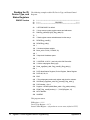
Where to Find it - Online and Printed Information:
System installation (hardware/software)............. VXIbus Configuration Guide*
Agilent VIC (VXI installation software)*
Module configuration and wiring........................ This Manual
SCPI programming.............................................. This Manual
SCPI example programs...................................... This Manual
SCPI command reference ................................... This Manual
Register-Based Programming ............................. This Manual
VXIplug&play programming ............................. VXIplug&play Online Help
VXIplug&play example programs...................... VXIplug&play Online Help
VXIplug&play function reference ...................... VXIplug&play Online Help
Soft Front Panel information............................... VXIplug&play Online Help
VISA language information ................................ Agilent VISA User’s Guide
Agilent VEE programming information ............. Agilent VEE User’s Manual
*Supplied with Agilent Command Modules, Embedded Controllers, and VXLink.
*E1328-90005*
Manual Part Number: E1328-90005
Printed in Malaysia E0912
Errata
Agilent References in this manual
NOTICE: This document contains references to Agilent Technologies. Agilent’s former Test and Measurement
business has become Keysight Technologies. For more information, go to:
www.keysight.com
About this manual
We’ve added this manual to the Keysight website in an effort to help you support your product. This manual
provides the best information we could find. It may be incomplete or contain dated information.
Support for your product
You can find information about technical and professional services, product support, and equipment repair and
service on the web:
www.keysight.com
Select your country from the drop-down menu at the top. Under Electronic Test and Measurement, click
on Services. The web page that appears next has contact information specific to your country.
For more detailed product information, go to: www.keysight.com/find/<product model>
i.e., for the M9514A, use: www.keysight.com/find/M9514A
Hypertext links to documents on agilent.com are no longer active. Use this substitution to access PDF files:
Broken links have the form: http://cp.literature.agilent.com/litweb/pdf/<literature_part_number>
Substitute links with this form: http://literature.cdn.keysight.com/litweb/pdf/<literature_part_number>
Where <literature_part_number> has the form: M9300-90001.pdf
For service notes, use: www.keysight.com/find/servicenotes
Contents
Agilent E1328B User’s Manual
Warranty . . . . . . . . . .
WARNINGS . . . . . . . .
Safety Symbols . . . . . .
Declaration of Conformity .
User’s Notes . . . . . . . .
.
.
.
.
.
.
.
.
.
.
.
.
.
.
.
.
.
.
.
.
.
.
.
.
.
.
.
.
.
.
.
.
.
.
.
.
.
.
.
.
.
.
.
.
.
.
.
.
.
.
.
.
.
.
.
.
.
.
.
.
.
.
.
.
.
.
.
.
.
.
.
.
.
.
.
.
.
.
.
.
.
.
.
.
.
.
.
.
.
.
.
.
.
.
.
.
.
.
.
.
.
.
.
.
.
.
.
.
.
.
.
.
.
.
.
.
.
.
.
.
.
.
.
.
.
.
.
.
.
.
.
.
.
.
.
.
.
.
.
.
.
.
.
.
.
.
.
.
.
.
.
.
.
.
.
.
.
.
.
.
5
6
6
7
8
Chapter 1. Getting Started with the Agilent E1328A . . . . . . . . . . . . . . . . . . . . . 11
Using This Chapter . . . . . . .
D/A Converter Description . . .
General Description . . . . .
Instrument Definition . . . . . .
Programming the D/A Converter
Selecting SCPI Commands .
.
.
.
.
.
.
.
.
.
.
.
.
.
.
.
.
.
.
.
.
.
.
.
.
.
.
.
.
.
.
.
.
.
.
.
.
.
.
.
.
.
.
.
.
.
.
.
.
.
.
.
.
.
.
.
.
.
.
.
.
.
.
.
.
.
.
.
.
.
.
.
.
.
.
.
.
.
.
.
.
.
.
.
.
.
.
.
.
.
.
.
.
.
.
.
.
.
.
.
.
.
.
.
.
.
.
.
.
.
.
.
.
.
.
.
.
.
.
.
.
.
.
.
.
.
.
.
.
.
.
.
.
.
.
.
.
.
.
.
.
.
.
.
.
.
.
.
.
.
.
.
.
.
.
.
.
.
.
.
.
.
.
.
.
.
.
.
.
.
.
.
.
.
.
11
11
11
12
13
13
Chapter 2. Configuring the Agilent E1328A . . . . . . . . . . . . . . . . . . . . . . . . . . 15
Using This Chapter . . . . . . . . .
Warnings and Cautions . . . . . . .
Setting the Logical Address Switch .
Selecting Voltage or Current Output
Connecting Field Wiring . . . . . .
Wiring Guidelines . . . . . . .
.
.
.
.
.
.
.
.
.
.
.
.
.
.
.
.
.
.
.
.
.
.
.
.
.
.
.
.
.
.
.
.
.
.
.
.
.
.
.
.
.
.
.
.
.
.
.
.
.
.
.
.
.
.
.
.
.
.
.
.
.
.
.
.
.
.
.
.
.
.
.
.
.
.
.
.
.
.
.
.
.
.
.
.
.
.
.
.
.
.
.
.
.
.
.
.
.
.
.
.
.
.
.
.
.
.
.
.
.
.
.
.
.
.
.
.
.
.
.
.
.
.
.
.
.
.
.
.
.
.
.
.
.
.
.
.
.
.
.
.
.
.
.
.
.
.
.
.
.
.
.
.
.
.
.
.
.
.
.
.
.
.
15
15
16
17
18
18
Chapter 3. Using the Agilent E1328A . . . . . . . . . . . . . . . . . . . . . . . . . . . . . . 19
Using This Chapter . . . . . . . . . . . . . . . . . . . . . . . . . . . . . . .
D/A Converter Commands . . . . . . . . . . . . . . . . . . . . . . . . . . .
Reset Conditions . . . . . . . . . . . . . . . . . . . . . . . . . . . . . . . . .
Electronic Voltage Adjustment . . . . . . . . . . . . . . . . . . . . . . . . .
Example: Electronic Voltage Adjustment Using a System Voltmeter . . .
Outputting Voltage . . . . . . . . . . . . . . . . . . . . . . . . . . . . . . .
Example: Voltage Output in Calibrated Mode . . . . . . . . . . . . . . .
Example: Voltage Output in Calibrated Mode with Remote Sensing . . .
Example: Expanding Voltage Output Range in the Calibrated Mode
with Remote Sensing . . . . . . . . . . . . . . . . . . . . . . . . . . .
Electronic Current Adjustment . . . . . . . . . . . . . . . . . . . . . . . . .
Example: One Channel Electronic Current Adjustment
Using an External Multimeter . . . . . . . . . . . . . . . . . . . . . .
Outputting Current . . . . . . . . . . . . . . . . . . . . . . . . . . . . . . . .
Example: One Channel Current Output in Calibrated Mode . . . . . . . .
Example: Expanding Current Output Range in the Non-Calibrated Mode
Agilent E1328A User’s Manual
.
.
.
.
.
.
.
.
.
.
.
.
.
.
.
.
.
.
.
.
.
.
.
.
.
.
.
.
.
.
.
.
.
.
.
.
.
.
.
.
19
19
19
20
21
23
23
24
. . . . . 24
. . . . . 26
.
.
.
.
.
.
.
.
.
.
.
.
.
.
.
.
.
.
.
.
27
29
29
29
Contents - 1
Chapter 4. Understanding the Agilent E1328A . . . . . . . . . . . . . . . . . . . . . . . . 31
Using This Chapter . . . . . . . . . . . . . . . . . . . .
Commands for D/A Converter Operation . . . . . . . . .
Voltage Output . . . . . . . . . . . . . . . . . . . . . . .
Remote Sense . . . . . . . . . . . . . . . . . . . . . . .
Maximum Lead Resistance . . . . . . . . . . . . . .
Operation with Fixed Voltage Sources in Series . . .
Adjustment Under Actual Lead and Load Conditions
Current Output . . . . . . . . . . . . . . . . . . . . . . .
Querying the D/A Converter . . . . . . . . . . . . . . .
.
.
.
.
.
.
.
.
.
.
.
.
.
.
.
.
.
.
.
.
.
.
.
.
.
.
.
.
.
.
.
.
.
.
.
.
.
.
.
.
.
.
.
.
.
.
.
.
.
.
.
.
.
.
.
.
.
.
.
.
.
.
.
.
.
.
.
.
.
.
.
.
.
.
.
.
.
.
.
.
.
.
.
.
.
.
.
.
.
.
.
.
.
.
.
.
.
.
.
.
.
.
.
.
.
.
.
.
.
.
.
.
.
.
.
.
.
.
.
.
.
.
.
.
.
.
.
.
.
.
.
.
.
.
.
.
.
.
.
.
.
.
.
.
31
31
32
33
33
34
34
36
37
Chapter 5. Agilent E1328A Command Reference . . . . . . . . . . . . . . . . . . . . . . . 39
Using This Chapter . . . . . . . . . . . . . . . .
Command Types . . . . . . . . . . . . . . . . . .
Common Command Format . . . . . . . .
SCPI Command Format . . . . . . . . . . .
Command Separator . . . . . . . . . . . .
Abbreviated and Short Commands . . . . .
Implied Commands . . . . . . . . . . . . .
Parameters . . . . . . . . . . . . . . . . .
Linking Commands . . . . . . . . . . . . . .
SCPI Command Reference . . . . . . . . . . . .
CALibration . . . . . . . . . . . . . . . . . . . .
CALibrationn:CURRent . . . . . . . . . . .
CALibrationn:STATe . . . . . . . . . . . . .
CALibrationn:STATe? . . . . . . . . . . . .
CALibrationn:VOLTage . . . . . . . . . . .
DISPlay . . . . . . . . . . . . . . . . . . . . . .
DISPlay:MONitor:CHANnel . . . . . . . . .
DISPlay:MONitor:CHANnel? . . . . . . . .
DISPlay:MONitor[:STATe] . . . . . . . . .
DISPlay:MONitor:STRing? . . . . . . . . .
[SOURce:] . . . . . . . . . . . . . . . . . . . . .
[SOURce:]CURRentn . . . . . . . . . . . .
[SOURce:]CURRentn? . . . . . . . . . . . .
[SOURce:]FUNCtionn? . . . . . . . . . . .
[SOURce:]VOLTagen . . . . . . . . . . . .
[SOURce:]VOLTagen? . . . . . . . . . . . .
SYSTem . . . . . . . . . . . . . . . . . . . . . .
SYSTem:ERRor? . . . . . . . . . . . . . . .
IEEE-488.2 Common Command Quick Reference
Agilent E1328A Command Quick Reference . . .
2 - Contents
Agilent E1328A User’s Manual
.
.
.
.
.
.
.
.
.
.
.
.
.
.
.
.
.
.
.
.
.
.
.
.
.
.
.
.
.
.
.
.
.
.
.
.
.
.
.
.
.
.
.
.
.
.
.
.
.
.
.
.
.
.
.
.
.
.
.
.
.
.
.
.
.
.
.
.
.
.
.
.
.
.
.
.
.
.
.
.
.
.
.
.
.
.
.
.
.
.
.
.
.
.
.
.
.
.
.
.
.
.
.
.
.
.
.
.
.
.
.
.
.
.
.
.
.
.
.
.
.
.
.
.
.
.
.
.
.
.
.
.
.
.
.
.
.
.
.
.
.
.
.
.
.
.
.
.
.
.
.
.
.
.
.
.
.
.
.
.
.
.
.
.
.
.
.
.
.
.
.
.
.
.
.
.
.
.
.
.
.
.
.
.
.
.
.
.
.
.
.
.
.
.
.
.
.
.
.
.
.
.
.
.
.
.
.
.
.
.
.
.
.
.
.
.
.
.
.
.
.
.
.
.
.
.
.
.
.
.
.
.
.
.
.
.
.
.
.
.
.
.
.
.
.
.
.
.
.
.
.
.
.
.
.
.
.
.
.
.
.
.
.
.
.
.
.
.
.
.
.
.
.
.
.
.
.
.
.
.
.
.
.
.
.
.
.
.
.
.
.
.
.
.
.
.
.
.
.
.
.
.
.
.
.
.
.
.
.
.
.
.
.
.
.
.
.
.
.
.
.
.
.
.
.
.
.
.
.
.
.
.
.
.
.
.
.
.
.
.
.
.
.
.
.
.
.
.
.
.
.
.
.
.
.
.
.
.
.
.
.
.
.
.
.
.
.
.
.
.
.
.
.
.
.
.
.
.
.
.
.
.
.
.
.
.
.
.
.
.
.
.
.
.
.
.
.
.
.
.
.
.
.
.
.
.
.
.
.
.
.
.
.
.
.
.
.
.
.
.
.
.
.
.
.
.
.
.
.
.
.
.
.
.
.
.
.
.
.
.
.
.
.
.
.
.
.
.
.
.
.
.
.
.
.
.
.
.
.
.
.
.
.
.
.
.
.
.
.
.
.
.
.
.
.
.
.
.
.
.
.
.
.
.
.
.
.
.
.
.
.
.
.
.
.
.
.
.
.
.
.
.
.
.
.
.
.
.
.
.
.
.
.
.
.
.
.
.
.
.
.
.
.
.
.
.
.
.
.
.
.
.
.
.
.
.
.
.
.
.
.
.
.
.
.
.
.
.
.
.
.
.
.
.
.
.
.
.
.
.
.
.
.
.
.
.
.
.
.
.
.
.
.
.
.
.
.
.
.
.
.
.
.
.
.
.
.
.
.
.
.
.
.
.
.
.
.
.
.
.
39
39
39
39
40
40
40
40
41
41
42
42
43
43
44
45
45
46
46
46
47
47
47
48
48
48
49
49
50
51
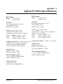
Appendix A. Agilent E1328A Specifications . . . . . . . . . . . . . . . . . . . . . . . . . . 53
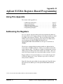
Appendix B. Agilent E1328A Register-Based Programming . . . . . . . . . . . . . . . . . 55
Using This Appendix . . . . . . . . . . . . . . . . . . . . . . . . . . . . . .
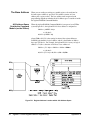
Addressing the Registers . . . . . . . . . . . . . . . . . . . . . . . . . . . .
The Base Address . . . . . . . . . . . . . . . . . . . . . . . . . . . . . .
A16 Address Space Outside the Command Module (on the VXIbus) .
A16 Address Space Inside the Agilent E1405/06 Command Module or
Agilent E1300/01 Mainframe . . . . . . . . . . . . . . . . . . . . .
Register Offset . . . . . . . . . . . . . . . . . . . . . . . . . . . . . . .
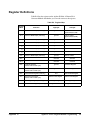
Register Definitions . . . . . . . . . . . . . . . . . . . . . . . . . . . . . . .
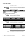
Register Descriptions . . . . . . . . . . . . . . . . . . . . . . . . . . . . . .
Manufacturer ID Register . . . . . . . . . . . . . . . . . . . . . . . . . .
Device Type Register . . . . . . . . . . . . . . . . . . . . . . . . . . . .
Status/Control Register . . . . . . . . . . . . . . . . . . . . . . . . . . .
Status Bit Precedence . . . . . . . . . . . . . . . . . . . . . . . . . .
Channel Mode Registers . . . . . . . . . . . . . . . . . . . . . . . . . .
Channel Output Registers . . . . . . . . . . . . . . . . . . . . . . . . . .
Command and Parameter Registers . . . . . . . . . . . . . . . . . . . .
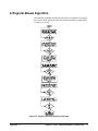
A Register-Based Algorithm . . . . . . . . . . . . . . . . . . . . . . . . . .
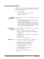
Programming Examples . . . . . . . . . . . . . . . . . . . . . . . . . . . . .
System Configuration . . . . . . . . . . . . . . . . . . . . . . . . . . . .
Resetting the Module . . . . . . . . . . . . . . . . . . . . . . . . . . . .
Reading the ID, Device Type, and Status Registers . . . . . . . . . . . .
Outputting a Voltage or Current . . . . . . . . . . . . . . . . . . . . . .
Using an Embedded Agilent RADI-EPC7 Computer . . . . . . . . . . .
.
.
.
.
.
.
.
.
.
.
.
.
.
.
.
.
.
.
.
.
55
55
56
56
.
.
.
.
.
.
.
.
.
.
.
.
.
.
.
.
.
.
.
.
.
.
.
.
.
.
.
.
.
.
.
.
.
.
.
.
.
.
.
.
.
.
.
.
.
.
.
.
.
.
.
.
.
.
.
.
.
.
.
.
.
.
.
.
.
.
.
.
.
.
.
.
.
.
.
.
.
.
.
.
.
.
.
.
.
.
.
.
.
.
57
58
59
60
60
60
60
61
63
63
64
71
72
72
72
74
76
79
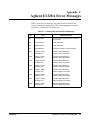
Appendix C. Agilent E1328A Error Messages . . . . . . . . . . . . . . . . . . . . . . . . . 83
Index . . . . . . . . . . . . . . . . . . . . . . . . . . . . . . . . . . . . . . . . . . . . . . . . 85
Agilent E1328A User’s Manual
Contents - 3
Notes
4 - Contents
Agilent E1328A User’s Manual
Certification
Agilent Technologies certifies that this product met its published specifications at the time of shipment from the factory. Agilent
Technologies further certifies that its calibration measurements are traceable to the United States National Institute of Standards and
Technology (formerly National Bureau of Standards), to the extent allowed by that organization’s calibration facility, and to the calibration
facilities of other International Standards Organization members.
Warranty
This Agilent Technologies product is warranted against defects in materials and workmanship for a period of one (1) year from date of
shipment. Duration and conditions of warranty for this product may be superseded when the product is integrated into (becomes a part
of) other Agilent products. During the warranty period, Agilent Technologies will, at its option, either repair or replace products which
prove to be defective.
For warranty service or repair, this product must be returned to a service facility designated by Agilent Technologies. Buyer shall prepay
shipping charges to Agilent and Agilent shall pay shipping charges to return the product to Buyer. However, Buyer shall pay all shipping
charges, duties, and taxes for products returned to Agilent from another country.
Agilent warrants that its software and firmware designated by Agilent for use with a product will execute its programming instructions
when properly installed on that product. Agilent does not warrant that the operation of the product, or software, or firmware will be
uninterrupted or error free.
Limitation Of Warranty
The foregoing warranty shall not apply to defects resulting from improper or inadequate maintenance by Buyer, Buyer-supplied products
or interfacing, unauthorized modification or misuse, operation outside of the environmental specifications for the product, or improper site
preparation or maintenance.
The design and implementation of any circuit on this product is the sole responsibility of the Buyer. Agilent does not warrant the Buyer’s
circuitry or malfunctions of Agilent products that result from the Buyer’s circuitry. In addition, Agilent does not warrant any damage that
occurs as a result of the Buyer’s circuit or any defects that result from Buyer-supplied products.
NO OTHER WARRANTY IS EXPRESSED OR IMPLIED. Agilent SPECIFICALLY DISCLAIMS THE IMPLIED WARRANTIES
OF MERCHANTABILITY AND FITNESS FOR A PARTICULAR PURPOSE.
Exclusive Remedies
THE REMEDIES PROVIDED HEREIN ARE BUYER’S SOLE AND EXCLUSIVE REMEDIES. Agilent SHALL NOT BE LIABLE
FOR ANY DIRECT, INDIRECT, SPECIAL, INCIDENTAL, OR CONSEQUENTIAL DAMAGES, WHETHER BASED ON CONTRACT, TORT, OR ANY OTHER LEGAL THEORY.
Notice
The information contained in this document is subject to change without notice. Agilent Technologies MAKES NO WARRANTY OF
ANY KIND WITH REGARD TO THIS MATERIAL, INCLUDING, BUT NOT LIMITED TO, THE IMPLIED WARRANTIES OF
MERCHANTABILITY AND FITNESS FOR A PARTICULAR PURPOSE. Agilent shall not be liable for errors contained herein or for
incidental or consequential damages in connection with the furnishing, performance or use of this material. This document contains
proprietary information which is protected by copyright. All rights are reserved. No part of this document may be photocopied, reproduced,
or translated to another language without the prior written consent of Agilent Technologies, Inc. Agilent assumes no responsibility for the
use or reliability of its software on equipment that is not furnished by Agilent.
U.S. Government Restricted Rights
The Software and Documentation have been developed entirely at private expense. They are delivered and licensed as "commercial
computer software" as defined in DFARS 252.227- 7013 (Oct 1988), DFARS 252.211-7015 (May 1991) or DFARS 252.227-7014 (Jun
1995), as a "commercial item" as defined in FAR 2.101(a), or as "Restricted computer software" as defined in FAR 52.227-19 (Jun 1987)(or
any equivalent agency regulation or contract clause), whichever is applicable. You have only those rights provided for such Software and
Documentation by the applicable FAR or DFARS clause or the Agilent standard software agreement for the product involved.
Agilent E1328A 4-Channel D/A Converter Module User’s Manual
Edition 5 Rev 3
Copyright © 1996-2006 Agilent Technologies, Inc. All Rights Reserved.
Agilent E1328A 4-Channel D/A Converter Module User’s Manual
5
Printing History
The Printing History shown below lists all Editions and Updates of this manual and the printing date(s). The first printing of the manual
is Edition 1. The Edition number increments by 1 whenever the manual is revised. Updates, which are issued between Editions, contain
replacement pages to correct the current Edition of the manual. Updates are numbered sequentially starting with Update 1. When a new
Edition is created, it contains all the Update information for the previous Edition. Each new Edition or Update also includes a revised copy
of this printing history page. Many product updates or revisions do not require manual changes and, conversely, manual corrections may
be done without accompanying product changes. Therefore, do not expect a one-to-one correspondence between product updates and
manual updates.
Edition 1 . . . . . . . . . . . . . . . . . . . . . . . . . . . . . . . . . . . . . . . . . . . September 1989
Edition 2 . . . . . . . . . . . . . . . . . . . . . . . . . . . . . . . . . . . . . . . . . . . . . . . . May 1992
Edition 3 . . . . . . . . . . . . . . . . . . . . . . . . . . . . . . . . . . . . . . . . . . . . February 1994
Edition 4 . . . . . . . . . . . . . . . . . . . . . . . . . . . . . . . . . . . . . . . . . . . . . . . April 1995
Edition 5 (Part Number E1328-90005). . . . . . . . . . . . . . . . . . . . November 1996
Edition 5 Rev 2 (Part Number E1328-90005) . . . . . . . . . . . . . . . . . . . May 2006
Edition 5 Rev 3 (Part Number E1328-90005) . . . . . . . . . . . . . . September 2012
Safety Symbols
Instruction manual symbol affixed to product.
Indicates that the user must refer to the manual for specific WARNING or CAUTION
information to avoid personal injury or damage to the product.
Indicates the field wiring terminal that must
be connected to earth ground before operating
the equipment—protects against electrical
shock in case of fault.
or
Frame or chassis ground terminal—typically
connects to the equipment’s metal frame.
Alternating current (AC).
Direct current (DC).
Indicates hazardous voltages.
WARNING
CAUTION
Calls attention to a procedure, practice, or condition that could cause bodily injury or death.
Calls attention to a procedure, practice, or condition that could possibly cause damage to
equipment or permanent loss of data.
WARNINGS
The following general safety precautions must be observed during all phases of operation, service, and repair of this product.
Failure to comply with these precautions or with specific warnings elsewhere in this manual violates safety standards of design,
manufacture, and intended use of the product. Agilent Technologies assumes no liability for the customer’s failure to comply with
these requirements.
Ground the equipment: For Safety Class 1 equipment (equipment having a protective earth terminal), an uninterruptible safety earth
ground must be provided from the mains power source to the product input wiring terminals or supplied power cable.
DO NOT operate the product in an explosive atmosphere or in the presence of flammable gases or fumes.
For continued protection against fire, replace the line fuse(s) only with fuse(s) of the same voltage and current rating and type.
DO NOT use repaired fuses or short-circuited fuse holders.
Keep away from live circuits: Operating personnel must not remove equipment covers or shields. Procedures involving the removal of
covers or shields are for use by service-trained personnel only. Under certain conditions, dangerous voltages may exist even with the
equipment switched off. To avoid dangerous electrical shock, DO NOT perform procedures involving cover or shield removal unless you
are qualified to do so.
DO NOT operate damaged equipment: Whenever it is possible that the safety protection features built into this product have been
impaired, either through physical damage, excessive moisture, or any other reason, REMOVE POWER and do not use the product until
safe operation can be verified by service-trained personnel. If necessary, return the product to an Agilent Technologies Sales and Service
Office for service and repair to ensure that safety features are maintained.
DO NOT service or adjust alone: Do not attempt internal service or adjustment unless another person, capable of rendering first aid and
resuscitation, is present.
DO NOT substitute parts or modify equipment: Because of the danger of introducing additional hazards, do not install substitute parts
or perform any unauthorized modification to the product. Return the product to an Agilent Technologies Sales and Service Office for
service and repair to ensure that safety features are maintained.
6
Agilent E1328A 4-Channel D/A Converter Module User’s Manual
Declaration of Conformity
Declarations of Conformity for this product and for other Agilent products may be downloaded from the Internet. There are two methods to obtain
the Declaration of Conformity:
•
Go to http://regulations.corporate.agilent.com/DoC/search.htm. You can then search by product number to find the latest Declaration
of Conformity.
• Alternately, you can go to the product web page (www.agilent.com/find/E1328A), click on the Document Library tab then
scroll down until you find the Declaration of Conformity link.
Notes
8
Agilent E1328A 4-Channel D/A Converter Module User’s Manual
Notes
Agilent E1328A 4-Channel D/A Converter Module User’s Manual
9
Notes
10
Agilent E1328A 4-Channel D/A Converter Module User’s Manual
Chapter 1
Getting Started with the Agilent E1328A
Using This Chapter
This chapter describes the Agilent E1328A 4-Channel D/A Converter
module, and contains information on how to program it using SCPI
(Standard Commands for Programmable Instruments) commands. This
chapter contains the following sections:
• D/A Converter Description . . . . . . . . . . . . . . . . . . . . . . . . . . Page 11
• Instrument Definition. . . . . . . . . . . . . . . . . . . . . . . . . . . . . . . Page 12
• Programming the D/A Converter. . . . . . . . . . . . . . . . . . . . . . Page 13
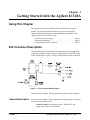
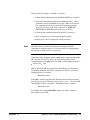
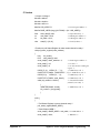
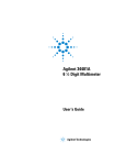
D/A Converter Description
The Agilent E1328A 4-Channel D/A Converter provides four independent,
16-bit isolated digital-to-analog channels configurable for either DC voltage
or DC current output. Figure 1-1 shows a block diagram for one of the four
Figure 1-1. D/A Converter Block Diagram
Agilent E1328A channels. All four channels have the same block diagram.
General Description
Each of the four channels can be programmed to output voltage or current in
one of the two operating modes.
– Calibrated mode: output voltage range is ±10.922 Vdc and
output current range is ±21.84 mAdc.
Chapter 1
Getting Started with the Agilent E1328A
11
– Non-calibrated mode: output range is typically ±12 Vdc
and ±24 mAdc.
In the calibrated mode, output accuracy is dependent on the date of the last
electronic adjustment performed (see Appendix A). This accuracy is
maintained by use of stored adjustment constants in memory. Each channel
has independent adjustment constants for both voltage and current, which
are updated by performing the appropriate electronic adjustment procedure
(see Chapter 3).
The electronic adjustment procedures used to update the channel’s stored
voltage and/or current adjustment constant in memory requires only a
multimeter (51⁄2-digit, 0.015% of reading + 1 mV accuracy) to complete. If
a system multimeter is used, the electronic adjustment procedures can also
be automated.
The four channels are electrically isolated from each other, and from chassis
ground. This allows the usable output range (voltage and/or current) to be
expanded by linking multiple channels. For example, the output voltage range
can be expanded to 48 Vdc by linking channels in series, and the output current
range can be expanded to 96 mAdc by linking channels in parallel.
Both voltage and current outputs on all channels are provided with output
short circuit protection. Additionally, each channel configured for
outputting voltage has no-fault remote-sensing capability to ensure accurate
voltages at the load. If one of the sense leads become disconnected, the
D/A Converter will automatically revert to local sensing.
The AC FAIL line (from the mainframe) is constantly monitored by the
D/A Converter. If power fails, the D/A Converter channels are shut down
to conserve power and provide greater hold-up time for the mainframe
power supplies.
Instrument Definition
Agilent plug-in modules installed in an Agilent mainframe are treated as
independent instruments, each having a unique secondary GPIB address.
Each instrument is also assigned a dedicated error queue, input and output
buffers, status registers and, if applicable, dedicated mainframe memory
space for readings or data. An instrument may be composed of a single
plug-in module (such as a counter) or multiple plug-in modules (for a
switchbox or scanning voltmeter instrument).
12
Getting Started with the Agilent E1328A
Chapter 1
Programming the D/A Converter
To program the D/A Converter using Standard Commands for Programmable
Instruments (SCPI), you must select the controller language, interface address,
and SCPI commands to be used. See Installing the Agilent E1300B/E1301B
Mainframe and Plug-In Modules Configuration Guide for interface addressing
and controller language information.
Note
Selecting SCPI
Commands
This discussion applies to SCPI programming. See Appendix B for details
on register-based programming.
A SCPI command consists of a keyword, such as the source command
[SOURce:]VOLTagen <level>. n defines the channel to be configured
(for voltage in this case). Most keywords require that you specify the channel
(1, 2, 3, or 4) you want to act on. If no channel is specified, the default is
channel 1.
Some keywords must be followed by a value to set a parameter to a specific
value (for example, voltage level, [SOURce:]VOLTage1 10.00000).
"10.00000" outputs +10.00000 Vdc on channel 1 if properly configured for
voltage. Additionally, some keywords must be followed by a value to set a
parameter to a specific state (for example, calibration on/off CAL:STAT 1).
The "1" sets the D/A Converter channel 1 mode to ON (calibration).
Note
Chapter 1
Implied commands are those which appear in square brackets ([ ]) in the
command syntax. The brackets are not part of the command and are not
sent to the instrument. [SOURce:] is an implied command and, therefore, is
not required. See page 40 for more information about implied commands.
Getting Started with the Agilent E1328A
13
Notes
14
Getting Started with the Agilent E1328A
Chapter 1
Chapter 2
Configuring the Agilent E1328A
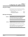
Using This Chapter
This chapter shows how to connect external wiring to the 4-Channel D/A
Converter module inputs, and how to configure the module for voltage and
current output. This chapter contains the following sections:
•
•
•
•
Warnings and Cautions . . . . . . . . . . . . . . . . . . . . . . . . . . . . .
Setting the Logical Address Switch. . . . . . . . . . . . . . . . . . . .
Selecting Voltage or Current Output . . . . . . . . . . . . . . . . . . .
Connecting Field (user) Wiring . . . . . . . . . . . . . . . . . . . . . . .
Page 15
Page 16
Page 17
Page 18
Warnings and Cautions
WARNING
CAUTION
SHOCK HAZARD. Only service-trained personnel who are aware of
the hazards involved should install, remove, or configure the D/A
Converter module. Before you remove any installed module,
disconnect AC power from the mainframe and field wiring.
MAXIMUM VOLTAGE. The maximum voltage that may be applied
between any two terminals within the same channel is 15 Vdc. Do not apply
voltage between any pair of terminals if the D/A Converter is turned off.
STATIC ELECTRICITY. Static electricity is a major cause of component
failure. To prevent damage to the electrical components in the D/A
Converter module, observe anti-static techniques whenever removing a
module from the mainframe or whenever working on a module.
Chapter 2
Configuring the Agilent E1328A
15
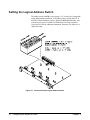
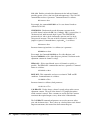
Setting the Logical Address Switch
The address switch (LADDR) factory setting is 72. You may have changed the
setting during module installation. Valid address values are from 0 to 255. If
the D/A Converter module is used in a Agilent E1300/E1301 Mainframe, refer
to Installing the Agilent E1300B/E1301B Mainframe and Plug-In Modules
Configuration Guide for addressing information. Otherwise, use Figure 2-1 to
change the setting.
Figure 2-1. Locate and Set the Logical Address Switch
16
Configuring the Agilent E1328A
Chapter 2
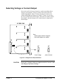
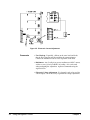
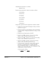
Selecting Voltage or Current Output
Each of the four D/A Converter channels is capable of providing either a
voltage or current output. Voltage or current can be selected for each
channel independently. Figure 2-2 shows the jumper location for each
channel and highlights the jumpers for Channel 1. Figure 2-2 also shows
the correct position for the desired output. Note that each channel contains
three jumpers, and that all jumpers for a channel must be changed to the
desired output.
Note:
All three jumpers must be configured
to the same output for any channel.
Set to Voltage
Set to Current
Figure 2-2. Voltage/Current Output Selection
CAUTION
Chapter 2
Moving the V/I jumpers with power applied to the D/A Converter could
cause improper operation or damage.
Configuring the Agilent E1328A
17
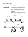
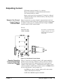
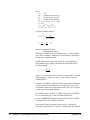
Connecting Field Wiring
Figure 2-3 shows the input terminals for the D/A Converter output and
sense terminals. Use the following guidelines for wire connections.
Wiring Guidelines
• It is recommended that each channel wire be identified (color coded or
marked) as the connection is not visible when the D/A Converter
module is installed.
• Be sure that wires make good connections on the screw terminals.
• Maximum wire size is 16 AWG. Wire ends should be stripped 6 mm
(≈0.234 inch) and tinned to prevent single strands from shorting
adjacent terminals.
• The other end may have any connection the user determines necessary.
• Do not connect the channel’s SENSE terminals if they will not be
used (for example, channel is being configured for a current output,
or a voltage output without remote sensing).
Figure 2-3. D/A Converter Terminals
18
Configuring the Agilent E1328A
Chapter 2
Chapter 3
Using the Agilent E1328A
Using This Chapter
This chapter uses typical examples to show how to use the 4-Channel D/A
Converter. Refer to Chapter 4, “ Understanding the Agilent E1328A” , for
more information. This chapter contains the following:
•
•
•
•
•
•
D/A Converter Commands . . . . . . . . . . . . . . . . . . . . . . . . . .
Reset Conditions . . . . . . . . . . . . . . . . . . . . . . . . . . . . . . . . . .
Electronic Voltage Adjustment . . . . . . . . . . . . . . . . . . . . . . .
Outputting Voltage. . . . . . . . . . . . . . . . . . . . . . . . . . . . . . . . .
Electronic Current Adjustment . . . . . . . . . . . . . . . . . . . . . . .
Outputting Current . . . . . . . . . . . . . . . . . . . . . . . . . . . . . . . . .
Page 19
Page 19
Page 20
Page 23
Page 26
Page 29
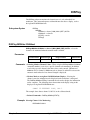
D/A Converter Commands
Table 3-1. D/A Converter Commands Used in Chapter 3
Command **
Description
CAL:CURRn z,z,z
Used during the current electronic adjustment procedure to update a channel’s stored
adjustment constants in memory.
CALn:STAT y
Selects calibrated (ON | 1) or non-calibrated mode (OFF | 0).
CAL:VOLTn z,z,z
Used during the voltage electronic adjustment procedure to update a channel’s stored
adjustment constants in memory.
[SOURce:]CURRn xxx
Causes the D/A Converter to output a specific current. Channel must be configured for current
output (refer to page 17). Range is dependent on the mode selected.
[SOURce:]VOLTn xxx
Causes the D/A Converter to output a specific voltage. Channel must be configured for voltage
output (refer to page 17). Range is dependent on the mode selected.
*RST
Sets the hardware and software to a known state.
** n = channel number, xxx = desired value, y = ON (1) or OFF (0), and z,z,z = measured minimum, default (0),
and maximum values. [SOURce:] is a command that is implied (not required), but if it is used, delete the brackets
and send as SOURce:.
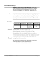
Reset Conditions
When the D/A Converter is switched on or *RST (reset), all four channels
are set to 0 Vdc/0 mAdc output (±100 ms.) and the calibrated mode is
selected for all channels. Refer to Chapter 4 for more information.
Chapter 3
Using the Agilent E1328A
19
Electronic Voltage Adjustment
The electronic voltage adjustment is used to update the stored voltage
constants for each channel, and should be performed:
– on initial set-up;
– periodically (24 hours or 90 days) to maintain desired output
accuracy (see Appendix A);
– when a ±5°C change in temperature from last adjustment performed
has occurred;
– when the type of load is changed;
– or anytime accuracy is in doubt.
The adjustment procedure is performed for each channel as follows:
1. Configure the desired channel(s) for voltage output (see page 17).
2. Connect the load to the desired D/A Converter channel. Connect a
voltmeter (external or system) to measure voltage at the load.
3. Set the D/A Converter channel to the non-calibrated mode.
Note
The electronic adjustment must be performed in the non-calibrated mode
(step 3), or errors in the adjustment constant will occur.
4. Set the channel’s output to minimum (–12 volts). Measure and
record to 51⁄2-digits the actual output at the load.
5. Set the channel’s output to default (0 volts). Measure and record to
51⁄2-digits the actual output at the load.
6. Set the channel’s output to maximum (+12 volts). Measure and
record to 51⁄2-digits the actual output at the load.
7. Record minimum, default, and maximum values and send them to the
module as arguments of the CALibration command. New adjustment
constants will be automatically calculated and stored from the
entered measurement values.
8. Repeat steps 2 through 7 for all desired channels.
20
Using the Agilent E1328A
Chapter 3
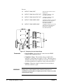
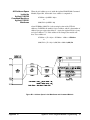
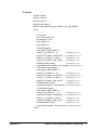
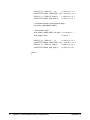
Example: Electronic
Voltage Adjustment
Using a System
Voltmeter
Figure 3-1 shows how to connect channel 1 output terminals to the load and
system voltmeter (Agilent E1326B/E1411B). The D/A Converter must be
physically configured to provide voltage output on channel 1 (refer to page 17),
and then instructed to perform the adjustment. For the example, use:
– An GPIB select code of 7, primary address of 09, and secondary
address of 09 for the D/A Converter.
– An GPIB select code of 7, primary address of 09, and secondary
address of 03 for the system voltmeter.
– An HP Series 200/300 Computer with BASIC.
Figure 3-1. Electronic Voltage Adjustment
Execute:
10
20
REAL A,B,C
OUTPUT 70909;"*RST"
30
OUTPUT 70909;"CAL1:STAT OFF"
!Reset the D/A Converter to its
default state; perform self-test.
!Configure channel 1 to the
non-calibrated mode.
40
OUTPUT 70909;"VOLT1 MIN"
!Configure channel 1 to output
the minimum voltage (-12 volts).
50
OUTPUT 70909;"*OPC?"
!Hold program execution until
the first output is complete. When
done, generate an operation
complete flag.
60
ENTER 70909;D
!Dummy variable holds
operation complete flag.
70
OUTPUT 70903;"MEAS:VOLT:DC?" !Configure the system voltmeter to
make a DC voltage measurement.
80
ENTER 70903;A
!Store minimum voltage reading.
90
OUTPUT 70909;"VOLT1 DEF"
!Configure channel 1 to output
the default voltage (0 volts).
100
OUTPUT 70903;"MEAS:VOLT:DC?" !Configure the system voltmeter to
make a DC voltage measurement.
Chapter 3
Using the Agilent E1328A
21
110
120
130
140
150
Comments
ENTER 70903;B
OUTPUT 70909;"VOLT1 MAX"
!Store default voltage reading.
!Configure channel 1 to output
the maximum voltage (+12 volts).
OUTPUT 70903;"MEAS:VOLT:DC?" !Configure the system voltmeter
for a DC voltage measurement.
ENTER 70903;C
!Store maximum voltage reading.
OUTPUT 70909;"CAL1:VOLT" ;A;B;C!Enter the measured minimum,
default, and maximum values.
New adjustment constants are
calculated and stored for
channel 1.
• Test Hook-up. If possible, calibrate to the same load (and leads)
that the D/A Converter will be providing the voltage output to.
Connect the voltmeter leads as close as possible to the load.
• Voltmeter. Any 51⁄2-digit voltmeter with accuracy of at least
(0.015% of reading +1mV) can be used when performing the
adjustment. Agilent recommends using the Agilent E1326B/E1411B
51⁄2-Digit Multimeter for a system voltmeter, or the Agilent 3457 for
an external voltmeter (recommended for current).
• Electronic Current Adjustment. If a channel is only to be used for
voltage output, it is not necessary to perform the current adjustment.
22
Using the Agilent E1328A
Chapter 3
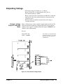
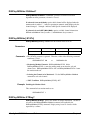
Outputting Voltage
– Will output voltage on channels 1, 2, 3, and/or 4.
– Range is 10.922 Vdc in calibrated mode and 12 Vdc in
non-calibrated mode per channel.
– Range can be increased to a maximum of 43.600 Vdc in calibrated
mode and 48 Vdc in non-calibrated mode by connecting all four
channels in series.
– Remote sensing is available to ensure the selected voltage is
available at the load.
Example: Voltage
Output in Calibrated
Mode
Figure 3-2 shows how to connect channel 1 output terminals to the load. The
D/A Converter must be physically configured to provide voltage output on
channel 1 (refer to page 17), and then instructed to output +10.00000 Vdc on
channel 1 in the calibrated mode.
Execute:
CAL1:STAT ON
VOLT1 10.00000
Sets channel 1 to calibrated mode.
Configures channel 1 for voltage
and sets output at terminals to
10.00000 Vdc.
Figure 3-2. One Channel Voltage Output
Chapter 3
Using the Agilent E1328A
23
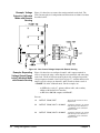
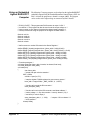
Example: Voltage
Output in Calibrated
Mode with Remote
Sensing
Figure 3-3 shows how to connect the sensing terminals to the load. The
D/A Converter physical configuration and instructions are identical to those
described earlier.
Figure 3-3. One Channel Voltage Output with Remote Sensing
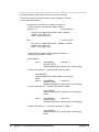
Example: Expanding
Voltage Output Range
in the Calibrated Mode
with Remote Sensing
Figure 3-4 shows how to configure channel 1 and 2 output terminals in
series to increase the range, connecting the sense terminals, and connecting
to the load. The D/A Converter must be physically configured to provide
voltage output on channels 1 and 2 (refer to page 17), and then instructed to
output a specific voltage on channels 1 and 2 in order to obtain a total of
+20.00000 Vdc in the calibrated mode. For the example, use:
– an GPIB select code of 7, primary address of 09, and secondary
address of 09 for the D/A Converter;
– an HP Series 200/300 computer with BASIC.
Execute:
24
10
OUTPUT 70909;"*RST"
20
OUTPUT 70909;"VOLT1 10.00000"
30
OUTPUT 70909;"VOLT2 10.00000"
Using the Agilent E1328A
!Reset the D/A Converter to its
default state.
!Configure channel 1 for voltage
and sets output at terminals to
+10.00000 V in the calibrated
(default) mode.
!Configure channel 2 for voltage
and sets output at terminals to
+10.00000 V in the calibrated
(default) mode.
Chapter 3
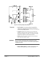
Figure 3-4. Extending Voltage Output Range
Comments
• Sense Terminals. Use of remote sensing is recommended to
compensate for voltage drops in the test leads. This ensures an
accurate voltage is present at the load. If not in use, do not make any
connection to the SENSE terminals.
• Compliance Current. The maximum current available when
outputting a voltage is 24 mAdc. This means, that at 12 Vdc, the
load resistance should be at least 500Ω. See Chapter 4 for further
explanation on compliance current and load resistance.
• Isolation. Channel-to-channel or channel-to-chassis isolation is
rated at 250 Vrms (350 Vdc/ac peak).
WARNING
Do not exceed the rated isolation voltage. Damage may result if
channels of the same D/A Converter are connected to separate phases
of 3-phase power lines.
• Incorrect Jumper Setting. If a channel is configured for current
and instructed to output voltage, an error will be generated.
Chapter 3
Using the Agilent E1328A
25
Electronic Current Adjustment
The electronic current adjustment is used to update the stored current
constants for each channel, and should be performed:
– on initial set-up;
– periodically (24 hours or 90 days) to maintain desired output
accuracy (see Appendix A);
– when a ±5°C change in temperature from last adjustment performed
has occurred;
– when the type of load is changed;
– or anytime accuracy is in doubt.
The adjustment procedure is performed for each channel as follows:
1. Configure the desired channel(s) for current output
(refer to page 17).
2. Connect the load to the desired D/A Converter channel.
Connect a multimeter to measure current at the load.
3. Set the D/A Converter channel to the non-calibrated mode.
Note
The electronic adjustment must be performed in the non-calibrated mode
(step 3), or errors in the adjustment constant will occur.
4. Set the channel’s output to minimum (–24 mAdc). Measure and
record to 51⁄2-digits the actual output at the load.
5. Set the channel’s output to default (0 mAdc). Measure and record to
51⁄2-digits the actual output at the load.
6. Set the channel’s output to maximum (+24 mAdc). Measure and
record to 51⁄2-digits the actual output at the load.
7. Record the minimum, default, and maximum values and send them as
parameters to the CALibration command. New adjustment constants
will be calculated and stored from the entered values.
8. Repeat steps 2 through 7 for all desired channels.
26
Using the Agilent E1328A
Chapter 3
Example: One Channel
Electronic Current
Adjustment Using an
External Multimeter
Figure 3-5 shows how to connect channel 1 output terminals to the load and
external multimeter (Agilent 3457A). The D/A Converter must be
physically configured to provide current output on channel 1 (refer to page
17), and then instructed to perform the adjustment. For the example, use:
– An GPIB select code of 7, primary address of 09, and secondary
address of 09 for the D/A Converter.
– An HP Series 200/300 computer with BASIC.
Execute:
10
REAL A,B,C,
20
OUTPUT 70909;"*RST"
30
OUTPUT 70909;"CAL1:STAT OFF"
40
50
60
70
80
90
100
110
120
130
Chapter 3
!Define variables used to store
measured values.
!Reset the D/A Converter to its
default state and performs a
self-test.
!Configure channel 1 to the
non-calibrated mode.
OUTPUT 70909;"CURR1 MIN"
!Configure channel 1 to output the
minimum current (–24 mAdc).
PRINT “RECORD AS MINIMUM”
!Message on screen instructs to
record the measurement on the
multimeter as minimum.
INPUT “ENTER RECORDED MIN: ”,A !Message on screen instructs to
enter the recorded minimum
value. Enter and press RETURN.
OUTPUT 70909;"CURR1 DEF"
!Configure channel 1 to output
the default current (0 mAdc).
PRINT “RECORD AS DEFAULT”
!Message on screen instructs to
record the measurement on the
multimeter as default.
INPUT “ENTER RECORDED DEF: ”,B !Message on screen instructs to
enter the recorded default value.
Enter and press RETURN.
OUTPUT 70909;"CURR1 MAX"
!Configure channel 1 to output the
maximum current (+24 mAdc).
PRINT “RECORD AS MAXIMUM”
!Message on screen instructs to
record the measurement on the
multimeter as maximum.
INPUT “ENTER RECORDED MAX: ”,C!Message on screen instructs to
enter the recorded maximum
value. Enter and press RETURN.
OUTPUT 70909; “CAL1:CURR ”;A;B;C,!Enter the measured minimum,
default, and maximum values.
New adjustment constants are
then calculated and stored for
channel 1.
Using the Agilent E1328A
27
Figure 3-5. Electronic Current Adjustment
Comments
• Test Hook-up. If possible, calibrate to the same load (and leads)
that the D/A Converter will be providing the current output to.
Connect the multimeter leads as close as possible to the load.
• Multimeter. Any 51⁄2-digit (or greater) multimeter with DC current,
with an accuracy of at least (0.02% of reading +1A) can be used
when performing the adjustment. Agilent recommends using the
Agilent 3457A.
• Electronic Voltage Adjustment. If a channel is only to be used for
current output, it is not necessary to perform the voltage adjustment.
28
Using the Agilent E1328A
Chapter 3
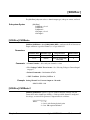
Outputting Current
– Will output current on channels 1, 2, 3, and/or 4.
– Range is 21.844 mAdc in calibrated mode and 24 mAdc in
non-calibrated mode per channel.
– Range can be increased to a maximum 87.376 mAdc in calibrated
mode and 96 mAdc in non-calibrated mode by connecting all four
channels in parallel.
Example: One Channel
Current Output in
Calibrated Mode
Figure 3-6 shows how to connect channel 1 output terminals to the load.
The D/A Converter must be physically configured to provide current output
on channel 1 (refer to page 17), and then instructed to output +20.00000
mAdc on channel 1 in the calibrated mode.
Execute:
CAL1:STAT ON
CURR1 0.020000
Sets channel 1 to calibrated mode.
Configures channel 1 for current
and sets output at terminals to
20.000 mAdc.
Figure 3-6. One Channel Current Output
Example: Expanding
Current Output Range
in the Non-Calibrated
Mode
Figure 3-7 shows how to configure channel 1 and 2 output terminals in
parallel to increase the range, and how to connect to the load. The D/A
Converter must be physically configured to provide current output on
channels 1 and 2 (refer to page 17), and then instructed to output a specific
current on channels 1 and 2 in order to obtain a total of +48.00000 mAdc in
the non-calibrated mode. For the example, use:
– An GPIB select code of 7, primary address of 09, and secondary
address of 09 for the D/A Converter.
– An HP Series 200/300 computer with BASIC.
Chapter 3
Using the Agilent E1328A
29
Execute:
10
OUTPUT 70909;"*RST"
20
OUTPUT 70909;"CAL1:STAT OFF"
30
OUTPUT 70909;"CAL2:STAT OFF"
40
OUTPUT 70909;"CURR1 MAX"
50
OUTPUT 70909;"CURR2 MAX"
!Reset the D/A Converter to its
default state.
!Configure channel 1 to the
non-calibrated mode.
!Configure channel 2 to the
non-calibrated mode.
!Configure channel 1 for current
and sets output at terminals to
maximum (+24 mAdc) in
non-calibrated mode.
!Configure channel 2 for current
and sets output at terminals to
maximum (+24 mAdc) in
non-calibrated mode.
Figure 3-7. Extending Current Output Range
• Sense Terminals. Do not make any connection to the SENSE
Comments
terminals when outputting current.
• Compliance Voltage. The maximum voltage available when
outputting a current from one channel is 13 Vdc. This means that at
24 mAdc, the load resistance should not exceed 541. See Chapter 4
for further explanation on compliance voltage and load resistance.
• Isolation. Channel-to-channel or channel-to-chassis isolation is
250 Vrms (350 Vdc/ac peak).
WARNING
30
Damage may result if channels of the same D/A Converter are
connected to separate phases of 3-phase power lines. Do not exceed the
rated isolation voltage.
Using the Agilent E1328A
Chapter 3
Chapter 4
Understanding the Agilent E1328A
Using This Chapter
This chapter explains techniques to output voltage and current levels using
the 4-Channel D/A Converter. This chapter contains the following sections:
•
•
•
•
•
Commands for D/A Converter Operation . . . . . . . . . . . . . . .
Voltage Output . . . . . . . . . . . . . . . . . . . . . . . . . . . . . . . . . . . .
Remote Sense . . . . . . . . . . . . . . . . . . . . . . . . . . . . . . . . . . . . .
Current Output . . . . . . . . . . . . . . . . . . . . . . . . . . . . . . . . . . . .
Querying the D/A Converter . . . . . . . . . . . . . . . . . . . . . . . . .
Page 31
Page 32
Page 33
Page 36
Page 37
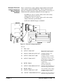
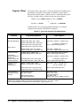
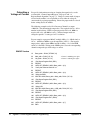
Commands for D/A Converter Operation
Outputting voltages and currents from the D/A Converter consists of
configuring the hardware for the type of output desired, then selecting the
output type, level, and mode. When necessary, an electronic adjustment is
performed to maintain calibrated mode output accuracy.
Figure 4-1. D/A Converter Commands
Chapter 4
Understanding the Agilent E1328A
31
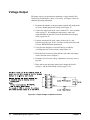
Voltage Output
The proper sequence of operation for outputting a voltage from the D/A
Converter is provided below. Refer, as necessary, to Chapters 2 and 3 for
additional operating information.
1. Determine the number of voltage outputs required, and configure the
necessary channel jumpers for voltage (refer to page 17).
2. Connect the output leads to the correct channel V/I + and - terminals
(refer to page 18). If extending the output range, connect the
required number of channels in series to obtain the desired output
(refer to pages 24–25).
3. If remote sensing will be used, connect leads to the S + and terminals (refer to pages 24–25). If remote sensing will not be used,
leave the SENSE terminals disconnected.
4. Verify that the compliance current will not be exceeded by
calculating the total circuit resistance using Figure 4-2.
5. Install the D/A Converter in the mainframe and connect the output
leads to the load (refer to Chapter 3).
6. Determine if an electronic voltage adjustment is necessary (refer to
page 20).
7. Enter and execute the proper instructions to output the desired
voltage(s), and the desired mode (refer to pages 23–25).
Figure 4-2. Output Voltage Compliance Current
32
Understanding the Agilent E1328A
Chapter 4
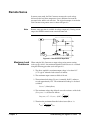
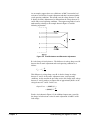
Remote Sense
In remote sense mode, the D/A Converter measures the actual voltage
delivered at the load, then compensates for any difference between the
measured value and the selected value. The equivalent output circuit for the
D/A Converter using remote sense is shown in Figure 4-3.
Note
Remote sense operation is available for voltage output only. During current
output, the SENSE terminals must remain disconnected.
Figure 4-3. Remote Sense Operation
Maximum Lead
Resistance
When using the D/A Converter to output voltage using remote sensing
(refer to pages 24–25), the maximum allowable lead resistance is calculated
using the following procedure (refer to Figure 4-3):
1. The driver amplifier’s maximum output voltage is less than 19 V
(17 V typical) when the load resistance is infinite.
2. The maximum output current available is 24 mA.
3. The maximum load voltage (VL(max)) is normally 10.92 V, and never
exceeds approximately 12 V. The maximum load voltage is calculated
as follows:
VL(max) ≤ (24mA)(Rload)
4. The maximum voltage drop allowed across the resistance of the leads
(Vdrop (max) ) is calculated as follows:
é VL(max) ù
Vdrop(max) = 17 − VL(max) − (101Ω) ê
ú
ë Rload û
5. Therefore the maximum allowable lead resistance (Rlead ) is:
Rlead ≤
Chapter 4
Vdrop(max)
R
VL(max) load
Understanding the Agilent E1328A
33
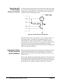
Operation with
Fixed Voltage
Sources in Series
If a fixed voltage must be placed in series with the load, connect the voltage
source to the V+ lead for the most accurate output. An example of this type
of application is shown in Figure 4-4. The emitter follower configuration
increases the total available output current.
Figure 4-4. Emitter Follower Configuration
If the fixed voltage source is placed in the V- lead, a small error will occur
in the output voltage. An output error of approximately 0.05% of the
voltage between V- and S- occurs due to the 51Ω protection resistor in
series with the S- terminal. This error does not occur if the voltage between
V- and S- is due solely to lead resistance, provided that an electronic
adjustment has been performed with the same load and lead configuration as
under actual operating conditions.
Adjustment Under
Actual Lead and
Load Conditions
Whenever possible, perform electronic adjustments with the D/A Converter
connected to the leads and load to be used in operation. An electronic
adjustment performed under actual operating conditions provides the best
output accuracy.
If an electronic adjustment is performed with a different V- lead resistance than
that encountered under actual operating conditions, small errors will occur in
the output voltage due to the effect of the 51Ω protection resistor mentioned in
the preceding section, “Operation with Fixed Voltage Sources in Series”.
34
Understanding the Agilent E1328A
Chapter 4
As an example, suppose there was a difference of 100Ω between the lead
resistances used for the electronic adjustment and those encountered under
actual operating conditions. This would cause the voltage between V- and
S- during electronic adjustment to be different than the voltage between Vand S- under actual operating conditions. The output error produced can be
understood by referring to the example shown in Figure 4-5 and the
following explanation.
Figure 4-5. Lead Resistance and Electronic Adjustment
R- is the change in lead resistance. The difference in voltage drop across Rbetween the electronic adjustment and actual operating conditions is as
follows:
VS− = VL
R−
RL
This difference in voltage drop across R- is also the change in voltage
between V- and S- for electronic adjustment versus actual operating
conditions. As discussed in the preceding section, this change in the voltage
between V- and S- produces an output error of approximately 0.05% of the
voltage between V- and S-. In this case:
Output Error = (0.0005)(VS−)
R−
= (0.0005) VL
RL
For the circuit shown in Figure 4-5, the additional output error (caused by
the change in lead resistance after electronic adjustment) is 0.005% of the
load voltage.
Chapter 4
Understanding the Agilent E1328A
35
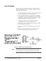
Current Output
The proper sequence of operation for outputting a current from the D/A
Converter is provided below. Refer, as necessary, to Chapters 2 and 3 for
additional operating information.
1. Determine the number of current outputs required, and configure the
necessary channel jumpers for current (refer to page 17).
2. Connect the output leads to the correct channel V/I + and - terminals
(refer to page 18). Do not connect anything to the S + and - terminals.
If extending the output range, connect the required number of channels
in parallel to obtain the desired output (refer to page 29).
3. Verify that the compliance voltage will not be exceeded by
calculating the total circuit resistance using Figure 4-6.
4. Install the D/A Converter in the Mainframe and connect the output
leads to the load (refer to Chapter 3).
5. Determine if an electronic current adjustment is necessary (refer to
page 26).
6. Enter and execute the proper instructions to output the desired
current(s), and the desired mode (refer to pages 29–30).
Figure 4-6. Output Current Compliance Voltage
Note
36
The compliance current is 24 mA. The maximum short circuit current
(e.g. R2 = 0 in Figure 4-6) is limited to ≤30 mA by the Agilent E1328A.
Understanding the Agilent E1328A
Chapter 4
Querying the D/A Converter
This section summarizes the query commands you can use to determine the
configuration or state of the D/A Converter. All commands end with the
"?" which puts the data into the output buffer where you can retrieve it.
Calibration mode state:
CALibraten:STATe?
(n = channel number)
Current output level:
SOURce:CURRentn?
(n = channel number)
Display channel selected:
DISPlay:MONitor:CHANnel?
Display present output setting: DISPlay:MONitor:STRing?
Chapter 4
System error:
SYSTem:ERRor?
V/I jumper position:
SOURce:FUNCn?
(n = channel number)
Voltage output level:
SOURce:VOLTn?
(n = channel number)
Understanding the Agilent E1328A
37
Notes
38
Understanding the Agilent E1328A
Chapter 4
Chapter 5
Agilent E1328A Command Reference
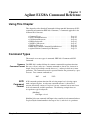
Using This Chapter
This chapter describes Standard Commands for Programmable Instruments (SCPI)
commands and summarizes IEEE 488.2 Common (*) Commands applicable to the
4-Channel D/A Converter.
•
•
•
•
•
•
•
•
Command Types . . . . . . . . . . . . . . . . . .
SCPI Command Reference . . . . . . . . . . . . .
CALibration Subsystem . . . . . . . . . . . . . . .
DISPlay Subsystem . . . . . . . . . . . . . . . . .
[SOURce:] Subsystem . . . . . . . . . . . . . . .
SYSTem Subsystem . . . . . . . . . . . . . . . .
IEEE 488.2 Common Command Quick Reference .
Agilent E1328A Command Quick Reference . . .
.
.
.
.
.
.
.
.
.
.
.
.
.
.
.
.
.
.
.
.
.
.
.
.
.
.
.
.
.
.
.
.
.
.
.
.
.
.
.
.
.
.
.
.
.
.
.
.
. Page 39
. Page 41
. Page 42
. Page 45
. Page 47
. Page 49
. Page 50
. Page 51
Command Types
This manual covers two types of commands: IEEE 488.2 Common and SCPI
Commands.
Common The IEEE 488.2 standard defines the common commands that perform functions
Command Format like reset, self-test, and so on. Common commands are four or five characters in
length, always begin with the asterisk character (*), and may include one or more
parameters. The command keyword is separated from the first parameter by a space
character. Two common commands are:
*RST
SCPI
Command
Format
and
*TST?
SCPI commands perform functions like selecting output level, selecting output
mode, and querying data. A subsystem command structure is a hierarchical
structure that usually consists of a top level (or root) command, one or more lower
level sub commands, and their parameters. The following example shows an
excerpt from a typical subsystem:
[SOURce:]
VOLTagen <level>
[SOURce:] is the root command, VOLTagen is the second-level sub command (where n
is replaced by the channel number in the range of 1 to 4), and <level> is a parameter.
Chapter 5
Agilent E1328A Command Reference
39
Command A colon (:) always separates one command from the next lower-level command as
Separator shown below:
DISPlay:MONitor[:STATe] <mode>
Abbreviated and The command syntax shows most commands as a mix of upper and lower case
Short Commands letters. The upper case letters indicate the abbreviated spelling for the command.
For shorter program lines, send only the abbreviated form. For better program
readability, you may send the entire command. The instrument accepts either the
abbreviated form or the entire command.
For example, if the command reference syntax shows the command SOURce, then
SOUR and SOURce are both acceptable forms. Other forms of SOURce, such as
SOURC, will generate an error. You may use upper case and lower case letters;
SOURCE, source, and SoUrCe are acceptable.
Implied Implied commands are those which appear in square brackets ([ ]) in the command
Commands syntax. (Note that the brackets are not part of the command and are not sent to
the instrument). Suppose you send a second-level command but do not send the
preceding implied command. In this case, the instrument assumes you intend to use
the implied command and it responds as if you had sent it. Examine an excerpt
from the [SOURce:] subsystem shown below:
[SOURce:]
VOLTagen?
The root command [SOURce:] is an implied command. To query the instrument
about a voltage level set on channel 1, send either of the following commands:
SOUR:VOLT1?
or
VOLT1?
Parameters Parameters are enclosed in greater than/less than symbols (< >) in the command
syntax. When more than one parameter is allowed, the parameters are separated by
a vertical line ( | ).
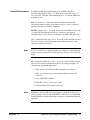
Parameter Types. The following table contains explanations and examples of
parameter types you might see later in this chapter. Parameters must always be
separated from the keywords by a space.
Parameter Type
Numeric
Explanations and Examples
Accepts all commonly used decimal representations of numbers
including optional signs, decimal points, and scientific notation.
123 or 123E2; -123 or -1.23E2; .123, 1.23E-2, or 1.23000E-01.
Special cases include MINimum, MAXimum, and DEFault.
Boolean
Represents a single binary condition that is either true or false.
1 or ON; 0 or OFF.
40
Agilent E1328A Command Reference
Chapter 5
Linking
Commands
Linking IEEE 488.2 Common Commands with SCPI Commands. Use a
semicolon (;) between the commands. For example:
*RST;VOLT1?
Linking Multiple SCPI Commands. Use both a semicolon (;) and a
colon (:) between the commands. For example:
VOLT1?;:CURR2?
SCPI Command Reference
The following sections describe the Standard Commands for Programmable
Instruments (SCPI) commands for the Agilent E1328A 4-Channel D/A Converter
Module. Commands are listed alphabetically by subsystem and within each
subsystem. A command guide is printed in the top margin of each page. The guide
indicates the current subsystem on that page.
Chapter 5
Agilent E1328A Command Reference
41
CALibration
The CALibration subsystem selects the mode of operation (calibrated or
non-calibrated) under which a specific channel will operate, and is also used to enter
updated adjustment constants during electronic adjustment procedures.
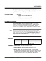
Subsystem Syntax
CALibrationn
:CURRent <measured | MIN | MAX | DEF>
:STATe <mode>
:STATe?
:VOLTage <measured | MIN | MAX | DEF>
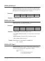
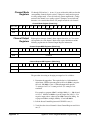
CALibrationn:CURRent
CALibrationn:CURRent <measured | MIN | MAX | DEF> is used to enter a
channel’s measurement data obtained during an electronic current adjustment.
These values are used to update the stored adjustment constants. The three
measured values are MINimum (-24mA), DEFault (0mA), and MAXimum (+24mA).
Note
During an electronic adjustment, the output current must be measured with the
channel configured in the non-calibrated mode (CALibrationn:STATe OFF). If the
output current is measured in the calibrated mode (CALibrationn:STATe ON), and
these measured values are entered using the CALibrationn:CURRent command,
output current errors will result when the channel is used in the calibrated mode.
Parameters
Parameter Name
Parameter Type
Range of Values
Default Values
CALibrationn
keyword
1, 2, 3, or 4
1
<measured>
numeric
-0.030 to -0.015
-0.005 to +0.005
+0.015 to +0.030
Amps
Comments • Channel Number: Select only one channel at a time.
• Related Commands: [SOURce:]CURRentn, CALibrationn:STATe
• Measured Values: Three values (MIN | DEF | MAX) are measured in the
non-calibrated mode, then entered to 51⁄2-digits. Once entered, the D/A Converter
calculates and stores new adjustment constants. These stored constants are used
to maintain the channel’s accuracy in the output current calibrated mode.
42
Agilent E1328A Command Reference
Chapter 5
Example Entering Channel 4 Measurement Data.
This command enters the minimum, default, and maximum measured values
channel 4 output during an electronic adjustment procedure.
CAL4:CURR -0.02359, 0.00012, +0.02405
CALibrationn:STATe
CALibrationn:STATe <mode> enables or disables the calibrated mode for a
specific channel.
Parameters
Parameter Name
Parameter Type
Range of Values
Default Values
CALibrationn
keyword
1, 2, 3, or 4
1
<mode>
boolean
0 | 1 | ON | OFF
1 | ON
Comments • Channel Number: Select only one channel at a time.
• Related Commands: CALibrationn:CURRent, CALibrationn:VOLTage,
[SOURce:]VOLTagen, [SOURce:]CURRentn
• *RST Condition: CALibration:STATe 1
Example Setting Channel 3 to Non-Calibrated Mode.
CAL3:STAT OFF
Set channel 3 mode to non-calibrated output.
CALibrationn:STATe?
CALibrationn:STATe? queries a specific channel about the currently selected
mode of operation. 1 (one) indicates operating under calibrated mode, and 0 (zero)
indicates operating under non-calibrated mode.
Chapter 5
Agilent E1328A Command Reference
43
CALibrationn:VOLTage
CALibrationn:VOLTage <measured | MIN | MAX | DEF> is used to enter a
channel’s measurement data obtained during an electronic voltage adjustment.
These values are used to update the stored adjustment constants. The three
measured values are MINimum (-12V), DEFault (0V), and MAXimum (+12V).
Note
During an electronic adjustment, the output voltage must be measured with the
channel configured in the non-calibrated mode (CALibrationn:STATe OFF). If the
output voltage is measured in the calibrated mode (CALibrationn:STATe ON), and
these measured values are entered using the CALibrationn:VOLTage command,
output voltage errors will result when the channel is used in the calibrated mode.
Parameters
Parameter Name
Parameter Type
Range of Values
Default Values
CALibrationn
keyword
1, 2, 3, or 4
1
<measured>
numeric
-15.0 to -8.0
-1.0 to +1.0
+8.0 to +15.0
Volts
Comments • Channel Number: Select only one channel at a time.
• Related Commands: CALibrationn:STATe, [SOURce:]VOLTagen
• Measured Values: Three values (MIN | DEF | MAX) are measured in the
non-calibrated mode, then entered to 51⁄2-digits. Once entered, the D/A Converter
calculates and stores new adjustment constants. These stored constants are used
to maintain the channel’s accuracy in the output voltage calibrated mode.
Example Entering Channel 2 Measurement Data.
This command enters the minimum, default, and maximum measured values
channel 2 output during an electronic adjustment procedure.
CAL2:VOLT -12.00346, 0.00352, +11.98342
44
Agilent E1328A Command Reference
Chapter 5
DISPlay
The DISPlay subsystem monitors the channel state of a selected module in a
mainframe. This command operates with mainframes that have a display, such as
the Agilent E1301B Mainframe.
Subsystem Syntax
DISPlay
:MONitor
:CHANnel <channel | MIN | MAX | DEF | AUTO>
:CHANnel? <channel>
[:STATe] <mode>
:STRing?
DISPlay:MONitor:CHANnel
DISPlay:MONitor:CHANnel <channel | MIN | MAX | DEF | AUTO> selects the
channel to be monitored when the monitor mode is enabled.
Parameters
Parameter Name
Parameter Type
Range of Values
Default Values
<channel>
numeric
1 to 4 | DEF | MIN | MAX | AUTO
1
Comments • Selecting Monitor Channel Values: When using the DISPlay:MONitor:CHANnel
command, numbers 1 to 4 select a specific channel to be monitored. In addition
to selecting a specific channel, four other values can be entered. DEFault and
MINimum selects channel 1, MAXimum selects channel 4, and AUTO activates the
automatic mode where the last channel changed is displayed.
• Monitor Mode on an Agilent 1301B Mainframe Display: Selecting the
channel causes the information to be displayed on the mainframe’s front panel.
The DISPlay:MONitor:STRing? command must be used to display the information
on the computer. The following shows the monitor mode display string on the
display of an Agilent E1301B Mainframe:
CHAN1 10.00000E01 VOLT, CAL 1
The example above shows channel 1, 10 Vdc, in the calibrated mode.
• Related Commands: DISPlay:MONitor[:STATe]
Example Selecting Channel 1 for Monitoring.
DISP:MON:CHAN 1
Chapter 5
Agilent E1328A Command Reference
45
DISPlay:MONitor:CHANnel?
DISPlay:MONitor:CHANnel? <channel> performs two different functions
dependent on if the parameter (<channel>) is used.
If <channel> is not used (blank): queries which channel will be displayed when the
monitor mode is enabled. -1 indicates operating in automatic mode (displays the last
channel changed). 1 through 4 indicates which specific channel will be displayed.
If <channel> is used (DEF | MIN | MAX): queries available channel information.
DEFault and MINimum always returns 1, and MAXimum always returns 4.
DISPlay:MONitor[:STATe]
DISPlay:MONitor[:STATe] <mode> turns the monitor mode on or off.
Parameters
Parameter Name
Parameter Type
Range of Values
Default Values
<mode>
boolean
0 | 1 | ON | OFF
0 | OFF
Comments • The [:STATe] parameter is optional. Therefore, either of the following command
statements is valid:
DISP:MON:STAT ON
or
DISP:MON ON
• Monitoring Module Channels: DISPlay:MONitor:STATe ON or
DISPlay:MONitor:STATe 1 turns the monitor mode on to show the selected
channel state. DISPlay:MONitor:STATe OFF or DISPlay:MONitor:STATe 0 turns
the monitor mode off.
• Selecting the Channel to be Monitored: Use the DISPlay:MONitor:CHANnel
command to select the channel.
• *RST Condition: DISPlay:MONitor[:STATe] OFF
Example Enabling the Monitor Mode.
This command selects monitor mode to on.
DISP:MON:STAT 1
DISPlay:MONitor:STRing?
DISPlay:MONitor:STRing? queries the channel for output information. Channel is
selected by the DISPlay:MONitor:CHANnel command, and enabled by the
DISPlay:MONitor[:STATe] command. Display string is two 25-character fields
separated by a comma.
46
Agilent E1328A Command Reference
Chapter 5
[SOURce:]
The [SOURce:] subsystem selects a channels output type (voltage or current), and level.
Subsystem Syntax
[SOURce:]
CURRentn <level>
CURRentn?
FUNCtionn?
VOLTagen <level>
VOLTagen?
[SOURce:]CURRentn
[SOURce:]CURRentn <level | MIN | MAX | DEF> configures the D/A Converter to
output current on a specified channel (n) at a specified level.
Parameters
Parameter Name
Parameter Type
Range of Values
Default Values
n
numeric
1, 2, 3, or 4
1
<level>
numeric
-0.024 to +0.024 | MIN |
MAX | DEF
0
Comments • Channel Number: Select only one channel at a time.
• If a “Settings Conflict” Error Occurs: See “Selecting Voltage or Current Output”
on page 17.
• Related Commands: CALibrationn:STATe
• *RST Condition: [SOURce:]CURRent 0
Example Setting Channel 2 to Current Output at +20 mAdc.
SOUR:CURR2 .020
[SOURce:]CURRentn?
[SOURce:]CURRentn? queries a specific channel about the currently selected
current level on the channel specified by n. If the specified channel is configured
for voltage, an error will be generated. Output format is as follows:
SDDDDDDDESDDD
Where:
S = + or D = 0 to 9 with floating decimal point
E = base 100 exponent delimiter
Chapter 5
Agilent E1328A Command Reference
47
[SOURce:]FUNCtionn?
[SOURce:]FUNCtionn? queries a specific channel about the configuration of the
specified V/I jumper in the channel’s digital section. Does not indicate V/I jumper
position of the two jumpers in the analog section. Returns CURR if the jumper is in
the "I" position or VOLT if the jumper is in the "V" position.
Parameters
Parameter Name
Parameter Type
Range of Values
Default Values
n
numeric
1, 2, 3, or 4
1
Comments • Channel Number: Select only one channel at a time.
[SOURce:]VOLTagen
[SOURce:]VOLTagen <level | MIN | MAX | DEF> configures the D/A Converter to
output voltage on a specified channel at a specified level.
Parameters
Parameter Name
Parameter Type
Range of Values
Default Values
n
numeric
1, 2, 3, or 4
1
<level>
numeric
-12 to +12 | MIN | MAX | DEF
0
Comments • Channel Number: Select only one channel at a time.
• If a “Settings Conflict” Error Occurs: See “Selecting Voltage or Current Output”
on page 17.
• Related Commands: CALibrationn:STATe, CALibrationn:VOLTage
• *RST Condition: [SOURce:]VOLTage 0
Example Setting Channel 1 to Voltage Output at +10.000000 Volts.
VOLT1 10.000000
[SOURce:]VOLTagen?
[SOURce:]VOLTagen? queries a specific channel about the currently selected
voltage level on the channel specified by n. If the specified channel is configured
for current, an error will be generated. Output format is as follows:
SDDDDDDDESDDD
Where:
S = + or D = 0 to 9 with floating decimal point
E = base 100 exponent delimiter
48
Agilent E1328A Command Reference
Chapter 5
SYSTem
The SYSTem subsystem returns the error numbers and error messages in the error
queue, and returns the types of modules (cards).
Subsystem Syntax
SYSTem
:ERRor?
SYSTem:ERRor?
SYSTem:ERRor? returns the error numbers and error messages in the error queue.
See Appendix C for a listing of the error numbers and messages.
Comments • Error Numbers/Messages in the Error Queue: Each error generated by the
D/A Converter stores an error number and corresponding error message in the
error queue. Each error message can be up to 255 characters long.
• Clearing the Error Queue: An error number/message is removed from the
queue each time the SYSTem:ERRor? command is sent. The errors are cleared
first-in, first-out. When the queue is empty, each SYSTem:ERRor? command
returns "0, No error". To clear all error numbers/messages in the queue, execute
the *CLS command (see the mainframe operating manual).
• Maximum Error Numbers/Messages in the Error Queue: The queue holds a
maximum of 30 error numbers/messages for the D/A Converter. If the queue
overflows, the last error number/message in the queue is replaced by "-350, Too
many errors". The least recent error numbers/messages remain in the queue and
the most recent are discarded.
Example Reading the Error Queue.
This command queries the error queue, reads and prints the numbers/message.
SYST:ERR?
Chapter 5
Agilent E1328A Command Reference
49
IEEE-488.2 Common Command Quick Reference
The following table lists the IEEE 488.2 Common (*) Commands that can be
executed by the D/A Converter Module. For more information on Common
Commands, refer to the Agilent E1300B/E1301B User’s Manual, the
Agilent E1406A Command Module User’s Manual, or the ANSI/IEEE Standard
488.2-1987.
Command
Title
Description
*IDN?
Identification Query
Returns Identification String of the D/A Converter.
*RST
Reset
Performs a 5-second self-test, places 0Vdc/0mAdc on all channels,
and then sets the mode of all channels calibrated (ON).
*TST?
Self-Test Query
Returns 0 unless self-test fails.
*OPC
Operation Complete
(See note below).
*OPC?
Operation Complete Query
Returns a 1 if previous operation is complete.
*WAI
Wait to Complete
(See note below).
*CLS
Clear Status Register
Clears all Status Register (see SYSTem:ERRor?).
*ESE
Event Status Enable
(See note below).
*ESE?
Event Status Enable Query
(See note below).
*ESR?
Event Status Register Query
(See note below).
*SRE
Service Request Enable
(See note below).
*SRE?
Service Request Enable
Query
(See note below).
*STB?
Read Status Byte Query
(See note below).
*RCL <n> Recall Saved State
Recalls previously stored D/A Converter Module configuration.
<n> indicates location in memory from 0 to 9.
*SAV <n> Save State
Stores the current D/A Converter Module configuration in memory.
<n> indicates location in memory from 0 to 9.
Note
50
These commands have little or no effect on D/A Converter operation. Refer to the
Agilent E1300B/E1301B Mainframe User’s Manual, the Agilent E1406A Command
Module User’s Manual, or the ANSI/IEEE Standard 488.2-1987 for more
information.
Agilent E1328A Command Reference
Chapter 5
Agilent E1328A Command Quick Reference
The following table summarizes SCPI Commands for the Agilent E1328A.
SCPI Commands Quick Reference
Command
Subsystem
CALibrationn
DISPlay
Command/Parameter
Description
:CURRent <measured>
Enters three measured values to update the
channel’s stored current adjustment constant.
:STATe <mode>
Selects mode to calibrated (1) or non-calibrated (0).
:STATe?
Returns mode channel is currently operating under.
:VOLTage <measured>
Enters three measured values to update the
channel’s stored voltage adjustment constant.
:MONitor:CHANnel <channel> Enters the desired channel number to be viewed
when in monitor mode (1 to 4 or auto).
:MONitor:CHANnel? <channel> Returns the presently selected channel number to be
viewed when in monitor mode (1 to 4 or auto); or the
DEFault, MINimum, or MAXimum available channel
number.
[SOURce:]
SYSTem
Chapter 5
:MONitor[:STATe] <mode>
Selects monitor mode to on (1) or off (0).
:MONitor:STRing?
Returns the selected channel number (1 to 4),
output configuration (voltage or current), output
level, and mode (calibrated or non-calibrated).
:CURRentn <level>
Sets the specified channel (n) to output the specific
current level.
:CURRentn?
Returns the current level the specified channel (n)
is currently set to output.
:FUNCtionn?
Returns the present position of the V/I jumper in
the specified channel’s (n) digital section.
:VOLTagen <level>
Sets the specified channel (n) to output the specific
voltage level.
:VOLTagen?
Returns the voltage level the specified channel (n)
is currently set to output.
:ERRor?
Returns the error number/message in the error queue.
Agilent E1328A Command Reference
51
Notes
52
Agilent E1328A Command Reference
Chapter 5
Appendix A
Agilent E1328A Specifications
DC Voltage
Range:
± 10.92 V (cal on)
± 12 V (cal off)
DC Current
Range:
± 21.8 mA (cal on)
± 24.0 mA (cal off)
Resolution:
333 µV programming interval (cal on)
16-bit resolution (cal off)
Monotonic to 2 mV at 25°C
Resolution:
667 nA programming interval (cal on)
16-bit resolution (cal off)
Monotonic to 4 µA at 25°C
Accuracy: ± (% of output + volts)
Conditions: cal on, within ± 5°C of
cal temperature and same load as at calibration.
24-hour:
± (0.05% of output + 3.3 mV)*
90-day:
± (0.15% of output + 29 mV)
1 year:
± (0.30% of output + 110 mV)
Accuracy: ± (% of output + amps)
Conditions: Cal on, within ± 5°C of cal temperature
and same load as at calibration.
24-hour:
± (0.05% of output + 7 µA)
90-day:
± (0.15% of output + 59 µA
1 year:
± (0.3% of output + 220 µA)
Temperature Coefficient: ± (.01% + 0.667 mV)/°C Temperature Coefficient: ± (0.01% + 1.33 µA)/°C
*(For loads ≥ 500 Ω, the maximum additional
Output Voltage:
error due to using a load different than that
Compliance voltage: 13 V
used for calibration is ± 0.02% of output.)
Max open circuit voltage: ≤ 19V
Typical output impedance: > 25 MΩ
Output Current:
Compliance current: 24 mA
Short circuit current: ≤ 30mA
Differential Ripple and Noise:
< 2 mVrms in Agilent 75000 mainframe
(20 Hz – 250 kHz, 1 kΩ load)
Differential Ripple and Noise:
< 4 µArms in Agilent 75000 mainframe
(20 Hz – 250 kHz, into 100 Ω)
Common Mode Noise
(V/I to chassis, 1 kΩ):
<30 mV in Agilent 75000 Mainframe
Appendix A
Agilent E1328A Specifications
53
General
Settling Time:
Conditions: single channel, to rated accuracy
750 µs (cal on), 500 µs (cal off)
Isolation:
250 Vrms, 350 Vdc/ac peak
(channel-to-channel or chassis)
15 Vdc/ac, peak (channel-to-sense)
Power Requirements:
+ 5 + 12
Voltage:
Peak module
current, IPM (A): 0.40 0.50
Dynamic module
current, IDM (A): 0.02 0.01
Watts/Slot: 6.5
Cooling/Slot:
0.11 mm H2O @ 0.52 liter/sec.
Max wire size: 16AWG
Humidity: 65%, 0 to 40°C
Module Size/Device Type: B, register-based
Connectors Used: P1
No. Slots: 1
Operating Temperature: 0 to 55°C
Storage Temperature: -40 to 75°C
VXIbus Interface Capability: Slave, A16, D16
EMC, RFI, Safety:
meets FTZ 1046/1984, CSA 556B,
IEC 348, UL 1244
Interrupt Level: None
Net Weight (kg): 0.7
54
Agilent E1328A Specifications
Appendix A
Appendix B
Agilent E1328A Register-Based Programming
Using This Appendix
The contents of this appendix are:
•
•
•
•
•
Addressing the Registers . . . . . . . . . . . . . . . . . . . . . . . . . . . .
Register Definitions . . . . . . . . . . . . . . . . . . . . . . . . . . . . . . . .
Register Descriptions . . . . . . . . . . . . . . . . . . . . . . . . . . . . . . .
A Register-Based Algorithm . . . . . . . . . . . . . . . . . . . . . . . . .
Programming Examples. . . . . . . . . . . . . . . . . . . . . . . . . . . . .
Page 55
Page 59
Page 60
Page 71
Page 72
Addressing the Registers
To access a specific register for either read or write operations, the address of
the register must be used. Register addresses for the plug-in modules are found
in an address space known as VXI A16. The exact location of A16 within a
VXIbus master’s memory map depends on the design of the VXIbus master
you are using; for the Agilent E1300/1301 Mainframe and
Agilent E1405/E1406 Command Module, the A16 space location starts at
1F0000161.
The A16 space is further divided so that the modules are addressed only at
locations above 1FC00016 within A16. Further, every module is allocated 64
register addresses (4016). The address of a module is determined by its logical
address (set by the address switch on the module) times 64 (4016). In the case
of the D/A Converter module, the factory default address setting is 72 or 4816.
Register addresses for register-based devices are located in the upper 25%
of VXI A16 address space. Every VXI device (up to 256) is allocated a
64-byte block of addresses.
Figure B-1 shows the register address location within A16. Figure B-2 shows
the location of A16 address space in the Agilent E1405/E1406 Command
Module.
1 The "16" at the end of the address indicates a hexadecimal base number.
Appendix B
Agilent E1328A Register-Based Programming
55
The Base Address
A16 Address Space
Outside the Command
Module (on the VXIbus)
When you are reading or writing to a module register, a hexadecimal or
decimal register address is specified. This address consists of a base
address plus a register offset. The base address used in register-based
programming depends on whether the A16 address space is outside or inside
the Agilent E1405/06 Command Module.
When the Agilent E1405/06 Command Module is not part of your VXIbus
system (Figure B-1), the Agilent E1328’s base address is computed as:
C00016 + (LADDR * 64)16
or (decimal)
49,152 + (LADDR * 64)
where C00016 (49,152) is the starting location of the register addresses,
LADDR is the module’s logical address, and 64 is the number of address
bytes per VXI device. For example, the Agilent E1328’s factory set logical
address is 72 (4816), therefore it will have a base address of:
C00016 + (72 * 64)16 = C00016 + 120016 = D20016
or (decimal)
49,152 + (72 * 64) = 49,152 + 4,608 = 53,760
Figure B-1. Register Address Location within A16 Address Space
56
Agilent E1328A Register-Based Programming
Appendix B
A16 Address Space
Inside the
Agilent E1405/06
Command Module or
Agilent E1300/01
Mainframe
When the A16 address space is inside the Agilent E1405/E1406 Command
Module (Figure B-2, the module’s base address is computed as:
1FC00016 + (LADDR * 64)16
or
2,080,768 + (LADDR * 64)
where 1FC00016 (2,080,768) is the starting location of the VXI A16
addresses, LADDR is the module’s logical address, and 64 is the number of
address bytes per register-based device. Again, the Agilent E1328’s factory
set logical address is 72. If this address is not changed, the module will
have a base address of:
1FC00016 + (72 * 64)16 = 1FC00016 + 120016 = 1FD20016
or
2,080,768 + (72 * 64) = 2,080,768 + 4608 = 2,085,376
Figure B-2. Address Space in the Mainframe and Command Module
Appendix B
Agilent E1328A Register-Based Programming
57
Register Offset
The register offset is the register’s location in the block of 64 address bytes
that belong to the module. For example, the module’s Status/Control
Register has an offset of 0416. When you write a command to this register,
the offset is added to the base address to form the register address:
D20016 + 0416 = D20416 1FD20016 + 0416 = 1FD20416
or
53,760 + 4 = 53,764
2,085,376 + 4 = 2,085,380
Table B-1 shows the general programming method for accessing the
Agilent E1328A registers using different computers.
Table B-1. Accessing the Agilent E1328A Registers
Computer
Programming Method
Base Address
E1300/01 IBASIC
(Absolute Addressing)
READIO (-9826, Base_addr + offset)
WRITEIO -9826, Base_addr + offset; data
(positive select code = byte read or write
negative select code = word read or write)
Base_addr = 1FC00016 + (LADDR * 64)16
or
= 2,080,768 + (LADDR * 64)
offset = register offset (Figure B-2)
(select code 8)
External Computer
(over GPIB to
Agilent E1300/E1301
Mainframe or
Agilent E1405/E1406
Command Module)
V/382 Embedded
Computer
(C-Size system)
Agilent RADI-EPC7
Embedded Computer
with SICL
READIO (8, Base_addr + reg number)
WRITEIO 8, Base_addr + reg number; data
Base_addr = LADDR * 256
reg number = register offset (Figure B-2)/2
VXI:READ? logical_address, offset
VXI:WRITE logical_address, offset, data
Module logical address setting (LADDR)
offset = register offset (Figure B-2)
DIAG:PEEK? Base_addr + offset, width
DIAG:POKE Base_addr + offset, width, data
Base_addr = 1FC00016 + (LADDR * 64)16
or
= 2,080,768 + (LADDR * 64)
offset = register offset (Figure B-2)
READIO (-16, Base_addr + offset)
WRITEIO -16, Base_addr + offset; data
Base_addr = C00016 + (LADDR * 64)16
or
= 49,152 + (LADDR * 64)
(positive select code = byte read or write
negative select code = word read or write)
offset = register offset (Figure B-1)
iwpeek((unsigned short *)
(base_addr + offset))
INST device_name;
device_name = iopen
(“vxi, logical address”);
base_addr = imap
(device_name, I_MAP_VXIDEV,0,1,NULL);
iwpoke((unsigned short *)
(base_addr + offset),data)
LADDR: Agilent E1328A logical address = 72
(LADDR * 64)16: Multiply quantity then convert to a hexadecimal number (e.g. (72 * 64)16 = 120016)
When using DIAG:PEEK? and DIAG:POKE, the width (number of bits) is either 8 or 16.
58
Agilent E1328A Register-Based Programming
Appendix B
Register Definitions
Table B-2 lists the registers on the Agilent E1328A 4-Channel D/A
Converter Module and whether you can read or write to the registers.
Table B-2. Register Map
Register
Offset
Appendix B
Definition
High Byte
Low Byte
1E16
Channel 4 LSB Output (write only)
ignored
Channel 4 Least
Significant Byte (LSB)
1C16
Channel 4 MSB Output (write only)
ignored
Channel 4 Most
Significant Byte (MSB)
1A16
Channel 3 LSB Output (write only)
ignored
Channel 3 LSB
1816
Channel 3 MSB Output (write only)
ignored
Channel 3 MSB
1616
Channel 2 LSB Output (write only)
ignored
Channel 2 LSB
1416
Channel 2 MSB Output (write only)
ignored
Channel 2 MSB
1216
Channel 1 LSB Output (write only)
ignored
Channel 1 LSB
1016
Channel 1 MSB Output (write only)
ignored
Channel 1 MSB
0E16
reserved
reserved
0C16
reserved
reserved
0A16
Parameter Register
(read or write to lower byte)
ignored
Parameter Register
0816
Command Register
(read or write to lower byte)
ignored
Command Register
0616
Channel Mode Register (read only)
0416
Status/Control Register
(read or write to lower byte)
Status/Control Register
Status/Control Register
0216
Device Type Register (read only)
Device Type Register
Device Type Register
0016
Manufacture ID Register (read only)
ID Register
ID Register
FF16
Channel Mode Register
Agilent E1328A Register-Based Programming
59
Register Descriptions
The following pages detail register descriptions for the Agilent E1328A
4-Channel D/A Converter Module.
Manufacturer ID
Register
Reading this register returns FFFF16. This shows Agilent Technologies as
the manufacturer and that the module is an A16 register based device.
Manufacturer ID Register (Read Only)
Base + 0016
15
14
13
12
11
10
9
8
7
6
Write
Undefined
Read*
Manufacturer ID
5
4
3
2
1
0
*Returns FFFF16 = Agilent Technologies A16 only register-based.
Device Type
Register
Reading this register returns FF7F16. This shows that the device is an
Agilent E1328A 4-Channel D/A Converter Module.
Device Type Register (Read Only)
Base + 0216
15
14
13
12
11
10
9
8
Write
Read
7
6
5
4
3
2
1
0
1
1
1
1
1
1
1
Undefined
1
1
1
1
Status/Control
Register
1
1
1
1
0
Eleven 1-bit fields provide information on equipment and operational status.
Refer to the register definitions and the following explanation for
Status/Control Register information.
Status/Control Register (Read/Write)
Base + 0416
15
14
13
12
11
10
9
8
7
6
5
4
3
2
1
0
Write
-
-
-
-
-
-
-
-
-
-
-
-
-
-
SFI
SR
Read
1
1
1
1
S4
S3
S2
1
C/P RDY
S1 DON ER*
IE*
CF* READY PAS
C/P RDY: (Ready - bit 0). A one (1) in this field indicates that the D/A
Converter’s data buffer is empty and that data may be written to registers
0816 through 1E16. Note: This bit was formerly called RDY.
Note
60
This bit must be checked before writing to registers 0816 through 1E16
(except the RESTART command).
Agilent E1328A Register-Based Programming
Appendix B
Status Bit Precedence
In addition to bit 0 indicating the DAC ready condition, bit 0 also
determines the validity of bits 6 - 11. When bit 0 is cleared (0), bits 6 - 11
may be invalid. Therefore, when monitoring bits 6 - 11, that bit AND bit 0
must both be true.
PAS: (Passed - bit 2). A zero (0) in this field indicates that the D/A
Converter is either executing, or has failed a self test. A one (1) indicates
that the self test has successfully completed.
READY: (Ready - bit 3). A zero (0) in this field in combination with a one
(1) in the PAS field indicates that the D/A Converter is executing an
extended self test. Note: This bit was formerly called EX* (Extended (not)).
CF*: (Checksum-failure (not) - bit 4). A zero (0) in this field indicates that
the D/A Converter’s stored adjustment constants did not have the correct
checksum, and may be incorrect.
Note
If CF* is asserted, it is recommended that each channel be calibrated in both
voltage and current modes before using the D/A Converter in the calibrated
mode.
IE*: (Internal-exception (not) - bit 5). A zero (0) in this field indicates that
the D/A Converter has encountered an error in executing its program. To
clear the error, perform the steps below.
1. Write correct CAL-ON/CAL-OFF commands to each channel.
2. Write correct output data to each channel (ignore the state of the
settle bits).
3. Issue a RESTART command.
4. When IE* is one (1), repeat steps 1 and 2.
5. If this procedure fails, perform a soft reset.
Note
Appendix B
Performing a soft reset (SR) will zero all outputs, cause the D/A Converter to
execute a self-test, and assert the SYSFAIL line. Therefore, it is recommended
that the SFI bit be set before performing a soft reset to avoid halting mainframe
operations.
Agilent E1328A Register-Based Programming
61
ER*: (Error (not) - bit 6). A zero (0) in this field indicates that an error has
occurred in executing a command. The error condition is cleared on receipt
of another command. The recommended way of clearing the error
condition is by sending the NULL command. Channel output operations
have no effect on this bit.
DON: (Done - bit 7). A one (1) this field indicates that the previous
command has been completed. Writing to the Command Register (0816)
when this bit is zero (0) may abort the command in progress. Channel
output operations have no effect on this bit.
S1 through S4: (Settle Flags - bits 8 to 11). A one (1) in one of these
fields indicates that the corresponding channel output is stable. A zero (0)
indicates that the channel output is or will be changing. Writing to a
channel when its settle flag is low (0) could corrupt the output data.
SR: (Soft Reset - bit 0). Writing a one (1) causes the D/A Converter to
enter a reset state. Channel output data will be lost and all pending
commands will be terminated. Registers 0816 through 1E16 cannot be
accessed when Soft Reset is set. The D/A Converter will be held in the
reset condition until a zero (0) is written to the SR bit, at which time the
power-on self test and start-up sequence will be executed. It is
recommended that the SR bit remain high for >200 msec.
CAUTION
Only perform a soft reset if the "RESTART" command fails (see “Command
and Parameter Registers” later in this appendix). This is because when the
D/A Converter is soft reset, power is removed from the output channels, and
the output state during power-down is indeterminate.
SFI: (SysFail Inhibit - bit 1). Writing a one (1) inhibits the assertion of the
SYSFAIL line on the backplane.
62
Agilent E1328A Register-Based Programming
Appendix B
Channel Mode
Registers
V1 through V4 (bits 0 to 3). A one (1) in any of these bits indicates that the
corresponding channels digital section V/I jumper is configured to operate
in voltage output mode. A zero (0) indicates current output mode. Configuration of the channel’s two analog section V/I jumpers are not indicated;
therefore, it is essential that all three V/I jumpers match for each channel.
Channel Mode Register (Read Only)
Base + 0616
15
14
13
12
11
10
9
Write
Read
8
7
6
5
4
3
2
1
0
1
1
1
V4
V3
V2
V1
Undefined
1
1
1
Channel Output
Registers
1
1
1
1
1
1
Eight registers (two per channel) allow output value to be set. Two writes
are required to set each channel. Refer to the register definitions and the
following explanation for Channel Output Register information.
Channel Output MSB Registers (Write Only)
Base + *
15
14
13
Write
12
11
10
9
8
7
6
5
Ignored
4
3
2
1
0
1
0
MSB value
Read
Undefined
*base + 1016 for channel 1, base + 1416 for channel 2, base + 1816 for channel 3, or base + 1C16 for channel 4.
Channel Output LSB Registers (Write Only)
Base + *
Write
Read
15
14
13
12
11
10
9
8
7
Ignored
6
5
4
3
2
LSB value
Undefined
*base + 1216 for channel 1, base + 1616 for channel 2, base + 1A16 for channel 3, or base + 1E16 for channel 4.
The procedure for setting or changing an output level is as follows:
1. Determine the output data. The required value is a 16-bit number in
offset binary. FFFF16 represents positive full scale, 000016 is negative
full scale, and 800016 is zero. Calibrated output modes provide
"3 counts per 1 mV" or "3 counts per 2µA" (1.5 counts per 1µA)
resolution.
For example, to program 100mV, multiply 100 by 3 ( = 300 decimal,
or 12C16). Add this to 800016 to get the output data (812C16). For
negative output values, subtract from 800016 instead of adding. Or,
to program 2500µA, multiply 2500 by 1.5 and add 800016.
2. Poll the Status/Control Register until C/P RDY is one (1).
3. Verify that the selected channel’s Status/Control Register settle bit is
one (1).
Appendix B
Agilent E1328A Register-Based Programming
63
4. Write the selected channel’s Most Significant Byte (MSB) in bits 0-7
(register 1016, 1416, 1816, or 1C16).
5. Poll the Status/Control Register until C/P RDY is one (1).
6. Write the selected channel’s Least Significant Byte (LSB) in bits 0-7
(register 1216, 1616, 1A16, or 1E16). Writing to an LSB Register will
cause the corresponding channel to be updated.
Note
The output is not changed until the LSB is received. If the MSB has not
changed from the previous entry, you need only send the LSB.
For example, to program +100 mVdc on channel 4:
1. Multiply 100 by 3 ( = 300 decimal, or 12C16). Add this to 800016 to
get the output data (= 33068 decimal, 100 0001 0010 1100 binary,
or 812C16).
2. Enter MSB (1000 0001 binary, 8116) in channel 4 MSB Register
1C16 low byte.
3. Enter LSB (0010 1100 binary, 2C16) in channel 4 LSB Register
1E16 low byte.
Command and
Parameter Registers
Seven commands control equipment operation using the 0816 register.
Three of these commands have parameters used to enter data in the 0A16
register. Refer to the register definitions and the following explanation for
Command and Parameter Register information.
Command Register (Write)
Base + 0816
15
14
13
Write
12
11
10
9
8
Ignored
7
6
5
4
3
2
1
0
Null, Cal-on/off, Calibrate, Checksum, Zero-all,
Restart
Read
Undefined
Parameter Register (Write)
Base + 0A16
Write
Read
64
15
14
13
12
11
10
9
8
7
Ignored
6
5
4
3
2
1
0
Calibrate, Checksum, and Restart
Undefined
Agilent E1328A Register-Based Programming
Appendix B
The procedure for sending a command is as follows:
1. Poll the Status/Control Register until both DON and RDY are asserted (1).
2. Write the Command byte to the Command Register (0816). If the
command is invalid (and DONE is true again), ER* will be zero (0).
The command will not be executed until all required parameters
(if any) have been received. If the command is CALIBRATE,
CHECKSUM or RESTART, enter parameters as follows:
3. Poll the Status/Control Register until C/P RDY is asserted (1).
4. Write a Parameter byte to the Parameter Register (0A16).
5. Repeat steps 3 and 4 as required to send all parameters.
Note
The D/A Converter channel number physical markings and SCPI
commands are numbered from 1 to 4, but for register-based programming
the channels are numbered 0 to 3, respectively.
Commands referencing higher channel numbers than 3 will be ignored, and the
ER* bit will be set to one (1) after receipt of the final parameter. In the
command formats given, xxx = don’t care, cccc= channel number from 0 to 3,
b = binary, and 16 = hex.
NULL: Resets the ER* bit of the Status/Control Register and terminates
any pending command. The NULL command does not have a parameter.
Command format is as follows:
0000xxxxb or 0x16.
CAL-OFF: Disables gain and offset adjustment for the indicated channel,
providing greater speed and output range, but less accuracy. The CAL-OFF
command does not have a parameter. Command format is as follows:
0010ccccb or 2c16
For example, the command 00100000b or 2016 sets channel 1 mode to
non-calibrated (CAL-OFF).
Appendix B
Agilent E1328A Register-Based Programming
65
CAL-ON: Enables gain and offset adjustment for the indicated channel,
providing greater accuracy, but less speed and output range. The CAL-ON
command does not have a parameter. Command format is as follows:
0011ccccb or 3c16
For example, the command 00110001b or 3116 sets channel 2 mode to
calibrated (CAL-ON).
CHECKSUM: Checksums the stored adjustment constants for the
specified channel, and sets the ER* bit accordingly. ER* is asserted (low) if
checksum is bad, and deasserted (high) if good. The CHECKSUM
parameter bit (m) is 0 to check current mode constants, and 1 to check
voltage mode constants. The state of the D/A Converter module’s V/I
jumpers is ignored. Command format (register 0816) is as follows:
0101ccccb or 5c16
Parameter format (register 0A16) is as follows (m is parameter):
0000000mb or 0m16
For example, the Command 01010010b or 5216 (0816 Register) and
Parameter 00000001b or 0116 (0A16 Register) performs a checksum on the
adjustment constant for channel 3 voltage.
ZERO-ALL: Writes (uncalibrated) zero to all channels as quickly as
possible. The ZERO-ALL command does not have a parameter. Command
format is as follows:
10101010b or AA16
RESTART: This command is used to recover from AC FAIL and IE*
conditions. Command format is as follows:
11110000b or F016
Parameter format is as follows (fixed parameter):
11110111b or F716
CALIBRATE: Used to change a channel’s stored voltage and/or current
adjustment constant. The state of the channel’s V/I jumpers determines
which constant is entered. These constants are used by the D/A Converter
to maintain the required output accuracy when in the calibrated mode.
The CALIBRATE command and parameter are used to enter new offset,
gain, and checksum values. These values are calculated from actual channel
output measurements, then entered into the Parameter Register.
66
Agilent E1328A Register-Based Programming
Appendix B
Command format (register 0816) is as follows:
0100ccccb or 4c16
Parameter format (register 0A16) consists of seven bytes as follows:
– Offset high byte
– Offset low byte
– Gain high byte
– Gain second byte
– Gain third byte
– Gain low byte
– Checksum byte
The procedure to perform an electronic adjustment on a channel is as follows:
1. Configure the selected channel’s V/I jumpers to voltage or current as
required (refer to page 17).
2. Connect the load and a precision multimeter to the selected channel’s
V/I output terminals. Configure the multimeter for voltage or current
as required.
3. Change the selected channel mode to CAL-OFF.
4. Output the value 000016 (minimum) and measure the resulting
voltage or current. Record the measured value as ym.
5. Output the value 800016 (default or reset) and measure the resulting
voltage or current. Record the measured value as yo.
6. Output the value FFFF16 (maximum) and measure the resulting
voltage or current. Record the measured value as yp.
7. Calculate the offset (J) and gain (K) constants using the equations
given below. The equations must be calculated using double
precision floating point arithmetic. (A sample program (in C) to
compute the J, K, and checksum (steps 7 to 8) is listed below.) If the
sample program is used, proceed to step 9.
Calculate bo and b1 as follows:
ad − eq
ep − ac
bo =
and b1 =
dp − cq
dp − cq
Appendix B
Agilent E1328A Register-Based Programming
67
where:
w = 3.65
ym = measured value in step 4
yo = measured value in step 5
yp = measured value in step 6
a= (ym) + (w)(yo) + (216 - 1)(yp)
p= w+2
c=q= (215)(w) + 216 - 1
d= (230)(w) + 232 - 217 + 1
Calculate J and K as follows:
R
ù
k = 232 éê1 − 15
ú
(2 −1)(b1) û
ë
J=
−bo
k
+ 17 − 215
b1
2
where: R= 10.92233 for volts
0.02184467 for current
K should be rounded to a 32 bit unsigned integer. Use the rounded
value of K to compute J. Round J to the nearest integer and express
in 8-bit two’s complement form.
NOTE: For maximum speed, precompute the actual output data
using the following equation, and operate the Agilent E1328A in
uncalibrated mode:
ìk × x ü
y = J + x − í 32 ý
î2 þ
where: x = desired output code (calculated as shown under “ Channel
Output Registers” on page 63) and y = value actually sent to the
Agilent E1328A.
8. Compute a checksum by adding the 6 bytes representing J and K (on
an 8-bit wide basis) and taking the two’s complement of the result.
(Checksum is defined to be that number which causes all seven bytes
to sum to zero in byte-wide arithmetic.)
For example (in hex), if offset (J) is 0B 7C and gain (K) is 16 F8 F2
1A (as calculated in step 6), then checksum would be 5F.
9. Use the CALIBRATE command and parameter to load J, K and the
checksum into the D/A Converter’s memory.
For example (using hex example values in step 8), entering the
following calculated offset (J), gain (K), and checksum for channel 4
68
Agilent E1328A Register-Based Programming
Appendix B
is as follows:
00110011b or 3316 (register 0816)
instructs channel 4 to accept the following data entries.
The seven parameters (register 0A16) are entered as follows:
0B16 is high 8 bits of calculated offset (J).
7C16 is low 8 bits of calculated offset (J).
1616 is high 8 bits of calculated gain (K).
F816 is second 8 bits of calculated gain (K).
F216 is third 8 bits of calculated gain (K).
1A16 is low 8 bits of calculated gain (K).
5F16 is calculated check sum.
10. Change the selected channel mode to CAL-ON.
11. If desired, check that the constants have been loaded correctly by
outputting 800016 and verifying that the channel output is zero 24
hour accuracy for voltage or current (see Appendix A).
Sample Program
The following is a sample program written in C to calculate J, K, and
checksum. “ ym, yo, and yp” (from steps 4-6 on page 67) are measured and
entered. Note, the program does not prompt for the value of w, the default
value of 3.65 is used.
/* This program demonstrates a weighted least-squares approach to determining DAC calibration
constants.
ym = (uncalibrated) negative full-scale output value
yp = positive full-scale output
y0 = uncalibrated zero
w = weighting factor for relative importance of zero
w = 3.65 is the recommended weighting factor
w = 1 yields conventional least-squares algorithm
The DAC characteristic is modeled as y = b1*x + b0.
The coefficients b1 and b0 are used to calculate the actual calibration constants, J and K. */
dac_line(yp, y0, ym, w, b1, b0)
double yp, y0, ym, w, *b1, *b0;
{
double u[2], M[2][2], N[2][2], d;
u[0] = ym + w * y0 + yp;
u[1] = w * 0x8000 * y0 + 0xFFFF * yp;
M[0][0] = w + 2;
M[0][1] = 0x8000 * w + 0xFFFF;
M[1][0] = M[0][1];
M[1][1] = w * (double)(0x8000) * 0x8000 + (double)(0xFFFF) * 0xFFFF;
d = M[0][0]*M[1][1] - M[0][1]*M[1][0];
N[0][0] = M[1][1] / d;
N[0][1] = - M[0][1] / d;
Appendix B
Agilent E1328A Register-Based Programming
69
N[1][0] = - M[1][0] / d;
N[1][1] = M[0][0] / d;
*b0 = N[0][0]*u[0] + N[0][1]*u[1];
*b1 = N[1][0]*u[0] + N[1][1]*u[1];
return;
}
main()
int i, Jint;
double yp, y0, ym, b1, b0, w, J, K, Rx;
unsigned long Kint, checksum;
char string[81];
w=3.65;
/* may be changed if desired */
printf(“\nEnter yp, y0, ym (in Volts or Amps)\n”);
/* prompt for data */
gets(string);
sscanf(string,"%lf, %lf, %lf",&yp,&y0,&ym);
dac_line(yp,y0,ym,w,&b1,&b0);
/* find best fit line */
printf(“\nCoefficients of best-fit line, using w = %g:\n”,w);
printf(“\tb1 = %g\n”,b1);
printf(“\tb0 = %g\n”,b0);
/* compute cal constants from best fit line */
if(yp=1) Rx = 10.92233;
/* voltage case */
else Rx = .02184467;
/* current case */
K = 1.0 - ( Rx /( 0x7fff * b1));
K *= 4.0 * 0x8000 * 0x8000;
/* mult by 2^32 */
Kint = K + .5;
/* round to integer */
J = -b0/b1 - 0x8000;
J += ((double)Kint)/(4.0*(double)0x8000);
/* divisor is 2^17 */
if(J=(double)0.0) Jint = J +.5;
/* round to integer */
else
Jint = J -.5;
/* J is negative */
/* compute an eight bit checksum */
checksum = Jint & 0xff;
checksum += Jint>8 & 0xff;
for(i=0;i<=3;i++) checksum += ( Kint>(i*8) ) & 0xff;
checksum ^= -1; checksum += 1;
/* two’s complement */
checksum &= 0xff;
/* truncate to eight bits */
printf(“\nCalibration constants are as follows for Rx = %g:\n”,Rx);
printf(“\tJ = %04x h\n”,Jint); printf(“\tK = %8lx h\n”,Kint);
printf(“\tchecksum = %02lx h\n”,checksum);
}
70
Agilent E1328A Register-Based Programming
Appendix B
A Register-Based Algorithm
The following algorithm describes the procedure you would use to program
the registers on the Agilent E1328A D/A Converter module to output either
a voltage or a current.
Figure B-3. Register-Based Programming Algorithm
Appendix B
Agilent E1328A Register-Based Programming
71
Programming Examples
The examples in this section demonstrate how to program the module at the
register level. The programs follow the algorithm described in a previous
section. The examples include:
– Resetting the Module
– Reading the ID, Device Type, and Status Registers
– Outputting a Voltage or Current
System
Configuration
The following example programs were developed with the module at logical
address 72.
– The BASIC programs were developed using the Agilent E1300
mainframe Series B IBASIC language.
– The C language programs were developed on an HP Vectra PC
(IBM PC compatible) using Borland’s Turbo C++® programming
language, the Agilent 82335 GPIB Interface and GPIB Command
Library. The last C language programming example was developed
on the Agilent RADI-EPC7 Embedded Controller.
Resetting the
Module
The following program resets the Agilent E1328A D/A Converter module.
The process is as follows:
1. Write a "2" to the Status/Control Register to set SFI high.
2. Write a "3" to the Status/Control Register to keep the SFI bit high
and set the reset bit.
3. Wait 200 mS.
4. Write a "2" to the Status/Control Register to keep the SFI bit high
and zero the reset bit.
5. Wait 100 mS.
6. Write a "0" to the Status/Control Register.
IBASIC Version
10
Base_addr = DVAL("1FD200",16)
!Logical Address 72.
20
Reg_addr = 04 ! Offset for Status Control Register.
30
! Write a 2 then a 3 to the Status Register.
40
WRITEIO -9826, Base_addr + Reg_addr; 2
50
WRITEIO -9826, Base_addr + Reg_addr; 3
60
WAIT .2 ! wait 200 mS.
70
WRITEIO -9826, Base_addr + Reg_addr; 2
80
WAIT .1 ! wait 100 mS.
90
WRITEIO -9826, Base_addr + Reg_addr; 0
100 END
72
Agilent E1328A Register-Based Programming
Appendix B
C Version
/* reset the module */
#include <stdio.h>
#include <chpib.h>
#include <dos.h>
#define LOG_ADDR 72
/* Agilent E1328A Logical
Address */
#define BASE_ADDR (long) ((0x1FC000) + (64 * LOG_ADDR))
/* function to send values to the Status Register */
void send_value (int base_address, int data_value)
{
float
send_data[3], read;
char
state[2] = {13,10};
send_data[0] = base_address + 4;
/* Status Register offset */
send_data[1] = 16;
/* base 16 */
send_data[2] = data_value;
/* data value sent to the register */
IOEOI (7L, 0); IOEOL (7L, “ ”, 0);
/* GPIB library call */
IOOUTPUTS (70900L, “DIAG:POKE ”, 10);/* GPIB library call */
IOEOI (7L, 1); IOEOL (7L, state,0);
/* GPIB library call */
IOOUTPUTA (70900L, send_data, 3);
/* GPIB library call */
}
main ()
{
send_value(BASE_ADDR, 2);
send_value(BASE_ADDR, 3);
delay (200);
send_value(BASE_ADDR, 2);
delay (100);
/* wait 200 mS (delay is unique
to Borland Turbo C++) */
/* wait 100 mS */
send_value(BASE_ADDR, 0);
return 0;
}
Appendix B
Agilent E1328A Register-Based Programming
73
Reading the ID,
Device Type, and
Status Registers
IBASIC Version
The following examples read the ID, Device Type, and Status/Control
Registers.
10
20
30
!**********************************************************
!*****
READREG
*****
!**********************************************************
40
! OPTION BASE 0 is default.
50
! Set up arrays to store register names and addresses.
60
DIM Reg_name$(0:2)[32], Reg_addr(0:2)
70
!
80
! Read register names and addresses into the arrays.
90
READ Reg_name$(*)
100 READ Reg_addr(*)
110 !
120 ! Set base Address variable.
130 Base_addr = DVAL ("1FD200",16)
140 !
150 ! Map the A16 address space.
160 !
170 ! CONTROL 16,25;2 ! used only with V360 Controller.
180 ! Call the subprogram Read_regs.
190 Read_regs(Base_addr, Reg_name$(*),Reg_addr(*))
200 !
210 DATA Identification Register, Device Register, Status Register
220 DATA 00, 02, 04
230 END
240 ! This subprogram reads each register and prints its contents.
250 SUB Read_regs(Base_addr, Reg_name$(*),Reg_addr(*))
260 FOR Number = 0 to 2
270 Register = READIO(-9826,Base_addr + Reg_addr(number))
280 PRINT Reg_name$(number);" = "; IVAL$(Register, 16)
290 NEXT Number
300 SUBEND
This program returns:
ID Register = FFFF
Device Type Register = FF7F
Status/Control Register = (dependent on current status, default is FFFF)
74
Agilent E1328A Register-Based Programming
Appendix B
C Version
#include <stdio.h>
#include <chpib.h>
#include <cfunc.h>
#define LOG_ADDR 72
#define BASE_ADDR (long) ((0x1FC000) + (64 * LOG_ADDR))
main()
{
int reg_addr;
float send_data[3], read;
char state[2] = {13,10};
send_data[1] = 16;
send_data[2] = 0;
/* Read ID Register */
send_data[0] = BASE_ADDR + 0;
IOEOI (7L, 0); IOEOL (7L, , 0);
/* GPIB library call */
IOOUTPUTS (70900L, “DIAG:PEEK? ”, 11);/* GPIB library call */
IOEOI (7L, 1); IOEOL (7L, state, 2);
/* GPIB library call */
IOOUTPUTA (70900L, send_data, 2);
/* GPIB library call */
IOENTER(70900L, &read);
/* GPIB library call */
printf(\nIdentification Register = %0x,(int)read);/* print ID Register */
/* Read Device Type Register */
send_data[0] = BASE_ADDR + 2;
IOEOI (7L, 0); IOEOL (7L, , 0);
/* GPIB library call */
IOOUTPUTS (70900L, “DIAG:PEEK? ”, 11);/* GPIB library call */
IOEOI (7L, 1); IOEOL (7L, state, 2);
/* GPIB library call */
IOOUTPUTA (70900L, send_data, 2);
/* GPIB library call */
IOENTER(70900L, &read);
/* GPIB library call */
printf(\nDevice Register = %0x,(int)read); /* print Device Register */
/* Read Status Register */
send_data[0] = BASE_ADDR + 4;
IOEOI (7L, 0); IOEOL (7L, “ ”, 0);
/* GPIB library call */
IOOUTPUTS (70900L, “DIAG:PEEK? ”, 11);/* GPIB library call */
IOEOI (7L, 1); IOEOL (7L, state, 2);
/* GPIB library call */
IOOUTPUTA (70900L, send_data, 2);
/* GPIB library call */
IOENTER(70900L, &read);
/* GPIB library call */
printf(“\nStatus Register = %0x”,(int)read);/* print Status Register */
return o;
}
Appendix B
Agilent E1328A Register-Based Programming
75
Outputting a
Voltage or Current
For specific information on setting or changing the output levels, see the
sections titled “ Channel Output Registers” on page 63 and “ A
Register-Based Algorithm” on page 71. Voltage or current mode is jumper
selected on the module; it is not possible to select either the voltage or
current mode by register programming. Ensure the proper mode is selected
before writing data to the module.
The following examples set the D/A Converter Channel 1 to output
+100mVdc. First determine the output data. The required value is a 16-bit
number in offset binary. FFFF16 represents positive full scale, 000016 is
negative full scale, and 800016 is zero. Calibrated output modes are
arranged to provide "3 counts per 1 mV" resolution.
For our example, to program 100 mV, multiply 100 by 3 (= 300 decimal, or
12C16). Add this to 800016 to get the output data (812C16). (For negative
output values, subtract from 800016 instead of adding). 8116 is the MSB
and 2C16 is the LSB. Writing to the LSB Register causes the corresponding
channel to output the specified voltage or current.
IBASIC Version
76
10
Base_addr = DVAL("1FD200",16)
20
30
40
50
60
70
80
90
100
110
120
130
140
150
160
170
180
190
200
210
220
230
Msb_addr = DVAL("10",16)
! Channel 1 MSB Register offset.
Lsb_addr = DVAL("12",16)
! Channel 1 LSB Register offset.
! Poll Status Register Bit 0 (RDY).
REPEAT
UNTIL BIT (READIO (-9826, Base_addr + 4),0)
! Verify that Channel settle bit is 1.
REPEAT
UNTIL BIT (READIO (-9826, Base_addr + 4),8)
! Write the MSB.
WRITEIO -9826, Base_addr + Msb_addr; DVAL ("81",16)
! Poll Status Register Bit 0 (RDY).
REPEAT
UNTIL BIT (READIO (-9826, Base_addr + 4),0)
! Write LSB.
WRITEIO -9826, Base_addr + LSB_addr; DVAL("2C",16)
! Poll Status Register Bit 0 (RDY).
REPEAT
UNTIL BIT (READIO (-9826, Base_addr + 4),0)
! Poll Status Register Bit 7 (DON).
REPEAT
UNTIL BIT (READIO (-9826, Base_addr + 4),7)
END
Agilent E1328A Register-Based Programming
Appendix B
C Version
/* Output a Voltage */
#include <stdio.h>
#include <chpib.h>
#include <dos.h>.h
#define LOG_ADDR 72
/* E1328 Logical Address */
#define BASE_ADDR (long) ((0x1FC000) + (64 * LOG_ADDR))
float
int
int
send_data[3], read;
msb_addr = 0x10;
lsb_addr = 0x12;
/* Output data array */
/* MSB Register address */
/* LSB Register address */
char
state[2] = {13,10};
/* CR/LF for data */
/*Function to poll Status Register to make certain channel is ready */
void poll_status_register (base_address)
{
long
bit_number;
float
send_data[3], read;
send_data[0] = base_address + 4;
/* Status Register address */
send_data[1] = 16;
/* hex base */
send_data[2] = 0;
/* no value because reading the
register */
IOEOI (7L, 0); IOEOL (7L, “ ”, 0);
/* GPIB library call */
IOOUTPUTS (70900L, “DIAG:PEEK? ”, 11); /* GPIB library call */
IOEOI(7L,0);
IOEOL(7L, “ ”,0);
/* GPIB library call */
IOOUTPUTA (70900L, send_data,2);
/* GPIB library call */
while (bit_number != 0x0101)
/* wait until bits 0 and 8
(channel 1) are ready */
{
IOENTER(70900L, &read);
/* GPIB library call */
bit_number = ((long)(read));
}
}
main ()
{
/* Poll Status Register to ensure channel ready */
poll_status_register(BASE_ADDR);
/* Send Channel MSB */
send_data[0] = BASE_ADDR + msb_addr;/* set MSB address */
send_data[2] = 0x81;
/* MSB data */
Appendix B
Agilent E1328A Register-Based Programming
77
IOEOI (7L, 0); IOEOL (7L, “ ”, 0);
/* GPIB library call */
IOOUTPUTS (70900L, “DIAG:POKE ”, 10);/* GPIB library call */
IOEOI (7L, 1); IOEOL (7L, state,0);
/* GPIB library call */
IOOUTPUTA (70900L, send_data, 3);
/* GPIB library call */
/* Poll Status Register to ensure channel ready */
poll_status_register(BASE_ADDR);
/* Send Channel LSB */
send_data[0] = BASE_ADDR + lsb_addr; /* set LSB address */
send_data[2] = 0x2C;
/* LSB data */
IOEOI (7L, 0); IOEOL (7L, “ ”, 0);
/* GPIB library call */
IOOUTPUTS (70900L, “DIAG:POKE ”, 10);/* GPIB library call */
IOEOI (7L, 1); IOEOL (7L, state,0);
/* GPIB library call */
IOOUTPUTA (70900L, send_data, 3);
/* GPIB library call */
return 0;
}
78
Agilent E1328A Register-Based Programming
Appendix B
Using an Embedded
Agilent RADI-EPC7
Computer
The following C language program was developed on the Agilent RADI-EPC7
embedded computer using the Standard Instrument Control Library (SICL) for
DOS. As listed, the program sets channel 1 to output -2.00V. The program
can be used to set the output voltage or current on any DAC channel.
/* E1328_VO.CPP - This program sets D/A Converter to output -2.00V */
/* on channel 1. The program can also be used to set the output voltage or */
/* output current on any channel. Note that the channel mode (voltage or */
/* current) must be set using the jumpers on the Agilent E1328A module. */
#include <sicl.h>
#include <stdio.h>
#include <stdlib.h>
#include <conio.h>
#include <dos.h>
/* define macros to monitor D/A status in the Status Register */
#define READY (iwpeek((unsigned short *)(base_addr + 0x04)) & 0x01)
#define DONE ((iwpeek((unsigned short *)(base_addr + 0x04)) & 0x81) == 0x81)
#define SETTLE1 (iwpeek((unsigned short *)(base_addr + 0x04)) & 0x100)
#define SETTLE2 (iwpeek((unsigned short *)(base_addr + 0x04)) & 0x200)
#define SETTLE3 (iwpeek((unsigned short *)(base_addr + 0x04)) & 0x400)
#define SETTLE4 (iwpeek((unsigned short *)(base_addr + 0x04)) & 0x800)
#define PASS_FAIL (iwpeek((unsigned short *)(base_addr + 0X04)) & 0x04)
/* Function prototypes */
void setup_dtoa(char *base_addr, int mode, int channel, float level);
void reset_dtoa(char *base_addr);
void main(void)
{
char *base_addr;
/* create and open a device session */
INST e1328a;
e1328a = iopen("vxi,72");
/* map the Agilent E1328A registers into user memory space */
base_addr = imap(e1328a, I_MAP_VXIDEV, 0, 1, NULL);
/* function call to reset the D/A converter */
reset_dtoa(base_addr);
/* function call to set up the D/A converter; send base address, */
/* mode (voltage = 1, any other number = current), channel (1-4), */
/* and level (in volts or amps) */
setup_dtoa(base_addr, 1, 1, -2.00);
/* close session */
iclose(e1328a);
/* outputs -2.0V on channel 1 */
}
Appendix B
Agilent E1328A Register-Based Programming
79
/*********************************************************************************/
void setup_dtoa(char *base_addr, int mode, int channel, float level)
{
/* This function sets up the D/A converter to output voltages or currents */
/* on the specified channels. */
unsigned short level_word = 0, msbyte = 0, lsbyte = 0;
/* convert voltage or current level to binary number */
if (mode == 1)
/* convert voltage */
{
level_word = (unsigned short)(level * 3000) + 0x8000;
msbyte = level_word >> 8;
lsbyte = level_word & 0xFF;
}
else
/* convert current */
{
level_word = (unsigned short)(level * 1500000) + 0x8000;
msbyte = level_word >> 8;
lsbyte = level_word & 0xFF;
}
/* wait for the D/A ready bit and the channel’s settle bit = 1, */
/* and then write msbyte of voltage */
switch (channel)
{
case 1:
while(!READY);
/* channel 1 */
while(!SETTLE1);
iwpoke((unsigned short *)(base_addr + 0x10),msbyte);
/* wait for D/A ready bit = 1, and then write lsbyte of voltage */
while (!READY);
iwpoke((unsigned short *)(base_addr + 0x12),lsbyte);
break;
case 2:
while(!READY);
/* channel 2 */
while(!SETTLE2);
iwpoke((unsigned short *)(base_addr + 0x14),msbyte);
/* wait for D/A ready bit = 1, and then write lsbyte of voltage */
while (!READY);
iwpoke((unsigned short *)(base_addr + 0x16),lsbyte);
break;
case 3:
while(!READY);
/* channel 3 */
while(!SETTLE3);
iwpoke((unsigned short *)(base_addr + 0x18),msbyte);
/* wait for D/A ready bit = 1, and then write lsbyte of voltage */
while (!READY);
iwpoke((unsigned short *)(base_addr + 0x1A),lsbyte);
break;
80
Agilent E1328A Register-Based Programming
Appendix B
case 4:
while(!READY);
/* channel 4 */
while(!SETTLE4);
iwpoke((unsigned short *)(base_addr + 0x1C),msbyte);
/* wait for D/A ready bit = 1, and then write lsbyte of voltage */
while(!READY);
iwpoke((unsigned short *)(base_addr + 0x1E),lsbyte);
break;
default:
exit(EXIT_FAILURE);
break;
}
/* wait for command to complete before setting next output */
while(!READY);
while(!DONE); }
/*********************************************************************************/
void reset_dtoa(char *base_addr)
{
/* This function resets the D/A converter by disabling the Status/Control */
/* Register ’SYSFAIL’ bit (bit 1), by writing a ’1’ to the soft reset bit */
/* (bit 0), and then by writing a ’0’ to bit 0. After the reset, the ’SYSFAIL’*/
/* bit is re-enabled. */
iwpoke((unsigned short *)(base_addr + 0x04),2);
iwpoke((unsigned short *)(base_addr + 0x04),3);
delay (200);
iwpoke((unsigned short *)(base_addr + 0x04),2);
while (!PASS_FAIL);
iwpoke((unsigned short *)(base_addr + 0x04),0);
/* disable ’SYSFAIL’ */
/* Borland C++ function */
/* turn off reset */
/* wait for the reset to complete */
/* enable ’SYSFAIL’ */
}
Appendix B
Agilent E1328A Register-Based Programming
81
Notes
82
Agilent E1328A Register-Based Programming
Appendix B
Appendix C
Agilent E1328A Error Messages
Table C-1 lists the error messages associated with the 4-Channel D/A
Converter module programmed by SCPI. See the appropriate mainframe
manual for a complete list of error messages.
Table C-1. 4-Channel D/A Converter Error Messages
No.
Appendix C
Title
Potential Cause(s)
–350
Too many errors
The error queue is full as more than 30 errors
have occurred.
–330
Self-test Failure
Module malfunction.
–240
Hardware Failure
Module malfunction.
–221
Jumper Settings
Channel’s V/I jumper in incorrect position.
+2801
Channel 1 current
checksum error
Channel 1 stored adjustment
constant (current) is corrupted.
+2802
Channel 2 current
checksum error
Channel 2 stored adjustment
constant (current) is corrupted.
+2803
Channel 3 current
checksum error
Channel 3 stored adjustment
constant (current) is corrupted.
+2804
Channel 4 current
checksum error
Channel 4 stored adjustment
constant (current) is corrupted.
+2805
Channel 1 voltage
checksum error
Channel 1 stored adjustment
constant (voltage) is corrupted.
+2806
Channel 2 voltage
checksum error
Channel 2 stored adjustment
constant (voltage) is corrupted.
+2807
Channel 3 voltage
checksum error
Channel 3 stored adjustment
constant (voltage) is corrupted.
+2808
Channel 4 voltage
checksum error
Channel 4 stored adjustment
constant (voltage) is corrupted.
Agilent E1328A Error Messages
83
Notes
84
Agilent E1328A Error Messages
Appendix C
Index
Agilent E1328A User’s Manual
B
*CLS, 49–50
*ESE, 50
*ESE?, 50
*ESR?, 50
*IDN?, 50
*OPC, 50
*OPC?, 50
*RCL, 50
*RST, 19, 50
*SAV, 50
*SRE, 50
*SRE?, 50
*STB?, 50
*TST?, 50
*WAI, 50
A
A16 Address Space
description, 55–57
inside
command module, 57
mainframe, 57
outside command module, 56
Abbreviated SCPI Commands, 40
AC FAIL Line, 12
Accessing the Registers, 58
Accuracy, 53
Address
base address, 56–57
inside the command module, 57
logical, 16, 55, 57
outside the command module, 56
registers, 55–57
secondary GPIB, 12
Adjustment
electronic, 34–35, 67–70
current, 26–28, 42
voltage, 20–22, 44
Algorithm, register-based, 71
Base Address, 56–57
Block Diagram, 11
Boolean Command Parameters, 40
Bytes
checksum bytes, 67
gain bytes, 67
least significant byte (LSB), 59, 63–64
most significant byte (MSB), 59, 63–64
offset bytes, 67
C
Calibrated Mode
disabling, 43
enabling, 43
output
accuracy, 12
current, example, 29
voltage
example, 23–25
range, 11
expanding, 24–25
query, 43
CALibration Subsystem, 42–44
CALibrationn:CURRent, 19, 42
CALibrationn:STATe, 19, 43
CALibrationn:STATe?, 43
CALibrationn:VOLTage, 19, 44
CAUTIONS, 15
Certification, 5
Changing Output Level, 63
Channel
calibrated mode, 43
electrically isolated, 12
electronic adjustment, 67–70
measurement data, entering, 42, 44
mode register, 63
monitoring, 45–46
output current, 27–30, 36
expanding range, 12, 29–30
query, 47
selecting, 17, 47
Agilent E1328A User’s Manual Index
85
C (continued)
Channel (continued)
output current (continued)
short circuit protection, 12
specified channel, 47
output
LSB registers, 63–64
MSB registers, 63–64
registers, 63–64
output voltage, 23–25, 32
expanding range, 12, 24–25
query, 48
selecting, 17, 48
short circuit protection, 12
specified channel, 48
query
calibrated mode, 43
output, 46
V/I jumper, 48
specifying, 13
stored
current constants, updating, 26
voltage constants, updating, 20
Checksum
bytes, 67
calculating, 69–70
Clearing Error Queue, 49
*CLS, 49–50
Command Module
A16 address space inside, 57
A16 address space outside, 56
Command Reference, 39–52
CALibration subsystem, 42–44
*CLS, 49–50
DISPlay subsystem, 45–46
*ESE, 50
*ESE?, 50
*ESR?, 50
*IDN?, 50
*OPC, 50
*OPC?, 50
*RCL, 50
*RST, 19, 50
*SAV, 50
[SOURce:] subsystem, 47–48
*SRE, 50
*SRE?, 50
*STB?, 50
SYSTem subsystem, 49
*TST?, 50
*WAI, 50
86
Agilent E1328A User’s Manual Index
Command Register, 64–70
Commands
CALibration subsystem, 42–44
*CLS, 49–50
Common (*) Commands, 50
common format, 39
DISPlay subsystem, 45–46
*ESE, 50
*ESE?, 50
*ESR?, 50
*IDN?, 50
implied SCPI commands, 13
in square brackets, 13
linking, 41
*OPC, 50
*OPC?, 50
operation commands, 31
query, 37
quick reference, 50–51
IEEE common commands, 50
SCPI commands, 51
*RCL, 50
*RST, 19, 50
*SAV, 50
SCPI format, 39–40
selecting SCPI commands, 13
[SOURce:] subsystem, 47–48
*SRE, 50
*SRE?, 50
*STB?, 50
SYSTem subsystem, 49
*TST?, 50
types, 39
used in chapter 3, 19
*WAI, 50
Common (*) Commands, 50
*CLS, 49–50
*ESE, 50
*ESE?, 50
*ESR?, 50
format, 39
*IDN?, 50
linking, 41
*OPC, 50
*OPC?, 50
quick reference, 50
*RCL, 50
*RST, 19, 50
*SAV, 50
*SRE, 50
*SRE?, 50
*STB?, 50
C (continued)
Common (*) Commands (continued)
*TST?, 50
*WAI, 50
Common Mode Noise, 53
Compliance
current, 32
voltage, 36
Configuring, 15–18
Conformity, declaration, 7
Connecting
field wiring, 18
sense terminals, 18
Current
adjustment, electronic, 26–28, 42
calibrated mode, output example, 29
DC specifications, 53
non-calibrated mode, output example, 29–30
output, 27–30, 36, 76–81
compliance voltage, 36
expanding range, 12
querying, 47
range, expanding, 29–30
register-based algorithm, 71
selecting, 17, 47
short circuit protection, 12
using embedded computers, 79–81
D
D/A Converter
commands, 19, 39–52
operation commands, 31
query commands, 37
specifications, 53–54
Declaration of Conformity, 7
Description, 11
registers, 60–70
Device Type Register, 60
reading the, 74–75
Differential Ripple and Noise, 53
Disabling
calibrated mode, 43
monitor mode, 46
DISPlay Subsystem, 45–46
DISPlay:MONitor:CHANnel, 45
DISPlay:MONitor:CHANnel?, 46
DISPlay:MONitor[:STATe], 46
DISPlay:MONitor:STRing?, 46
Documentation History, 6
E
Electronic
adjustment, 34–35
and lead resistance, 35
procedure for, 67–70
current adjustment, 26–28, 42
voltage adjustment, 20–22, 44
Embedded Computers, using, 79–81
Enabling
calibrated mode, 43
channel monitoring, 45
monitor mode, 46
non-calibrated mode, 43
Error
queue, 49
messages, 83–84
*ESE, 50
*ESE?, 50
*ESR?, 50
Example
current output
in calibrated mode, 29
in non-calibrated mode, 29–30
voltage output in calibrated mode, 23–25
See also Program Examples
Expanding
output
current range, 29–30
voltage range, 12, 24–25
F
Field Wiring, 18
Fixed Voltage Sources, 34
G
Gain
bytes, 67
constants, calculating, 67–70
General Description, 11
Getting Started, 11–14
GPIB Secondary Address, 12
Agilent E1328A User’s Manual Index
87
I
ID Register, 60
reading the, 74–75
*IDN?, 50
IEEE-488.2 Common Commands
See Common (*) Commands
Implied SCPI Commands, 13, 40
Instrument Definition, 12
Isolated Channels, 12
Isolation, 54
J
Jumper
V/I
query configuration, 48
setting, 17
L
LADDR, 16
Lead Resistance, 34–35
and electronic adjustment, 35
maximum, 33
Least Significant Byte (LSB), 59, 63–64
Load
connecting
output terminals to, 23–25, 27–30
sense terminals to, 24–25
Logical Address
factory setting, 16, 55, 57
setting, 16
LSB Registers, 63–64
M
Mainframe
A16 address space, 57
AC FAIL line, 12
displaying commands, 45–46
Manufacturer ID Register
See ID Register
Map of Registers, 59
Maximum
errors in error queue, 49
lead resistance, 33
short circuit current, 36
voltage, 15
wiring size (AWG), 18, 54
88
Agilent E1328A User’s Manual Index
Measurement
entering
current data, 42
voltage data, 44
Mode of Operation, setting, 43
Module
block diagram, 11
configuring the, 15–18
description, 11
programming, 13
resetting, 72–73
specifications, 53–54
understanding the, 31–38
using the, 19–30
V/I jumper setting, 17
Monitoring
channels, 45–46
mode, 46
Most Significant Byte (MSB), 59, 63–64
MSB Registers, 63–64
Multimeter
electronic current adjustment, 27–28
See also Voltmeter
N
Non-Calibrated Mode
electronic
current adjustment, 26
voltage adjustment, 20
enabling, 43
output
current
example, 29–30
range expanding, 29–30
voltage, range, 11
query, 43
Numeric Command Parameters, 40
O
Offset
bytes, 67
constants, calculating, 67–70
One Channel
current output, 27–29
voltage output, 23
with remote sensing, 24
*OPC, 50
*OPC?, 50
O (continued)
Output Current, 27–30, 36, 76–81
compliance voltage, 36
expanding output range, 12
querying, 47
range, expanding, 29–30
register-based algorithm, 71
selecting, 17, 47
short circuit protection, 12
specifications, 53
using embedded computers, 79–81
Output Level, changing/setting, 63
Output Terminals, connecting load to, 23–25, 27–30
Output Voltage, 23–25, 32, 76–81
accuracy, calibrated mode, 12
compliance current, 32
expanding output range, 12
querying, 48
range
calibrated mode, 11
expanding, 12, 24–25
non-calibrated mode, 11
register-based algorithm, 71
remote sense mode, 33
selecting, 17, 48
short circuit protection, 12
using embedded computers, 79–81
P
Parameters
boolean, 40
defined, 40
discrete, 40
numeric, 40
optional, 40
register, 64–70
SCPI commands, 40
plug&play
See VXIplug&play Online Help
Power Requirements, 54
Program Examples, 72–81
calculating
checksum, 69–70
gain constants, 69–70
offset constants, 69–70
determining calibration constants, 69–70
electronic current adjustment,
using external multimeter, 27–28
electronic voltage adjustment,
using system voltmeter, 21–22
Program Examples (continued)
expanding
current output range, 29–30
voltage output range, 24–25
outputting voltage or current, 76–81
reading registers, 74–75
register-based, 72–81
resetting the module, 72–73
using embedded computers, 79–81
See also Example
Programming
register-based, 55–82
the D/A Converter, 13
Q
Query
channel output, 46
commands, 37
current output, 47
error queue, 49
mode of operation, 43
monitored channel, 46
V/I jumper configuration, 48
voltage output, 48
Querying the D/A Converter, 37
Quick Reference
common (*) commands, 50
SCPI commands, 51
R
Range, 53
*RCL, 50
Read Registers
channel mode register, 63
device type register, 60, 74–75
ID register, 60, 74–75
status/control register, 60–62, 74–75
Register-Based Programming, 55–82
accessing registers, 58
addressing the registers, 55–57
algorithm, 71
base address, 56–57
outputting voltage or current, 76–81
programming examples, 72–81
reading registers, 74–75
register
definitions, 59
descriptions, 60–70
offset, 58
resetting the module, 72–73
Agilent E1328A User’s Manual Index
89
R (continued)
Register-Based Programming (continued)
using embedded computers, 79–81
Registers
accessing, 58
addressing, 55–57
channel
mode register, 63
output registers, 63–64
command register, 64–70
definitions, 59
descriptions, 60–70
device type register, 60, 74–75
ID register, 60, 74–75
LSB registers, 63–64
map, 59
MSB registers, 63–64
offset, 58
parameter register, 64–70
status/control register, 60–62, 74–75
Remote Sensing, 24–25, 33
maximum lead resistance, 33
Reset Conditions, 19
Resetting the Module, 72–73
Resolution, 53
*RST, 19, 50
S
Safety Warnings, 6, 15
*SAV, 50
SCPI Commands
abbreviated, 40
CALibration subsystem, 42–44
command separator, 40
DISPlay subsystem, 45–46
format, 39–40
implied, 13, 40
linking, 41
operation commands, 31
parameters, 40
quick reference, 51
reference, 39–52
selecting, 13
short, 40
[SOURce:] subsystem, 47–48
SYSTem subsystem, 49
used
in chapter 3, 19
to query, 37
Secondary GPIB Address, 12
90
Agilent E1328A User’s Manual Index
Selecting
current output, 47
monitor
channel values, 45
mode, 46
SCPI commands, 13
voltage output, 17, 48
Sense Terminals
connecting, 18
load to, 24–25
Series Voltage Sources, 34
Setting
logical address switch, 16
mode of operation, 43
output level, 63
V/I jumper, 17
Settling Time, 54
Shock Hazard, 15
Short Circuit Protection, 12
Short SCPI Commands, 40
Soft Front Panel
See VXIplug&play Online Help
[SOURce:] Subsystem, 47–48
[SOURce:]CURRentn, 19, 47
[SOURce:]CURRentn?, 47
[SOURce:]FUNCtionn?, 48
[SOURce:]VOLTagen, 19, 48
[SOURce:]VOLTagen?, 48
Specifications, 53–54
Specifying Channels, 13
Square Brackets, 13
*SRE, 50
*SRE?, 50
Static Electricity, 15
Status Bit Precedence, 61–62
Status/Control Register, 60–62
reading the, 74–75
*STB?, 50
Stored
current constants, updating, 26
voltage constants, updating, 20
Subsystems (SCPI Commands)
CALibration, 42–44
DISPlay, 45–46
[SOURce:], 47–48
SYSTem, 49
Switches, logical address, 16
SYSTem Subsystem, 49
SYSTem:ERRor?, 49
System Voltmeter
electronic voltage adjustment, 21–22
T
Temperature Coefficient, 53
Terminals
output, connecting load to, 23–25, 27–30
sense, connecting, 18
*TST?, 50
Two Channel
current output, 29–30
non-calibrated mode, 29–30
voltage output, with remote sensing, 24–25
U
Understanding the Agilent E1328A, 31–38
Updating
stored
current constants, 26
voltage constants, 20
Using
embedded computers, 79–81
the Agilent E1328A, 19–30
VXIplug&play Example Programs
See VXIplug&play Online Help
VXIplug&play Function Reference
See VXIplug&play Online Help
VXIplug&play Programming
See VXIplug&play Online Help
VXIplug&play Soft Front Panel
See VXIplug&play Online Help
W
*WAI, 50
WARNINGS, 6, 15
Warranty, 5
Wiring
guidelines, 18
maximum gauge, 18, 54
Write Registers
channel output registers, 63–64
command register, 64–70
parameter register, 64–70
status/control register, 60–62
V
V/I Jumper
query configuration, 48
setting, 17
Voltage
adjustment, electronic, 20–22, 44
calibrated mode
output
example, 23–25
range, 11
DC specifications, 53
maximum allowed, 15
non-calibrated mode, output range, 11
output, 23–25, 32, 76–81
accuracy, calibrated mode, 12
compliance current, 32
querying, 48
range, expanding, 12, 24–25
register-based algorithm, 71
remote sense mode, 33
selecting, 17, 48
short circuit protection, 12
specified channel, 48
using embedded computers, 79–81
sources, in series, 34
Voltmeter
electronic voltage adjustment, 21–22
See also Multimeter
Agilent E1328A User’s Manual Index
91
Notes
92
Agilent E1328A User’s Manual Index