1
Agilent E1460A
64-Channel Relay Multiplexer
Data Sheet
• 1-Slot, C-size, register based
• Armature latching relay channels
• Configuration for testing insulation
• Includes QUIC easy-to-use terminal block
• Numerous multiplexer topologies
• Configurable for scanning voltmeter applications
Description
The Agilent E1460A High-Density Relay Multiplexer is a
C-size, 1-slot, register-based VXI module. This
64-channel multiplexer, using latching armature switches,
offers a highly configurable, high point-count switching
topology. Switching topologies include 64 two-wire, 32 threewire, 32 four-wire, or 128 single-ended latching relay channels.
This multiplexer consists of a component card with switches
(labeled E1460-66202) and the QUIC screw terminal block
(E1460-80011) that plugs onto the component card.
Applications for the E1460A include wire harness and cable
testing, semiconductor testing, and printed circuit board
testing.
Use of SCPI commands or status bit jumpers on the terminal
card configures the E1460A “wire mode” as either a 128x1wire, 64x2-wire, 32x3-wire, or 32x4-wire multiplexer.
Refer to the Agilent Technologies Website for instrument
driver availability and downloading instructions, as well as for
recent product updates, if applicable.
Agilent Technologies
PDFINFO H 5 6 0 6 - 0 1
Configuration
DC
The switch consists of eight banks of eight Hi and Lo
switches, each bank having its own eight Hi and Lo common.
There are seven programmable control switches and six sets
of wire jumpers. These wire jumpers allow all bank commons
to produce either eight 1x8 two-wire multiplexers, four 1x8
two-wire multiplexers, and two 1x16 two-wire multiplexers, or
four 1x16 two-wire multiplexers. Other switching topologies
are also possible.
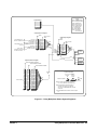
One 2.5-in analog bus cable (E1400-61605) is included to
connect the analog buses of multiple slot-adjacent E1460A
modules or a slot-adjacent E1411B multimeter module. The
analog bus cable, easily installed at the faceplate of the
component card, lets you connect the E1460A with the E1411B
DMM. Using SCPI commands sent to the E1411B, you can
close channels configured as two-wire, three-wire, or
four-wire in the E1460A. It is possible (but less convenient) to
connect the analog bus by attaching your own wiring to the
E1460A and E1411B screw terminals.
The E1460A User Manual contains configuration and
programming examples for one-wire through four-wire
switching modes, cable test, switchbox, scanning, triggering,
and scanning with an external multimeter.
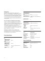
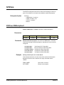
Product Specifications
Input
DC:
Maximum voltage (any
terminal to any other
terminal or chassis):
AC rms:
Maximum voltage (any
terminal to any other
terminal or chassis):
Maximum current
(per channel common,
non-inductive):
Maximum power per
channel:
2
220 Vdc
Maximum thermal offset
per channel, differential
Hi-Lo:
7 µV
Closed channel resistance: <1.5 Ω initial, <3.5 Ω end of life
Insulation resistance
(between any two points): 5x10E6 Ω (40 °C, 95% RH), 5x10E8 Ω (25 °C,
40% RH)
Insulation resistance
(Hi to Lo, power off):
n/a
AC
Minimum bandwidth
(–3 dB, 50 Ω source/load):
Crosstalk (channel-tochannel):
100 kHz:
10 MHz:
Both:
Closed channel
capacitance:
10 MHz (2-wire), 3 MHz (1-wire)
≤60 dB (1-wire), ≤90 dB (2-wire)
n/a
n/a
<650 pF Hi-Lo, <700 pF Lo-Chassis (both in
2-wire mode)
General Characteristics
Relays:
Power down state:
Power up state:
Minimum relay life:
No load:
Rated load:
Screw terminal wire size:
Scanning rate:
Latching armature
Break-before-make
Relays open on power down
Relays open on power up
5x10E6 operations
10E5 operations
16 to 26 AWG (1.5, 1.2, 0.9, 0.75, 0.5 mm)
75 channels/s typ.
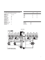
General Specifications
VXI Characteristics
250 V rms
1 Adc/ac rms (< 30 Vdc), 0.3 Adc/ac rms
(<133 Vdc)
40 VA
VXI device type:
Size:
Slots:
Connectors:
Shared memory:
VXI busses:
C-size compatibility:
PDFINFO H 5 6 0 6 - 0 2
Register based, A16, slave only
C
1
P1, P2
None
None
n/a
Instrument Drivers
See the Agilent Technologies Website (http://www.agilent.com/find/
inst_drivers) for driver availability and downloading.
Command module
firmware:
Downloadable
Command module
firmware rev:
A.02
I-SCPI Win 3.1:
Yes
I-SCPI Series 700:
Yes
C-SCPI LynxOS:
Yes
C-SCPI Series 700:
Yes
Panel Drivers:
Yes
VXIplug&play Win
Framework:
Yes
VXIplug&play Win 95/NT
Framework:
Yes
VXIplug&play HP-UX
Framework:
No
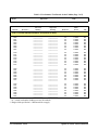
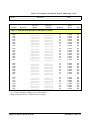
Module Current
+5 V:
+12 V:
–12 V:
+24 V:
–24 V:
–5.2 V
–2 V:
IPM
IDM
0.1
0
0
0
0
0
0
0.1
0
0
0
0
0
0
Cooling/Slot
Watts/slot:
∆P mm H2O:
Air Flow liter/s:
5.00
0.08
0.42
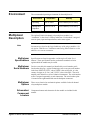
Agilent E1460A
PDFINFO H 5 6 0 6 - 0 3
3
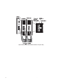
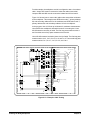
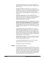
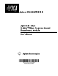
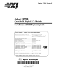
Agilent E1460A with MUX-to-MUX and MUX-to-multimeter analog bus cabling
4
PDFINFO H 5 6 0 6 - 0 4
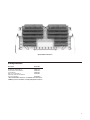
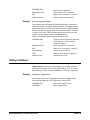
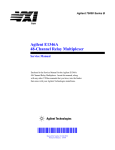
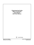
Agilent E1460A Terminal Block
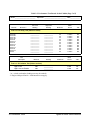
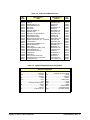
Ordering Information
Description
Product No.
64-Channel Relay Multiplexer
E1460A
Pre-QUIC-type Terminal Block
E1460A 106
Crimp-and-Insert Terminal Block*
E1460A A3E*
Service Manual
E1460A 0B3
Extra Screw Terminal Block
E1460-80011
Extra Crimp-and-Insert Terminal Block
(if ordered separately)*
E1460-80012*
* Note: Crimp-and-Insert Contacts are not included. See the Interconnect
and Wiring section for information on ordering Crimp-and-Insert Contacts.
PDFINFO H 5 6 0 6 - 0 5
5
Agilent Technologies’ Test and Measurement Support, Services,
and Assistance
Agilent Technologies aims to maximize the value you receive, while minimizing
your risk and problems. We strive to ensure that you get the test and
measurement capabilities you paid for and obtain the support you need.
Our extensive support resources and services can help you choose the right
Agilent products for your applications and apply them successfully. Every
instrument and system we sell has a global warranty. Two concepts underlie
Agilent's overall support policy: "Our Promise" and "Your Advantage."
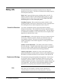
Our Promise
Our Promise means your Agilent test and measurement equipment will meet
its advertised performance and functionality. When you are choosing new
equipment, we will help you with product information, including realistic
performance specifications and practical recommendations from experienced
test engineers. When you receive your new Agilent equipment, we can help
verify that it works properly, and help with initial product operation.
Your Advantage
Your Advantage means that Agilent offers a wide range of additional expert test
and measurement services, which you can purchase according to your unique
technical and business needs. Solve problems efficiently and gain a competitive
edge by contracting with us for calibration, extra-cost upgrades, out-of-warranty
repairs, and onsite education and training, as well as design, system
integration, project management, and other professional engineering services.
Experienced Agilent engineers and technicians worldwide can help you
maximize your productivity, optimize the return on investment of your Agilent
instruments and systems, and obtain dependable measurement accuracy for
the life of those products.
www.agilent.com/find/emailupdates
Get the latest information on the products and applications you select.
Agilent T&M Software and Connectivity
Agilent's Test and Measurement software and connectivity products, solutions
and developer network allows you to take time out of connecting your
instruments to your computer with tools based on PC standards, so you can
focus on your tasks, not on your connections.
Visit www.agilent.com/find/connectivity for more information.
For more assistance with all your test and measurement needs or to find your local
Agilent office go to www.agilent.com/find/assist
Product specifications and descriptions in this document
subject to change without notice.
© Agilent Technologies, Inc. 2005
Printed in the USA May 1, 2005
5965-5606E
Agilent Technologies
E1460A 64-Channel
Relay Multiplexer Module
User’s Manual
Manual Part Number: E1460-90006
Printed September 2012
Printed in Malaysia E0912
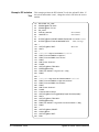
Contents
E1460A Relay Multiplexer User’s Manual
Front Matter....................................................................................................................... 7
Agilent Technologies Warranty Statement ................................................................... 7
Safety Symbols ............................................................................................................ 8
Warnings ...................................................................................................................... 8
Chapter 1- Getting Started ............................................................................................ 11
Using This Chapter .................................................................................................... 11
Multiplexer Description............................................................................................... 11
Multiplexer Components ..................................................................................... 11
Channel Relay Switches ..................................................................................... 12
Control Relays .................................................................................................... 13
Basic Operating Modes ...................................................................................... 14
Configuring the Multiplexer ........................................................................................ 15
Warnings and Cautions ...................................................................................... 15
Setting the Logical Address Switch .................................................................... 16
Setting the Status Register Switch ..................................................................... 17
Setting the Interrupt Priority ................................................................................ 17
Configuring the Switch Card Wire Jumpers ........................................................ 18
Installing the Multiplexer in a Mainframe ............................................................ 21
Connecting the Analog Bus ................................................................................ 22
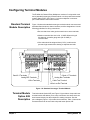
Configuring Terminal Modules.................................................................................... 23
Standard Terminal Module Description ............................................................... 23
Terminal Module Option A3E Description ........................................................... 23
Connecting User Inputs ...................................................................................... 25
Wiring Terminal Modules .................................................................................... 26
Attaching Terminal Modules to the Multiplexer ................................................... 28
Programming the Multiplexer ..................................................................................... 29
Checking SCPI Drivers ....................................................................................... 29
Multiplexer Addressing ....................................................................................... 30
Initial Operation ................................................................................................... 34
Chapter 2 - Using the Relay Multiplexer ...................................................................... 35
Using This Chapter .................................................................................................... 35
Multiplexer Commands/States ................................................................................... 35
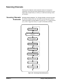
Switching Channels ................................................................................................... 37
Switching Channels Comments .......................................................................... 37
Switching Channels Examples ........................................................................... 38
Scanning Channels .................................................................................................... 43
Scanning Channels Comments .......................................................................... 43
Scanning Channels Examples ............................................................................ 44
Miscellaneous Multiplexer Functions ......................................................................... 51
Using the Scan Complete Bit .............................................................................. 51
Using the Analog Bus ......................................................................................... 52
Saving and Recalling States ............................................................................... 56
Detecting Error Conditions ................................................................................. 56
Synchronizing the Multiplexer ............................................................................. 58
3
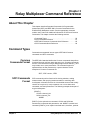
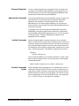
Chapter 3 - Relay Multiplexer Command Reference .................................................. 59
About This Chapter ................................................................................................... 59
Command Types ....................................................................................................... 59
SCPI Commands Reference ..................................................................................... 61
ABORt ........................................................................................................................ 62
ARM ........................................................................................................................... 63
ARM:COUNt ....................................................................................................... 63
ARM:COUNt? ..................................................................................................... 64
INITiate....................................................................................................................... 65
INITiate:CONTinous ........................................................................................... 65
INITiate:CONTinuous? ....................................................................................... 66
INITiate[:IMMediate] ........................................................................................... 66
OUTPut ...................................................................................................................... 68
OUTPut:ECLTrgn[:STATe] .................................................................................. 68
OUTPut:ECLTrgn[:STATe]? ................................................................................ 69
OUTPut[:EXTernal][:STATe] ................................................................................ 69
OUTPut[:EXTernal][:STATe]? .............................................................................. 70
OUTPut:TTLTrgn[:STATe] ................................................................................... 70
OUTPut:TTLTrgn[:STATe]? ................................................................................. 71
[ROUTe:] .................................................................................................................... 72
[ROUTe:]CLOSe ................................................................................................. 72
[ROUTe:]CLOSe? ............................................................................................... 74
[ROUTe:]FUNCtion ............................................................................................. 75
[ROUTe:]FUNCtion? ........................................................................................... 76
[ROUTe:]OPEN ................................................................................................... 77
[ROUTe:]OPEN? ................................................................................................. 79
[ROUTe:]SCAN ................................................................................................... 79
[ROUTe:]SCAN:MODE ....................................................................................... 80
[ROUTe:]SCAN:MODE? ..................................................................................... 82
[ROUTe:]SCAN:PORT ........................................................................................ 82
[ROUTe:]SCAN:PORT? ...................................................................................... 83
STATus....................................................................................................................... 84
STATus:OPERation:CONDition? ........................................................................ 86
STATus:OPERation:ENABle ............................................................................... 86
STATus:OPERation:ENABle? ............................................................................. 86
STATus:OPERation[:EVENt]? ............................................................................ 87
STATus:PRESet ................................................................................................. 87
SYSTem ..................................................................................................................... 88
SYSTem:CDEScription? ..................................................................................... 88
SYSTem:CPON .................................................................................................. 89
SYSTem:CTYPe? ............................................................................................... 89
SYSTem:ERRor? ................................................................................................ 90
TRIGger ..................................................................................................................... 91
TRIGger[:IMMediate] .......................................................................................... 91
TRIGger:SLOPe ................................................................................................. 92
TRIGger:SLOPe? ............................................................................................... 92
TRIGger:SOURce ............................................................................................... 92
TRIGger:SOURce? ............................................................................................. 94
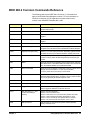
IEEE 488.2 Common Commands Reference ........................................................... 95
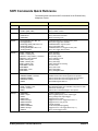
SCPI Commands Quick Reference............................................................................ 96
4
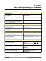
Appendix A - Relay Multiplexer Specifications .......................................................... 97
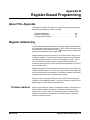
Appendix B - Register-Based Programming ............................................................... 99
About This Appendix .................................................................................................. 99
Register Addressing................................................................................................... 99
The Base Address .............................................................................................. 99
Register Descriptions ............................................................................................... 102
The WRITE Registers ....................................................................................... 102
The READ Registers ........................................................................................ 102
Status/Control Register ..................................................................................... 103
ID and Device Type Registers .......................................................................... 104
Relay Control Registers .................................................................................... 104
Programming Examples........................................................................................... 107
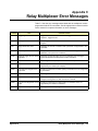
Appendix C - Relay Multiplexer Error Messages ...................................................... 115
Index ............................................................................................................................. 117
5
Notes:
6
AGILENT TECHNOLOGIES WARRANTY STATEMENT
AGILENT PRODUCT: E1460A 64-Channel Relay Multiplexer Module
DURATION OF WARRANTY: 3 years
1. Agilent Technologies warrants Agilent hardware, accessories and supplies against defects in materials and workmanship for the period
specified above. If Agilent receives notice of such defects during the warranty period, Agilent will, at its option, either repair or replace
products which prove to be defective. Replacement products may be either new or like-new.
2. Agilent warrants that Agilent software will not fail to execute its programming instructions, for the period specified above, due to
defects in material and workmanship when properly installed and used. If Agilent receives notice of such defects during the warranty
period, Agilent will replace software media which does not execute its programming instructions due to such defects.
3. Agilent does not warrant that the operation of Agilent products will be interrupted or error free. If Agilent is unable, within a reasonable
time, to repair or replace any product to a condition as warranted, customer will be entitled to a refund of the purchase price upon prompt
return of the product.
4. Agilent products may contain remanufactured parts equivalent to new in performance or may have been subject to incidental use.
5. The warranty period begins on the date of delivery or on the date of installation if installed by Agilent. If customer schedules or delays
Agilent installation more than 30 days after delivery, warranty begins on the 31st day from delivery.
6. Warranty does not apply to defects resulting from (a) improper or inadequate maintenance or calibration, (b) software, interfacing, parts
or supplies not supplied by Agilent, (c) unauthorized modification or misuse, (d) operation outside of the published environmental
specifications for the product, or (e) improper site preparation or maintenance.
7. TO THE EXTENT ALLOWED BY LOCAL LAW, THE ABOVE WARRANTIES ARE EXCLUSIVE AND NO OTHER
WARRANTY OR CONDITION, WHETHER WRITTEN OR ORAL, IS EXPRESSED OR IMPLIED AND AGILENT
SPECIFICALLY DISCLAIMS ANY IMPLIED WARRANTY OR CONDITIONS OF MERCHANTABILITY, SATISFACTORY
QUALITY, AND FITNESS FOR A PARTICULAR PURPOSE.
8. Agilent will be liable for damage to tangible property per incident up to the greater of $300,000 or the actual amount paid for the product
that is the subject of the claim, and for damages for bodily injury or death, to the extent that all such damages are determined by a court
of competent jurisdiction to have been directly caused by a defective Agilent product.
9. TO THE EXTENT ALLOWED BY LOCAL LAW, THE REMEDIES IN THIS WARRANTY STATEMENT ARE CUSTOMER’S
SOLE AND EXLUSIVE REMEDIES. EXCEPT AS INDICATED ABOVE, IN NO EVENT WILL AGILENT OR ITS SUPPLIERS BE
LIABLE FOR LOSS OF DATA OR FOR DIRECT, SPECIAL, INCIDENTAL, CONSEQUENTIAL (INCLUDING LOST PROFIT OR
DATA), OR OTHER DAMAGE, WHETHER BASED IN CONTRACT, TORT, OR OTHERWISE.
FOR CONSUMER TRANSACTIONS IN AUSTRALIA AND NEW ZEALAND: THE WARRANTY TERMS CONTAINED IN THIS
STATEMENT, EXCEPT TO THE EXTENT LAWFULLY PERMITTED, DO NOT EXCLUDE, RESTRICT OR MODIFY AND ARE
IN ADDITION TO THE MANDATORY STATUTORY RIGHTS APPLICABLE TO THE SALE OF THIS PRODUCT TO YOU.
U.S. Government Restricted Rights
The Software and Documentation have been developed entirely at private expense. They are delivered and licensed as "commercial
computer software" as defined in DFARS 252.227- 7013 (Oct 1988), DFARS 252.211-7015 (May 1991) or DFARS 252.227-7014 (Jun
1995), as a "commercial item" as defined in FAR 2.101(a), or as "Restricted computer software" as defined in FAR 52.227-19 (Jun
1987)(or any equivalent agency regulation or contract clause), whichever is applicable. You have only those rights provided for such
Software and Documentation by the applicable FAR or DFARS clause or the Agilent standard software agreement for the product
involved.
E1460A 64-Channel Relay Multiplexer Module User’s Manual
Edition 6
Copyright © 1990, 1992-1995, 2001 Agilent Technologies, Inc. All rights reserved.
7
Documentation History
All Editions and Updates of this manual and their creation date are listed below. The first Edition of the manual is Edition 1. The Edition
number increments by 1 whenever the manual is revised. Updates, which are issued between Editions, contain replacement pages to
correct or add additional information to the current Edition of the manual. Whenever a new Edition is created, it will contain all of the
Update information for the previous Edition. Each new Edition or Update also includes a revised copy of this documentation history page.
Edition 1 . . . . . . . . . . . . . . . . . . . . . . . . . . . . . . . . . . . . . . . . . . . . January, 1990
Edition 2 . . . . . . . . . . . . . . . . . . . . . . . . . . . . . . . . . . . . . . . . . . . . . . . July, 1992
Edition 3 . . . . . . . . . . . . . . . . . . . . . . . . . . . . . . . . . . . . . . . . . . . . . August, 1993
Edition 4 . . . . . . . . . . . . . . . . . . . . . . . . . . . . . . . . . . . . . . . . . . . . October, 1994
Edition 5 . . . . . . . . . . . . . . . . . . . . . . . . . . . . . . . . . . . . . . . . . . November, 1995
Edition 6 . . . . . . . . . . . . . . . . . . . . . . . . . . . . . . . . . . . . . . . . . . . . January, 2001
Edition 6 Rev. 1 . . . . . . . . . . . . . . . . . . . . . . . . . . . . . . . . . . . . . .September 2012
Safety Symbols
Instruction manual symbol affixed to
product. Indicates that the user must refer to
the manual for specific WARNING or
CAUTION information to avoid personal
injury or damage to the product.
Alternating current (AC)
Direct current (DC).
Warning. Risk of electrical shock.
Indicates the field wiring terminal that must
be connected to earth ground before
operating the equipment — protects against
electrical shock in case of fault.
or
Frame or chassis ground terminal—typically
connects to the equipment's metal frame.
Calls attention to a procedure, practice, or
WARNING condition that could cause bodily injury or
death.
Calls attention to a procedure, practice, or
CAUTION condition that could possibly cause damage to
equipment or permanent loss of data.
WARNINGS
The following general safety precautions must be observed during all phases of operation, service, and repair of this product. Failure to
comply with these precautions or with specific warnings elsewhere in this manual violates safety standards of design, manufacture, and
intended use of the product. Agilent Technologies assumes no liability for the customer's failure to comply with these requirements.
Ground the equipment: For Safety Class 1 equipment (equipment having a protective earth terminal), an uninterruptible safety earth
ground must be provided from the mains power source to the product input wiring terminals or supplied power cable.
DO NOT operate the product in an explosive atmosphere or in the presence of flammable gases or fumes.
For continued protection against fire, replace the line fuse(s) only with fuse(s) of the same voltage and current rating and type. DO NOT
use repaired fuses or short-circuited fuse holders.
Keep away from live circuits: Operating personnel must not remove equipment covers or shields. Procedures involving the removal of
covers or shields are for use by service-trained personnel only. Under certain conditions, dangerous voltages may exist even with the
equipment switched off. To avoid dangerous electrical shock, DO NOT perform procedures involving cover or shield removal unless you
are qualified to do so.
DO NOT operate damaged equipment: Whenever it is possible that the safety protection features built into this product have been
impaired, either through physical damage, excessive moisture, or any other reason, REMOVE POWER and do not use the product until
safe operation can be verified by service-trained personnel. If necessary, return the product to Agilent for service and repair to ensure that
safety features are maintained.
DO NOT service or adjust alone: Do not attempt internal service or adjustment unless another person, capable of rendering first aid and
resuscitation, is present.
DO NOT substitute parts or modify equipment: Because of the danger of introducing additional hazards, do not install substitute parts
or perform any unauthorized modification to the product. Return the product to Agilent for service and repair to ensure that safety features
are maintained.
8
Declaration of Conformity
Declarations of Conformity for this product and for other Agilent products may be downloaded from the Internet.
There are two methods to obtain the Declaration of Conformity:
• Go to http://regulations.corporate.agilent.com/DoC/search.htm . You can then search by product
number to find the latest Declaration of Conformity.
• Alternately, you can go to the product web page (www.agilent.com/find/E1460A), click on the
Document Library tab then scroll down until you find the Declaration of Conformity link.
9
Notes:
10
Chapter 1
Getting Started
Using This Chapter
This chapter describes the E1460A 64-Channel Relay Multiplexer module,
shows how to connect external wiring, and shows how to get started
programming the module using Standard Commands for Programmable
Instruments (SCPI). This chapter includes:
• Multiplexer Description . . . . . . . . . . . . . . . . . . . . . . . . . . . . . . . 11
• Configuring the Multiplexer . . . . . . . . . . . . . . . . . . . . . . . . . . . .15
• Configuring Terminal Modules . . . . . . . . . . . . . . . . . . . . . . . . .23
• Programming the Multiplexer . . . . . . . . . . . . . . . . . . . . . . . . . .29
Multiplexer Description
The E1460A is a VXIbus C-Size register-based product that provides
switching (multiplexing) of up to 64 two-wire channels. Switching consists
of connecting a channel’s HI and/or LO line to COM in that bank. The
multiplexer can operate in a C-Size VXIbus mainframe using a command
module (such as an E1406A Command Module).
Multiplexer
Components
The E1460A 64-Channel Relay Multiplexer module consists of a relay
switch card and a standard screw-type terminal module. The E1460A is also
available with Option A3E that provides a crimp-and-insert terminal housing
and connectors. Various configurations can be set by programming (closing)
certain switch card relays, and/or selection of wire jumpers on the relay
switch card and terminal module.
The E1460A is used when high switch densities such as wire harness/cable
testing, semiconductor testing, and/or printed-circuit board testing is
required. Although it is primarily a dual 32-channel two-wire multiplexer,
the module can be configured to perform one-wire, two-wire, three-wire, and
four-wire functions.
By using switch card wire jumpers, the banks can be changed from 1x32
to groups of 1x16 or 1x8. See "Configuring the Switch Card Wire Jumpers"
for more information.
For a SCPI environment, one or more multiplexer modules can be defined
as a switchbox or as a scanning multimeter. For a switchbox configuration,
all multiplexer channels within the instrument can be addressed using a
single interface address. For a scanning multimeter configuration, both the
multimeter and all multiplexer modules within the instrument can be
addressed using a single interface address.
Chapter 1
Getting Started 11
Channel Relay
Switches
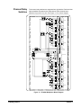
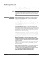
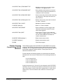
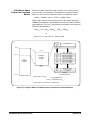
The channel relay switches are separated into eight banks. Each bank has
eight switchable channels and a COM channel. Each channel has a
separate HI (H) and LO (L) line. See Figure 1-1 for a block diagram.
SWITCH CARD
TERMINAL CARD
OPEN
H
L
CLOSED
CH 0990
H
L
H
JM1 JM2 JM3
JM10 JM11
L
H
L
H
L
H
L
H
OPEN
L
H
CLOSED
CH 0991
L
H
JM12 JM13
L
H
L
H
L
H
L
COM
CH 0
BANK 0
CH 7
COM
CH 0
BANK 1
CH 7
COM
CH 0
BANK 2
CH 7
COM
CH 0
BANK 3
CH 7
CABLE T
1W LO REF
H1(1W HI COM)
L1(1W LO COM)
CH 0992
H1
L1
G
CH 0994
CH 0995
ANALOG BUS
H2
L2
G
H
L
H
L
H
JM14 JM15
L
H
L
H
JM4
L
JM5
H
CH0996
L
H
L
CH0993
H
L
H
JM16 JM17
L
H
L
H
L
H
L
COM
CH 0
BANK 4
CH 7
COM
CH 0
BANK 5
CH 7
COM
CH 0
BANK 6
CH 7
COM
CH 0
BANK 7
CH 7
Figure 1-1. E1460A Multiplexer Block Diagram
12 Getting Started
Chapter 1
Banks are arranged as follows:
• Bank 0 includes channels 00 through 07 and COM
• Bank 1 includes channels 10 through 17 and COM
• Bank 2 includes channels 20 through 27 and COM
• Bank 3 includes channels 30 through 37 and COM
• Bank 4 includes channels 40 through 47 and COM
• Bank 5 includes channels 50 through 57 and COM
• Bank 6 includes channels 60 through 67 and COM
• Bank 7 includes channels 70 through 77 and COM
Each channel is switched (connected to its common) by closing the
appropriate (latching) relays. Channels 0 through 7 can be switched to
COM for all banks. Any number of channels in each bank can be connected
to common at a time (except for one-wire mode).
User inputs/outputs to each channel are via wire terminals. When a channel
is closed, it is internally connected to the COM terminal. When a channel is
opened, it is internally disconnected. Open channels are not terminated.
At power-on or reset, all channels are switched open (non-terminated) for all
banks only when using the SCPI or C-SCPI driver. At power-off, all relays
remain in their present state.
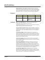
Control Relays
In addition to the channel switching relays, the switch card contains seven
control relays (numbered 0990 to 0996). These relays switch the COM lines
of banks dependent on the mode selected. All relays are automatically
selected when the module is configured for the desired mode, when using
the [ROUTe:]FUNCtion <card_number>, <function> command.
For the stand-alone switchbox configuration, this command must be used in
conjunction with the following commands. If you only use [ROUTe:]OPEN
and [ROUTe:]CLOSe commands, the appropriate control relays must also
be closed with the CLOSe command.
[ROUTe:]SCAN:MODE mode
[ROUTe:]SCAN:PORT
[ROUTe:]SCAN channel_list
For the scanning multimeter configuration, [ROUTe:]FUNCtion
<card_number>, <function> in conjunction with the CONFigure and
INITiate or MEASure multimeter commands closes the appropriate control
relays. See Chapter 3 in this manual and Chapter 5 in the E1326B/E1411B
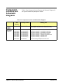
User’s Manual for more information about these commands. Table 1-1
shows the control relay functions.
Chapter 1
Getting Started 13
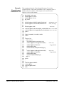
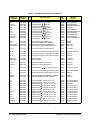
Table 1-1. Control Relay Functions
Control
Relay
Function
0990
Selects HI or LO terminal for one-wire switching.
0991
Connects Cable Test or one-wire LO REF terminal to the
one-wire LO COM terminal.
0992
Connects lower 32 channels (banks 0 - 3) to analog bus.
0993
Connects upper 32 channels (banks 4 - 7) to analog bus.
0994
Connects lower and upper analog buses together.
0995
Connects lower and upper common buses together
(64-channel, two-wire operation).
0996
Connects analog bus Guard to the LO line, on the upper
32 channels (banks 4 to 7).
Basic Operating
Modes
The E1460A uses the channel and control relays on the switch card to
perform four basic operating modes: one-wire, two-wire, three-wire, or
four-wire as shown. Connections to the analog bus (for multimeter
connection) are provided on both the relay switch card and terminal module.
One-wire Mode
Switches either the HI or LO terminal of a channel in banks 0 through 7 to
the one-wire HI COM terminal. One-wire LO COM is switched to the
one-wire LO REF terminal. Only one channel can be switched (closed) at
a time. A maximum of 128 one-wire channels can be switched. SCAN goes
through all channel relay lows. Then, control relay 0990 switches and SCAN
goes through all channel relay highs.
Two-wire Mode
Switches both the HI and LO terminals of a channel in banks 0 through 7
to the HI COM and LO COM terminals. A maximum of 64 two-wire channels
can be switched.
Three-wire Mode
Switches both the HI and LO terminals of a channel in banks 0 through 3
to the HI COM and LO COM terminals. This mode also switches the LO
terminal of the pair channel in banks 4 through 7 to the LO COM terminal.
In addition, the low terminal of the pair channel in banks 4 through 7 can be
connected to the analog bus Guard terminal. Banks are paired 0/4, 1/5, 2/6,
and 3/7. A maximum of 32 three-wire channels can be switched.
Four-wire Mode
14 Getting Started
Switches both the HI and LO terminals of a channel in banks 0 through 3
to the HI COM and LO COM terminals. Also switches the HI and LO
terminals of the pair channel in banks 4 through 7 to the HI COM and LO
COM terminals. Banks are paired 0/4, 1/5, 2/6, and 3/7. A maximum of
32 four-wire channels can be switched.
Chapter 1
Configuring the Multiplexer
This section gives guidelines to configure the relay switch card. See
"Configuring Terminal Modules" for guidelines to configure the terminal
modules. This section includes:
• Warnings and Cautions
• Setting the Logical Address Switch
• Setting the Status Register Switch
• Setting the Interrupt Priority
• Configuring the Switch Card Wire Jumpers
• Installing the Multiplexer in a Mainframe
• Connecting the Analog Bus
Warnings and
Cautions
WARNING
SHOCK HAZARD. Only service-trained personnel who are
aware of the hazards involved should install, remove, or
configure the multiplexer. Before you remove any installed
module, disconnect AC power from the mainframe and from
other modules that may be connected to the multiplexer.
WARNING CHANNEL WIRING INSULATION. All channels that have a
common connection must be insulated so that the user is
protected from electrical shock in the event that two or more
channels are connected together. This means wiring for all
channels must be insulated as though each channel carries the
voltage of the highest voltage channel.
CAUTION MAXIMUM INPUTS. The maximum voltage that can be applied to any
terminal is 220 Vdc/250 Vrms. The maximum current that can be applied
to any terminal is 1A at 30 Vdc/Vrms, or 0.3 A at 250 Vdc/Vrms. The
maximum power that can be applied to any terminal is 40 VA.
CAUTION STATIC ELECTRICITY. Static electricity is a major cause of component
failure. To prevent damage to the electrical components in the multiplexer,
observe anti-static techniques whenever removing a module from the
mainframe or whenever working on a module.
Chapter 1
Getting Started 15
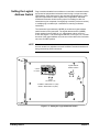
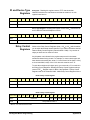
Setting the Logical
Address Switch
Plug-in modules installed in an mainframe or used with a command module
are treated as independent instruments each having a unique secondary
GPIB address. Each instrument is also assigned a dedicated error queue,
input and output buffers, status registers and, if applicable, dedicated
mainframe/command module memory space for readings or data. An
instrument may be composed of a single plug-in module (such as a counter)
or multiple plug-in modules (for a switchbox or scanning multimeter
instrument).
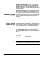
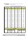
The instrument logical address (LADDR) is set with the logical address
switch located on the instrument. The logical address switch (LADDR)
factory setting for the E1460A is 112. Valid address values are from 1
to 255. See Figure 1-2 to set the logical address. From Figure 1-2, note that
the value of the logical address set is the sum of the values of the switches
set to the CLOSED position.
NOTE The address switch selected value must be a multiple of 8 if the module is
the first module in a switchbox used with a VXIbus command module and
being instructed by SCPI commands.
Logical Address = 112
0=OPEN
Logical Address
Switch Location
1
2
4
8
16
32
64
128
1=CLOSED
16+32+64=112
CLOSED = Switch Set To 1 (ON)
OPEN = Switch Set To 0 (OFF)
Figure 1-2. Setting the Logical Address Switch
16 Getting Started
Chapter 1
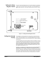
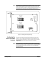
Setting the Status
Register Switch
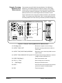
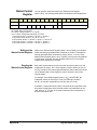
Four bits of the Status Register (bits 10-13) define whether the multiplexer
module is set for one-wire, two-wire, three-wire, or four-wire switching. To
ensure proper operation, set the status register switch as shown in Figure
1-3.
0
0
0
1
0
0
0
0
0
1
0
1
0
1
0
1
1
0
1
0
0
1
1
0
1-wire, 128-channel
2-wire, 64-channel
2-wire, Dual 32-channel
3-wire, 32-channel
4-wire, 32-channel
Example shows
switch set
to 4-wire
13
10
Status Register
Switch Location
Figure 1-3. Setting the Status Register Switch
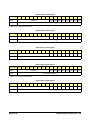
Setting the Interrupt
Priority
The multiplexer module generates an interrupt after a channel has been
closed. These interrupts are sent to, and acknowledgments are received
from, the command module (such as an E1406A) via the VXIbus backplane
interrupt lines.
For most applications where the multiplexer module is installed in a C-Size
mainframe, the interrupt priority jumper does not have to be moved. This is
because the VXIbus interrupt lines have the same priority, and interrupt
priority is established by installing modules in slots numerically closest to
the command module. Thus, slot 1 has a higher priority than slot 2, slot 2
has a higher priority than slot 3, etc.
See Figure 1-4 to change the interrupt priority. You can select eight different
interrupt priority levels. Level 1 is the lowest priority and Level 7 is the
highest priority. Level X disables the interrupt. The module’s factory setting
is Level 1. To change, remove the 4-pin jumper from the old priority location
and reinstall in the new priority location. If the 4-pin jumper is not used, the
two jumper locations must have the same interrupt priority level selected.
Chapter 1
Getting Started 17
NOTE The interrupt priority jumper MUST be installed in position 1 when using the
E1406 command module. Level X interrupt priority should not be used
under normal operating conditions. Changing the priority level jumper is not
recommended. Do not change unless specifically instructed to do so.
7
6
5
4
3
2
1
X
IRQ
Using 4-Pin
Jumper
Interrupt
Priority
Location
7
6
5
4
3
2
1
X
IRQ
Using 2-Pin
Jumper
Figure 1-4. Setting the Interrupt Priority
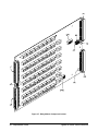
Configuring the
Switch Card Wire
Jumpers
The relay switch card has thirteen factory-installed wire jumpers (see
Figures 1-1 and 1-5) that connect COM lines of banks together to form
dual 1x32 channel configurations. These wire jumpers can be changed to
reconfigure the switch card to various 8-channel or 16-channel
configurations.
NOTE It is only necessary to change the wire jumpers when reconfiguring the
switch card for groups of eight or 16 channels (from 32). DO NOT CHANGE
the wire jumper positions unless instructed to do so in the applicable
operating procedures.
18 Getting Started
Chapter 1
Wire Jumper Functions
With the exception of JM1, wire jumpers are changed in pairs. Functions of
the wire jumpers are:
• JM1: Used during cable test (see Chapter 2)
• JM2/JM3: Used to connect the COM lines of bank pairs 0/1 and 2/3
• JM4/JM5: Used to connect the COM lines of bank pairs 4/5 and 6/7
• JM10/JM11: Used to connect the COM lines of banks 0 and 1
• JM12/JM13: Used to connect the COM lines of banks 2 and 3
• JM14/JM15: Used to connect the COM lines of banks 4 and 5
• JM16/JM17: Used to connect the COM lines of banks 6 and 7
Jumper Location
Figure 1-5. Switch Card Wire Jumper Settings
Reconfiguring the Relay
Switch
To reconfigure the relay switch card:
1 Position the switch card on a flat surface. Using a TORX T-10 driver,
remove the six screws on the shield and carefully lift the shield to
expose the printed circuit board.
2 Configure the wire jumpers as required using Table 1-2. If you install
new jumpers, use zero-ohm resistors or No. 22 AWG copper wire.
For example, to configure banks 0, 1, 2, and 3 as 1x8 multiplexers
and banks 4, 5, 6, and 7 as 1x16 multiplexers, jumper positions are:
Jumpers = JM14,15,16,17 and No Jumpers = JM2,3,4,5,10,11,12,13.
3
Chapter 1
Replace the shield and re-install the six screws.
Getting Started 19
NOTE When wire jumpers JM10 through JM17 are removed, the odd-numbered
banks can no longer be connected to the analog bus. For example, if JM10
and JM11 are removed, then bank 1 can no longer be connected to the
analog bus terminals (except through user wiring).
When wire jumpers JM2 through JM5 are removed, banks 2/3 and 4/5,
respectively, can no longer be connected to the analog bus. For example,
if JM2 and JM3 are removed, then banks 2 and 3 can no longer be
connected to the analog bus terminals (except through user wiring).
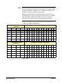
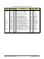
Table 1-2. Jumper Configurations
JM Number ( 0 = Jumper, 1 = No Jumper)
Bank Number = Jumper
Configuration
Bank 0
Bank 1
Bank 2
Bank 3
1
2
3
4
5
10
11
12
13
14
15
16
17
1x32*
1x32*
1x32*
1x32*
-
0
0
-
-
0
0
0
0
-
-
-
-
1x16
1x16
1x16
1x16
-
1
1
-
-
0
0
0
0
-
-
-
-
1x8
1x8
1x8
1x8
-
1
1
-
-
1
1
1
1
-
-
-
-
1x8
1x8
1x16
1x16
-
1
1
-
-
1
1
0
0
-
-
-
-
1x16
1x16
1x8
1x8
-
1
1
-
-
0
0
1
1
-
-
-
-
Bank Number = Jumper
Configuration
JM Number ( 0 = Jumper, 1 = No Jumper)
Bank 4
Bank 5
Bank 6
Bank 7
1
2
3
4
5
10
11
12
13
14
15
16
17
1x32*
1x32*
1x32*
1x32*
-
-
-
0
0
-
-
-
-
0
0
0
0
1x16
1x16
1x16
1x16
-
-
-
1
1
-
-
-
-
0
0
0
0
1x8
1x8
1x8
1x8
-
-
-
1
1
-
-
-
-
1
1
1
1
1x8
1x8
1x16
1x16
-
-
-
1
1
-
-
-
-
1
1
0
0
1x16
1x16
1x8
1x8
-
-
-
1
1
-
-
-
-
0
0
1
1
* factory setting
20 Getting Started
Chapter 1
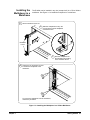
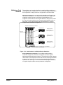
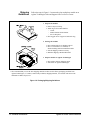
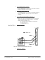
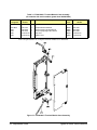
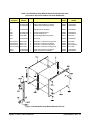
Installing the
Multiplexer in a
Mainframe
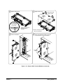
1
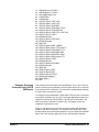
The E1460A can be installed in any slot (except slot 0) in a C-Size VXIbus
mainframe. See Figure 1-6 to install the multiplexer in a mainframe.
Set the extraction levers out.
2
Slide the multiplexer into any slot
(except slot 0) until the backplane
connectors touch.
Extraction
Levers
3
4
Seat the multiplexer into
the mainframe by pushing
in the extraction levers.
Tighten the top and bottom screws
to secure the multiplexer to the
mainframe.
To remove the multiplexer from the mainframe,
reverse the procedure.
Figure 1-6. Installing the Multiplexer in a VXIbus Mainframe
Chapter 1
Getting Started 21
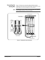
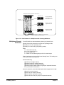
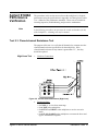
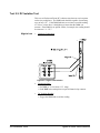
Connecting the
Analog Bus
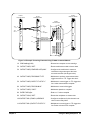
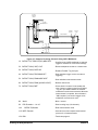
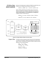
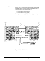
Figure 1-7 shows how to connect the analog bus between multiple
multiplexer modules and to the E1411B multimeter. Use cable (part number
E1400-61605) to connect the analog bus to all the modules.
NOTE The analog bus can also be wired to the terminal module. See "Standard
Terminal Module Description" for more information.
Multimeter Module
Command Module
or VXI Controller
Daisy-Chain Cables
(E1400-61605)
Multiplexer Modules
Figure 1-7. Analog Bus Cable Connections
22 Getting Started
Chapter 1
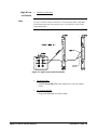
Configuring Terminal Modules
The E1460A 64-Channel Relay Multiplexer consists of a relay switch card
and a (standard) screw-type terminal module or a crimp-and-insert terminal
module (Option A3E). See Figure 1-10 for the multiplexer’s connector
pin-out that mates to the terminal module.
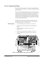
Standard Terminal
Module Description
Figure 1-8 shows the standard screw-type terminal module connectors and
associated bank numbers, channel numbers, and line designations. Use the
following guidelines for wiring connections:
• Be sure that wires make good connections on screw terminals.
• Maximum terminal wire size is No. 16 AWG. When wiring all
64-channels, a smaller gauge wire (20-22 AWG) is
recommended.
• Wire ends should be stripped 6mm (0.25 in.) and tinned to
prevent single strands from shorting to adjacent terminals.
Bank 0-3 Terminals
Bank 4-7 Terminals
Analog Bus Terminals
1-Wire Terminals
Analog Bus Terminals
Cable Test Terminal
1-Wire Low Ref Terminal
Figure 1-8. Standard Screw-type Terminal Module
Terminal Module
Option A3E
Description
Chapter 1
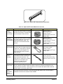
Terminal module Option A3E (see Figure 1-9) provides a crimp-and-insert
terminal module that allows you to crimp connectors onto wires which are
then inserted directly into the multiplexer’s mating connector. See the
pin-out diagram (Figure 1-10) to make the connections. Table 1-3 shows the
accessories that can be used with crimp-and-insert Option A3E.
Getting Started 23
Figure 1-9. Option A3E Crimp-and-Insert Connector
Table 1-3. Option A3E Terminal Module Accessories
Accessory
Single-
Conductor
and Contact
Description
Picture
Specifications
A crimp-and-insert contact is crimped
onto one end of a wire. The other end
is not terminated. Order 91510A.
Length: 2 meters
Wire Gauge: 24 AWG
Quantity: 50 each
Insulation Rating: 105oC max
Voltage: 300 V
Shielded-
A crimp-and-insert contact is crimped
Twisted-Pair onto each conductor at one end of a
and Contacts shielded-twisted-pair cable. The
other end is not terminated. Order
91511A.
Length: 2 meters
Wire Gauge: 24 AWG
Outside Diameter: 0.1 inches
Quantity: 25 each
Insulation Rating: 250oC max
Voltage: 600 V
Jumper Wire A crimp-and-insert contact is crimped
and Contacts onto each end of a single conductor
jumper wire. This jumper is typically
used to tie two pins together in a
single crimp-and-insert connector.
Order 91512A.
Length: 10 cm
Wire Gauge: 24 AWG
Quantity: 10 each
Insulation Rating: 105oC max
Voltage: 300 V
Crimp-and-
Insert
Contacts
These contacts may be crimped onto
a conductor and then inserted into a
crimp-and-insert connector. The
crimp tool kit is required to crimp the
contacts onto a conductor and
remove the contact from the
connector. Order 91515A.
Wire Gauge Range: 20-26 AWG
Quantity: 250 each
Plating: Gold Plated Contact
Maximum Current: 2A at 70oC
Crimp-and-
Insert Tools
The hand crimp tool (part number 91518A) is used for crimping contacts onto a conductor.
The pin extractor tool (part number 91519A) is required for removing contacts from the
crimp-and-insert connector. These products are not included with Option A3E or with the
terminal option accessories listed earlier.
Extra
Crimp-and-
Insert
Connectors
The crimp-and-insert connector is normally supplied with Option A3E. Contact Agilent if
additional connectors are needed. Order 91484B.
24 Getting Started
Chapter 1
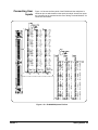
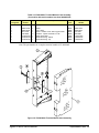
Connecting User
Inputs
Figure 1-10 shows the front panel of the E1460A and the multiplexer’s
connector pin-out which mates to the terminal module. Actual user inputs
are connected to the terminal module. See "Wiring Terminal Modules" for
connection information.
Figure 1-10. E1460A Multiplexer Pin-Out
Chapter 1
Getting Started 25
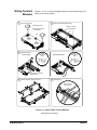
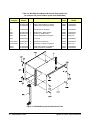
Wiring Terminal
Modules
1
Figures 1-11 and 1-12 show suggested steps to connect field wiring (user
inputs) to a terminal module.
2
Remove Clear Cover
Remove and Retain Wiring Panel
A. Release Screws
Remove 1 of the 3
wire exit panels
B. Press Tab Forward
and Release
Tab
3
Make Connections
Screw-Type
Use wire
Size 16-26
AWG
Crimp-and-Insert
Use wire
Size 22-26
AWG
2.5mm
0.1"
5mm
0.2"
VW1 Flammability
Rating
Insert wire into terminal.
Tighten screw.
4
Install Connectors (Crimp-and-Insert)
5
Route Wiring
Tighten wraps to
secure wires
Figure 1-11. Steps to Wire Terminal Modules
Continued on next page
26 Getting Started
Chapter 1
6
7
Replace Wiring Panel
Replace Clear cover
B. Press down and
tighten screws
Cut required
holes in panels
for wire exit
Keep wiring panel exit
hole as small as
possible
8
Install on Multiplexer
A. Hook in the top cover
tabs onto the fixture.
9
Push in the Extraction Levers to Lock the
Terminal Module onto the Multiplexer
Extraction
Levers
Figure 1-12. Steps to Wire Terminal Modules (continued)
Chapter 1
Getting Started 27
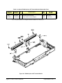
Attaching Terminal
Modules to the
Multiplexer
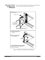
1
Figure 1-13 shows how to attach a terminal module to the multiplexer and
how to remove a terminal module from the multiplexer.
Extend the extraction levers on the
terminal module.
Extraction Lever
Use small screwdriver
to release the two
extraction levers
Extraction Lever
2
Align the terminal module connectors
to the multiplexer connectors.
3
Apply gentle pressure to attach
the terminal module to the
multiplexer.
4
Push in the extraction levers
to lock the terminal module
onto the multiplexer.
Extraction
Levers
To remove the terminal module from the multiplexer,
use a small screwdriver to release the two extraction
levers and push both levers out simultaneously
to free it from the multiplexer.
Figure 1-13. Attaching a Terminal Module to the Multiplexer
28 Getting Started
Chapter 1
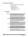
Programming the Multiplexer
The multiplexer modules are programmed using either a switchbox or
scanning multimeter configuration. To program the multiplexer modules
using SCPI commands, you must choose the controller language, interface
address, and SCPI commands to be used. Guidelines to choose SCPI
commands for the multiplexer follow.
NOTE This discussion applies only to SCPI programming. See Appendix B Register-Based Programming for details on multiplexer module registers.
Checking SCPI
Drivers
The E1460A operates with Switchbox Driver Revision A.08.03 or later or
with Scanning Voltmeter Driver Revision A.06.03 or later. The E1460A may
be recognized by earlier driver revisions, but will not operate properly.
Before using the E1406A, you should check your driver revision and, if
necessary, load a new driver.
This procedure shows a way to download SCPI drivers to the E1406A.
SCPI Instrument Drivers and the VXI Installation Consultant (VIC) are on
the Agilent Technologies Universal Instrument Drivers CD. For the latest
information on drivers, see the Agilent web site:
http://www.agilent.com/find/inst_drivers
What are SCPI Device
Drivers?
Agilent register-based modules are supported by Standard Commands for
Programmable Instruments (SCPI) drivers. These drivers reside in E1406A
Command Module non-volatile memory. If you add a new register-based
module to an existing VXI system and plan to program the module using
SCPI, the firmware in your command module may need to be upgraded to
accommodate the new module. You can download new drivers into
non-volatile memory from controllers running Windows, BASIC, or IBASIC.
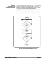
Checking the SCPI Driver
Revision
This procedure describes how to decide which E1460A driver to use, how to
check the currently installed driver, and how to determine if you need to
download a new driver. If you determine that you need to install a new driver,
see "Downloading a New Driver".
1 Decide whether to use the VOLTMTR or SWITCH driver. Use the
VOLTMTR driver if you intend to use the E1460A in combination
with the E1326B or E1411B multimeter in a Scanning Voltmeter
configuration. In this configuration, the E1460A scans measurement
channels and sends the signals to the multimeter where the
measurements take place. Use the SWITCH driver for all other
applications (all non-Scanning Voltmeter applications).
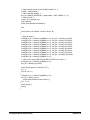
2 Check the currently installed driver revision numbers by sending the
DIAG:DRIV:LIST? command to the command module (the command
module is usually at GPIB address 70900). A typical result follows.
The specific result depends on the specific drivers previously loaded
into your command module.
Chapter 1
Getting Started 29
SYSTEM,E1406A,A.08.00,ROM;IBASIC,IBASIC,A.O4.02,ROM;
VOLTMTR,E1326B,A.06.00,ROM;
SWITCH,SWITCHBOX,A.07.00,ROM;
COUNTER,E1332A,A.04.02,ROM;E1333A,A.04.02,ROM;
DIG_I/O,E1330A,A.O4.03,ROM;D/A,E1328A,A.04.02,ROM
3 Determine whether to install a new driver. The E1460A requires a
SWITCH Driver Revision of A.08.03 or later or a VOLTMTR Driver
Revision A.06.03 or later. In the example response above, the
currently installed drivers are:
VOLTMTR,E1326A,A.06.00,ROM
SWITCH,SWITCHBOX,A.07.00,ROM
In this example, you must download a new SWITCH or VOLTMTR driver
(depending upon which driver you chose in Step 1).
Downloading a New
Driver
To download a new driver, choose your operating system and interface from
the following list and follow the related instructions.
Windows via GPIB or RS-232. (For the fastest download, use GPIB rather
than RS-232.) Use the VXI Installation Consultant (VIC). VIC is a hardware
installation program that helps you configure and install VXI instruments and
can also download DOS-formatted instrument drivers. VIC downloads
drivers during the configuration process and stores a copy of the driver in the
C:\VIC\DRIVERS directory the FIRST TIME the instrument is configured.
NOTE If you are updating an already installed driver, the new driver must be
downloaded using the VIC Driver Download utility. Instructions for using
VIC and its Driver Download utility are contained in VIC’s on-line help.
All other operating systems/interfaces. See the Installing SCPI Device
Drivers Installation Note (shipped with the downloadable drivers).
Multiplexer
Addressing
SCPI Commands Format
To address specific channels within a multiplexer module in either switchbox
or scanning multimeter configuration, you must end the appropriate SCPI
command string to the switchbox or scanning multimeter (for example,
CLOSe, OPEN, etc.) and specify the specific channel address.
You can send SCPI commands in either short or long form. A long form
example is CLOSe(@123). The same command shown without the lower
case letters is the short form. The command then becomes CLOS(@123).
Some commands are shown with brackets ([ ]). These are implied
commands that you do not need to execute. The brackets are not part
of the command and are not sent to the instrument.
For example, the ROUTe command is an implied command and is shown
here as [ROUTe:]CLOS(@123). Thus, to execute these commands, you
can just enter CLOS(@123). See Chapter 3 for more information about
SCPI commands and how to send them.
30 Getting Started
Chapter 1
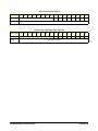
Multiplexer Card
Numbers
The multiplexer card number identifies the module within a switchbox or
scanning multimeter configuration. The card number assigned depends on
the configuration. Leading zeroes can be ignored for the card number.
Switchbox Configuration. In a single-module switchbox configuration, the
card number is always 01. In a multiple-module switchbox configuration,
multiplexer modules are set to successive logical addresses. The
multiplexer module with the lowest logical address is always card number
01. The card number with the next successive logical address is 02, etc..
See Figure 1-14 for card numbers and logical addresses of a typical
multiple-module switchbox configuration.
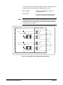
Multiple-Module Switchbox Card Numbers
Card Number 01
1
2
4
8
16
32
64
128
Command
Module
Multiplexer Module
Logical Address = 112
Secondary Address = 14
Card Number 02
1
2
4
8
16
32
64
128
Multiplexer Module
Logical Address = 113
Card Number 03
1
2
4
8
16
32
64
128
Multiplexer Module
Logical Address = 114
Note: Physical placement of the Module in the Logical Address
order is not required, but is recommended.
Figure 1-14. Card Numbers in a Multiple-Module Switchbox
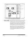
Scanning Multimeter Configuration. In a multiple-module scanning
multimeter configuration, modules are assigned successive logical
addresses beginning with the multimeter. The multimeter module is always
card number 00, the multiplexer module with the next lowest logical address
is always card number 01, the next successive logical address is card
number 02, etc. See Figure 1-15 for card numbers and logical addresses
of a typical multiple-module scanning multimeter configuration.
Chapter 1
Getting Started 31
Multiple-Module Scanning Multimeter Card Numbers
Card Number 00
HP E1411B Multimeter
Logical Address = 24
Secondary Address = 03
1
2
4
8
16
32
64
128
Command
Module
Card Number 01
1
2
4
8
16
32
64
128
Multiplexer Module #1
Logical Address = 25
Card Number 02
1
2
4
8
16
32
64
128
Multiplexer Module #2
Logical Address = 26
Note: Physical placement of the Module in the Logical Address
order is not required, but is recommended.
Figure 1-15. Card Numbers in a Multiple-module Scanning Multimeter
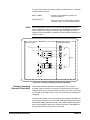
Multiplexer Channel
Addresses
For the E1460A, the channel address (channel_list) has the form:
(@ssbc) for two-wire, three-wire, and four-wire operating modes
(@ss0hbc) for one-wire operating mode
(@ss099c) for control relays (all operating modes)
where
ss = card number (01-99)
0h = LO or HI terminal (0-1)
b = bank number (0-7)
c = number 0-7 for switching relays or 0-6 for control relays
Channel addresses can be specified in the following forms. The leading zero
in the card number can be ignored.
One-wire mode only
(@ss0hbc) for a single channel;
(@ss0hbc,ss0hbc) for multiple channels;
(@ss0hbc:ss0hbc) for sequential channels;
(@ss0hbc:ss0hbc,ss0hbc:ss0hbc) for groups of sequential channels
or any combination of the above.
Two-wire, three-wire, or four-wire modes (and control relays) where b = 099
(@ssbc) for a single channel;
(@ssbc,ssbc) for multiple channels;
(@ssbc:ssbc) for sequential channels;
(@ssbc:ssbc,ssbc:ssbc) for groups of sequential channels;
32 Getting Started
Chapter 1
or any combination of the above.
Low or High Terminal Number
The LO or HI terminal number is specified for one-wire mode only and
identifies what terminal will be used during one-wire switching. This number
can be omitted when the low terminal is the desired selection. Only valid
terminals can be accessed in a channel list. 00 is specified to use the LO (L)
terminal of the bank and channel selected. Defaults to LO terminal if not
entered. 01 is specified to use the HI (H) terminal of the bank and channel
selected.
Bank Number
The bank number identifies what bank of eight channels will be affected
during switching. The bank numbers are 0 to 7 for one-wire and two-wire
modes and 0 to 3 for three-wire and four-wire modes. Only valid banks can
be accessed in a channel list. Closing, opening, or querying banks 4 to 7
when operating in three-wire and four-wire modes will generate an error.
Channel Number
The channel number identifies what channel will be switched to its COM
terminal. Channel numbers are 0 to 7. Only valid channels can be accessed
in a channel list. When switching the control relays, the channel number
(0 to 6) identifies which control relay will be switched (see Figure 1-1).
Examples: Multiplexer
Module Channel List
One-wire operating mode:
CLOSe (@10173)
!Connect card 01, bank 7, channel 3 HI
terminal to the one-wire HI COM terminal
Two-wire operating mode:
CLOSe (@173,176)
!Connect card 01, bank 7, channels 3 and
6 HI and LO terminals, to bank 7 HI and LO
COM terminals
Three-wire operating mode:
CLOSe(@133:136)
!Connect card 01, bank 3, channels 3
through 6 HI and LO terminals, to bank 3 HI
and LO COM terminals. Also connect bank
7, channels 3 through 6 LO terminal, to
bank 7 LO COM terminal.
Four-wire operating mode:
CLOSe(@133:136,233:236)
!Connect cards 01 and 02, bank 3,
channels 3 through 6 HI and LO terminals,
to bank 3 HI and LO COM terminals. Also,
connect bank 7, channels 3 through 6 HI
and LO terminals, to bank 7 HI and LO
COM terminals.
Control relays:
CLOSe (@10995)
Chapter 1
!Connect the upper and lower 32 channels
together for a 64-channel two-wire
Getting Started 33
multiplexer
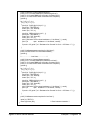
Initial Operation
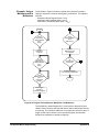
You can use the following example program to verify initial multiplexer
module operation by closing a channel and querying channel closure. The
example first resets the switchbox and then closes bank 0, channel 2 of a
single multiplexer module (card number 1) in the switchbox.
The program next queries the channel closure state. A returned "1" shows
that the command to close the channel has been sent to the switchbox.
A returned "0" shows that the command to close the channel has not been
sent to the switchbox.
BASIC is used as the program language. The computer interfaces to the
mainframe using GPIB with interface select code 7, primary address 09,
and secondary address 14. This example rsesets the switchbox and closes
card 01 bank 0 channel 2 (to COM).
10 OUTPUT 70914;"RST"
20 OUTPUT 70914;"CLOS(@102)"
30
40
50
60
34 Getting Started
OUTPUT 70914;"CLOS? (@102)"
ENTER 70914;Value
PRINT Value
END
!Reset the module, set all relays to open
!Connect bank 0 channel 2 HI and LO
terminals to bank 0 to COM HI and LO
terminals
!Query channel 02
!Enter results into Value
!Display results (should return "1")
Chapter 1
Chapter 2
Using the Relay Multiplexer
Using This Chapter
This chapter shows how to use the Relay Multiplexer module, including:
• Multiplexer Commands/States . . . . . . . . . . . . . . . . . . . . . . . . 35
• Switching Channels . . . . . . . . . . . . . . . . . . . . . . . . . . . . . . . . .37
• Scanning Channels . . . . . . . . . . . . . . . . . . . . . . . . . . . . . . . . .43
• Miscellaneous Multiplexer Functions . . . . . . . . . . . . . . . . . . . 51
Multiplexer Commands/States
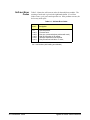
This section summarizes Relay Multiplexer module commands, queries,
and reset states. Table 2-1 shows multiplexer commands used in this
chapter. See Chapter 3 for additional information about the commands.
Table 2-1. Selected Multiplexer Commands Used in Chapter 2
Command
Description
INITiate[:IMMediate]
Starts the scan sequence and closes the first channel in the channel_list.
OUTPut:TTLTrgn[:STATe] ON
Enables selected output to trigger pulses from the TTL Trigger bus line specified.
OUTPut:EXTernal][:STATe] ON
Enables selected output to trigger pulses from command module’s "Trig Out" port.
[ROUTe:]CLOSe <channel_list>
Closes the channels in the channel_list.
[ROUTe:]CLOSe? <channel_list>
Queries the state of the closed channels in the channel_list.
[ROUTe:]FUNCtion
<card_number>,<function>
Sets the operating mode to one-wire, two-wire, three-wire, or four-wire.
[ROUTe:]OPEN <channel_list>
Opens the channels in the channel_list.
[ROUTe:]SCAN <channel_list><
Defines the channels to be scanned. Channels specified in the channel_list
are closed one at a time.
[ROUTe:]SCAN:PORT
Closes bank COM terminals to the analog bus during a scan.
[ROUTe:]SCAN:MODE
Sets the scan mode to volts, 2-wire ohms, or 4-wire ohms.
TRIGger:SOURce <source>
Selects the trigger source to advance the scan.
*CLS
Clears all switchbox status registers and error queue.
*ESE
Enables event status register.
*RST
Resets the hardware and software to a known state.
*SRE
Enables status register.
Chapter 2
Using the Relay Multiplexer 35
Table 2-2 summarizes the query commands you can use to determine the
configuration or state of the multiplexer. All commands put the data into the
output buffer where you can retrieve it to your computer.
Table 2-2. Multiplexer Query Commands
Command
Description
Command
Description
ARM:COUN?
Number of Scanning Cycles
SCAN:PORT?
Scanning Port Selected
CLOS?
Channel Closed
STAT:OPER:ENAB?
Status Operation Enable
FUNC?
Operating Mode Selected
STAT:OPER:EVEN?
Status Operation Event
OPEN?
Channel Open
SYST:CDES? <number>
Module Description
INIT:CONT?
Scanning State
SYST:CTYP? <number>
Module Type
OUTP:ECLTrgn?
ECL Trigger Output State
SYST:ERR?
System Error
OUTP:EXT?
External Trigger Output State
TRIG:SLOP?
Trigger Slope
OUTP:TTLTrgn?
TTL Trigger Output State
TRIG:SOUR?
Trigger Source
SCAN:MODE?
Scanning Mode Selected
Table 2-3 lists the parameters and default values for the functions described
in this chapter. When the multiplexer is switched on or *RST (reset), all
bank channels are set to open and the current channel_list for scanning is
invalidated.
Table 2-3. Multiplexer Reset Conditions
Parameter
Default
Description
ARM:COUNt
1
Number of scanning cycles is one
INITiate:CONTinuous
OFF
Number of scanning cycles is set by ARM:COUNt
OUTPut:ECLTrgn[:STATe]
OFF
Trigger output from ECLT sources is disabled
OUTPut[:EXTernal][:STATe]
OFF
Trigger output from external sources is disabled
OUTPut:TTLTrgn[:STATe]
OFF
Trigger output from TTLT sources is disabled
[ROUTe:]SCAN:MODE
NONE
Channel list volts/ohms measurements disabled
[ROUTe:]SCAN:PORT
NONE
Analog bus port connection disabled
TRIGger:SOURce
IMM
Will advance scanning cycles automatically
36 Using the Relay Multiplexer
Chapter 2
Switching Channels
For general purpose switching, you can switch channels (connect or
disconnect signals) in one-wire, two-wire, three-wire, or four-wire operating
modes by opening or closing specific channel(s).
NOTE
Switching Channels
Comments
For more information, see the [ROUTe:]FUNCtion command. There is no
need to send the [ROUTe:]FUNCtion command if the status register switch
(see "Setting the Status Register Switch") is set to the correct operating
mode.
Setting Multiplexer Function. Use FUNCtion <card_number>,<function> to
configure the Relay Multiplexer, where <function> = WIRE1 | WIRE2 |
WIRE2X64 | WIRE3 | WIRE4.
Opening/Closing Channels. Use CLOSe <channel_list> to close bank
channel(s) and OPEN <channel_list> to open bank channel(s). Channel_list
has the form (@ss0hbc) where ss = card number (00-99), 0h = one-wire
mode only HI/LO switching (00 or 01), b = bank number (0-7), and c =
channel number (0-7).
Opening/Closing Multiple Channels. To close or open multiple channels,
place a comma (,) between the channel numbers. To close or open a range
of channels, place a colon (:) between the channel numbers. You can do this
for both single or multiple module switchboxes. See [ROUTe:]OPEN and
[ROUTe:]CLOSe for additional information.
Querying Open/Closed Channels. The CLOS? <channel_list> and OPEN?
<channel_list> commands determine if the channel in the channel_list is
open or closed, respectively. (The query command does not determine if, in
the event of a hardware failure, the channel remains open/closed.) See
[ROUTe:]OPEN? and [ROUTe:]CLOSe? for additional information.
Switching Control Relays. The control relays 0990 to 0996 can also be
switched using the OPEN and CLOSe commands, provided the FUNCtion
command is executed first. See [ROUTe:]OPEN and [ROUTe:]CLOSe for
additional information.
FRES: When operating in one-wire mode, 4-wire resistance measurement
(FRES) is not supported. See the [ROUTe:]SCAN:MODE command for
additional information.
Analog Bus Connection When Scanning. In all four modes of operation, the
analog bus can be connected during a scan using the SCAN:PORT
command. In three-wire mode, the paired bank (4-7) channel LO terminal
can be connected to the analog bus Guard terminal. See the
[ROUTe:]SCAN:PORT command for additional information.
Chapter 2
Using the Relay Multiplexer 37
Analog Bus Connection When Not Scanning. When opening and closing
individual channels in all four modes of operation, the analog bus can be
connected by switching the control relays (0992-0994, 0996) using the
OPEN and CLOSe commands. See [ROUTe:]OPEN and [ROUTe:]CLOSe
for additional information.
Relay Switch Card Configuration. In all modes of operation the relay switch
card wire jumpers can be changed to 1x8 or 1x16 configurations as required.
See “Configuring the Switch Card Wire Jumpers” for additional information.
Switching Channels
Examples
Four example programs follow that illustrate one-wire, two-wire, three-wire,
and four-wire modes of operation for switching multiplexer channels. The
examples are:
• Example: Switching Channels (One-Wire)
• Example: Switching Channels (Two-Wire)
• Example: Switching Channels (Three-Wire)
• Example: Switching Channels (Four-Wire)
Example: Switching
Channels (One-Wire)
This example illustrates one-wire mode operation. For the example, the HI
terminal is used. Bank 2 channel 1 is closed, connecting the HI terminal to
the one-wire HI COM terminal. Figure 2-1 shows how the multiplexer is
configured.
For one-wire operation, the control relays are set as follows. 0990 depends
on HI or LO terminal selection. 0991/0995 are set closed. 0992 will close
when SCAN:PORT ABUS is selected during a scan (see “Scanning
Channels”). 0993/0994/0996 remain in current state (open if not changed
after *RST)
To connect the HI terminals of bank 2 channel 1 to the one-wire HI COM
terminal, execute:
NOTE
38 Using the Relay Multiplexer
FUNC 1,WIRE1
!Configures the multiplexer (card 01) for
one-wire operation
CLOS (@10121)
!Connects the HI terminal of bank 2 channel
1 to the one-wire HI COM terminal
If the status register switch is set to one-wire operating mode, the FUNC
1,WIRE1 command is not required. When operating in the one-wire mode,
only one channel at a time can be closed.
Chapter 2
TERMINAL MODULE
SWITCH CARD
1W H
1 Wire High Common
Cable T
Cable Test
Open
Open
1W L
Closed
Closed
CH0990
CH0991
1 Wire Low Common
1W Ref L
1 Wire Low Ref
JM2
JM3
H
COM
L
Bank 2
H
CH1
L
CH0995
JM4
JM5
Figure 2-1. Example: Switching Channels (One-Wire)
Example: Switching
Channels (Two-Wire)
This example illustrates two-wire mode operation. The HI and LO terminals
of bank 0 channels 0 and 7 are closed, connecting them to the bank 0 HI and
LO COM terminals. Figure 2-2 shows how the multiplexer is configured.
For two-wire operation, the control relays are set as follows. 0990/0991 are
opened if using the <channel_list> command with SCAN:PORT ABUS and
SCAN:MODE <mode>. Mode can be RES, VOLT, or NONE. 0990/0991 are
left in their present state if mode is FRES. 0992/0993 will close when
SCAN:PORT ABUS is selected during a scan (see “Scanning Channels”).
0994/0995/0996 remain in their present state with the following exceptions.
0994 is closed in RES mode. If <card_number>, WIRE2X64 (2x64
configuration), 0994 is closed in the RES and NONE modes. In the FRES
mode, 0994 and 0995 are opened. 0996 closes and connects COM to LO
for voltage measurements with the MEASure or SCPI commands in a
scanning multimeter.
Chapter 2
Using the Relay Multiplexer 39
To connect the HI and LO terminals of bank 0 channels 0 and 7 to the bank
0 COM terminals, execute:
NOTE
FUNC 1,WIRE2
!Configures the multiplexer (card #1) for
two-wire operation
CLOS @100,107)
!Connects the HI and LO terminals of bank 0
channels 0 and 7 to bank 0 COM terminals
If the Status Register switch is set to the two-wire operating mode, the
FUNC 1,WIRE2 command is not required. The WIRE2X64 command can
be used rather than closing control relay 0995 to configure the card to a
single 64-channel multiplexer. (Available only with E1406A (Switchbox rev.
A.06.00 or later)).
SWITCH CARD
TERMINAL MODULE
H
COM
L
H
CH0
L
BANK 0
H
CH7
L
JM10
JM11
Figure 2-2. Example: Switching Channels (Two-Wire)
Example: Switching
Channels (Three-Wire)
This example illustrates three-wire mode operation. The HI and LO
terminals of bank 0 channel 0 are closed, connecting them to the bank 0
COM terminals. The LO terminal of bank 4 channel 0 is closed, connecting
it to the bank 4 LO COM terminal. Figure 2-3 shows how the multiplexer is
configured.
For three-wire operation, the control relays are set as follows. 0990/0991 are
set open when <channel_list> is executed. 0992/0993/0996 will close when
SCAN:PORT ABUS is selected during a scan. 0992 and 0993 are opened
when not SCAN:PORT ABUS (see “Scanning Channels”). 0994/0995 are
set open when SCAN <channel_list> is executed
40 Using the Relay Multiplexer
Chapter 2
To connect the HI and LO terminals of bank 0 channel 0 and the LO terminal
of bank 4 channel 0 to their COM terminals, execute:
NOTE
FUNC 1,WIRE3
!Configures the multiplexer (card 01) for
three-wire operation
CLOS (@100)
!Connects the HI and LO terminals of bank 0
channel 0 to the bank 0 COM terminals and
the LO terminal of bank 4, channel 0 to the
bank 4 LO COM terminal
If the Status Register switch is set to three-wire operating mode, the FUNC
1,WIRE3 command is not required. In three-wire mode, banks are paired
0/4, 1/5, 2/6, and 3/7. Do not connect user wiring to the HI terminal in the
upper bank pair (4-7), as this terminal is switched during three-wire
operation. Upper bank pair (4-7) channels cannot be switched or queried
while in this mode.
SWITCH CARD
TERMINAL MODULE
1 IN
H
COM
L
2 IN
1 OUT
BANK 0
H
CH0
L
2 OUT
CH 0996
G
ANALOG BUS GUARD
NO CONNECTION
H
COM
L
3 IN
BANK 4
NO CONNECTION
H
CH0
L
3 OUT
Figure 2-3. Example: Three-Wire Mode Channel Switching
Example: Switching
Channels (Four-Wire)
This example illustrates four-wire mode operation. The HI and LO terminals
of bank 0 channel 0 are closed, connecting them to the bank 0 COM
terminals. At the same time, the HI and LO terminals of bank 4 channel 0 are
closed, connecting them to the bank 4 COM terminals. Figure 2-4 shows
how the multiplexer is configured.
For four-wire operation, the control relays are set as follows. 0990/0991
are set open when SCAN <channel_list> is executed. 0992/0993 will close
when SCAN:PORT ABUS is selected during a scan. They are opened
otherwise (see “Scanning Channels”). 0994/0995/0996 are set open when
SCAN <channel_list> is executed.
Chapter 2
Using the Relay Multiplexer 41
To connect the HI and LO terminals of bank 0 channel 0 and the HI and LO
terminals of bank 4 channel 0 to their COM terminals, execute:
NOTE
SWITCH CARD
FUNC 1,WIRE4
!Configures the multiplexer (card #1) for
four-wire operation.
CLOS (@100)
!Connects the HI and LO terminals of bank
4 channel 0 to the bank 4 COM terminals
If the Status Register switch is set to four-wire operating mode, the FUNC
1,WIRE4 command is not required. In four-wire mode, banks are paired
0/4, 1/5, 2/6, and 3/7. Upper bank pair (4-7) channels cannot be switched
or queried while in this mode.
TERMINAL MODULE
1 IN
H
COM
L
2 IN
1 OUT
BANK 0
H
CH0
L
2 OUT
3 IN
H
COM
L
4 IN
3 OUT
BANK 4
H
CH0
L
4 OUT
Figure 2-4. Example:Four-Wire Mode Channel Switching
42 Using the Relay Multiplexer
Chapter 2
Scanning Channels
Scanning the multiplexer module channels consists of closing bank
channel(s) to the respective bank COM terminal(s) one channel at a time.
Single scan, multiple scans (2 to 32767), or continuous scanning modes
are available.
Scanning Channels
Comments
Scanning Channels Sequence. The TRIGger:SOURce command specifies
the source to advance the scan. The OUTPut command can be used to
enable the E1406A Command Module "Trig Out" port, TTL Trigger bus lines
(0-7), or ECL Trigger bus lines (0-1). Figure 2-5 illustrates scanning.
ARM:COUN <number>
TRIG:SOUR BUS|HOLD|EXT|MM|
TTLT|ECLT
OUTP ECLT|EXT|TTLT
OUTP 1|0|ON|OFF
INIT:CONT 1|0|ON|OFF
SCAN:MODE
NONE|VOLT|RES|FRES
SCAN:PORT NONE|ABUS
SCAN <channel_list>
INIT
TRIG
Figure 2-5. Scanning Channels Sequence
Chapter 2
Using the Relay Multiplexer 43
Scanning Requirements of a Switchbox (With a Command Module). To scan
modules in a switchbox, you must nnow the card numbers of all the modules
to be scanned, sequentially address the modules (for example, logical
address 112, 113, 114, etc.), and set the lowest addressed module to a
logical address that is a multiple of 8.
Channel List Can Be Extended Across Boundaries. For multiple-module
switchbox instruments, the channels to be scanned can extend across
switch modules. For example, for a two-module switchbox instrument,
SCAN (@100:277) will scan all channels of both multiplexer modules.
Setting Multiple Continuous Scans. Use ARM:COUNt <number> to set from
1 to 32767 scans. Use INITiate:CONTinuous ON to set continuous
scanning.
Control Relay Switching. Control relays (0990 to 0996) are not affected by
opening and closing of the channel relays (banks 0 to 7). They are switched
when configuring a mode (See "Channel Switching" in this chapter), and
during scanning when SCAN:PORT ABUS is selected (see the
[ROUTe:]SCAN:PORT command for more information).
Two-Wire Ohms Measurements. When making two-wire ohms scanning
measurements using multimeters with SOURCE/SENSE leads, use
SCAN:MODE RES. When making two-wire ohms scanning measurements
using multimeters with HI/LO leads, use SCAN:MODE VOLT. See the
[ROUTe:]SCAN:MODE command for more information.
Scanning Channels
Examples
Some example programs follow that show how to scan channels using the
E1406A Command Module and/or external multimeters. The examples are:
Example: Scanning
Channels Using E1406A
Command Module
This example uses the E1406A Command Module TTL Trigger Bus lines to
synchronize E1460A multiplexer bank 0 channel 0, to bank 7 channel 7
closures to an E1411B System Multimeter. For the example, a two-wire
ohms measurement is performed.
• Example: Scanning Channels Using E1406A Command Module
• Example: Scanning Channels Using E1412A Multimeter
• Example: Scanning Channels Using 3457A Multimeter
• Example: Scanning Multimeter DCV Measurements
• Example: Scanning Multimeter Resistance Measurements
For measurement synchronization, E1406A TTL Trigger Bus line 0 is used
by the multiplexer to trigger the multimeter to perform a measurement.
The E1406A TTL Trigger Bus line 1 is used by the multimeter to advance the
multiplexer scan.
Figure 2-6 shows how to connect the E1460A multiplexer module to the
E1411B multimeter. This example uses GPIB select code 7, primary
address 09, and secondary address 03 for the multimeter and GPIB select
code 7, primary address 09, and secondary address 14 for the multiplexer.
44 Using the Relay Multiplexer
Chapter 2
E1406A
Command Module
E1460A
Multiplexer Module
E1411B
Multimeter Module
E1460A
Terminal Module
Ext
Trigger
Trig
In
Trig
Out
VM
Complete
HI
Bank 0 H Com
Bank 0 L Com
LO
Figure 2-6. Example: Scanning Channels Using E1406A Command Module
Chapter 2
10 DIM Readings(1:64)
!Dimensions computer to store readings
20 OUTPUT 70903;"*RST"
!Resets multimeter module to known state
30 OUTPUT 70903;"CONF:RES AUTO,MAX"
!Configures the multimeter to measure
resistance using autorange at the least
accurate resolution (the largest value)
40 OUTPUT 70903;"TRIG:SOUR TTLT0"
!Multimeter to perform measurement when
trigger received on TTL Trigger bus line 0
50 OUTPUT 70903;"OUTP:TTLT1:STAT 1"
!Multimeter to cause trigger on TTL trigger bus
line 1 when measurement complete
60 OUTPUT 70903;"TRIG:COUN 64"
!Multimeter to receive 64 triggers
70 OUTPUT 70903;"*OPC?"
!Multimeter operations complete
80 ENTER 70903;Opc
!Enters a "1" when complete
90 OUTPUT 70914;"*RST"
!Resets the multiplexer to known state
100 OUTPUT 70914;"FUNC 1,WIRE2X64"
!Configures multiplexer for 64 channels and
closes control relay 0995
110 OUTPUT 70914;"OUTP:TTLT0:STAT 1"
!Multiplexer to cause trigger on TTL trigger bus
line 0 when channel close complete
Using the Relay Multiplexer 45
120 OUTPUT 70914;"TRIG:SOUR TTLT1"
!Multiplexer to advance scan when trigger
received in TTL trigger bus line 1
130 OUTPUT 70914;"SCAN:MODE VOLT"
!Sets switchbox measurement to volt (used
to make 2-wire resistance measurement on
multimeter’s HI/LO terminals)
140 OUTPUT 70914;"SCAN:PORT ABUS"
!Closes control relays 992 and 993 connecting
the analog bus to the upper and lower four
bank commons
150 OUTPUT 70914;"SCAN (@100:177)"
!Defines channel list to scan bank 0 channel
0 to bank 7 channel 7
160 OUTPUT 70914;"*OPC?"
!Multiplexer operations complete
170 ENTER 70914;Opc
!Enters a "1" when complete
180 OUTPUT 70903;"READ?"
!Places multimeter in wait-for-trigger state.
Will send measurement results to output
buffer when triggered.
190 OUTPUT 70914;"INIT"
!Closes bank 0 channel 0 and enables the
scan. Causes a trigger output on TTL Trigger
bus line 0 that initiates the multimeter to
make a measurement.
200 ENTER 70903;Readings(*)
!Enters measurement results
210 PRINT Readings(*)
!Displays measurement result
220 END
!Terminates program
Example: Scanning
Channels Using E1412A
Multimeter
This example program uses the E1406A Command Module for one-wire
scanning of the E1460A using the two-wire ohms function of the E1412A
multimeter. The TTL trigger bus lines perform E1412A multimeter triggering
and E1460A multiplexer channel advance. This program uses the
stand-alone switchbox mode.
For this example, the following resistors are connected to the channels
indicated and to the one-wire COM terminal. The remaining channels are
open.
1 k on channel 00 HI
1.5 k on channel 00 LO
1.2 k on channel 01 HI
1.8 k on channel 01 LO
A typical result returns +0, "No error" for the response to the SYST:ERR?
command. The four channels with resistors connected return the nominal
value of the resistor, such as 1003.129 for channel 00 HI or 1489.102 for
channel 00 LO. All other channels return 9.9E+37 to indicate an open
channel.
46 Using the Relay Multiplexer
Chapter 2
10
20
30
40
50
60
70
80
90
100
110
120
130
140
150
160
170
180
190
200
210
220
230
240
250
260
270
280
290
300
310
320
330
Example: Scanning
Channels Using 3457A
Multimeter
ASSIGN @Dvm TO 70903
ASSIGN @Mux TO 70914
DIM A$[80],Rdgs(1:64)
CLEAR @Dvm
CLEAR @Mux
OUTPUT @Dvm;"*RST;*CLS"
OUTPUT @Mux;"*RST;*CLS"
OUTPUT @Dvm;"FUNC:RES"
OUTPUT @Dvm;"TRIG:SOUR TTLT0"
OUTPUT @Dvm;"TRIG:COUN 64"
OUTPUT @Dvm;"OUTP:TTLT1:STAT ON"
OUTPUT @Dvm;"*OPC?"
ENTER @Dvm;Cp
OUTPUT @Dvm;"SYST:ERR?"
ENTER @Dvm;A$
PRINT A$
OUTPUT @Mux;"FUNC 1,WIRE1"
OUTPUT @Mux;"OUTP:TTLT0:STAT 1"
OUTPUT @Mux;"TRIG:SOUR TTLT1"
OUTPUT @Mux;"SCAN:MODE RES"
OUTPUT @Mux;"SCAN:PORT ABUS"
OUTPUT @Mux;"SCAN (@100:177)"
OUTPUT @Mux;"*OPC?"
ENTER @Mux;Cp
OUTPUT @Mux;"SYST:ERR?"
ENTER @Mux;A$
PRINT A$
OUTPUT @Dvm;"INIT"
OUTPUT @Mux;"INIT"
OUTPUT @Dvm;"FETCh?"
ENTER @Dvm;Rdgs(*)
PRINT Rdgs(*)
END
This example uses the E1406A Command Module "Trig In" and "Trig Out"
ports to synchronize the multiplexer module bank 0 channel 0 to 2 closures
to an external 3457A multimeter. The multimeter’s reading storage capacity
is used to store measurement results.
For measurement synchronization, the E1406A “Trig Out” port is connected
to the 3457A multimeter “Ext Trig” port. This trigger signals the multimeter to
make the measurement. The E1406A "Trig Out" port is connected to the
3457A multimeter "Voltmeter Complete" port. This trigger causes the
multiplexer to advance the scan.
Figure 2-7 shows how to connect the command module and multiplexer
module to the 3457A multimeter. This example uses GPIB select code 7,
primary address 09, and secondary address 14 for the multiplexer and GPIB
select code 7 and primary address 22 for the 3457A digital multimeter.
Chapter 2
Using the Relay Multiplexer 47
E1406A
Command
Module
E1460A
Multiplexer
Trig
In
Trig
Out
Voltmeter
Complete
External
Trigger
3457A Multimeter
HI LO HI LO I
+5V
(Rear View)
0V
+5V
0V
Figure 2-7. Example: Scanning Channels Using 3457A Multimeter
10 OUTPUT 722;"TRIG EXT;DCV;MEM FIFO"
!Configures the 3457A multimeter to external
trigger to measure DCV and store readings
20 OUTPUT 70914;"*RST;*CLS"
!Resets multiplexer module to a known state
30 OUTPUT 70914;"OUTP ON"
!Enables E1406A "Trig Out" port
40 OUTPUT 70914;"TRIG:SOUR EXT"
!Sets switchbox trigger source to external
triggering
50 OUTPUT 70914;"SCAN:MODE VOLT"
!Sets switchbox measurement mode
60 OUTPUT 70914;"SCAN (@10000:10015)"
!Defines channel list
70 OUTPUT 70914;"INIT"
!Closes bank 0 channel 0 and enables the
scan. Causes a trigger output from E1406A
"Trig Out" port which initiates the external
multimeter to make a measurement. When the
measurement is complete, the multimeter’s
"VM Complete" port sends a trigger to the
multiplexer to advance the scan.
80
Wait 1
!Wait 1 second
90
FOR Channels = 1 to 16
!Start counting loop (16 channels)
100
ENTER 722;Results
!Enter measurement result
110 NEXT Channels
!Increment count and repeat measurement
process for 16 measurements
120 END
!Terminate program
48 Using the Relay Multiplexer
Chapter 2
Example: Scanning
Multimeter DCV
Measurements
This example uses the E1406A Command Module, E1411B System
Multimeter, and E1460A multiplexer modules to perform a DC voltage
measurement on all 64 channels in a scanning multimeter configuration.
In the scanning multimeter configuration, the multiplexer module’s logical
address must be set one number higher than the multimeter module.
Figure 2-8 shows how to connect the multiplexer module to the multimeter
module. This example uses GPIB select code 7, primary address 09, and
secondary address 03 for the scanning multimeter (multimeter/multiplexer).
SWITCH CARD
Command
Module
TERMINAL MODULE
OPEN
H
L
CLOSE
Voltmeter
Module
COM
H
OPEN
L
CH 0
DC VOLTAGE #1
CH 1
DC VOLTAGE #2
CH 2
DC VOLTAGE #3
BANK 0
H
CLOSE
CH 0991
L
H
L
CH 0992
H1
L1
ANALOG BUS
TO MULTIMETER
Multiplexer
Module
Figure 2-8. Example: Scanning Multimeter DCV Measurements
10 DIM Rdgs(1:64)
!Dimension computer to store readings
20 OUTPUT 70903;"*RST"
!Reset the scanning multimeter module to a
known state
30 OUTPUT 70903;"ROUT:FUNC1,WIRE2X64"
!Required to close control relay 0995 to access
upper 4 banks
40 OUTPUT 70903;"MEAS:VOLT:DC? (@100:177)"!Configure the scanning multimeter to measure
voltage on bank 0 channels 0 to 2
Chapter 2
50 ENTER 70903;Rdgs(*)
!Enter measurement result
60 FOR I = 1 TO 64
!Start counting loop (3 channels)
70
!Display measurement result
PRINT Rdgs(I)
80 NEXT I
!Increment the count and repeat measurement
process for a total of 3 measurements
90 END
!Terminate program
Using the Relay Multiplexer 49
Example: Scanning
Multimeter Resistance
Measurements
This program uses an E1406A Command Module to verify the E1460A
multiplexer will work in one-wire mode for resistance measurements with
the E1411B multimeter when the two are instruments are configured as a
scanning multimeter.
For this example to work in either switchbox or scanning multimeter mode,
you must externally connect the HI current source banana jack to the HI
input banana jack and the LO current Source/COM to the LO input banana
jack on the front panel of the E1411B multimeter.
For this example, the following resistors are connected to the one-wire COM
terminal. The remaining channels are open.
1 k on channel 00 HI
1.5 k on channel 00 LO
1.2 k on channel 01 HI
1.8 k on channel 01 LO
A typical result returns HEWLETT-PACKARD,E1411B,0,A.04.02 in response
to the *IDN? command. Also, "If E1460A terminal module jumper 10 is cut
and jumpers 11, 12, and 13 are in place, ROUT:FUNC? will return "WIRE1""
is displayed.
The four channels with resistors connected return the nominal value of the
resistor, such as 1003.129 for channel 00 HI or 1489.102 for channel 00 LO.
All other channels return 9.9E+37 to indicate an open channel.
10
20
30
40
50
60
70
80
90
100
110
120
130
140
150
160
50 Using the Relay Multiplexer
DIM A$[40],Rdgs(1:66)
ASSIGN @Dvm TO 70903
OUTPUT @Dvm;"*RST;*CLS"
WAIT 2
OUTPUT @Dvm;"*IDN?"
ENTER @Dvm;A$
PRINT A$
OUTPUT @Dvm;"ROUT:FUNC? 1"
ENTER @Dvm;A$
PRINT "If E1460A terminal module jumper 10 is cut, and jumpers 11"
PRINT "12, and 13 are in place, ROUT:FUNC? will return ’WIRE1’."
PRINT A$
OUTPUT @Dvm;"MEAS:RES? (@10000:10101)"
ENTER @Dvm;Rdgs(*)
PRINT Rdgs(*)
END
Chapter 2
Miscellaneous Multiplexer Functions
This section describes some miscellaneous multiplexer functions, including:
• Using the Scan Complete Bit
• Using the Analog Bus
• Saving and Recalling States
• Detecting Error Conditions
• Synchronizing the Multiplexer
Using the Scan
Complete Bit
The scan complete bit (bit 8) can be used in the Operation Status Register
of a switchbox to determine when a scanning cycle completes (no other bits
in the register apply to the switchbox). Bit 8 has a decimal value of 256 and
you can read it directly with the STAT:OPER? command.
When enabled by the STAT:OPER:ENAB 256 command, the scan complete
bit will be reported as bit 7 of the Status Byte Register. Use the GPIB Serial
Poll or the IEEE 488.2 Common Command *STB? to read the Status Byte
Register. When bit 7 of the Status Byte Register is enabled by the *SRE 128
common command to assert a GPIB Service Request, you can interrupt the
computer when the scan complete bit is set, after the scanning cycle
completes. This allows the controller to do other operations while the
scanning cycle is in progress.
Example: Using the Scan
Complete Bit
10
OUTPUT 70914;"*CLS"
!Clear all switchbox status structure
20
OUTPUT 70914;"STAT:OPER:ENAB 256"
!Enable scan complete bit to set bit 7 in
Status Byte Register
30
OUTPUT 70914;"*SRE 128"
!Enable bit 7 of Status Byte Register to
assert RQS
40
OUTPUT 70914;"TRIG:SOUR EXT"
!Set to external trigger mode
50
OUTPUT 70914;"SCAN (@100:102)"
!Defines channel list to scan bank 0 channels
0 through 2
60
OUTPUT 70914;"INIT"
!Start scanning cycle
70
WHILE NOT BIT(SPOLL(70914),7)
!Waiting for scan complete
80
90
Chapter 2
This example monitors bit 7 in the Status Byte Register to determine when
the scanning cycle completes. The example uses GPIB select code 7,
primary address 09, and secondary address 14 for the multiplexer.
PRINT "DO OTHER OPERATION HERE"
!Enter program lines for computer to do other
operations
END WHILE
100 PRINT "INTERRUPT GENERATED"
!Program goes to this line after interrupt is
generated by a completed scanning cycle
110 END
!Terminate program
Using the Relay Multiplexer 51
Using the Analog
Bus
The multiplexer can be configured to perform voltage, two-wire ohm, or
four-wire ohm measurements using the analog bus. These measurements
can be performed by switching or scanning channels (refer to the previous
examples).
By switching the control relays (0990 to 0996), the COM lines can be
connected to the analog bus connection for measurement using a VXI
multimeter (such as the E1411B) or external multimeter (such as the
3457A). A special terminal enables the multiplexer to perform cable or
harness testing. You can connect the multiplexer analog bus to other
measurement or switching devices to perform measurements.
During a scan, the control relays (0992 to 0994 and 0996) are automatically
switched when configured using the SCAN:PORT command. See
[ROUTe:]SCAN:PORT on for more information.
When switching channels using the OPEN and CLOSe commands, the
analog bus must be manually connected. When the FUNCtion command is
executed, all analog bus control relays are opened. If an analog bus
connection is required, you must close the appropriate control relay. Once
switched, the relay remains closed unless specifically opened (OPEN
command, power-up, or *RST). Control relay numbers and functions follow.
• 0992: Connects lower 32 channels (banks 0 to 3) to the analog
bus H1 terminals.
• 0993: Connects upper 32 channels (banks 4 to 7) to the analog
bus H2 terminals.
• 0994: Connects lower and upper analog buses together (64
channel).
• 0996: Connects analog bus Guard (G) to the LO line on the upper
32 channels (banks 4 to 7).
Example: Connecting the
Analog Bus
In this example, as shown in Figure 2-9, the HI and LO terminals of bank 0
channel 0 are closed and the LO terminal of bank 4 channel 0 is closed
connecting them to their COM terminals. Control relays 0990 and 0991 are
automatically set open when configured for three-wire mode.
To connect bank 0 (both terminals) and bank 4 (LO terminal to Guard) to the
analog bus, control relays 0992 and 0996 must be closed. To connect bank
0 and bank 4 to the analog bus, execute:
CLOS (@10992,10996)
52 Using the Relay Multiplexer
!Close control relay 0992 to connect bank
0-3 to the analog bus. Close control relay
0996 to connect bank 4-7 LO terminal to
the analog bus Guard terminal
Chapter 2
SWITCH CARD
TERMINAL MODULE
1 IN
OPEN
H
COM
L
CLOSE
CH0990
2 IN
1 OUT
JM1
BANK 0
H
OPEN
CH0
L
CLOSE
2 OUT
CH0991
CABLE TEST
CH0992
H1 H
H1 L
ANALOG BUS
GUARD
NO CONNECTION
CH0996
H
COM
L
3 IN
NO CONNECTION
BANK 4
H
CH0
L
3 OUT
Figure 2-9. Example: Connecting the Analog Bus
Example: Cable Testing
You can connect and test multi-conductor cables or wiring harness
conductors (for continuity) and insulators (for short circuit) using a single
multiplexer module and system multimeter module.
Use the OPEN/CLOS <channel_list> commands to switch the control
relays. For example, to close control relay 0992 (connect banks 0-3 to
analog bus), execute CLOS (@10992).
The E1411B multimeter can directly measure channels of single or multiple
multiplexer modules in a scanning multimeter configuration. The multimeter,
when correctly programmed, automatically closes the appropriate control
relays (0990-0996). For more information, see the E1326B/E1411B User’s
Manual.
The cable test example that follows can be expanded to test cables with
more than 4 conductors. Continuity is checked by closing additional channel
relays to test the odd numbered wires on the first loop pass, and the even
numbered wires on the second loop pass (lines 60-180). Insulators are
checked in groups of four wires by adding another loop (similar to lines 210
to 420).
Chapter 2
Using the Relay Multiplexer 53
For this example, the multiplexer module is configured to test a 4-conductor
cable. Jumper JM1 must be removed to isolate the cable test terminal.
Jumpers JM2 and JM3 must be removed to isolate bank 0 from bank 2.
Figure 2-10 shows how to connect the cable under test and the multimeter
to the multiplexer. This example uses GPIB select code 7, primary address
09, and secondary address 03 for the multimeter and GPIB select code 7,
primary address 09, and secondary address 14 for the multiplexer.
In the program, lines 10-30 set up multimeter for resistance measurement.
Lines 40-50 reset multiplexer and switch banks 0-3 to analog bus. Lines
60-180 measure continuity of cable. The first loop pass measures wires 1
and 3 and the second loop pass measures wires 2 and 4.
Lines 190-420 measure insulation (short-circuit) of cable. The first loop pass
measures wires 1 to 3, 2 to 3, 2 to 4, 1 to 4, and 1 to 2. The second loop pass
measures wires 3 to 1, 4 to 1, 4 to 2, 3 to 2, and 3 to 4.
SWITCH CARD
TERMINAL MODULE
OPEN
H
L
CLOSE
BNK 0 COM
CABLE UNDER TEST
BNK 0 CH 1H
CH 0990
WIRE 1
BNK 0 CH 1L
WIRE 2
BNK 0 CH 2H
JM1 JM2 JM3
JM10
BNK 0 CH 2L
JM11
OPEN
WIRE 3
WIRE 4
BNK 2 COMH
BNK 2 COML
CLOSE
CH 0991
BNK 2 CH 1H
BNK 2 CH 1L
CH 0992
BNK 2 CH 2H
JM12
BNK 2 CH 2L
JM13
CABLET
USER WIRING
1W LO REF
H1(1W HI COM)
L1(1W LO COM)
H1
L1
G
TO EXTERNAL MULTIMETER
H1
L1
G
H1
TO SYSTEM MULTIMETER
L1
CH 0994
CH 0995
G
ANALOG BUS
H2
L2
G
H2
L2
G
H2
L2
G
Figure 2-10. Example: Cable Testing
54 Using the Relay Multiplexer
Chapter 2
10
20
30
40
50
60
70
80
90
100
110
120
130
140
150
160
170
180
190
200
210
220
230
240
250
260
270
280
290
300
310
320
330
340
350
360
370
380
390
400
410
420
430
440
450
460
470
480
Chapter 2
OUTPUT 70903;"*RST"
OUTPUT 70903;"CONF:RES;*OPC?"
ENTER 70903;Opc_
OUTPUT 70914;"*RST"
OUTPUT 70914;"CLOS (@10992)"
FOR I =1 TO 2
OUTPUT 70914;"CLOS (@101,121);*OPC?"
ENTER 70914;Opc_
OUTPUT 70903;"READ?"
ENTER 70903;A(I)
OUTPUT 70914;"OPEN (@101,121)"
OUTPUT 70914;"CLOS (@102,122);*OPC?"
ENTER 70914;Opc_
OUTPUT 70903;"READ?"
ENTER 70903;B(I)
OUTPUT 70914;"OPEN (@102,122)"
OUTPUT 70914;"CLOS (@10990,10991)"
NEXT I
OUTPUT 70914;"OPEN (@10990,10991)"
OUTPUT 70914;"CLOS (@122)"
FOR I = 1 TO 2
J = I + 100
OUTPUT 70914;"CLOS @";J;")"
OUTPUT 70903;"READ?"
ENTER 70903;C(I)
OUTPUT 70914;"CLOS (@10990)"
OUTPUT 70903;"READ?"
ENTER 70903;D(I)
OUTPUT 70914;"CLOS (@10991)"
OUTPUT 70903;"READ?"
ENTER 70903;E(I)
OUTPUT 70914;"OPEN (@10990)"
OUTPUT 70903;"READ?"
ENTER 70903;F(I)
OUTPUT 70914;"OPEN (@121,122)"
K = I + 120
OUTPUT 70914;"CLOS (@";K;")"
OUTPUT 70903;"READ?"
ENTER 70903;G(I)
OUTPUT 70914;"OPEN (@10990,10991)"
OUTPUT 70914;"OPEN (@":J;")"
NEXT I
PRINT "Continuity Wire # 1/2/3/4=";A(1),A(2),B(1),B(2)
PRINT "Insulation Wire # 1 to 2/3/4=";G(1),C(1),F(1)
PRINT "Insulation Wire # 2 to 1/3/4=";G(1),D(1),E(1)
PRINT "Insulation Wire # 3 to 1/2/4=";C(2),F(2),G(2)
PRINT "Insulation Wire # 4 to 1/2/3=";D(2),E(2),G(2)
END
Using the Relay Multiplexer 55
Saving and
Recalling States
The *SAV <numeric_state> command saves the current instrument state.
The state number (0-9) is specified in the numeric_state parameter. The
following settings are saved:
• Channel Relay States (bank 0-7 relays open or closed)
• Control Relay States (bank 9 relays open or closed)
• ARM:COUNt
• TRIGger:SOURce
• OUTPut[:STATe]
• INITiate:CONTinuous
• [ROUTe:]SCAN:MODE
• [ROUTe:]SCAN:PORT
The *RCL <numeric_state> command recalls a previously saved state.
Enter the number (0-9) in the numeric_state parameter of the desired saved
state. If *SAV was not previously executed using the selected number, the
multiplexer module will configure to the reset values (refer to table 2-2).
NOTE
Detecting Error
Conditions
Example: Error Checking
Using Polling
*RCL, *RST, and *SAV do not affect the operating mode as set by the
FUNCtion command or status register switch positions. If using the
FUNCtion command to set the operating mode, the *SAV/*RCL command
must be executed AFTER the FUNCtion command.
There are two general approaches to error checking: polling and using
interrupts. An example of each method follows.
The simplest, but most time consuming, method is to ask the instrument
whether there are errors at every step of the switching process. This is called
polling and is illustrated in the following example.
10
20
30
40
50
60
70
80
90
56 Using the Relay Multiplexer
DIM Err_num$[256]
OUTPUT 70914;"CLOS (@101)"
OUTPUT 70914;"SYST:ERR?"
ENTER 70914;Err_num$
IF VAL (Err_num$) 0 THEN
PRINT "Error";Err_num$
STOP
END IF
...(program continues)
Chapter 2
Example: Error Checking
Using Interrupts
The second approach to error checking involves the use of interrupts. The
following program is a method of checking for errors using interrupts as you
program the multiplexer. The program monitors the multiplexer’s Standard
Event Status Register for an error condition. See the E1406A Command
Module User’s Manual for detailed information on the Standard Event Status
Registers.
If no errors occur, the multiplexer functions as programmed. If errors do
occur, the multiplexer interrupts the computer and the error codes and
messages are read from the error queue. This example uses GPIB select
code 7, primary address 09, and secondary address 14 for the multiplexer.
10
ON INTR 7 CALL Errmsg
!Call computer subprogram "Errmsg" if a
multiplexer programming error occurs
20
ENABLE INTR 7:2
!Enable the computer to respond to an
interrupt from the multiplexer
30 OUTPUT 70914;"*SRE 32"
!Unmask the event status bit in the
multiplexer’s Status Register
40 OUTPUT 70914;"*ESE 64"
!Unmask the error conditions in multiplexer
Standard Event Status Register
50
.
!Program multiplexer for desired application
60
.
70
.
80
END
90
SUB Errmsg
!Error Message subprogram
100
DIM Message$[256]
120
CLEAR 70914
!When an error occurs, clear the multiplexer
to regain control
130
B = SPOLL (70914)
!Execute a serial poll to clear the service
request bit in the Status Register
140
REPEAT
150
OUTPUT 70914;"SYST:ERR?"
160
ENTER 70914:Code,Message$
170
PRINT Code,Message$
180
UNTIL Code = 0
190
OUTPUT 70914;"*CLS"
200
STOP
!Read all error messages in the multiplexer
error queue
!Clear all bits in the multiplexer’s Standard
Event Status Register
210 SUBEND
Chapter 2
Using the Relay Multiplexer 57
Synchronizing the
Multiplexer
Example: Synchronizing
Instruments
This section discusses synchronizing the multiplexer module to other
instruments when making measurements.
This example shows one way to synchronize instruments by switching a
signal to be measured by a multimeter. This program verifies that the
switching is complete before the multimeter begins a measurement.
The example uses GPIB select code 7, primary address 09, and secondary
address 03 for the multimeter and GPIB select code 7, primary address 09,
and secondary address 14 for the multiplexer.
10 OUTPUT 70914;"CLOS (@101);*OPC?"
!Close bank 1, channel 1 and request
confirmation that the channel is closed
20 ENTER 70914;Opc_value
30 OUTPUT 70914;"CLOS? (@101)"
!Read confirmation
40 ENTER 70914;A
50 OUTPUT 70903;"MEAS:VOLT:DC?"
!Channel is confirmed closed, so the
measurement can be made
60 ENTER 70903;Meas_value
70 PRINT Meas_value
80 END
58 Using the Relay Multiplexer
Chapter 2
Chapter 3
Relay Multiplexer Command Reference
About This Chapter
This chapter describes Standard Commands for Programmable
Instruments (SCPI) and IEEE 488.2 Common Commands for the
E1460A Relay Multiplexer module. See the appropriate command
module user’s manual for additional information on SCPI and Common
Commands. This chapter contains the following sections:
• Command Types. . . . . . . . . . . . . . . . . . . . . . . . . . . . . . . . . . . .59
• SCPI Command Reference . . . . . . . . . . . . . . . . . . . . . . . . . . .61
• IEEE 488.2 Common Commands Quick Reference. . . . . . . . .95
• SCPI Commands Quick Reference . . . . . . . . . . . . . . . . . . . . .96
Command Types
Commands are separated into two types: IEEE 488.2 Common
commands and SCPI commands.
Common
Commands Format
The IEEE 488.2 standard defines the Common commands that perform
functions like reset, self-test, status byte query, etc. Common commands
are four or five characters in length, always begin with an asterisk (*), and
may include one or more parameters. The command keyword is
separated from the first parameter by a space character. Some
examples of Common commands are:
*RST, *ESE <mask>, *STB?
SCPI Commands
Format
SCPI commands perform functions like closing switches, making
measurements, and querying instrument states or retrieving data.
A subsystem command structure is a hierarchical structure that usually
consists of a top-level (or root) command, one or more lower-level
commands, and their parameters. The following example shows part of
a typical subsystem:
[ROUTe:]
CLOSe <channel_list>
SCAN <channel_list>
:MODE?
[ROUTe:] is the optional root command, CLOSe and SCAN are
second-level commands with parameters, and :MODE? is a third-level
command. [ROUTe:] is an implied command and is, therefore, optional.
Chapter 3
Relay Multiplexer Command Reference 59
Command Separator
Abbreviated Commands
A colon (:) always separates one command from the next lower-level
command, such as [ROUTe:]SCAN:MODE? Colons separate the root
command from the second-level command ([ROUTe:]SCAN) and the
second level from the third level (SCAN:MODE?).
The command syntax shows most commands as a mixture of upper- and
lowercase letters. The uppercase letters indicate the abbreviated
spelling for the command. For shorter program lines, send the
abbreviated form. For better program readability, you may send the
entire command. The instrument will accept either the abbreviated form
or the entire command.
For example, if the command syntax shows DIAGnostic, DIAG and
DIAGNOSTIC are both acceptable forms. Other forms of DIAGnostic,
such as DIAGN or DIAGNOS will generate an error. You may use upperor lowercase letters. Therefore, DIAGNOSTIC, diagnostic, and
DiAgNoStIc are all acceptable.
Implied Commands
Implied commands appear in square brackets ([ ]) in the command
syntax. The brackets are not part of the command and are not sent to the
instrument. Suppose you send a second-level command but do not send
the preceding implied command. In this case, the instrument assumes
you intended to use the implied command and it responds as if you had
sent it. Examine the portion of the [ROUTe] subsystem shown below:
[ROUTe:]
CLOSe? <channel_list>
The root command [ROUTe:] is an implied command. To make a query
about a channel’s present status, you can send either of the following
command statements:
ROUT:CLOSe? <channel_list> or CLOSe? <channel_list>
Variable Commands
Syntax
Some commands have what appears to be a variable syntax, such as
OUTPut:ECLTrgn and OUTPut:TTLTrgn. In these commands, the n is
replaced by a number. No space is left between the command and the
number because the number is not a parameter. The number is part of
the command syntax. In the case of OUTP:ECLTrgn, n can range from
0 to 1. In OUTP:TTLTrgn, n can range from 0 through 7.
60 Relay Multiplexer Command Reference
Chapter 3
Parameter Types
The following table contains explanations and examples of parameter
types you may see in this chapter.
Type
Linking Commands
Explanations and Examples
Boolean
Boolean parameters represent a single binary condition
that is either true or false (ON, OFF, 1, 0). Any non-zero
value is considered true.
Discrete
Discrete parameters selects from a finite number of
values. These parameters use mnemonics to represent
each valid setting. An example is TRIGger:SOURce
<source>, where source can be BUS, EXTernal, HOLD,
IMMediate, ECLTrgn, or TTLTrgn.
Numeric
Numeric parameters are commonly used decimal
representations of numbers including optional signs,
decimal points, and scientific notation (for example, 123,
123E2, -123, -1.23E2, .123, 1.23E-2, 1.23000E- 01).
Special cases include MIN, MAX, DEFault, and INFinity.
Optional
Optional parameters are shown within square brackets
([]). The brackets are not part of the command and are
not sent to the instrument. If you do not specify a value
for an optional parameter, the instrument chooses a
default value.
For example, consider ARM:COUNt?[MIN|MAX]. If you
send the command without specifying a parameter, the
present ARM:COUNt value is returned. If you send the
MIN parameter, the command returns the minimum
count available. If you send the MAX parameter, the
command returns the maximum count available. Place a
space between the command and the parameter.
Linking IEEE 488.2 Common Commands with SCPI Commands. Use a
semicolon (;) between the commands. For example, *RST;*RCL 1 or
CLOS (@101);*SAV 1.
Linking Multiple SCPI commands. Use both a semicolon (;) and a colon (:)
between the commands, such as CLOS (@101);:CLOS? (@101). SCPI
also allows several commands within the same subsystem to be linked
with a semicolon and colon, such as
ROUT:CLOS (@101);:ROUT:CLOS? (@101).
SCPI Commands Reference
This section describes the Standard Commands for Programmable
Instruments (SCPI) for the Relay Multiplexer module. Commands are
listed alphabetically by subsystem and within each subsystem.
Chapter 3
Relay Multiplexer Command Reference 61
ABORt
The ABORt command stops a scan in progress when the scan is enabled
via the interface and the trigger source is TRIGger:SOURce BUS or
TRIGger:SOURce HOLD.
Subsystem Syntax
Comments
ABORt
ABORt Actions: The ABORt command terminates a scan in progress by
causing the switchbox to no longer wait for a trigger. When the ABORt
command is executed, the last channel switched during the scan
remains in the position.
Stopping Scan Enabled Via Interface: When a scan is enabled via an
interface, an interface clear command (CLEAR 7) can be used to stop the
scan. When the scan is enabled via the interface and TRIG:SOUR BUS
or HOLD is set, you can use ABORt to stop the scan.
Restarting a Scan: Use the INITiate command to restart the scan.
Related Commands: ARM, INITiate:CONTinuous, [ROUTe:]SCAN,
TRIGger
Example
Stopping a Scan with ABORt
This example stops a (continuous) two-wire scan in progress in a
single-module switchbox.
TRIG:SOUR BUS
!Trigger command will be via backplane
(bus) interface (*TRG command
generates trigger)
INIT:CONT ON
!Set continuous scanning
SCAN (@100:107)
!Scan channels 0 to 7 in bank 0
INIT
!Start scan, close channel 0
.
.
.
ABOR
62 Relay Multiplexer Command Reference
!Abort scan in progress
Chapter 3
ARM
The ARM subsystem selects the number of scanning cycles (1 to 32767)
for each INITiate command.
Subsystem Syntax
ARM
:COUNt <number> MIN I MAX
:COUNt? [MIN | MAX]
ARM:COUNt
ARM:COUNt <number> MIN | MAX allows scanning cycles to occur a
multiple of times (1 to 32,767) with one INITiate command when
INITiate:CONTinuous OFF | 0 is set. MIN sets 1 cycle and MAX sets
32,767 cycles.
Parameters
Comments
Name
Type
Range of Values
Default
<number>
numeric
1 thru 32,767 I MIN I MAX
1
Number of Scans: Use only numeric values between 1 and 32767, MIN,
or MAX for the number of scanning cycles.
Related Commands: ABORt, INITiate:IMMediate
*RST Condition: ARM:COUNt 1
Example
Setting Ten Scanning Cycles
This example sets a multiplexer module for 10 scans of channels 0
through 7 in bank 1 in a single-module switchbox.
Chapter 3
ARM:COUN 10
!10 scans per INIT command
SCAN (@110:117)
!Scan channels 0 to 7 in bank 1
INIT
!Start scan, close channel 0
Relay Multiplexer Command Reference 63
ARM:COUNt?
ARM:COUNt? [MIN I MAX] returns the current number of scanning cycles
set by ARM:COUNt. The current number of scan cycles is returned when
MIN or MAX is not specified. With MIN or MAX as a parameter, MIN
returns 1 and MAX returns 32,767.
Parameters
Name
<MIN | MAX>
Comments
Example
Type
Range of Values
Default
numeric
MIN = 1, MAX = 32,767
current
cycles
Related Commands: INITiate[:IMMediate]
Query Number of Scans
This example sets a multiplexer module for 10 scanning cycles and
queries the number of scan cycles set. The ARM:COUN? command
returns 10.
ARM:COUN 10
!Set 10 scans per INIT command
ARM:COUN?
!Query number of scans
64 Relay Multiplexer Command Reference
Chapter 3
INITiate
The INITiate command subsystem selects continuous scanning cycles
and starts the scanning cycle.
Subsystem Syntax
INITiate
:CONTinuous <mode>
:CONTinuous?
[:IMMediate]
INITiate:CONTinous
INITiate:CONTinuous <mode> enables or disables continuous scanning
cycles.
Parameters
Name
<mode>
Comments
Type
Range of Values
boolean
0 I 1 I OFF I ON
Default
OFF I 0
Continuous Scanning Operation: Continuous scanning is enabled with
the INITiate:CONTinuous ON or INITiate:CONTinuous 1 command.
Sending the INITiate:IMMediate command closes the first channel in the
channel list. Each trigger from the source specified by the
TRIGger:SOURce command advances the scan through the channel list.
A trigger at the end of the channel list closes the first channel in the
channel list and the scan cycle repeats.
Non-Continuous Scanning Operation: Non-continuous scanning is
enabled with the INITiate:CONTinuous OFF or INITiate:CONTinuous 0
command. Sending the INITiate:IMMediate command closes the first
channel in the channel list. Each trigger from the source specified by the
TRIGger:SOURce command advances the scan through the channel list.
At the end of the scanning cycle, the last channel in the channel list is
closed and the scanning cycle stops.
Stopping Continuous Scan: See the ABORt command.
Related Commands: ABORt, ARM:COUNt, TRIGger
*RST Condition: INITiate:CONTinuous OFF | 0
Chapter 3
Relay Multiplexer Command Reference 65
Example
Enabling Continuous Scanning
This example enables continuous scanning of bank 3, channels 0
through 7 of a switchbox. Since TRIGger:SOURce IMMediate (default) is
set, the example uses an interface clear command (CLEAR 7) to stop the
scan.
INIT:CONT ON
!Enable continuous scanning
SCAN (@130:137)
!Scan channels 0 to 7 in bank 3
INIT
!Start scan, close channel 0
.
CLEAR 7
!Stop scan cycle
INITiate:CONTinuous?
INITiate:CONTinuous? queries the scanning state. With continuous
scanning enabled, the command returns "1" (ON). With continuous
scanning disabled, the command returns "0" (OFF).
Example
Query Continuous Scanning State
This example enables continuous scanning of a switchbox and queries
the state. Since continuous scanning is enabled, INIT:CONT? returns
"1".
INIT:CONT ON
!Enable continuous scanning
INIT:CONT?
!Query continuous scanning state
INITiate[:IMMediate]
INITiate[:IMMediate] starts the scanning process and closes the first
channel in the channel list. Successive triggers from the source specified
by the TRIGger:SOURce command advance the scan through the
channel list.
Comments
Starting the Scanning Cycle: The INITiate:IMMediate command starts
scanning by closing the first channel in the channel list. Each trigger
received advances the scan to the next channel in the channel list.
An invalid channel list definition causes an error (see [ROUTe:]SCAN).
Stopping Scanning Cycles: See the ABORt command.
66 Relay Multiplexer Command Reference
Chapter 3
Example
Enabling a Single Scan
This example enables a single scan of channels 0 through 7 in bank 5 of
a single-module switchbox. The trigger source to advance the scan is
immediate (internal) triggering set with TRIGger:SOURce IMMediate
(default).
Chapter 3
SCAN (@150:157)
!Scan channels 0 to 7 in bank 5
INIT
!Begin scan, close channel 0 (use
immediate triggering)
Relay Multiplexer Command Reference 67
OUTPut
The OUTPut command subsystem selects the source of the output
trigger generated when a channel is closed during a scan. The selected
output can be enabled, disabled, and queried. The three available
outputs are the ECLTrg, TTLTrg trigger buses as well as the command
module’s (E1406A) front panel "Trig Out" port.
Subsystem Syntax
OUTPut
:ECLTrgn< (:ECLTrg0 or ECLTrg1)
[:STATe] <mode>
[:STATe]?
[:EXTernal]
[:STATe] <mode>
[:STATe]?
:TTLTrgn (:TTLTrg0 through :TTLTrg7)
[:STATe] <mode>
[:STATe]?
OUTPut:ECLTrgn[:STATe]
OUTPut:ECLTrgn[:STATe] <mode> selects and enables which ECL
Trigger bus line (0 or 1) will output a trigger when a channel is closed
during a scan. This is also used to disable a selected ECL Trigger bus
line. "n" specifies the ECL Trigger bus line (0 or 1) and "mode" enables
(ON or 1) or disables (OFF or 0) the specified ECLTrg bus line.
Parameters
Name
Comments
Type
Range of Values
<n>
numeric
0 or 1
<mode>
boolean
0 I 1 I OFF I ON
Default
N/A
OFF I 0
Enabling ECL Trigger Bus: When enabled, a pulse is output from the
selected ECL Trigger bus line (0 or 1) after each channel is closed during
a scan. If disabled, a pulse is not output. The output is a negative-going
pulse.
ECL Trigger Bus Line Shared by Switchboxes: Only one switchbox
configuration can use the selected trigger at a time. When enabled, the
selected ECL Trigger bus line (0 or 1) is pulsed by the switchbox each
time a scanned channel is closed. To disable the output for a specific
switchbox, send the OUTPut:ECLTrgn OFF or 0 command for that
switchbox.
68 Relay Multiplexer Command Reference
Chapter 3
One Output Selected at a Time: Only one output (ECLTrg0 or 1; TTLTrg0,
1, 2, 3, 4, 5, 6, or 7; or EXTernal) can be enabled at one time. Enabling
a different output source will automatically disable the active output.
For example, if TTLTrg1 is the active output, and TTLTrg4 is enabled,
TTLTrg1 will become disabled and TTLTrg4 will become the active
output.
Related Commands: [ROUTe:]SCAN, TRIGger:SOURce,
OUTPut:ECLTrgn[:STATe]?
*RST Condition: OUTPut:ECLTrgn[:STATe] OFF (disabled)
Example
Enabling ECL Trigger Bus Line 0
OUTP:ECLT0:STAT 1
!Enable ECL Trigger bus line 0 to output
pulse after each scanned channel is
closed
OUTPut:ECLTrgn[:STATe]?
OUTPut:ECLTrgn[:STATe]? queries the present state of the specified ECL
Trigger bus line. The command returns "1" if the specified bus line is
enabled or "0" if the specified bus line is disabled.
Example
Query ECL Trigger Bus Enable State
This example enables ECL Trigger bus line 0 and queries the enable
state. The OUTPut:ECLTrgn? command returns "1" since the port is
enabled.
OUTP:ECLT0:STAT 1
!Enable ECL Trigger bus line 0
OUTP:ECLT0?
!Query bus enable state
OUTPut[:EXTernal][:STATe]
OUTPut[:EXTernal][:STATe] <mode> enables or disables the "Trig Out"
port on the E1406A Command Module to output a trigger when a channel
is closed during a scan. ON I 1 enables the port and OFF | 0 disables the
port.
Parameters
Name
<mode>
Chapter 3
Type
Range of Values
boolean
0 I 1 I OFF I ON
Default
OFF I 0
Relay Multiplexer Command Reference 69
Comments
Enabling “Trig Out” Port: When enabled, a pulse is output from the “Trig
Out” port after each scanned switchbox channel is closed. If disabled, a
pulse is not output from the port after channel closures. The output is a
negative-going pulse.
“Trig Out” Port Shared by Switchboxes: Only one switchbox configuration
can use the selected trigger at a time. When enabled, the “Trig Out” port
is pulsed by the switchbox each time a scanned channel is closed. To
disable the output for a specific switchbox, send the OUTP OFF or 0
command for that switchbox.
One Output Selected at a Time: Only one output (ECLTrg0 or 1; TTLTrg0,
1, 2, 3, 4, 5, 6, or 7; or EXTernal) can be enabled at one time. Enabling
a different output source will automatically disable the active output.
For example, if TTLTrg1 is the active output and TTLTrg4 is enabled,
TTLTrg1 will become disabled and TTLTrg4 will become the active
output.
Related Commands: [ROUTe:]SCAN, TRIGger:SOURce,
OUTPut[:EXTernal][:STATe]?
*RST Condition: OUTPut[:EXTernal][:STATe] OFF (disabled)
Example
Enabling "Trig Out" Port
OUTP:EXT 1
!Enable "Trig Out" port to output pulse
after each scanned channel is closed
OUTPut[:EXTernal][:STATe]?
OUTPut[:EXTernal][:STATe]? queries the present state of the "Trig Out"
port. The command returns "1" if the port is enabled or "0" if disabled.
Example
Query "Trig Out" Port Enable State
This example enables the "Trig Out" port and queries the enable state.
The OUTPut? command returns "1" since the port is enabled.
OUTP:EXT ON
!Enable “Trig Out” port
OUTP:EXT?
!Query port enable state
OUTPut:TTLTrgn[:STATe]
OUTPut:TTLTrgn[:STATe] <mode> selects and enables which TTL
Trigger bus line (0 to 7) will output a trigger when a channel is closed
during a scan. This is also used to disable a selected TTL Trigger bus
line. "n" specifies the TTL Trigger bus line (0 to 7) and "mode" enables
(ON or 1) or disables (OFF or 0) the specified TTL Trigger bus line.
70 Relay Multiplexer Command Reference
Chapter 3
Parameters
Name
Comments
Type
Range of Values
<n>
numeric
0 or 7
<mode>
boolean
0 I 1 I OFF I ON
Default
N/A
OFF I 0
Enabling TTL Trigger Bus: When enabled, a negative-going pulse is
output from the selected TTL Trigger bus line (0 to 7) after each channel
in the switchbox is closed during a scan. If disabled, a pulse is not output.
TTL Trigger Bus Line Shared by Switchboxes: Only one switchbox
configuration can use the selected TTL Trigger at a time. When enabled,
the selected TTL Trigger bus line (0 to 7) is pulsed by the switchbox each
time a scanned channel is closed. To disable the output for a specific
switchbox, send the OUTPut:TTLTrgn OFF or 0 command for that
switchbox.
One Output Selected at a Time: Only one output (ECLTrg0 or 1; TTLTrg0,
1, 2, 3, 4, 5, 6>, or 7; or EXTernal) can be enabled at one time. Enabling
a different output source will automatically disable the active output.
For example, if TTLTrg1 is the active output and TTLTrg4 is enabled,
TTLTrg1 will become disabled and TTLTrg4 will be the active output.
Related Commands: [ROUTe:]SCAN, TRIGger:SOURce,
OUTPut:TTLTrgn[:STATe]?
*RST Condition: OUTPut:TTLTrgn[:STATe] OFF (disabled)
Example
Enabling TTL Trigger Bus Line 7
OUTP:TTLT7:STAT 1
!Enable TTL Trigger bus line 7 to output
pulse after each scanned channel is
closed
OUTPut:TTLTrgn[:STATe]?
OUTPut:TTLTrgn[:STATe]? queries the present state of the specified TTL
Trigger bus line. The command returns "1" if the specified TTLTrg bus
line is enabled or "0" if disabled.
Example
Query TTL Trigger Bus Enable State
This example enables TTL Trigger bus line 7 and queries the enable
state. The OUTPut:TTLTrgn? command returns "1" since the port is
enabled.
Chapter 3
OUTP:TTLT7:STAT 1
!Enable TTL Trigger bus line 7
OUTP:TTLT7?
!Query bus enable state
Relay Multiplexer Command Reference 71
[ROUTe:]
The [ROUTe:] command subsystem controls switching and scanning
operations for multiplexer modules in a switchbox.
NOTE
Subsystem Syntax
This command opens all previously closed relays. Therefore, it should be
the first relay configuration command.
[ROUTe:]
CLOSe <channel_list>>
CLOSe? <channel_list>
FUNCtion card_number, <function>
FUNCtion? <card_number>
OPEN <channel_list>
OPEN? <channel_list>
SCAN <channel_list>
:MODE <mode>
:MODE?
:PORT <port>
:PORT?
[ROUTe:]CLOSe
[ROUTe:]CLOSe <channel_list> closes the multiplexer channels specified
by channel_list. Channel_list has the form (@ss0hbc) where ss = card
number (01-99), 0h = one-wire mode only high/low switching (00 or 01),
b = bank number (0-7), and c = channel number (0-7).
Parameters
Name
<channel_list>
Comments
Type
numeric
Range of Values
ss[00]00 to ss0177
ss00 to ss77
ss00 to ss037
ss00 to ss037
Default
1-wire
2-wire
3-wire
4-wire
One-Wire Mode (WIRE1): When closing a channel in one-wire mode, the
HI or LO line must be selected using channel_list. 01 selects HI, and 00
selects LO. If one-wire mode is selected, and a four-digit channel number
is used, the LO line is selected.
Two-Wire Mode (WIRE2/WIRE2X64): Switches the HI and LO terminals of
a channel in banks 0 through 3 or banks 4 through 7 to that bank’s HI
COM and LO COM terminals.
72 Relay Multiplexer Command Reference
Chapter 3
• WIRE2: Configures the E1460A as two independent 2x32
multiplexers.
• WIRE2X64: Switches the HI and LO terminals of a channel in banks
0 through 7 to that bank’s HI COM and LO COM terminals.
A maximum of 64 two-wire channels can be switched. This mode is
available via E1406A (Switchbox Rev. A06.00 or later). Prior to this
revision, closing control relay 0995 in two-wire mode will change the
card configuration to a single 64-channel two-wire multiplexer.
Three/Four-Wire Modes (WIRE3/WIRE4): When closing a channel in
three-wire or four-wire modes, only the lower bank (0-3) is specified.
The upper bank pair (4-7) will automatically close the specified channel.
If an attempt is made to close the upper bank pair (4-7) channels, an
error will be generated.
Closing Channels: To close:
• a single channel, use ROUT:CLOS (@ssbc) or (@ss0hbc)
• multiple channels, use ROUT:CLOS (@ssbc,ssbc,...) or
(@ss0hbc,ss0hbc,...)
• sequential channels, use ROUT:CLOS (@ssbc:ssbc) or
(@ss0hbc:ss0hbc)
• groups of sequential channels, use ROUT:CLOS (@ssbc:ssbc,
ssbc:ssbc) or (@ss0hbc:ss0hbc, ss0hbc:ss0hbc)
• or any combination of the above
NOTE
Channel numbers can be in the channel_list in any random order. However,
closure order for multiple channels with a single command is
not guaranteed.
Closing the Control Relays: The control relays (0990 to 0996) can be
closed to perform special functions (for example, connecting channels to
the analog bus). Channels must be changed after the multiplexer has
been configured using the [ROUTe:]FUNCtion command. Close:
• 0990 to select the LO terminal for one-wire switching
• 0991 to connect one-wire LO REF terminal to the one-wire
LO COM terminal
• 0992 to connect lower 32 channels (banks 0 to 3) to the analog bus
• 0993 to connect upper 32 channels (banks 4 to 7) to the analog bus
• 0994 to connect lower and upper analog buses together
• 0995 to connect lower and upper common buses together (64-channel
two-wire operation)
• 0996 to connect analog bus Guard to the LO line on the upper 32
channels (banks 4 to 7)
*OPC? Command: Using the *OPC? command after the CLOSe
command in your programs will ensure that the channel CLOSe
command has executed prior to performing the next function (measure,
read, etc.). This programming practice is highly recommended.
Chapter 3
Relay Multiplexer Command Reference 73
Related Commands: [ROUTe:]OPEN, CLOSe?, SCAN
*RST Condition: All multiplexer channels are open.
Example
Closing Multiplexer Channels
This example closes channel 0, bank 0, in card 01, and channel 7, bank
6, in card 02 of a two-module switchbox. Both modules are in two-wire
mode.
CLOS (@100,267)
!100 closes channel 0, bank 0 of card #1
and 267 closes channel 7, bank 6 of
card #2
[ROUTe:]CLOSe?
[ROUTe:]CLOSe? <channel_list> returns the current state of the
channel(s) queried. Channel_list has the form (@ssbc) or (@ss0hbc)
(see [ROUTe:]CLOSe for definition). The command returns "1" if
channel(s) are closed or returns "0" if channel(s) are open.
Comments
Query is Software Readback: The ROUTe:CLOSe? command returns the
current software state of the channel(s) specified. It does not account for
relay hardware failures. A maximum of 128 channels at a time can be
queried for a multiple-module switchbox.
Three/Four-Wire Modes (WIRE3/WIRE4): When configured for three- or
four-wire modes, the upper bank pair (4-7) channels cannot be queried.
If an attempt is made to query the upper bank pair (4-7) channels, an
error will be generated.
Example
Query Channel Closure
This example closes channel 0, bank 0, in card 01, and channel 7, bank
6, in card 02 of a two-module switchbox and queries channel closure.
Since the channels are programmed to be closed "1,1" is returned.
CLOS (@100,267)
!100 closes channel 0, bank 0, card #1 and
267 closes channel 7, bank 6, card #2
CLOS? (@100,267)
!Query state of channel 0, bank 0, card #1
and channel 7, bank 6, card #2
74 Relay Multiplexer Command Reference
Chapter 3
[ROUTe:]FUNCtion
[ROUTe:]FUNCtion <card_number>, <function> selects the operating
mode of the multiplexer channels. All channels on the card specified by
card_number operate in the specified mode. [ROUTe:] is NOT optional
when ROUT:FUNC is used with a scanning multimeter configuration.
Parameters
Name
Comments
Type
Range of Values
Default
<card_number>
numeric
01 to 99
N/A
<function>
discrete
WIRE 1 I WIRE 2 |
WIRE 2X64 I
WIRE 3 I WIRE 4
WIRE 2
ROUTe is Not Always Optional: If used with a scanning multimeter
configuration, ROUTe:FUNCtion must be used.
Command Not Always Used: This command is not required if the status
register switch is configured to the desired mode.
Using the FUNCtion Command: When using the FUNCtion command to
reconfigure the multiplexer to a different operating mode than the status
register switch is set to, the command must be sent AFTER the card is
powered up.
One-Wire Mode (WIRE1): Switches either the HI or LO terminal of a
channel in banks 0 through 7, to the one-wire HI COM or one-wire LO
COM terminal. When closing a channel in one-wire mode, the HI or LO
line must be selected using channel_list. Only one of the 128 one-wire
channels can be switched at a time.
Two-Wire Mode (WIRE2): Switches both the HI and LO terminals of a
channel in banks 0 through 3 or banks 4 through 7 to that bank’s HI COM
and LO COM terminals.
Two-Wire Mode (WIRE2X64): Switches the HI and LO terminals of a
channel in banks 0 through 7 to that bank’s HI COM and LO COM
terminals. A maximum of 64 two-wire channels can be switched. This
mode is available via E1406A (Switchbox Rev. A06.00 or later). Prior to
this revision, closing control relay 0995 in two-wire mode will change the
card configuration to a single 64-channel two-wire multiplexer.
Three-Wire Mode (WIRE3): Banks are paired 0/4, 1/5, 2/6, and 3/7.
Switches both the HI and LO terminal of a channel in bank 0-3, to that
bank’s HI and LO COM terminals. Also switches the LO terminal of the
channel in pair bank 4-7 to that bank’s LO COM terminal.
Chapter 3
Relay Multiplexer Command Reference 75
When closing a channel in three-wire mode, only the lower bank (0-3) is
specified and the upper bank pair (4-7) will automatically close. A
maximum of 32 three-wire channels can be switched. Selecting an upper
bank (4-7) channel causes an error.
NOTE
In three-wire mode, do not connect user wiring to the HI terminal in the
upper bank pair (4-7). This terminal is switched during three-wire operation,
and dependent on relay configurations, could be switched to
the HI COM terminal.
Four-Wire Mode (WIRE4): Banks are paired 0/4, 1/5, 2/6, and 3/7.
Switches both the HI and LO terminal of a channel in bank 0-3, to that
bank’s HI COM and LO COM terminals. Also switches the HI and LO
terminal of the channel in pair bank 4-7, to that bank’s HI and LO COM
terminals. When closing a channel in four-wire mode, only the lower bank
(0-3) is specified, and the upper bank pair (4-7) will automatically close.
A maximum of 32 four-wire channels can be switched. Selecting an
upper bank (4-7) channel causes an error.
Related Commands: [ROUTe:]OPEN, [ROUTe:]CLOSe, [ROUTe:]SCAN
*RST: *RST does not change the selected mode.
Example
Configuring Multiplexer Mode
This example configures card 01 of a single-module switchbox to
four-wire mode.
FUNC 1,WIRE4
!Configures card #1 to four-wire mode
[ROUTe:]FUNCtion?
[ROUTe:]FUNCtion? <card_number> returns the current operating mode
of the card(s) queried. See [ROUTe:]FUNCtion for card_number
definition. The command returns "WIRE1" if in the one-wire mode,
"WIRE2" if in the two-wire mode, "WIRE3" if in the three-wire mode, or
"WIRE4" if in the four-wire mode.
Example
Query Operating Mode
This example sets card #1 in a single-module switchbox to one-wire
mode and queries the operating state. Since the one-wire mode is
selected, "WIRE1" is returned.
FUNC 1,WIRE1
!Configure card #1 to one-wire mode
FUNC? 1
!Query mode of card #1
76 Relay Multiplexer Command Reference
Chapter 3
[ROUTe:]OPEN
[ROUTe:]OPEN <channel_list> opens the multiplexer channels specified
by channel_list. Channel_list has the form (@ss0hbc) where ss = card
number (00-99), 0h = one-wire mode only high/low switching (00 or 01),
b = bank number (0-7), and c = channel number (0-7).
Parameters
Name
<channel_list>
Comments
Type
numeric
Range of Values
ss[00]00 to ss0177
ss00 to ss77
ss00 to ss037
ss00 to ss037
Default
1-wire
2-wire
3-wire
4-wire
One-Wire Mode (WIRE1): When opening a channel in one-wire mode, the
HI or LO line must be selected using channel_list. 01 selects HI and 00
selects LO. If one-wire mode is selected, and a four-digit channel number
is used, the LO line is selected.
Two-Wire Mode (WIRE2): Switches both the HI and LO terminals of a
channel in banks 0 through 3 or banks 4 through 7 to that bank’s HI COM
and LO COM terminals
Two-Wire Mode (WIRE2X64): Switches the HI and LO terminals of a
channel in banks 0 through 7 to that bank’s HI COM and LO COM
terminals. A maximum of 64 two-wire channels can be switched. This
mode is available via E1406A (Switchbox Rev. A06.00 or later). Prior to
this revision, closing control relay 0995 in two-wire mode will change the
card configuration to a single 64-channel two-wire multiplexer.
Three/Four-Wire Modes (WIRE3/WIRE4): When opening a channel in
three-wire or four-wire modes, only the lower bank (0-3) is specified. The
upper bank pair (4-7) will automatically open the specified channel. If an
attempt is made to open the upper bank pair (4-7) channels, an error will
be generated.
Opening Channels: To open:
• a single channel, use ROUT:OPEN (@ssbc) or (@ss0hbc)
• multiple channels, use ROUT:OPEN (@ssbc,ssbc,...) or
(@ss0hbc,ss0hbc,...)
• sequential channels, use ROUT:OPEN (@ssbc:ssbc) or
(@ss0hbc:ss0hbc)
• groups of sequential channels, use ROUT:OPEN (@ssbc:ssbc,
ssbc:ssbc) or (@ss0hbc:ss0hbc, ss0hbc:ss0hbc)
• or any combination of the above
Chapter 3
Relay Multiplexer Command Reference 77
NOTE
Channel numbers can be in the channel_list in any random order. Hovever,
opening order for multiple channels with a single command is not
guaranteed.
Opening the Control Relays: The control relays (0990 to 0996) can be
opened to perform special functions (for example, isolating channels
from the analog bus). Channels must be changed after the multiplexer
has been configured using the [ROUTe:]FUNCtion command. Open:
• 0990 to select the HI terminal for one-wire switching
• 0991 to connect Cable Test terminal to the one-wire LO COM terminal
• 0992 to disconnect lower 32 channels (banks 0 to 3) from the analog
bus
• 0993 to disconnect upper 32 channels (banks 4 to 7) from the analog
bus
• 0994 to disconnect lower and upper analog buses
• 0995 to disconnect lower and upper common buses (dual 32-channel
two-wire operation)
• 0996 to disconnect analog bus Guard from the LO line on the upper
32 channels (banks 4 to 7)
*OPC? Command: Using the *OPC? command after the OPEN command
in your programs will ensure that the channel OPEN command has
executed prior to performing the next function (measure, read, etc.). This
programming practice is highly recommended.
Related Commands: ROUTe:]CLOSe, [ROUTe:]OPEN?, [ROUTe:]SCAN
*RST Condition: All multiplexer channels are open.
Example
Opening Multiplexer Channels
This example opens channel 0, bank 0, in card #1 and channel 7, bank
6, in card #2 of a two-module switchbox. Both modules are in two-wire
mode.
OPEN (@100,267)
78 Relay Multiplexer Command Reference
!100 opens channel 0, bank 0 of card #1
and 267 opens channel 7, bank 6 of
card #2
Chapter 3
[ROUTe:]OPEN?
[ROUTe:]OPEN? <channel_list> returns the current state of the channel(s)
queried. Channel_list has the form (@ssbc) or (@ss0hbc) (see
[ROUTe:]OPEN for definition). The command returns "1" if channel(s)
are open or returns "0" if channel(s) are closed.
Comments
Query is Software Readback: The ROUTe:OPEN? command returns the
current software state of the channel(s) specified. It does not account for
relay hardware failures. A maximum of 128 channels at a time can be
queried for a multiple-module switchbox.
Three/Four-Wire Modes (WIRE3/WIRE4): When configured for three- or
four-wire modes, the upper bank pair (4-7) channels cannot be queried.
If an attempt is made to query the upper bank pair (4-7) channels, an
error will be generated.
Example
Query Channel Open State
This example opens channel 0, bank 0, in card #1 and channel 7, bank
6, in card #2 of a two-module switchbox and queries the channel open
states. Since the channels are programmed to be opened "1,1" is
returned.
OPEN (@100,267)
!100 opens channel 0, bank 0, card #1 and
267 opens channel 7, bank 6, card #2
OPEN? (@100,267)
!Query state of channel 0, bank 0, card #1
and channel 7, bank 6, card #2
[ROUTe:]SCAN
[ROUTe:]SCAN <channel_list> defines the channels to be scanned.
Channel_list has the form (@ss0hbc) where ss = card number (00-99),
0h = one-wire mode only high/low switching (00 or 01), b = bank number
(0-7), and c = channel number (0-7).
Parameters
Name
<channel_list>
Chapter 3
Type
numeric
Range of Values
ss[00]00 to ss0177
ss00 to ss77
ss00 to ss037
ss00 to ss037
Default
1-wire
2-wire
3-wire
4-wire
Relay Multiplexer Command Reference 79
Comment
Defining Scan List: When ROUTe:SCAN is executed, the channel list is
checked for valid card, terminal, bank, and channel numbers. An error is
generated for an invalid channel list.
64 Channel Limit: Individual channel numbers are limited to 64 due to the
maximum length of command in the current driver.
Scanning Channels: To scan:
• a single channel, use ROUT:SCAN (@ssbc) or (@ss0hbc)
• multiple channels, use ROUT:SCAN (@ssbc,ssbc,...) or
(@ss0hbc,ss0hbc,...)
• sequential channels, use ROUT:SCAN (@ssbc:ssbc) or
(@ss0hbc:ss0hbc)
• groups of sequential channels, use ROUT:SCAN (@ssbc:ssbc,
ssbc:ssbc) or <(@ss0hbc:ss0hbc, ss0hbc:ss0hbc)
• or any combination of the above
NOTE
Channel numbers can be in the channel_list in any random order.
Scanning Operation: When a valid channel list is defined,
INITiate[:IMMediate] begins the scan and closes the first channel in the
channel_list. Successive triggers from the source specified by
TRIGger:SOURce advance the scan through the channel list.
Stopping Scan: See the ABORt command.
Related Commands: OUTPut, TRIGger
*RST Condition: All channels open.
Example
Scanning Using External Devices
See "Scanning Channels" in Chapter 2 for examples of scanning
programs using external instruments.
[ROUTe:]SCAN:MODE
[ROUTe:]SCAN:MODE <mode> sets the multiplexer channels defined by
the [ROUTe:]SCAN <channel_list> command for none, volts, two-wire
ohms, or four-wire ohms measurements.
Parameters
Name
<mode>
80 Relay Multiplexer Command Reference
Type
discrete
Range of Values
NONE I VOLT I RES I FRES
Default
NONE
Chapter 3
Comments
Order of Command Execution: The [ROUTe:]SCAN:MODE and
[ROUTe:]FUNCtion commands must be executed before the
[ROUTe:]SCAN <channel_list> command.
[ROUTe:]SCAN:MODE versus [ROUTe:]FUNCtion:FRES: Measurement
mode is not supported when FUNCtion is set to WIRE1 (one-wire mode).
NONE and VOLT Mode: When selected, channel_list is setup for volts
measurements. VOLT mode is also used when making two-wire ohms
measurements using two-wire multimeters.
RES Mode: When selected, channel_list is setup for two-wire ohms
measurements. Control relay 0994 is closed when SCAN:PORT ABUS
is selected. When selected, the multimeter SENSE/SOURCE leads are
used to make the measurement. When using the HI/LO leads on a
multimeter to make the measurement, use the VOLT mode.
FRES Mode: When selected, channel_list is setup for four-wire ohms
measurements. When using four-wire ohms measurement mode, only
the lower bank (0-3) is specified with the [ROUTe:]SCAN <channel_list>
command. The upper bank pair (4-7) will automatically select the
specified channel. Selecting an upper bank (4-7) channel causes an
error.
*RST Condition: [ROUTe:]SCAN:MODE NONE
Example
Selecting Four-Wire Ohms Measurements
This example selects four-wire ohms measurement mode (FRES) on
card #1 of a single-module switchbox.
Chapter 3
FUNC 1,WIRE4
!Set mode to four-wire
TRIG:SOUR EXT
!Selects external trigger source
SCAN:MODE FRES
!Selects four-wire W scan mode
SCAN (@130:137)
!Scan channels 0 to 7 in bank 3 (paired
with channels 0 to 7 in bank 7)
INIT
!Starts scanning cycle
Relay Multiplexer Command Reference 81
[ROUTe:]SCAN:MODE?
[ROUTe:]SCAN:MODE? returns the current state of the scan mode.
Comments
Values Returned. The command returns NONE, VOLT, RES, or FRES if
the scan mode is in the none, volts, two-wire ohms, or four-wire ohms
measurement mode, respectively.
Example
Query the Scanning Mode
This example selects the four-wire ohms measurement mode (FRES) on
card #1 of a single-module switchbox, then queries the measurement
state. Because four-wire ohms mode is selected, the query command
returns "FRES".
SCAN:MODE FRES
!Select four-wire ohms scanning mode
SCAN:MODE?
!Query the scanning mode
[ROUTe:]SCAN:PORT
[ROUTe:]SCAN:PORT <port> enables or disables the closing of the
analog bus connection control relays 0992, 0993, and 0996 during
scanning. SCAN:PORT ABUS closes the appropriate control relay for
analog bus connections. The ROUTe:SCAN:PORT NONE command
prevents closing the control relays.
Parameters
Name
<port>
Comments
Type
discrete
Range of Values
ABUS | NONE
Default
NONE
Order of Command Execution: Measurement modes are selected by the
[ROUTe:]FUNCtion and [ROUTe:]SCAN:MODE commands. Then the
[ROUTe:]SCAN:PORT command, followed by the [ROUTe:]SCAN
<channel_list> command.
Analog Bus Connection: The SCAN:PORT ABUS command only
connects/disconnects the analog bus during scans. To connect/
disconnect the analog bus when not scanning channels, it is necessary
to switch the appropriate control relays (0992, 0993, and 0996). See the
[ROUTe:]CLOSe or [ROUTe:]OPEN for more information.
*RST Condition: [ROUTe:]SCAN:PORT NONE
82 Relay Multiplexer Command Reference
Chapter 3
Example
Selecting the Analog Bus Port
This example selects the four-wire ohms measurement mode (FRES) on
card #1 of a single-module switchbox and then enables the analog bus
connection. Control relays 0992/0993 close and 0990/0991/0994/0995
open.
FUNC 1,WIRE4
!Set mode to four-wire
TRIG:SOUR EXT
!Select external trigger source
SCAN:MODE FRES
!Select the four-wire ohms mode
SCAN:PORT ABUS
!Select the analog bus port
SCAN (@130:137)
!Scan channels 0-7 in bank 3 (paired
with channels 0-7, bank 7)
INIT
!Start scanning cycle
[ROUTe:]SCAN:PORT?
[ROUTe:]SCAN:PORT? returns the current state of the analog bus port.
The command returns NONE if the analog bus connection control relays
are disabled or ABUS if the control relays are enabled.
Example
Query the Scan Port
This example selects the analog bus port and then queries the state.
Because the analog bus port is selected, the query command returns
"ABUS".
Chapter 3
SCAN:PORT ABUS
!Select the analog bus port
SCAN:PORT?
!Query the port selection
Relay Multiplexer Command Reference 83
STATus
The STATus subsystem reports the bit values of the Operation Status
Register. It also allows you to unmask the bits you want reported from the
Standard Event Register and to read the summary bits from the Status
Byte Register.
Subsystem Syntax
STATus
:OPERation
:CONDition?
:ENABle <number>
:ENABle?
[:EVENt?]
:PRESet
The STATus system contains four registers, two of which are under IEEE
488.2 control: the Standard Event Status Register (*ESE?) and the
Status Byte Register (*STB?). The operational status bit (OPR), service
request bit (RQS), standard event summary bit (ESB), message
available bit (MAV) and questionable data bit (QUE) in the Status Byte
Register (bits 7, 6, 5, 4 and 3 respectively) can be queried with the *STB?
command.
Use the *ESE? command to query the “unmask” value for the Standard
Event Status Register (the bits you want logically OR’d into the summary
bit). The registers are queried using decimal weighted bit values. The
decimal equivalents for bits 0 through 15 are included in Figure 3-1.
A numeric value of 256 executed in a STAT:OPER:ENABle <number>
command allows only bit 8 to generate a summary bit. The decimal value
for bit 8 is 256.
The decimal values are also used in the inverse manner to determine
which bits are set from the total value returned by an EVENt or
CONDition query. The multiplexer driver exploits only bit 8 of Operation
Status Register. This bit is called the scan complete bit which is set
whenever a scan operation completes. Since completion of a scan
operation is an event in time, bit 8 will never appear set when
STAT:OPER:COND? is queried. However, you can find bit 8 set with the
STAT:OPER:EVEN? query command.
84 Relay Multiplexer Command Reference
Chapter 3
NOTE:
Output Queue
QUE = Questionable Data
MAV = Message Available
ESB = Standard Event
RQS = Request Service
OPR = Operation Status
C = Condition Register
EV = Event Register
EN = Enable Register
SRQ = Interface Bus
Service Request
Standard Event Register
*ESR?
*ESE <unmask>
*ESE?
Automatically Set at
Power On Conditions
Power On
User Request
Command Error
Execution Error
Device Dependent Error
Query Error
Request Control
Operation Complete
Automatically Set by
Parser
Set by *OPC
Related Commands
are *OPC? and *WAI
0
1
2
3
4
5
6
7
<1>
<2>
<4>
<8>
<16>
<32>
<64>
<128>
EV
EN
Status Byte Register
*STB?
SPOLL
*SRE <unmask>
*SRE?
"OR"
+
Summary
Bit
MAV
ESB
RQS
OPR
0
1
2
3
4
5
6
7
Status
Byte
<1>
<2>
<4>
<8>
<16>
<32>
"OR"
+
System
Controller
<128>
Interface Bus
SRQ Line
EN
SRQ
Summary Bit
Operation Status Register
STATus:OPERation:CONDition?
SRQ
Other
Instrument
SRQ
Other
Instrument
STATus:OPERation:EVENt?
STATus:OPERation:ENABle
Scan Complete
0
1
2
3
4
5
6
7
8
9
10
11
12
13
14
15
C
<1>
<2>
<4>
<8>
<16>
<32>
<64>
<128>
<256>
<512>
<1024>
<2048>
<4096>
<8192>
<16384>
<32768>
EV
EN
Summary
Bit
unmask examples:
Register
bit
unmask
decimal
weight
7
<128>
"OR"
+
"OR"
Operation Complete
+
ESB
*ESE 61 unmasks standard event register bits 0,
2, 3, 4 and 5 (*ESE 128 only unmasks bit 7).
*SRE 128 unmasks the OPR bit (operation) in
the status byte register. This is effective
only if the STAT:OPER:ENAB 256 command
is executed.
STAT:QUES:ENAB 256 unmasks the "Scan Complete"
bit.
Figure 3-1. Relay Multiplexer Status System Registers
Chapter 3
Relay Multiplexer Command Reference 85
STATus:OPERation:CONDition?
STATus:OPERation:CONDition? returns the state of the Condition
Register in the Operation Status Group. The state represents conditions
which are part of the instrument’s operation. The multiplexer driver does
not set bit 8 in this register (see STATus:OPERation[:EVENt]?).
STATus:OPERation:ENABle
STATus:OPERation:ENABle <number> sets an enable mask to allow
events recorded in the Event Register to send a summary bit to the
Status Byte Register (bit 7). For multiplexer modules, when bit 8 in the
Operation Status Register is set to 1 and that bit is enabled by the
STATus:OPERation:ENABle command, bit 7 in the Status Register is set
to 1.
Parameters
Name
<number>
Comments
Type
Range of Values
Default
numeric
1 through 65,535
N/A
Setting Bit 7 of the Status Register: STATus:OPERation:ENABle 256 sets
bit 7 of the Status Register to 1 after bit 8 of the Operation Status
Register is set to 1.
Related Commands: [ROUTe:]SCAN
Example
Enabling the Status Register
STAT:OPER:ENAB 256
!Enables bit 8 of the Operation Status
Register to be reported to bit 7 (OPR)
in the Status Register
STATus:OPERation:ENABle?
STATus:OPERation:ENABle? returns which bits in the Event Register
(Operation Status Group) are unmasked.
86 Relay Multiplexer Command Reference
Chapter 3
STATus:OPERation[:EVENt]?
STATus:OPERation[:EVENt]? returns which bits in the Event Register
(Operation Status Group) are set. The Event Register indicates when
there has been a time-related instrument event.
Comments
Setting Bit 8 of the Operation Status Register: Bit 8 (scan complete) is set
to 1 after a scanning cycle completes. Bit 8 returns to 0 (zero) after
sending the STATus:OPERation[:EVENt]? command.
Returned Data after Sending STATus:OPERation[:EVENt]?: The command
returns “+256” if bit 8 of the Operation Status Register is set to 1. The
command returns “+0” if bit 8 of the Operation Status Register is set to 0.
Event Register Cleared: Reading the Event Register with the
STATus:OPERation:EVENt? command clears it.
Aborting a scan: Aborting a scan will leave bit 8 set to 0.
Related Commands: [ROUTe:]SCAN
Example
Reading the Operation Status Register After a Scanning Cycle
STAT:OPER?
!Returns the bit values of the Standard
Operation Status Register
read the register value
!+256 shows bit 8 is set to 1 and +0
shows bit 8 is set to 0.
STATus:PRESet
STATus:PRESet affects only the Enable Register by setting all Enable
Register bits to 0. It does not affect either the "status byte" or the
"standard event status". PRESet does not clear any of the Event
Registers.
Chapter 3
Relay Multiplexer Command Reference 87
SYSTem
The SYSTem subsystem returns the numbers and messages in the error
queue of a switchbox, and returns the switchbox module descriptions.
Subsystem Syntax
SYSTem
:CDEScription? <number>
:CPON <number> | ALL
:CTYPe? <number>
:ERRor?
SYSTem:CDEScription?
SYSTem:CDEScription? <number> returns the module description.
Parameters
Name
<number>
Comments
Type
Range of Values
Default
numeric
1 through 99
N/A
Multiplexer Module Description: The SYSTem:CDEScription? command
returns the following E1460A descriptions, depending on mode currently
configured:
• One-Wire Mode:
• Two-Wire Mode:
• Two-Wire 64 Mode:
• Three-Wire Mode:
• Four-Wire Mode:
Example
"128 Channel S.E. Relay Mux"
"Dual 32 Channel 2-Wire Relay Mux"
"64 Channel 2-Wire Relay Mux"
"32 Channel 3-Wire Relay Mux"
"32 Channel 4-Wire Relay Mux"
Reading the Description of a Card #1 Module
This example selects the one-wire mode, then queries the description.
Because one-wire mode is selected, the query command returns
"WIRE1".
FUNC 1,WIRE1
!Set mode to one-wire
SYST:CDES?
!Return the description
88 Relay Multiplexer Command Reference
Chapter 3
SYSTem:CPON
SYSTem:CPON <number> | ALL sets the selected module (card) in a
switchbox to its power-on state, with the exception of the mode selected.
Parameters
Comments
Example
Name
Type
Range of Values
<number>
numeric
1 through 99
Default
N/A
Multiplexer Module Power-on State: The power-on state is all channels
(relays) open. Note that SYSTem:CPON ALL and *RST opens all
channels of all modules in a switchbox, while SYSTem:CPON <number>
opens the channels in only the module (card) specified in the command.
Current operating mode (as set by FUNCtion command) will not be
affected by execution of the SYSTem:CPON <number> or *RST
commands.
Setting Card #1 Module to its Power-on State
SYST:CPON 1
!Set card #1 to its power-on state
SYSTem:CTYPe?
SYSTem:CTYPe? <number> returns the module (card) type of a selected
module in a switchbox.
Parameters
Comments
Name
Type
Range of Values
<number>
numeric
1 through 99
Default
N/A
64-Channel Multiplexer Module Model Number: The SYSTem:CTYPe?
<number> command returns HEWLETT-PACKARD,El460A,0,A.02.00
where the 0 after E1460A is the module serial number (always 0) and
A.02.00 is an example of the module revision code number.
Example
Reading the Model Number of a Card #1 Module
SYST:CTYP? 1
Chapter 3
!Returns the model number
Relay Multiplexer Command Reference 89
SYSTem:ERRor?
SYSTem:ERRor? returns the error numbers and corresponding error
messages in the error queue of a switchbox. See Appendix C for a listing
of switchbox error numbers and messages.
Comments
Error Numbers/Messages in the Error Queue: Each error generated by a
switchbox stores an error number and corresponding error message in
the error queue. The error message can be up to 255 characters long.
Clearing the Error Queue: An error number/message is removed from the
queue each time the SYSTem:ERRor? command is sent. The errors are
cleared first-in, first-out. When the queue is empty, each following
SYSTem:ERRor? command returns +0, “No error”. To clear all error
numbers/messages in the queue, execute the *CLS command.
Maximum Error Numbers/Messages in the Error Queue: The queue holds
a maximum of 30 error numbers/messages for each switchbox. If the
queue overflows, the last error number/message in the queue is replaced
by -350, “Too many errors”. The least recent error numbers/messages
remain in the queue and the most recent are discarded.
*RST Condition: *RST does not clear the error queue.
90 Relay Multiplexer Command Reference
Chapter 3
TRIGger
The TRIGger command subsystem controls the triggering operation of
multiplexer modules in a switchbox.
Subsystem Syntax
TRIGger
[:IMMediate]
:SLOPe <slope>
:SLOPe?
:SOURce <source>
:SOURce?
TRIGger[:IMMediate]
TRIGger[:IMMediate] causes a trigger event to occur when the defined
trigger source is TRIGger:SOURce BUS or TRIGger:SOURce HOLD.
Comments
Executing the TRIGger[:IMMediate] Command: First, the measurement
modes must be selected using the [ROUTe:]FUNCtion and
[ROUTe:]SCAN:MODE commands. Then [ROUTe:]SCAN:PORT is
selected, followed by the [ROUTe:]SCAN <channel_list> command and
an INITiate[:IMMediate] command. All must be executed (unless defaults
are used) before TRIGger[:IMMediate] will execute.
BUS or HOLD Source: If selected, the TRIGger:SOURce BUS or
TRIGger:SOURce HOLD commands remain in effect after triggering a
switchbox with the TRIGger[:IMMediate] command.
Related Commands: INITiate, [ROUTe:]SCAN
Example
Advancing Scan Using TRIGger Command
This example uses the TRIGger command to advance the scan of a
single-module switchbox from bank 0, channels 0 through 7. Since
TRIGger:SOURce HOLD is set, the scan is advanced one channel each
time TRIGger is executed. For the example, ROUTe:SCAN:MODE and
ROUTe:SCAN:PORT default values of NONE are used.
Chapter 3
TRIG:SOUR HOLD
!Set trigger source to HOLD
SCAN (@100:107)
!Scan channels 0 to 7 in bank 0
INIT
!Begin scan, close channel 00
loop statement
!Start count loop
TRIG
!Advance scan to next channel
increment loop
!Increment loop count
Relay Multiplexer Command Reference 91
TRIGger:SLOPe
TRIGger:SLOPe <slope> is used to select the polarity of the output trigger.
For the E1460A, this command is not used.
Parameters
Name
<slope>
Comments
Type
Range of Values
Default
discrete
NEG
NEG
Command Not Supported. Attempting to change the TRIGger:SLOPe to
anything other than NEG will generate an error.
TRIGger:SLOPe?
TRIGger:SLOPe? is used to query the polarity of the output trigger. For the
E1460A, this query always returns NEG.
Example
Query Trigger Slope
TRIG:SLOP?
!Always returns NEG
TRIGger:SOURce
TRIGger:SOURce <source> specifies the trigger source to advance the
channel list during scanning.
Parameters
Name
Comments
Type
Range of Values
Default
BUS
discrete
*TRG or GET command
IMM
ECLTrgn
numeric
ECL Trigger bus line 0 or 1
IMM
EXTernal
discrete
"Trig In" port
IMM
HOLD
discrete
Hold Triggering
IMM
IMMediate
discrete
Immediate Triggering
IMM
Trgn
numeric
TTL Trigger bus line 0 - 7
IMM
Enabling the Trigger Source: The TRIGger:SOURce command only
selects the trigger source. The INITiate[:IMMediate] command enables
the trigger source.
92 Relay Multiplexer Command Reference
Chapter 3
Using the TRIGger Command: You can use TRIGger[:IMMediate] to
advance the scan when TRIGger:SOURce BUS> or TRIGger:SOURce
HOLD is selected.
One Trigger Input Selected at a Time: Only one input (ECLTrg0 or 1;
TTLTrg0, 1, 2, 3, 4, 5, 6, or 7; or EXTernal) can be selected at one time.
Enabling a different trigger source will automatically disable the active
input. For example, if TTLTrg1 is the active input, and TTLTrg4 is
enabled, TTLTrg1 will become disabled and TTLTrg4 will become the
active input.
Using External Trigger Inputs: With TRIGger:SOURce EXTernal
selected, only one switchbox at a time can use the external trigger input
at the E1406A “Trig In” port. The trigger input is assigned to the first
switchbox that requested the external trigger source (with an
TRIGger:SOURce EXTernal command).
Using TTL or ECL Trigger Bus Inputs: With TRIGger:SOURce TTLTrgn or
ECLTrgn selected, only one switchbox at a time can use the trigger bus
selected on the E1406A Command Module bus. The trigger input is
assigned to the first switchbox that requested the trigger source (with a
TRIGger:SOURce TTLTrgn or ECLTrgn command). Only one of the ten
available trigger bus lines (ECL0 to 1 or TTL0 to 7) can be specified at
one time.
Assigning EXTernal I TTLTrg I ECLTrg Trigger Source: A switchbox
assigned with TRIGger:SOURce EXT | TTLT | ECLT remains assigned
to that source until the switchbox trigger source is changed to BUS,
HOLD, or IMMediate. When the source is changed, the trigger source is
available to the next switchbox that requests it (with a TRIGger:SOURce
ECLTn command). If a switchbox requests a trigger already assigned to
another switchbox, an error is generated.
Using Bus Triggers: To trigger the switchbox with TRIGger:SOURce BUS
selected, use the IEEE 488.2 common command *TRG or the GPIB
Group Execute Trigger (GET) command.
“Trig Out” Port Shared by Switchboxes: See the OUTPut command.
Related Commands: ABORt, [ROUTe:]SCAN, OUTPut
*RST Condition: TRIGger:SOURce IMMediate
Example
Scanning Using External Triggers
This example uses external triggering (TRIG:SOUR EXT) to scan bank
0, channels 0 through 7 of a single-module switchbox. The trigger source
to advance the scan is the input to the "Trig In" on an E1406A Command
Module. When INIT is executed, the scan is started and bank 0, channel
0 is closed. Then, each trigger received at the "Trig In" port advances the
scan to the next channel. For the example, ROUTe:SCAN:MODE and
ROUTe:SCAN:PORT default values of NONE are used.
Chapter 3
Relay Multiplexer Command Reference 93
Example
TRIG:SOUR EXT
!Select external triggering
SCAN (@100:107)
!Scan channels 0 to 7 in bank 0
INIT
!Begin scan, close bank 0, channel 0
trigger externally
!Advance scan to next channel
Scanning Using Bus Triggers
This example uses bus triggering (TRIG:SOUR BUS) to scan bank 0,
channels 0 through 7 of a single-module switchbox. The trigger source to
advance the scan is the *TRG command (as set with TRIGger:SOURce
BUS). When INIT is executed, the scan is started and bank 0, channel 0
is closed. Then, each *TRG command advances the scan to the next
channel. For the example, ROUTe:SCAN:MODE and
ROUTe:SCAN:PORT default values of NONE are used.
TRIG:SOUR BUS
!Trigger command will be via backplane
(bus) interface (*TRG command
generates trigger)
SCAN (@100:107)
!Scan channels 0 to 7 in bank 0
INIT
!Begin scan, close bank 0, channel 0
loop statement
!Loop to scan all channels
*TRG
!Advance scan using bus triggering
increment loop
!Increment loop count
TRIGger:SOURce?
TRIGger:SOURce? returns the current trigger source for the switchbox.
Command returns BUS, ECLT, EXT, HOLD, IMM, or TTLT for sources
BUS, ECLTrgn, EXTernal, HOLD, IMMediate, or TTLTrgn, respectively.
Example
Querying the Trigger Source
This example sets external triggering and queries the trigger source.
Since external triggering is set, TRIG:SOUR? returns "EXT".
TRIG:SOUR EXT
!Set external trigger source
TRIG:SOUR?
!Query trigger source
94 Relay Multiplexer Command Reference
Chapter 3
IEEE 488.2 Common Commands Reference
The following table lists the IEEE 488.2 Common (*) Commands that
apply to the E1460A Relay Multiplexer module. For more information on
Common Commands, see the applicable command module user’s
manual or the ANSI/IEEE Standard 488.2-1987.
Command
Title
Description
*CLS
Clear Status Register
Clears all Status Registers, the Request for OPC flag, and all Queues
(except output queue).
*ESE <mask>
Event Status Enable
Sets the bits in the Standard Event Status Enable Register
*ESE?
Event Status Enable Query
Queries the current contents in the Standard Event Status Enable
Register.
*ESR?
Event Status Register Query
Queries and clears current contents in the Standard Event Status
Register.
*IDN?
Identification Query
Returns Identification String of the switchbox.
*OPC
Operation Complete
Sets the Request for OPC flag when all pending operations have
completed. Also sets OPC bit in the Standard Event Status Register.
*OPC?
Operation Complete Query
Returns a "1" to the output queue when all pending operations have
completed. Ensures synchronization between multiple instruments.
Recall Saved State
Recalls previously stored multiplexer configuration. <n> (0 to 9) is
location in memory where the desired (previously stored) set-up is
located.
*RST
Reset
Opens all channels and invalidates current channel list for scanning.
Sets ARM:COUN 1, TRIG:SOUR IMM, INIT:CONT OFF, OUTP:STAT
OFF, SCAN:MODE NONE, and SCAN:PORT NONE
*SAV
Save Current State
Stores the current multiplexer configuration in memory. Stores current
settings of the channel states. <n> (0 to 9) is the location
in memory where the current set-up is to be stored.
*SRE <mask>
Service Request Enable
Sets the Service Request Enable Register bits and corresponding
Serial Poll Status Register bits to generate a service request. Enable
an event by specifying its decimal weight for mask.
*SRE?
Service Byte Enable Query
Queries current contents in the Service Request Enable Register.
*STB?
Status Byte Query
Queries the current contents in the Status Byte Register.
*TRG
Trigger
When scan is enable and trigger source to TRIG:SOUR BUS, use
*TRG to trigger the switchbox to advance the scan.
*TST?
Self-Test Query (cc = card
number with leading 0
deleted)
Returns +0 if self test passes.
Returns +cc01 for firmware error.
Returns +cc02 for bus error (communication problem with card).
Returns +cc03 for bad ID information (ID Register on card).
Returns +cc10 if an interrupt was expected but not received.
Returns +cc11 if the busy bit was not held ~9 to 17 msec.
*WAI
Wait to Continue
Halts execution of commands and queries until No Operation
Pending message is true.
*RCL
Chapter 3
Relay Multiplexer Command Reference 95
SCPI Commands Quick Reference
The following table summarizes SCPI commands for the E1460A Relay
Multiplexer module.
Command
ABORt
Description
Abort a scan in progress
ARM
:COUNt <number> MIN | MAX
:COUNT? [MIN | MAX]
Multiple scans per INIT command
Query number of scans
INITiate
:CONTinuous ON I OFF I 1 | 0
:CONTinuous?
[:IMMediate]
Enables/Disables continuous scanning
Query continuous scan state
Starts a scanning cycle
OUTPut
:ECLTrgn[:STATe] ON | OFF 1| 0
:ECLTrgn[:STATe]?
[:EXTernal][:STATe] ON I OFF 1 I 0
[:EXTernal][:STATe]?
:TTLTrgn[:STATe]ON I OFF I 1 I 0
:TTLTrgn[:STATe]?
Enables/Disables ECL Trigger bus line pulse
Query ECL Trigger bus line state
Enables/Disables "Trig Out" pulse
Query port enable state
Enables/Disables TTL Trigger bus line pulse
Query TTL Trigger bus line state
[ROUTe:]
CLOSe <channel_list>
CLOSe? <channel_list>
FUNCtion <card_number>,<function>
FUNCtion? <card_number>
OPEN <channel_list>
OPEN? <channel_list>
SCAN <channel_list>
SCAN:MODE <mode>
SCAN:MODE?
SCAN:PORT <port>
SCAN:PORT?
Close channel(s)
Query channel(s)
Set operating mode
Query operating mode
Open channel(s)
Query channel(s)
Define channels for scanning
Set scan mode
Query scan mode
Select Analog Bus
Query Analog Bus state
STATus
:OPERation:CONDition?
:OPERation:ENABle <number>
:OPERation:ENABle?
:OPERation[:EVENt]?
:PRESet
Returns status of Condition register
Enables events in the Event register to be reported
Returns which bits in the Event register are unmasked
Returns which bits in the Event register are set
Sets Enable register bits to 0
SYSTem
:CDEScription? <number>
:CPON <number> I ALL
:CTYPe? <number>
:ERRor?
Returns description of module in switchbox
Sets specified module in a switchbox to its power-on state
Returns the module type
Returns error number/message to error queue
TRIGger
[:IMMediate]
:SLOPe <slope>
:SLOPe?
:SOURce BUS
:SOURce ECLTrgn
:SOURce EXTernal
:SOURce HOLD
:SOURce IMMediate
:SOURce TTLTrgn
:SOURce?
Causes a trigger to occur
Select negative polarity of the output trigger
Query polarity of the output trigger
Trigger source is *TRG
Trigger source is ECL Trigger bus line 0 or 1
Trigger source is "Trig In" port
Hold off triggering
Continuous (internal) triggering
Trigger source is TTL Trigger bus line (0 - 7)
Query current trigger source
96 Relay Multiplexer Command Reference
Chapter 3
Appendix A
Relay Multiplexer Specifications
Input Characteristics
Maximum Voltage Terminal to Terminal:
220 Vdc; 250 Vacrms
Maximum Voltage Terminal to Chassis:
220 Vdc; 250 Vacrms
Maximum Current per Channel (non-inductive):
1 Adc or acrms (Vmax <30 Vdc or 250 Vrms)
0.3 Adc or acrms (Vmax <133 Vdc or 150 Vrms)
Maximum Power per Channel:
40VA
Bias Current:
From HI or LO to chassis, per group of 16 channels:
<0.5 nA/Volt (at 250C, 25% RH)
DC Performance
Insulation Resistance (between any two points):
>5x10⁶ at 40C, 95% RH
>5x10⁸ at 25C, 40% RH
Closed Channel Resistance:
<1.5 initially
<3.5 at end of relay life
Maximum Thermal Offset per Channel:
<7V (differential H-L)
AC Performance
Minimum Bandwidth (-3dB, 50 W source/load):
2-Wire mode (4x16): >10 MHz
1-Wire mode (1x128): >3 MHz
Crosstalk Between Channels @10 kHz:
2-Wire mode (4x16): <-90 dB
1-Wire mode (1x128): <-60 dB
Open Channel Capacitance
(channel to channel, channel to common):
2-Wire mode (4x16): <30 pF
1-Wire mode (1x128): <380 pF
Closed Channel Capacitance (Hi-Lo, Lo-Chassis):
2-Wire mode (4x16): 650/700 pF
General
Module Size / Device Type:
C-size VXIbus, Register based
Power Requirements:
Voltage:
Peak Module Current (A)
Dynamic Module Current (A)
Relay Life:1
@ No Load: 5x10⁶Operations
Watts/slot:
5.0
Cooling/slot:
0.08 mm H20 @ 0.42 Liter/sec
@ Full (rated) Load: 105Operations
Terminals:
Screw type, maximum wire size 16AWG
+5 V
0.10
0.10
+24 V
0.13
0.02
Operating Temperature: 0 - 55C
Operating Humidity: 65% RH, 0 - 40C
Net Weight (kg): 1.6
1 Relays are subject to normal wear-out based on the number of operations.
Appendix A
Relay Multiplexer Specifications 97
Notes:
98 Relay Multiplexer Specifications
Appendix A
Appendix B
Register-Based Programming
About This Appendix
This appendix contains information for register-based programming of the
E1460A Relay Multiplexer module, including:
• Register Addressing . . . . . . . . . . . . . . . . . . . . . . . . . . . . . . . . .99
• Register Descriptions . . . . . . . . . . . . . . . . . . . . . . . . . . . . . . .102
• Programming Examples . . . . . . . . . . . . . . . . . . . . . . . . . . . . .107
Register Addressing
The E1460A Relay Multiplexer module is a register-based module that does
not support the VXIbus word serial protocol. When a SCPI command is sent
to the multiplexer, the E1406A Command Module parses the command and
programs the multiplexer at the register level.
Register-based programming is a series of reads and writes directly to the
multiplexer registers. This increases throughput speed since it eliminates
command parsing and allows the use of an embedded controller. Also, if
slot 0, the resource manager, and the computer (GPIB) interface are
provided by other devices, a C-Size system can be downsized by removing
the command module.
Register addresses for register-based devices are located in the upper 25%
of VXI A16 address space. Every VXI device (up to 256 devices) is allocated
a 32 word (64-byte) block of addresses. With twelve registers, the E1460A
multiplexer uses twelve of the 64 addresses allocated.
Figure B-1 shows the register address location within A16 as it might be
mapped by an embedded controller. Figure B-2 shows the location of A16
address space in the E1406A command module.
The Base Address
Appendix B
When you are reading or writing to a multiplexer register, a hexadecimal or
decimal register address is specified. This address consists of a base
address plus a register offset. The base address used in register-based
programming depends on whether the A16 address space is outside or
inside the command module.
Register-Based Programming 99
A16 Address Space
Outside the Command
Module
When the E1406A command module is not part of your VXIbus system
(see Figure B-1), the multiplexer’s base address is computed as shown
where "16" at the end of the address indicates a hexadecimal number.
C00016 + (LADDR * 64)16 or 49,152 + (LADDR * 64)10
where C00016 (49,152) is the starting location of the register addresses,
LADDR is the multiplexer’s logical address, and 64 is the number of address
logical address is 112 (7016). If this address is not changed, the multiplexer
will have a base address of:
C00016 + (112 * 64)16 = C00016 + 1C0016 = DC0016
or
49,152 + (112 * 64) = 49,152 + 7168 = 56,320
REGISTER
OFFSET
16-BIT WORDS
3E 16
3C 16
FFFF 16
FFFF 16
COOO 16
A16
ADDRESS
SPACE
REGISTER
ADDRESS
SPACE
*
30 16
2E 16
2C 16
2A 16
28 16
26 16
24 16
22 16
20 16
Bank 9 Control Register
Bank 7 Control Register
Bank 6 Control Register
Bank 5 Control Register
Bank 4 Control Register
Bank 3 Control Register
Bank 2 Control Register
Bank 1 Control Register
Bank 0 Control Register
O4 16
O2 16
OO 16
Status/Control Register
Device Type Register
ID Register
C000 16
(49,152)
E1460A
A16 REGISTER MAP
OOOO 16
* Base Address = COOO16
*
+ (Logical Address 64) 16
or
49,152 + (Logical Address 64) 10
*
Register Address = Base address + Register Offset
Figure B-1. Registers Within A16 Address Space (Outside the Command Module)
100 Register-Based Programming
Appendix B
A16 Address Space
Inside the Command
Module or Mainframe
When the A16 address space is inside the E1406A Command Module (see
Figure B-2), the multiplexer’s base address is computed as:
1FC00016 + (LADDR * 64)16 or 2,080,768 + (LADDR * 64)10
where 1FC00016 (2,080,768) is the starting location of the VXI A16
addresses, LADDR is the multiplexer’s logical address, and 64 is the
number of address bytes per register-based device. The multiplexer’s
factory set logical address is 112. If this address is not changed, the
multiplexer will have a base address of:
1FC00016 + (112 * 64)16 = 1FC00016 + 1C0016 = 1FDC0016
or
2,080,768 + (112 * 64) = 2,080,768 + 1536 = 2,087,936
FFFFFF 16
E1406A
ADDRESS MAP
REGISTER
OFFSET
16-BIT WORDS
3E 16
3C 16
200000 16
EOOOOO 16
IFCOOO 16
A24
ADDRESS
SPACE
A16
ADDRESS
SPACE
REGISTER
ADDRESS
SPACE
*
IFOOOO 16
200000 16
200000 16
IFCOOO 16
(2,080,768)
* Base Address = IFC000 16 + (Logical Address * 64) 16
IF0000 16
or
2,080,768 + (Logical Address 64) 10
*
000000 16
30 16
2E 16
2C 16
2A 16
28 16
26 16
24 16
22 16
20 16
Bank 9 Control Register
Bank 7 Control Register
Bank 6 Control Register
Bank 5 Control Register
Bank 4 Control Register
Bank 3 Control Register
Bank 2 Control Register
Bank 1 Control Register
Bank 0 Control Register
O4 16
O2 16
OO 16
Status/Control Register
Device Type Register
ID Register
E1460A
A16 REGISTER MAP
Register Address = Base address + Register Offset
Figure B-2. Registers Within E1406 A16 Address Space
Register Offset
The register offset is the register’s location in the block of 64 address bytes.
For example, the multiplexer’s Status/Control Register has an offset of 0416.
When you write a command to this register, the offset is added to the base
address to form the register address:
DC0016 + 0416 = DC0416
1FDC0016 + 0416 = 1FDC0416
or
56,320 + 4 = 56,324
2,087,936 + 4 = 2,087,940
Appendix B
Register-Based Programming 101
Register Descriptions
There are ten WRITE and twelve READ registers on the multiplexer. This
section contains a description and a bit map for each register.
The WRITE
Registers
The READ
Registers
You can write to the following multiplexer registers:
• Status/Control Register (base + 0416)
• Bank 0 Relay Control Register (base + 2016)
• Bank 1 Relay Control Register (base + 2216)
• Bank 2 Relay Control Register (base + 2416)
• Bank 3 Relay Control Register (base + 2616)
• Bank 4 Relay Control Register (base + 2816)
• Bank 5 Relay Control Register (base + 2A16)
• Bank 6 Relay Control Register (base + 2C16)
• Bank 7 Relay Control Register (base + 2E16)
• Channels 0990 - 0996 Relay Control Register (base + 3016)
You can read the following multiplexer registers:
102 Register-Based Programming
• Manufacturer ID Register (base + 0016)
• Device Type Register (base + 0216)
• Status/Control Register (base + 0416)
• Bank 0 Relay Control Register (base + 2016)
• Bank 1 Relay Control Register (base + 2216)
• Bank 2 Relay Control Register (base + 2416)
• Bank 3 Relay Control Register (base + 2616)
• Bank 4 Relay Control Register (base + 2816)
• Bank 5 Relay Control Register (base + 2A16)
• Bank 6 Relay Control Register (base + 2C16)
• Bank 7 Relay Control Register (base + 2E16)
• Channels 0990 - 0996 Relay Control Register (base + 3016)
Appendix B
Status/Control
Register
base + 0416 15
14
13
You can perform reads and writes to the Status/Control Register
(base + 0416). The following table defines the Status/Control Register bits.
12
Write*
Read**
11
10
9
8
7
Undefined
Undefined
S4
S3
S2
S1
Undefined
B
6
5
4
3
2
D
Undefined
D
Undefined
1
0
*D = Disable Interrupt by writing "1" in bit #6.
** B = Status "busy" is "0" in bit #7.
** D = Status "interrupt disable" is "1" in bit #6.
** S1-4 = Status "Configuration Status bits" as follows:
1-wire mode: bit #13 = 0, bit #12 = 0, bit #11 = 0, bit #10 = 1
2-wire dual 32 mode: bit #13 to 10 = all 0’s or all 1’s
2-wire 64 mode: bit #13 = 0, bit #12 = 0, bit #11 = 1, bit #10 = 0
3-wire mode: bit #13 = 0, bit #12 = 0, bit #11 = 1, bit #10 = 1
4-wire mode: bit #13 = 0, bit #12 = 1, bit #11 = 0, bit #10 = 0
Writing to the
Status/Control Register
Writes to the Status/Control Register (base + 0416) enable you to disable/
enable the interrupt generated when channels are closed. To disable the
interrupt generated when channels are closed, write a "1" to bit 6 of the
Status/Control Register (base + 0416). Typically, interrupts are only disabled
to "peek-poke" a module. See the operating manual of your command
module before disabling the interrupt.
Reading the
Status/Control Register
Each relay requires about 12 msec execution time during which time the
multiplexers are "busy". Bit 7 of this register is used to inform the user of
a "busy" condition. The interrupt generated after a channel has been closed
can be disabled. Bit 6 of this register is used to inform the user of the
interrupt status.
For example, if the Status Register (base + 0416) returns D3BF, the
multiplexer module is not busy (bit 7 set), the interrupt is enabled
(bit #6 = 0), and the configuration is four-wire (bits 10-13 set).
In addition, if a terminal module card is connected to the relay switch card,
the present configuration of the terminal module card’s status bit can be
read. Bits 10, 11, 12, and 13 are used to determine the configuration of
the terminal module card.
Appendix B
Register-Based Programming 103
ID and Device Type
Registers
base + 0016
15
14
13
ID Register: Reading this register returns: FFFF that shows that
Hewlett-Packard as the manufacturer and that the module is an A16
register-based device.
12
11
10
9
Write
8
7
6
5
4
3
2
1
0
Undefined
Manufacturer ID - returns FFFF16 in Hewlett-Packard A16 only register-based card
Read
Device Type Register: Reading this register returns 010016 if the device is
the E1460A 64-Channel Multiplexer module.
base +0216
15
14
13
12
11
10
9
8
7
Write
Undefined
Read
010016
Relay Control
Registers
6
5
4
3
2
1
0
Writes to the Relay Control Registers (base + 2016 to 3016) which enables
you to switch the desired channel (banks 0-7) to COM or switch the desired
Channel Relay Control Register (channels 0990 - 0996). Any number of
relays per bank can be closed at a time.
Any bit pattern not indicated in the register maps result in the lowestnumbered channel being closed. For example, to connect both upper and
lower banks to the analog bus, write a "1" to bits 2 and 3 of the (base + 3016)
to close bank 0990, relays 2 and 3. All other bits must be set to "0".
To reset the multiplexer (all relays open), you must write a "0" to each bit in
the Relay Control Registers. Reading the Relay Control Registers always
returns FFFF16. Register maps for Bank 0 through Bank 7 Relay Control
Registers and for the Channels 0990 - 0996 Relay Control Register follow. r
Bank 0 Relay Control Register
base +2016
15
14
13
Write*
12
11
10
9
8
Undefined
Read
7
6
5
4
3
2
1
0
CH7
CH6
CH5
CH4
CH3
CH2
CH1
CH0
Always Returns FFFF16
* Write a "1" to close channel to COM
Bank 1 Relay Control Register
base +2216
Write*
15
14
13
12
11
Undefined
Read
10
9
8
7
6
5
4
3
2
1
0
CH7
CH6
CH5
CH4
CH3
CH2
CH1
CH0
Always Returns FFFF16
* Write a "1" to close channel to COM
104 Register-Based Programming
Appendix B
Bank 2 Relay Control Register
base +2416
15
14
13
Write*
12
11
10
9
8
Undefined
Read
7
6
5
4
3
2
1
0
CH7
CH6
CH5
CH4
CH3
CH2
CH1
CH0
Always Returns FFFF16
* Write a "1" to close channel to COM
Bank 3 Relay Control Register
base +2616
15
14
13
Write*
12
11
10
9
8
Undefined
Read
7
6
5
4
3
2
1
0
CH7
CH6
CH5
CH4
CH3
CH2
CH1
CH0
Always Returns FFFF16
* Write a "1" to close channel to COM
Bank 4 Relay Control Register
base +2816
15
14
13
Write*
12
11
10
9
8
Undefined
Read
7
6
5
4
3
2
1
0
CH7
CH6
CH5
CH4
CH3
CH2
CH1
CH0
Always Returns FFFF16
* Write a "1" to close channel to COM
Bank 5 Relay Control Register
base + 2A16 15
14
13
Write*
12
11
10
9
8
Undefined
Read
7
6
5
4
3
2
1
0
CH7
CH6
CH5
CH4
CH3
CH2
CH1
CH0
Always Returns FFFF16
* Write a "1" to close channel to COM
Bank 6 Relay Control Register
base + 2C16 15
Write*
14
13
12
11
Undefined
Read
10
9
8
7
6
5
4
3
2
1
0
CH7
CH6
CH5
CH4
CH3
CH2
CH1
CH0
Always Returns FFFF16
* Write a "1" to close channel to COM
Appendix B
Register-Based Programming 105
Bank 7 Relay Control Register
base + 2E16 15
14
13
Write*
12
11
10
9
8
Undefined
Read
7
6
5
4
3
2
1
0
CH7
CH6
CH5
CH4
CH3
CH2
CH1
CH0
Always Returns FFFF16
* Write a "1" to close channel to COM
Channels 0990 - 0996 Relay Control Register
base + 3016
15
14
13
Write*
12
11
Undefined
Read
10
9
8
7
6
5
4
3
2
1
0
CH7
CH6
CH5
CH4
CH3
CH2
CH1
CH0
Always Returns FFFF16
* Write a "1" to close control relay
106 Register-Based Programming
Appendix B
Programming Examples
Some examples follow to illustrate programming the multiplexer at the
register level, including the following examples. Unless noted, each program
is a C-language program.
• Example: Opening/Closing Multiplexer Channels
• Example: Using a Multimeter with the Multiplexer
• Example: Reading Module ID, Device Type, and Status Registers
• Example: Scanning Channels
• Example: Scanning Channels (HP-UX)
The C language programs were developed using Turbo C++ programming
language on a PC connected via GPIB to the E1406A Command Module.
"DIAG:POKE" and "DIAG:PEEK?" are the E1406A commands for direct
register access.
NOTE
Appendix B
The examples in this section illustrate methods required when using a VXI
slot 0 interface other than the E1406A, for which you would substitute the
equivalent register access commands or functions. If a E1406A was used,
you can use the E1460A SCPI driver in the E1406A firmware and
register-based programming is not required.)
Register-Based Programming 107
Example:
Opening/Closing
Multiplexer Channels
The flowchart in Figure B-3 shows one way to close (or open) a multiplexer
channel and determine when it has finished closing (or opening). The
address of the multiplexer’s Status Register is base + 0416. The address
of the channel is the base address plus the channel offset.
The multiplexer’s Status Register bit 7 is monitored to determine when a
multiplexer channel can be closed (or opened), and when a channel has
finished closing (or opening). This C program example closes and then
opend Channel 5 on bank 2 (register address 36). To initialize the E1460A,
write zeros to all Relay Control bits.
START
B
Check
Multiplexer
Status Register
Bit 7
(Busy)
0
1
Close
Multiplexer
Channel
Check
Multiplexer
Status Register
Bit 7
(Busy)
0
1
STOP
Figure B-3. Closing/Opening a Multiplexer Channel
108 Register-Based Programming
Appendix B
#include <stdio.h>
#include <chpib.h>
#include <cfunc.h>
#define LOG_ADDR 112L
#define BASE_ADDR (long) ((0x1FC000) + (64 * LOG_ADDR))
main ()
{
int reg_addr = 36;
long bit_number = 5;
float send_data[3], read;
char state[2] = {13,10};
send_data[1] = 16;
send_data[2] = 1;
send_data[0] = BASE_ADDR + reg_addr;
IOEOI (7L, 0);IOEOL (7L, "", 0);
IOOUTPUTS (70900L, "DIAG:POKE", 10);
IOEOI (7L, 1);IOEOL (7L, state,0);
IOOUTPUTA (70900L, send_data, 3);
send_data[0] = BASE_ADDR + 4;
IOEOI (7L, 0);IOEOL (7L," ", 0);
IOUTPUTS (70900L, "DIAG:PEEK?", 11);
IOEOI (7L, 1);IOEOL (7L, state, 2);
IOOUTPUTA (70900L, send_data, 2);
while (bit_number != 0)
{
IOENTER(70900L, &read);
bit_number = ((long) (read)> 6 & 1);
}
Appendix B
}
return 0;
Register-Based Programming 109
Example: Using a
Multimeter with a
Multiplexer
The flowchart in Figure B-4 shows a typical timing sequence between
closing a multiplexer’s channel and triggering a multimeter. The registers
used are:
- Multiplexer Status Register (base + 0416)
- Multimeter Status Register (base + 0416)
- Multimeter Command Register (base + 0816)
A
START
B
Check
Multiplexer
Status Register
Bit 7
(Busy)
0
0
1
1
Wait for
Measurement(s)
to Complete
Close
Multiplexer
Channel
Check
Multiplexer
Status Register
Bit 7
(Busy)
Check
Status Register
Bit 5
(MM Comp)
0
Have
all
channels been
measured?
no
B
yes
1
Retrieve Readings
From Voltmeter Data Buffer
Check
Status Register
Bit 0
(Cmd/Parm
Ready)
0
STOP
Write Trigger
Upcode to
Command Register
A
Figure B-4. Program Timing Between Multiplexer and Multimeter
The multiplexer’s Status Register bit 7 is monitored to determine when a
channel can be closed (or opened) and when a channel has finished closing
(or opening). The ultimeter’s Status bit 0 is monitored to determine when a
trigger opcode can be written to the Command Register (the flowchart
assumes the multimeter is already configured).
110 Register-Based Programming
Appendix B
The multimeter’s Status bit 5 is monitored to determine when the analogto-digital (A/D) conversion is in progress and, thus, when to advance the
channel. This enables each channel to be measured before the readings are
read from the buffer. The multimeter’s Autozero is often turned on to detect
when bit 5 is active.
The channel can also be advanced by monitoring bit 4 (Data Ready).
However, before measuring the next channel, readings from the previous
channel must be read from the buffer in order to clear the bit.
Example: Reading ID,
Device Type,
and Status Registers
Appendix B
This C programming example reads the Module ID, Device Type, and Status
Registers from the module.
#include <stdio.h>
#include <chpib.h>
#include <cfunc.h>
#define LOG_ADDR 112L
#define BASE_ADDR (long) ((0x1FC000) + (64 * LOG_ADDR))
main( )
{
int reg_addr;
float send_data[3], read;
char state[2] = {13,10};
send_data[1] = 16;
send_data[2] = 0;
send_data[0] = BASE_ADDR + 0;
IOEOI (7L, 0); IOEOL (7L, " ", 0);
IOOUTPUTS (70900L, "DIAG:PEEK?", 11);
IOEOI (7L, 1); IOEOL (7L, state, 2);
IOOUTPUTA (70900L, send_data, 2);
IOENTER(70900L, &read);
printf("/nIdentification Register = %X",(int)read);
send_data[0] = BASE_ADDR + 2;
IOEOI (7L, 0); IOEOL (7L, " " , 0);
IOOUTPUTS (70900L, "DIAG:PEEK?", 11);
IOEOI (7L, 1); IOEOL (7L, state, 2);
IOOUTPUTA (70900L, send_data, 2);
IOENTER(70900L, &read);
printf("/nDevice Register = %X",(int)read);
send_data[0] = BASE_ADDR + 4;
IOEOI (7L, 0);
IOEOL (7L, "", 0);
IOOUTPUTS (70900L, "DIAG:PEEK?" , 11);
IOEOI (7L, 1);
IOEOL (7L, state, 2);
IOOUTPUTA (70900L, send_data, 2);
IOENTER(70900L, &read);
printf("/nStatus Register = %X",(int)read);
return 0;
}
Register-Based Programming 111
Example: Scanning
Channels
This C program example is similar to the closing/opening example except
that it scans through the entire 64 channels on the multiplexer. By placing
your own multimeter programming code where indicated you can create a
scanning multimeter.
#include <stdio.h>
#include <chpib.h>
#include <cfunc.h>
#define LOG_ADDR 112L
#define BASE_ADDR (long) ((0x1FC000) + (64 * LOG_ADDR))
main ( )
{
int reg_addr = 36;
long bit_number;
float send_data[3], read;
char state[2] = {13,10};
send_data[0] = BASE_ADDR + reg_addr;
send_data[1] = 16;
send_data[2] = pow(2,5);
IOEOI (7L, 0); IOEOL (7L, " ", 0);
IOOUTPUTS (70900L, "DIAG:POKE", 10);
IOEOI (7L, 1); IOEOL (7L, state,0);
IOOUTPUTA (70900L, send_data, 3);
send_data[0] = BASE_ADDR + 4;
IOEOI (7L, 0); IOEOL (7L, " ", 0);
IOOUTPUTS (70900L, "DIAG:PEEK? ", 11);
IOEOI (7L, 1); IOEOL (7L, state, 2);
IOOUTPUTA (70900L, send_data, 2);
while (bit_number != 0)
{
IOENTER(70900L, &read);
bit_number = ((long) (read) >6 & 1); }
/* insert your multimeter programming code here*/
send_data[2] = 0;
IOEOI (7L, 0); IOEOL (7L, " ", 0);
IOOUTPUTS (70900L, "DIAG:POKE", 10);
IOEOI (7L, 1);IOEOL (7L, state,0);
IOOUTPUTA (70900L, send_data, 3);
send_data[0] = BASE_ADDR + 4;
IOEOI (7L, 0); IOEOL (7L, " ", 0);
IOOUTPUTS (70900L, "DIAG:PEEK?", 11);
IOEOI (7L, 1); IOEOL (7L, state, 2);
IOOUTPUTA (70900L, send_data, 2);
while (bit_number != 0)
{
112 Register-Based Programming
Appendix B
IOENTER(70900L, &read);
bit_number = ((long) (read) >6 & 1);
}
return 0;
}
Example: Scanning
Channels (HP-UX)
This example shows direct register programming using an E1499A (V/382)
embedded computer running HP-UX and using the SICL interface library.
/**************************************************************************
*
Program to scan E1460A/68A/69A channels with a V/382
*
***************************************************************************/
#include
#include
#include
#include
#include
<stdio.h>
<fcntl.h>
<stdlib.h>
<sicl.h>
<time.h>
#define E1460A
"vxi,112"
/*Logical Address of device*/
#define BUSY
0x80
typedef unsigned short word;
typedef struct device_registers
{
word id_reg;
word devtype_reg;
word statcntl_reg;
word dummy_reg[13];
word bank0_reg;
word bank1_reg;
word bank2_reg;
word bank3_reg;
word bank4_reg;
word bank5_reg;
word bank6_reg;
word bank7_reg;
word bank99_reg;
}
DEVICE_REGISTERS;
main( )
{
INST
e1460a;
int
i, j, id, rly;
DEVICE_REGISTERS *dev_ptr;
char
devstr[8];
ionerror(I_ERROR_EXIT);
Appendix B
Register-Based Programming 113
/* Open a device session for the E1460A at laddr 112. */
e1460a = iopen(E1460A);
/* Map in the A16 registers */
dev_ptr=(DEVICE_REGISTERS *) imap(e1460a, I_MAP_VXIDEV, 0, 1, 0);
/* Check card ID */
id=dev_ptr->>devtype_reg;
if(id==0x0100)
printf("Card identified as E1460A\n");
else
{
printf("Card not an E1460A - ID code: %hu\n",id);
}
/* Open all relays */
while(((dev_ptr->>statcntl_reg)&BUSY)==0);
while(((dev_ptr->>statcntl_reg)&BUSY)==0);
while(((dev_ptr->>statcntl_reg)&BUSY)==0);
while(((dev_ptr->>statcntl_reg)&BUSY)==0);
while(((dev_ptr->>statcntl_reg)&BUSY)==0);
while(((dev_ptr->>statcntl_reg)&BUSY)==0);
while(((dev_ptr->>statcntl_reg)&BUSY)==0);
while(((dev_ptr->>statcntl_reg)&BUSY)==0);
while(((dev_ptr->>statcntl_reg)&BUSY)==0);
while(((dev_ptr->>statcntl_reg)&BUSY)==0);
dev_ptr->>bank0_reg=0x000;
dev_ptr->>bank1_reg=0x000;
dev_ptr->>bank2_reg=0x000;
dev_ptr->>bank3_reg=0x000;
dev_ptr->>bank4_reg=0x000;
dev_ptr->>bank5_reg=0x000;
dev_ptr->>bank6_reg=0x000;
dev_ptr->>bank7_reg=0x000;
dev_ptr->>bank99_reg=0x000;
/* Close control relays 0992, 0993 & 0995 for 2X64 2-wire mode. */
while(((dev_ptr->>statcntl_reg)&BUSY)==0);
dev_ptr->>bank99_reg=0x02c;
printf("Scanning bank 0, channels 0-7\n");
rly = 1;
for(i=0; iL8; i++)
{
while(((dev_ptr->>statcntl_reg)&BUSY)==0);
dev_ptr->>bank0_reg=rly;
printf("Scanned bank 0 channel %d\n",i);
rly = 2 * rly;
}
printf("Done\n");
exit(0);
}
114 Register-Based Programming
Appendix B
Appendix C
Relay Multiplexer Error Messages
Table C-1 lists the error messages associated with the multiplexer module
programmed with SCPI commands. See the appropriate command module
user’s manual for complete information on error messages.
Number
Title
Potential Causes
-211
Trigger Ignored
Trigger received when scan not enabled. Trigger received after scan
complete. Trigger too fast.
-213
INIT Ignored
Attempting to execute an INIT command when a scan is already in
progress.
-224
Illegal Parameter Value
Attempting to execute a command with a parameter not applicable to the
command.
-350
Too Many Errors
The queue holds a maximum of 30 error numbers/messages for each
switchbox. The queue has overflowed.
+1500
External Trigger Source Already
Allocated
Assigning an external trigger source to a switchbox when the trigger
source has already been assigned to another switchbox.
+2000
Invalid Card Number
Addressing a module (card) in a switchbox that is not part of the switchbox.
+2001
Invalid Channel Number
Attempting to address a channel of a module in a switchbox that is not
supported by the module (for example).
+2006
Command Not Supported On
This Card
Sending a command to a module (card) in a switchbox that is unsupported
by the module.
+2008
Scan List Not Initialized
Executing a scan without the INIT command.
+2012
Invalid Channel Range
Invalid channel(s) specified in SCAN <channel_list> command. Attempting
to begin scanning when no valid channel list is defined.
+2600
Function Not Supported On This Sending a command to a module (card) in a switchbox that is not
Card
supported by the module or switchbox.
+2601
Channel List Required
Appendix C
Sending a command requiring a channel list without the channel list.
Relay Multiplexer Error Messages 115
Notes:
116 Relay Multiplexer Error Messages
Appendix C
Index
E1460A Relay Multiplexer User’s Manual
A
A16 address space
inside command module, 101
outside command module, 100
ABORt subsystem, 62
addressing the multiplexer, 30
analog bus
connecting, 22
using, 52
ARM subsystem, 63
ARM:COUNt, 63
ARM:COUNt?, 64
attaching terminal modules, 28
B
base address, registers, 99
C
cautions, 15
channel addresses, 32
channel relay switches, 12
checking SCPI drivers, 29
command reference, 61
command types, 59
common commands
*CLS, 95
*ESE, 95
*ESE?, 95
*ESR?, 95
*IDN?, 95
*OPC, 95
*OPC?, 95
*RCL, 95
*RST, 95
*SAV, 95
*SRE, 95
*SRE?, 95
*STB?, 95
*TRG, 95
*TST?, 95
*WAI, 95
command reference, 95
format, 59
C (continued)
configuring terminal modules, 23
configuring the multiplexer, 15
configuring wire jumpers, 18
connecting the analog bus, 22
connecting user inputs, 25
control relays, 13
D
declaration of conformity, 9
detecting error conditions, 56
Device Type register, 104
documentation history, 8
downloading SCPI drivers, 30
E
error conditions, detecting, 56
error messages, 115
examples
Advancing Scan Using TRIGger, 91
Cable Testing, 53
Closing Multiplexer Channels, 74
Configuring Multiplexer Mode, 76
Connecting the Analog Bus, 52
Enabling "Trig Out" Port, 70
Enabling a Single Scan, 67
Enabling Continuous Scanning, 66
Enabling ECL Trigger Bus Line 0, 69
Enabling the Status Register, 86
Enabling TTL Trigger Bus Line 7, 71
Error Checking Using Interrupts, 57
Error Checking Using Polling, 56
Four-Wire Ohms Measurements, 81
Initial Operation, 34
Multiplexer Module Channel Lists, 33
Opening Multiplexer Channels, 78
Opening/Closing Multiplexer Channels, 108
Querying "Trig Out" Port Enable State, 70
Querying Channel Closure, 74
Querying Channel Open State, 79
Querying Continuous Scanning State, 66
Querying ECL Trigger Bus Enable State, 69
Querying Number of Scans, 64
Index 117
E (continued)
examples (continued)
Querying Operating Mode, 76
Querying the Scan Port, 83
Querying the Scanning Mode, 82
Querying Trigger Slope, 92
Querying TTL Trigger Bus Enable State, 71
Querying the Trigger Source, 94
Reading ID, Device Type, and Status Regs, 111
Reading the Description of a Module, 88
Reading the Operation Status Register, 87
Scanning Channels, 112
Scanning Channels (HP-UX), 113
Scanning Channels Using 3457A Multimeter, 47
Scanning Channels Using E1406A Cmd Mod, 44
Scanning Channels Using E1412A Multimeter, 46
Scanning Multimeter DCV Measurements, 49
Scanning Multimeter Resistance Meas, 50
Scanning Using Bus Triggers, 94
Scanning Using External Devices, 80
Scanning Using External Triggers, 93
Selecting the Analog Bus Port, 83
Setting Module to Power-on State, 89
Setting Ten Scanning Cycles, 63
Stopping a Scan with ABORt, 62
Switching Channels (Four-Wire), 41
Switching Channels (One-Wire), 38
Switching Channels (Three-Wire), 40
Switching Channels (Two-Wire), 39
Synchronizing Instruments, 58
Using a Multimeter with a Multiplexer, 110
Using the Scan Complete Bit, 51
F
four-wire mode operation, 14
I
ID register, 104
IEEE 488.2 common commands reference, 95
initial operation, 34
INITiate subsystem, 65
INITiate:CONTinous, 65
INITiate:CONTinuous?, 66
INITiate[:IMMediate], 66
installing multiplexer in a mainframe, 21
interrupt priority, setting, 17
L
linking commands, 61
logical address switch, setting, 16
118 Index
M
multiplexer
addressing, 30
analog bus, using, 52
attaching terminal modules, 28
block diagram, 12
card numbers, 31
channel addresses, 32
channel relay switches, 12
commands, 35
components, 11
configuration, 15
connecting analog bus, 22
connecting user inputs, 25
control relays, 13
description, 11
detecting error conditions, 56
error messages, 115
four-wire mode, 14
initial operation, 34
installing in mainframe, 21
one-wire mode operation, 14
programming, 29
query commands, 36
register addressing, 99
register offset, 101
register-based programming, 99
reset conditions, 36
saving and recalling states, 56
scan complete bit, 51
scanning channels, 43
switching channels, 37
synchronizing, 58
three-wire mode, 14
two-wire mode operation, 14
wiring terminal modules, 26
O
one-wire mode operation, 14
Option A3E, description, 23
OUTPut subsystem, 68
OUTPut:ECLTrgn[:STATe], 68
OUTPut:ECLTrgn[:STATe]?, 69
OUTPut[:EXTernal][:STATe], 69
OUTPut[:EXTernal][:STATe]?, 70
OUTPut:TTLTrgn[:STATe], 70
OUTPut:TTLTrgn[:STATe]?, 71
P
programming the multiplexer, 29
R
READ registers, description, 102
reconfiguring relay switch, 19
register addressing, 99
register offset, 101
register-based programming, 99, 107
registers
Device Type, 104
ID, 104
Relay Control, 104
Status⁄Control, 103
Relay Control registers, 104
relay multiplexer specifications, 97
relay switch, reconfiguring, 19
reset conditions, 36
restricted rights statement, 7
[ROUTe:] subsystem, 72
[ROUTe:]CLOSe, 72
[ROUTe:]CLOSe?, 74
[ROUTe:]FUNCtion, 75
[ROUTe:]FUNCtion?, 76
[ROUTe:]OPEN, 77
[ROUTe:]OPEN?, 79
[ROUTe:]SCAN, 79
[ROUTe:]SCAN:MODE, 80
[ROUTe:]SCAN:MODE?, 82
[ROUTe:]SCAN:PORT, 82
[ROUTe:]SCAN:PORT?, 83
S
safety symbols, 8
saving and recalling states, 56
scan complete bit, 51
scanning channels, 43
scanning multimeter, 11
SCPI commands
abbreviated commands, 60
command reference, 61
command separator, 60
format, 59
implied commands, 60
linking commands, 61
parameter types, 61
quick reference, 96
SCPI commands
format, 30
variable commands syntax, 60
SCPI drivers
checking, 29
downloading, 30
setting interrupt priority, 17
setting logical address switch, 16
setting status register switch, 17
specifications, 97
standard terminal module, description, 23
status register switch, setting, 17
STATus subsystem, 84
STATus:OPERation:CONDition?, 86
STATus:OPERation:ENABle, 86
STATus:OPERation:ENABle?, 86
STATus:OPERation[:EVENt]?, 87
STATus:PRESet, 87
Status⁄Control register, 103
switchbox, 11
switching channels, 37
synchronizing the multiplexer, 58
SYSTem subsystem, 88
SYSTem:CDEScription?, 88
SYSTem:CPON, 89
SYSTem:CTYPe?, 89
SYSTem:ERRor?, 90
T
terminal module Option A3E, description, 23
terminal modules
attaching, 28
configuring, 23
three-wire mode operation, 14
TRIGger[:IMMediate], 91
TRIGger:SLOPe, 92
TRIGger:SLOPe?, 92
TRIGger:SOURce, 92
TRIGger:SOURce?, 94
two-wire mode operation, 14
U
user inputs, connecting, 25
V
VXI Installation Consultant (VIC), 30
Index 119
W
WARNINGS, 8
warnings, 15
warranty statement, 7
wire jumper functions, 19
wire jumpers, setting, 18
wiring terminal modules, 26
WRITE registers, description, 102
120 Index
Notes:
Index 121
122 Index
Agilent 75000 SERIES C
Agilent E1460A
64-Channel Relay Multiplexer
Service Manual
Enclosed is the Service Manual for the Agilent E1460A 64-Channel
Relay Multiplexer Module.
Insert this manual, along with any other VXIbus manuals that you
may have, into the binder that came with your Agilent Technologies
mainframe or command module.
*E1460-90012*
Copyright© Agilent Technologies, Inc., 1996 - 2006
All Rights Reserved
Manual Part Number: E1460-90012
Printed: August 2006 Edition 3 Rev 2
Printed in Malaysia E0806
Contents
Chapter 1 - General Information
Introduction . . . . . . . . . . . . .
Relay Life . . . . . . . . . . . . . .
End-of-Life Detection . . . . . .
Replacement Strategy . . . . . .
Safety Considerations . . . . . . . .
Warnings and Cautions . . . . .
Incoming Inspection . . . . . . . .
Shipping Guidelines . . . . . . .
Environment . . . . . . . . . . . . .
Multiplexer Description . . . . . . .
Multiplexer Specifications . . .
Multiplexer Serial Numbers . . .
Multiplexer Options . . . . . . .
Schematics/Component Locators
Recommended Test Equipment . . .
.
.
.
.
.
.
.
.
.
.
.
.
.
.
.
.
.
.
.
.
.
.
.
.
.
.
.
.
.
.
.
.
.
.
.
.
.
.
.
.
.
.
.
.
.
.
.
.
.
.
.
.
.
.
.
.
.
.
.
.
.
.
.
.
.
.
.
.
.
.
.
.
.
.
.
.
.
.
.
.
.
.
.
.
.
.
.
.
.
.
.
.
.
.
.
.
.
.
.
.
.
.
.
.
.
.
.
.
.
.
.
.
.
.
.
.
.
.
.
.
.
.
.
.
.
.
.
.
.
.
.
.
.
.
.
.
.
.
.
.
.
.
.
.
.
.
.
.
.
.
.
.
.
.
.
.
.
.
.
.
.
.
.
.
.
.
.
.
.
.
.
.
.
.
.
.
.
.
.
.
.
.
.
.
.
.
.
.
.
.
.
.
.
.
.
.
.
.
.
.
.
.
.
.
.
.
.
.
.
.
.
.
.
.
.
.
.
.
.
.
.
.
.
.
.
.
.
.
.
.
.
.
.
.
.
.
.
.
.
.
.
.
.
.
.
.
.
.
.
.
.
.
.
.
.
.
.
.
.
.
.
.
.
.
.
.
.
.
.
.
.
.
.
.
.
.
.
.
.
.
.
.
.
.
.
9
10
10
10
11
11
13
14
15
15
15
15
15
15
16
Chapter 2 - Verification Tests
Introduction . . . . . . . . . . . . . . . . . .
Test Conditions/Procedures . . . . . . . .
Performance Test Record . . . . . . . . .
Verification Test Examples . . . . . . . .
Test Fixture . . . . . . . . . . . . . . . .
Functional Verification . . . . . . . . . . . .
Procedure . . . . . . . . . . . . . . . . .
Example . . . . . . . . . . . . . . . . . .
Self-test Error Codes . . . . . . . . . . .
Agilent E1460A Performance Verification . .
Test 2-1: Closed-channel Resistance Test
Example: Closed-channel Resistance Test
Test 2-2. Testing Control Relays . . . . .
Example: Control Relay Test . . . . . . .
Test 2-3: DC Isolation Test . . . . . . . .
Example: DC Isolation Test . . . . . . . .
Performance Test Record . . . . . . . . . . .
Test Limits . . . . . . . . . . . . . . . .
Measurement Uncertainty . . . . . . . . .
Closed-channel Resistance Test . . . . . .
DC Isolation Test . . . . . . . . . . . . .
Test Accuracy Ratio (TAR) . . . . . . . .
.
.
.
.
.
.
.
.
.
.
.
.
.
.
.
.
.
.
.
.
.
.
.
.
.
.
.
.
.
.
.
.
.
.
.
.
.
.
.
.
.
.
.
.
.
.
.
.
.
.
.
.
.
.
.
.
.
.
.
.
.
.
.
.
.
.
.
.
.
.
.
.
.
.
.
.
.
.
.
.
.
.
.
.
.
.
.
.
.
.
.
.
.
.
.
.
.
.
.
.
.
.
.
.
.
.
.
.
.
.
.
.
.
.
.
.
.
.
.
.
.
.
.
.
.
.
.
.
.
.
.
.
.
.
.
.
.
.
.
.
.
.
.
.
.
.
.
.
.
.
.
.
.
.
.
.
.
.
.
.
.
.
.
.
.
.
.
.
.
.
.
.
.
.
.
.
.
.
.
.
.
.
.
.
.
.
.
.
.
.
.
.
.
.
.
.
.
.
.
.
.
.
.
.
.
.
.
.
.
.
.
.
.
.
.
.
.
.
.
.
.
.
.
.
.
.
.
.
.
.
.
.
.
.
.
.
.
.
.
.
.
.
.
.
.
.
.
.
.
.
.
.
.
.
.
.
.
.
.
.
.
.
.
.
.
.
.
.
.
.
.
.
.
.
.
.
.
.
.
.
.
.
.
.
.
.
.
.
.
.
.
.
.
.
.
.
.
.
.
.
.
.
.
.
.
.
.
.
.
.
.
.
.
.
.
.
.
.
.
.
.
.
.
.
.
.
.
.
.
.
.
.
.
.
.
.
.
.
.
.
.
.
.
.
.
.
.
.
.
.
.
.
.
.
.
.
.
.
.
.
.
.
.
.
.
.
.
.
.
.
.
.
.
.
.
.
.
.
.
.
.
.
.
.
.
.
.
.
.
.
.
.
.
.
.
.
17
17
17
17
17
19
19
19
20
21
21
23
24
25
28
30
31
31
31
31
31
31
Agilent E1460A Service Manual
.
.
.
.
.
.
.
.
.
.
.
.
.
.
.
.
.
.
.
.
.
.
.
.
.
.
.
.
.
.
.
.
.
.
.
.
.
.
.
.
.
.
.
.
.
.
.
.
.
.
.
.
.
.
.
.
.
.
.
.
Table of Contents 1
Chapter 3 - Replaceable Parts
Introduction . . . . . . . . . . . . . . . . . . . . . . . . . . . . . . . . . . . . 37
Ordering Information . . . . . . . . . . . . . . . . . . . . . . . . . . . . . 37
Replaceable Parts List . . . . . . . . . . . . . . . . . . . . . . . . . . . . . . . 37
Chapter 4 - Service
Introduction . . . . . . . . . . . . . . . . . .
Equipment Required . . . . . . . . . . . .
Service Aids . . . . . . . . . . . . . . . .
Troubleshooting . . . . . . . . . . . . . . . .
Identifying the Problem . . . . . . . . . .
Testing the Assembly . . . . . . . . . . .
Checking for Heat Damage . . . . . . . . . .
Checking Switches/Jumpers . . . . . . . . . .
Checking the Multiplexer PCA . . . . . . . .
Matching Relays to Channels . . . . . . .
Disassembly . . . . . . . . . . . . . . . . . .
Repair/Maintenance Guidelines . . . . . . . .
ESD Precautions . . . . . . . . . . . . . .
Soldering Printed Circuit Boards . . . . .
Post-Repair Safety Checks . . . . . . . . .
Component Locators and Schematic Diagrams
.
.
.
.
.
.
.
.
.
.
.
.
.
.
.
.
.
.
.
.
.
.
.
.
.
.
.
.
.
.
.
.
.
.
.
.
.
.
.
.
.
.
.
.
.
.
.
.
.
.
.
.
.
.
.
.
.
.
.
.
.
.
.
.
.
.
.
.
.
.
.
.
.
.
.
.
.
.
.
.
.
.
.
.
.
.
.
.
.
.
.
.
.
.
.
.
.
.
.
.
.
.
.
.
.
.
.
.
.
.
.
.
.
.
.
.
.
.
.
.
.
.
.
.
.
.
.
.
.
.
.
.
.
.
.
.
.
.
.
.
.
.
.
.
.
.
.
.
.
.
.
.
.
.
.
.
.
.
.
.
.
.
.
.
.
.
.
.
.
.
.
.
.
.
.
.
.
.
.
.
.
.
.
.
.
.
.
.
.
.
.
.
.
.
.
.
.
.
.
.
.
.
.
.
.
.
.
.
.
.
.
.
.
.
.
.
.
.
.
.
.
.
.
.
.
.
.
.
.
.
.
.
.
.
.
.
.
.
.
.
.
.
.
.
.
.
.
.
.
.
.
.
.
.
.
.
.
.
.
.
.
.
.
.
.
.
.
.
.
.
.
.
.
.
.
.
.
.
.
.
.
.
.
.
.
.
.
.
49
49
49
49
49
51
51
51
51
52
53
54
54
54
54
55
Appendix A - Verification Tests - C Programs
Functional Verification Test . . . . . . . . . . .
Performance Verification Tests . . . . . . . . .
Test 2-1: Closed Channel Resistance . . . .
Test 2-2: Testing Control Relays . . . . . .
Test 2-3: DC Isolation . . . . . . . . . . . .
.
.
.
.
.
.
.
.
.
.
.
.
.
.
.
.
.
.
.
.
.
.
.
.
.
.
.
.
.
.
.
.
.
.
.
.
.
.
.
.
.
.
.
.
.
.
.
.
.
.
.
.
.
.
.
.
.
.
.
.
.
.
.
.
.
.
.
.
.
.
.
.
.
.
.
.
.
.
.
.
.
.
.
.
.
57
58
58
60
62
2 Table of Contents
Agilent E1460A Service Manual
Certification
Agilent Technologies certifies that this product met its published specifications at the time of shipment from the factory. Agilent
Technologies further certifies that its calibration measurements are traceable to the United States National Institute of Standards and
Technology (formerly National Bureau of Standards), to the extent allowed by that organization’s calibration facility, and to the calibration
facilities of other International Standards Organization members.
Warranty
This Agilent Technologies product is warranted against defects in materials and workmanship for a period of one (1) year from date of
shipment. Duration and conditions of warranty for this product may be superseded when the product is integrated into (becomes a part
of) other Agilent products. During the warranty period, Agilent Technologies will, at its option, either repair or replace products which
prove to be defective.
For warranty service or repair, this product must be returned to a service facility designated by Agilent Technologies. Buyer shall prepay
shipping charges to Agilent and Agilent shall pay shipping charges to return the product to Buyer. However, Buyer shall pay all shipping
charges, duties, and taxes for products returned to Agilent from another country.
Agilent warrants that its software and firmware designated by Agilent for use with a product will execute its programming instructions
when properly installed on that product. Agilent does not warrant that the operation of the product, or software, or firmware will be
uninterrupted or error free.
Limitation Of Warranty
The foregoing warranty shall not apply to defects resulting from improper or inadequate maintenance by Buyer, Buyer-supplied products
or interfacing, unauthorized modification or misuse, operation outside of the environmental specifications for the product, or improper site
preparation or maintenance.
The design and implementation of any circuit on this product is the sole responsibility of the Buyer. Agilent does not warrant the Buyer’s
circuitry or malfunctions of Agilent products that result from the Buyer’s circuitry. In addition, Agilent does not warrant any damage that
occurs as a result of the Buyer’s circuit or any defects that result from Buyer-supplied products.
NO OTHER WARRANTY IS EXPRESSED OR IMPLIED. Agilent SPECIFICALLY DISCLAIMS THE IMPLIED WARRANTIES
OF MERCHANTABILITY AND FITNESS FOR A PARTICULAR PURPOSE.
Exclusive Remedies
THE REMEDIES PROVIDED HEREIN ARE BUYER’S SOLE AND EXCLUSIVE REMEDIES. Agilent SHALL NOT BE LIABLE
FOR ANY DIRECT, INDIRECT, SPECIAL, INCIDENTAL, OR CONSEQUENTIAL DAMAGES, WHETHER BASED ON CONTRACT, TORT, OR ANY OTHER LEGAL THEORY.
Notice
The information contained in this document is subject to change without notice. Agilent Technologies MAKES NO WARRANTY OF
ANY KIND WITH REGARD TO THIS MATERIAL, INCLUDING, BUT NOT LIMITED TO, THE IMPLIED WARRANTIES OF
MERCHANTABILITY AND FITNESS FOR A PARTICULAR PURPOSE. Agilent shall not be liable for errors contained herein or for
incidental or consequential damages in connection with the furnishing, performance or use of this material. This document contains
proprietary information which is protected by copyright. All rights are reserved. No part of this document may be photocopied, reproduced,
or translated to another language without the prior written consent of Agilent Technologies, Inc. Agilent assumes no responsibility for the
use or reliability of its software on equipment that is not furnished by Agilent.
U.S. Government Restricted Rights
The Software and Documentation have been developed entirely at private expense. They are delivered and licensed as "commercial
computer software" as defined in DFARS 252.227- 7013 (Oct 1988), DFARS 252.211-7015 (May 1991) or DFARS 252.227-7014 (Jun
1995), as a "commercial item" as defined in FAR 2.101(a), or as "Restricted computer software" as defined in FAR 52.227-19 (Jun 1987)(or
any equivalent agency regulation or contract clause), whichever is applicable. You have only those rights provided for such Software and
Documentation by the applicable FAR or DFARS clause or the Agilent standard software agreement for the product involved.
Agilent E1460A 64-Channel Relay Multiplexer Module Service Manual
Edition 3 Rev 2
Copyright © 1996-2006 Agilent Technologies, Inc. All Rights Reserved.
Agilent E1460A 64-Channel Relay Multiplexer Module Service Manual
3
Printing History
The Printing History shown below lists all Editions and Updates of this manual and the printing date(s). The first printing of the manual
is Edition 1. The Edition number increments by 1 whenever the manual is revised. Updates, which are issued between Editions, contain
replacement pages to correct the current Edition of the manual. Updates are numbered sequentially starting with Update 1. When a new
Edition is created, it contains all the Update information for the previous Edition. Each new Edition or Update also includes a revised copy
of this printing history page. Many product updates or revisions do not require manual changes and, conversely, manual corrections may
be done without accompanying product changes. Therefore, do not expect a one-to-one correspondence between product updates and
manual updates.
Edition 1 (Part Number E1460-90010). . . . . . . . . . . . . . . . . . . . . February 1992
Edition 2 (Part Number E1460-90011). . . . . . . . . . . . . . . . . . . . . . . . April 1994
Edition 3 (Part Number E1460-90012). . . . . . . . . . . . . . . . . . . . . . . . . July 1996
Edition 3 Rev 2 (Part Number E1460-90012) . . . . . . . . . . . . . . . . . August 2006
Safety Symbols
Instruction manual symbol affixed to product.
Indicates that the user must refer to the manual for specific WARNING or CAUTION
information to avoid personal injury or damage to the product.
Alternating current (AC).
Direct current (DC).
Indicates hazardous voltages.
Indicates the field wiring terminal that must
be connected to earth ground before operating
the equipment—protects against electrical
shock in case of fault.
or
Frame or chassis ground terminal—typically
connects to the equipment’s metal frame.
WARNING
CAUTION
Calls attention to a procedure, practice, or condition that could cause bodily injury or death.
Calls attention to a procedure, practice, or condition that could possibly cause damage to
equipment or permanent loss of data.
WARNINGS
The following general safety precautions must be observed during all phases of operation, service, and repair of this product.
Failure to comply with these precautions or with specific warnings elsewhere in this manual violates safety standards of design,
manufacture, and intended use of the product. Agilent Technologies assumes no liability for the customer’s failure to comply with
these requirements.
Ground the equipment: For Safety Class 1 equipment (equipment having a protective earth terminal), an uninterruptible safety earth
ground must be provided from the mains power source to the product input wiring terminals or supplied power cable.
DO NOT operate the product in an explosive atmosphere or in the presence of flammable gases or fumes.
For continued protection against fire, replace the line fuse(s) only with fuse(s) of the same voltage and current rating and type.
DO NOT use repaired fuses or short-circuited fuse holders.
Keep away from live circuits: Operating personnel must not remove equipment covers or shields. Procedures involving the removal of
covers or shields are for use by service-trained personnel only. Under certain conditions, dangerous voltages may exist even with the
equipment switched off. To avoid dangerous electrical shock, DO NOT perform procedures involving cover or shield removal unless you
are qualified to do so.
DO NOT operate damaged equipment: Whenever it is possible that the safety protection features built into this product have been
impaired, either through physical damage, excessive moisture, or any other reason, REMOVE POWER and do not use the product until
safe operation can be verified by service-trained personnel. If necessary, return the product to an Agilent Technologies Sales and Service
Office for service and repair to ensure that safety features are maintained.
DO NOT service or adjust alone: Do not attempt internal service or adjustment unless another person, capable of rendering first aid and
resuscitation, is present.
DO NOT substitute parts or modify equipment: Because of the danger of introducing additional hazards, do not install substitute parts
or perform any unauthorized modification to the product. Return the product to an Agilent Technologies Sales and Service Office for
service and repair to ensure that safety features are maintained.
4
Agilent E1460A 64-Channel Relay Multiplexer Module Service Manual
DECLARATION OF CONFORMITY
According to ISO/IEC Guide 22 and CEN/CENELEC EN 45014
Manufacturer’s Name:
Manufacturer’s Address:
Agilent Technologies, Incorporated
Measurement Product Generation Unit
th
815 14 ST. S.W.
Loveland, CO 80537 USA
Declares, that the product
Product Name:
Model Number:
Product Options:
64 Channel Relay Multiplexer
E1460A
This declaration covers all options of the above product(s).
Conforms with the following European Directives:
The product herewith complies with the requirements of the Low Voltage Directive 73/23/EEC and the EMC Directive 89/336/EEC
and carries the CE Marking accordingly
Conforms with the following product standards:
EMC
Standard
Limit
IEC 61326-1:1997+A1:1998 / EN 61326-1:1997+A1:1998
CISPR 11:1997 +A1:1997 / EN 55011:1998
IEC 61000-4-2:1995+A1:1998 / EN 61000-4-2:1995
IEC 61000-4-3:1995 / EN 61000-4-3:1995
IEC 61000-4-4:1995 / EN 61000-4-4:1995
IEC 61000-4-5:1995 / EN 61000-4-5:1995
IEC 61000-4-6:1996 / EN 61000-4-6:1996
IEC 61000-4-11:1994 / EN 61000-4-11:1994
Group 1 Class A [1]
4kV CD, 8kV AD
3 V/m, 80-1000 MHz
0.5kV signal lines, 1kV power lines
0.5 kV line-line, 1 kV line-ground
3V, 0.15-80 MHz
I cycle, 100%
Canada: ICES-001:1998
Australia/New Zealand: AS/NZS 2064.1
Safety
IEC 61010-1:1990+A1:1992+A2:1995 / EN 61010-1:1993+A2:1995
Canada: CSA C22.2 No. 1010.1:1992
UL 3111-1:1994
Supplemental Information:
[1]
The product was tested in a typical configuration with Agilent Technologies test systems.
September 5, 2000
Date
Name
Quality Manager
Title
For further information, please contact your local Agilent Technologies sales office, agent or distributor.
Authorized EU-representative: Agilent Technologies Deutschland GmbH, Herrenberger Straβe 130, D 71034 Böblingen, Germany
Agilent E1460A 64-Channel Relay Multiplexer Module Service Manual 5
Notes
6
Agilent E1460A 64-Channel Relay Multiplexer Module Service Manual
Notes
Agilent E1460A 64-Channel Relay Multiplexer Module Service Manual
7
Notes
8
Agilent E1460A 64-Channel Relay Multiplexer Module Service Manual
Chapter 1
General Information
Introduction
This manual contains information required to test, troubleshoot, and repair
the Agilent E1460A relay multiplexer module (see Figure 1-1).
Figure 1-1. Agilent E1460A Relay Multiplexer Module
Agilent E1460A Service Manual
General Information 9
Relay Life
Electromechanical relays are subject to normal wear-out. Relay life
depends on several factors. The effects of loading and switching frequency
are briefly discussed below:
Relay Load. In general, higher power switching reduces relay life. In
addition, capacitive/inductive loads and high inrush currents (e.g., when
turning on a lamp or motor) reduce relay life. Exceeding the specified
maximum inputs can cause catastrophic failure.
Switching Frequency. Relay contacts heat up when switched. As the
switching frequency increases, the contacts have less time to dissipate heat.
The resulting increase in contact temperature reduces relay life.
End-of-Life Detection
A preventive maintenance routine can prevent problems caused by
unexpected relay failure. The end of the life of a relay can be determined
using one or more of the three methods described below. The best method
(or combination of methods), as well as the failure criteria, depends on the
application in which the relay is used.
Contact Resistance. As the relay begins to wear out, its contact resistance
will increase. When the resistance exceeds a pre-determined value, the
relay should be replaced. The end-of-life resistance recommended by
Agilent Technologies can be found in Appendix A of the Agilent E1460A
User’s Manual.
Stability of Contact Resistance. The stability of the contact resistance
decreases with age. Using this method, the contact resistance is measured
several (5-10) times, and the variance of the measurements is determined.
An increase in the variance indicates deteriorating performance.
Number of Operations. Alternatively, relays can be replaced after a
predetermined number of contact closures. However, this method requires
knowledge of the applied load and life specifications for the applied load.
Replacement Strategy
Note
10 General Information
The replacement strategy also depends on the application. If some relays
are used more often, or at higher load, than the others, the relays can be
individually replaced as needed. If all of the relays see similar loads and
switching frequencies, the entire circuit board can be replaced when the end
of life approaches. The sensitivity of the application should be weighed
against the cost of replacing relays with some useful life remaining.
Relays that wear out normally or fail due to misuse should not be
considered defective and are not covered by the product’s warranty.
Agilent E1460A Service Manual
Safety
Considerations
This product is a Safety Class I instrument that is provided with a protective
earth terminal when installed in the mainframe. The instrument,
mainframe, and all related documentation should be reviewed for
familiarization with safety markings and instructions before operation or
service.
Refer to the WARNINGS page (page 4) in this manual for a summary of
safety information. Safety information for testing and service follows and is
also found throughout this manual.
Warnings and
Cautions
WARNING
This section contains WARNINGS which must be followed for your
protection and CAUTIONS which must be followed to avoid damage to the
equipment when performing instrument maintenance or repair.
SERVICE-TRAINED PERSONNEL ONLY. The information in this
manual is for service-trained personnel who are familiar with
electronic circuitry and are aware of the hazards involved. To
avoid personal injury or damage to the instrument, do not
perform procedures in this manual or do any servicing unless
you are qualified to do so.
CHECK MAINFRAME POWER SETTINGS. Before applying
power, verify that the mainframe setting matches the line
voltage and that the correct fuse is installed. An uninterruptible
safety earth ground must be provided from the main power
source to the supplied power cord set. Note: the Agilent
E1401A mainframe automatically selects the correct line
frequency.
GROUNDING REQUIREMENTS. Interruption of the protective
(grounding) conductor (inside or outside the mainframe) or
disconnecting the protective earth terminal will cause a
potential shock hazard that could result in personal injury.
(Grounding one conductor of a two-conductor outlet is not
sufficient protection.)
IMPAIRED PROTECTION. Whenever it is likely that instrument
protection has been impaired, the mainframe must be made
inoperative and be secured against any unintended operation.
REMOVE POWER IF POSSIBLE. Some procedures in this
manual may be performed with power supplied to the
mainframe while protective covers are removed. Energy
available at many points may, if contacted, result in personal
injury. (If maintenance can be performed without power
applied, the power should be removed.)
Agilent E1460A Service Manual
General Information 11
WARNING
USING AUTOTRANSFORMERS. If the mainframe is to be
energized via an autotransformer (for voltage reduction) make
sure the common terminal is connected to neutral (that is, the
grounded side of the main’s supply).
CAPACITOR VOLTAGES. Capacitors inside the mainframe may
remain charged even when the mainframe has been
disconnected from its source of supply.
USE PROPER FUSES. For continued protection against fire
hazard, replace the line fuses only with fuses of the same
current rating and type (such as normal blow, time delay, and
so on). Do not use repaired fuses or short-circuited
fuseholders.
SHOCK HAZARD. Only service-trained personnel who are
aware of the hazards involved should install, remove, or
configure the multiplexer. Before you remove any installed
module, disconnect AC power from the mainframe and from
other modules that may be connected to the multiplexer.
CHANNEL WIRING INSULATION. All channels that have a
common connection must be insulated so that the user is
protected from electrical shock. This means wiring for all
channels must be insulated as though each channel carries the
voltage of the highest voltage channel.
CAUTION
MAXIMUM INPUTS. The maximum voltage that can be applied to any
terminal is 220Vdc/250Vrms. The maximum current that can be applied to
any terminal is 1 A at <30Vdc/Vrms, or 0.3 A at <220Vdc/250Vrms. The
maximum power that can be applied to any terminal is 40 VA.
STATIC ELECTRICITY. Static electricity is a major cause of
component failure. To prevent damage to the electrical components in the
multiplexer, observe anti-static techniques whenever working on the device.
12 General Information
Agilent E1460A Service Manual
Incoming
Inspection
WARNING
Use the following steps as guidelines to perform initial (incoming)
inspection of the Agilent E1460A.
To avoid possible hazardous electrical shock, do not perform
electrical tests if there are signs of shipping damage to the
shipping container or to the instrument.
1.
If the Agilent E1460A is damaged, contact Agilent Technologies and
contact the carrier.
2.
Install the Agilent E1460A in a VXI mainframe. Refer to the Agilent
E1460A Users’s Manual and the Agilent Series C Installation and
Getting Started Guide for additional information.
3.
Perform the Functional Verification test and (optionally) the
Performance Verification tests. Refer to Chapter 2 in this manual.
4.
If any of the tests do not pass, return the module to Agilent
Technologies. See Shipping Guidelines later n this chapter.
5.
If all verification tests pass, the module is ready to use.
Agilent E1460A Service Manual
General Information 13
Shipping
Guidelines
Follow the steps in Figure 1-2 to return the relay multiplexer module to an
Agilent Technologies Sales and Support Office or Service Center.
1 Prepare the module
• Remove any user wiring.
• Attach tag to device that identifies:
– Owner
– Model Number/Serial Number
– Service Required
• Place tagged device in approved anti-static bag.
2 Package the module
• Place packaged device in shipping carton.*
• Place 75 to 100 mm (3 to 4 inches) of
shock-absorbing material around the module.
• Seal the shipping container securely.
• Mark the shipping container FRAGILE.
3 Ship the module to Agilent Technologies
• Place address label on shipping carton.
• Send carton to Agilent Technologies.
* We recommend that you use the same shipping materials as those used in factory packaging (available from
Agilent Technologies). For other (commercially-available) shipping materials, use a double-wall carton with
minimum 2.4 MPa (350 psi) test.
Figure 1-2. Packaging/Shipping Guidelines
14 General Information
Agilent E1460A Service Manual
Environment
The recommended operating environment for the multiplexer is:
Environment
Multiplexer
Description
Note
Multiplexer
Specifications
Multiplexer
Serial Numbers
Multiplexer
Options
Schematics/
Component
Locators
Temperature
Humidity
Operating
0oC to +55oC
<65% relative (0oC to +40oC)
Storage and
Shipment
-40oC to +75oC
<65% relative (0oC to +40oC)
The Agilent E1460A 64-channel relay multiplexer module is an
“ instrument” in the slot of a VXIbus mainframe. Each module is assigned
an error queue, input and output buffers, and a status register.
Instruments are based on the logical addresses of the plug-in modules. See
the Agilent 75000 Series C Installation and Getting Started Guide to set the
addresses to create an instrument.
Specifications are listed in Appendix A of the Agilent E1460A User’s
Manual. These specifications are the performance standards or limits
against which the module may be tested.
Devices covered by this manual are identified by a serial number prefix
listed on the title page. Agilent Technologies uses a two-part serial number
in the form XXXXAYYYYY, where XXXX is the serial prefix, A is the
country of origin (A=U.S.A.), and YYYYY is the serial suffix. The serial
number prefix identifies a series of identical instruments. The serial number
suffix is assigned sequentially to each instrument. The serial number plate
is located on the right-hand shield near the backplane connectors.
There are no electrical or mechanical options available for the 64-channel
relay multiplexer module.
Component locators and schematics for the module are included in this
manual.
Agilent E1460A Service Manual
General Information 15
Recommended
Test Equipment
Table 1-1 lists the test equipment recommended for testing and servicing
the module. Essential requirements for each piece of test equipment is
described in the Requirements column.
Table 1-1. Recommended Test Equipment
Instrument
Requirements
Recommended
Model
Use*
Controller, GPIB
GPIB compatibility as defined by
IEEE Standard 488-1988 and the
identical ANSI Standard MC1.1:
SH1, AH1, T2, TE0, L2, LE0, SR0,
RL0, PP0, DC0, DT0, and C1, 2, 3,
4, 5.
HP 9000 Series 300
or
IBM Compatible PC
with BASIC
F,O,
P,T
Mainframe
Compatible with relay multiplexer
E1401B/T
E1421B
F,O,
P,T
Command Module
Compatible with relay multiplexer
E1405A/B
E1406A
F,O,
P,T
Digital Multimeter
4-wire ohms
2-wire ohms (up to 1 GΩ)
Agilent 3458A or
Agilent 34401A
O,P,T
* F = Functional Verification, O = Operation Verification Tests, P = Performance Verification Tests, T = Troubleshooting
16 General Information
Agilent E1460A Service Manual
Chapter 2
Verification Tests
Introduction
The two levels of test procedures described in this chapter are used to verify
that the relay multiplexer module:
• is fully functional (Functional Verification);
• meets all testable specifications (Performance Verification).
Test Conditions/
Procedures
See Table 1-1 for test equipment requirements. You should complete the
Performance Verification tests at least once a year. For heavy use or severe
operating environments, perform the tests more often. It is assumed that the
temperature is no greater than 25oC and the relative humidity is no greater
than 40%.
The verification tests assume that the person performing the tests
understands how to operate the mainframe, the relay multiplexer, and
specified test equipment. The test procedures do not specify equipment
settings for test equipment, except in general terms. It is assumed that a
qualified, service-trained technician will select and connect the cables,
adapters, and probes required for the test.
Performance
Test Record
Verification Test
Examples
The results of each Performance Verification test may be recorded in the
Performance Test Record (Table 2-1). You can make a copy of this form,
if desired.
Each verification test procedure includes an example program that performs
the test. All example programs assume the following:
•
•
•
•
•
Test Fixture
controller is an HP 9000 Series 200/300 computer;
programming language is BASIC;
switch address is 70914;
switch card number is 1;
DMM is an Agilent 3458A.
A test fixture is required for the Performance Verification tests. A test
fixture can be manufactured from the Agilent E1460A terminal block. It is
recommended that you order an extra terminal block to use as a test fixture,
so that you do not have to re-wire the terminal block each time these tests
are performed. The terminal block part number is E1460-80001. Figure
2-1 shows how the test fixture should be wired.
Agilent E1460A Service Manual
Verification Tests 17
Note
If you are using an Agilent E1460A terminal block, and some or all of the
relay module jumpers have been removed, you should add the following
connections to the test fixture shown in Figure 2-1:
1. Wire all Common High lines together.
2. Wire all Common Low lines together.
These steps are not necessary if all of the relay card jumpers are in place.
Figure 2-1. Agilent E1460A Test Fixture
18 Verification Tests
Agilent E1460A Service Manual
Functional
Verification
Procedure
Example
The Functional Verification Test for the relay multiplexer module consists
of sending the *TST? command and checking the response. This test can be
used at any time to verify that the device is connected properly and is
responding to basic commands.
1.
Verify that the relay multiplexer is installed in the mainframe and that
the mainframe has passed its power-on test.
2.
Send the *TST? command to the device (see example following).
3.
The device will return an error code. Any non-zero error code
indicates a self-test failure. See Table 4-5 for a description of self-test
error codes.
An example follows which uses an HP 9000 Series 300 computer with
BASIC and a multiplexer address of 70914.
10
20
DIM A$[50]
OUTPUT 70914;"*RST;*IDN?"
!Module identification
30
40
50
ENTER 70914;A$
PRINT A$
OUTPUT 70914;"SYST:CDES? 1"
!Module Description
60
70
80
ENTER 70914;A$
PRINT A$
OUTPUT 70914;"SYST:CTYP? 1"
!Module Type
90 ENTER 70914;A$
100 PRINT A$
110 OUTPUT 70914;"*TST?"
120 ENTER 70914;A
!Send the self-test command.
!Get response.
130 PRINT A
140 END
A typical response is:
HEWLETT-PACKARD,SWITCHBOX,0,A.04.00
64-CHANNEL RELAY MULTIPLEXER
HEWLETT-PACKARD,E1460A,0,A.04.00
+0
Agilent E1460A Service Manual
Verification Tests 19
Self-test Error
Codes
Table 2-1 shows the self-test error codes for the multiplexer module. The
meaning of each code is given in the right-hand column. If a self-test
failure occurs, cycle power and repeat the test. If the problem reoccurs, the
device may need repair.
Table 2-1. Self-test Error Codes
Error*
+0
+ss01
+ss02
+ss03
+ss10
+ss11
Description
Self-test passes.
Firmware error.
Bus error (communications problem with card).
Bad ID information in ID register.
Interrupt expected but not received.
Busy bit was not held ≈9 to 17 msec.,
*ss = card number (with leading zero deleted)
20 Verification Tests
Agilent E1460A Service Manual
Agilent E1460A
Performance
Verification
The procedures in this section are used to test the multiplexer’s electrical
performance using the specifications in Appendix A of the Agilent E1460A
User’s Manual as the performance standards. These tests are suitable for
incoming inspection, troubleshooting, and preventive maintenance.
Note
In the following procedures, ss represents the switch card number (01-99)
of the multiplexer. A leading zero may be omitted.
Test 2-1: Closed-channel Resistance Test
The purpose of this test is to verify that all channel relay contacts meet the
closed-channel resistance specification for the multiplexer. If the
closed-channel resistance of any contact is greater than 3.5Ω, the relay
should be replaced.
High Lines Test
1.
Hardware Connections
Figure 2-2. Closed-channel Resistance (High Lines)
2.
Equipment Setup
• Set DMM to: 4-wire ohms, autorange.
• Send *RST to the multiplexer.
• Send FUNC ss, WIRE2 to the multiplexer to set it to two-wire
mode.
• Send CLOS (@ss0995) to the multiplexer to connect the lower and
upper Common buses together.
Agilent E1460A Service Manual
Verification Tests 21
3.
Closed-channel Reading (channel 00)
• Send CLOS (@ss00) to the multiplexer to close bank 0, channel 0.
• Trigger the DMM and record the reading.
4.
Open-channel Reading (channel 00)
• Send OPEN (@ss00) to the multiplexer to open bank 0, channel 0.
• Trigger the DMM and verify that an open circuit is indicated
(>500 MΩ).
5.
Closed- and Open-channel Readings (channels 01-77)
• Repeat steps 3 and 4 for all 64 channels listed in the Performance
Test Record for the Agilent E1460A (Table 2-1). Use CLOS
(@ssbc) and OPEN (@ssbc), where
ss = card number (01-99, leading zero not necessary)
b = bank number (0-7)
c = channel number (0-7)
Low Lines Test
6.
Hardware Connections
Figure 2-3. Closed-channel Resistance (Low Lines)
7.
22 Verification Tests
Repeat steps 1 through 5.
Agilent E1460A Service Manual
Example:
Closed-channel
Resistance Test
This example performs the Closed-channel Resistance Test for the
Agilent E1460A. If the switch card number is not 1, change the value in
line 40 to the correct number. This example can be used to test the
High or Low lines of the module.
10 !
20
30
40
50
60
RE-STORE "CCR_1460"
ASSIGN @Mux TO 70914
ASSIGN @Dmm TO 722
Sw_card=1
!
OUTPUT @Dmm;"PRESET NORM;TRIG HOLD"
70
OUTPUT @Dmm;"FUNC OHMF;RANGE AUTO"
80
90
!
OUTPUT @Mux;"*RST"
100
OUTPUT @Mux;"FUNC "&VAL$(Sw_card)&",WIRE2"!Set to 2-wire mode
110
OUTPUT @Mux;"CLOS (@"&VAL$(Sw_card)&"0995)"!Close relay 0995
120
130
140
150
160
170
180
190
200
WAIT 1
!
PRINT "CHANNEL","CLOSED","OPEN"
PRINT
!
FOR I=0 TO 7
FOR J=0 TO 7
Channel$=VAL$(Sw_card*100+10*I+J)
OUTPUT @Mux;"CLOS (@"&Channel$&")"
!Reset Mux
210
OUTPUT @Dmm;"TRIG SGL"
220
230
240
250
ENTER @Dmm;Rdg
PRINT Channel$,VAL$(DROUND(Rdg,4)),
!
OUTPUT @Mux;"OPEN (@"&Channel$&")"
260
270
280
290
300
310
320
330
340
350
360
Agilent E1460A Service Manual
OUTPUT @Dmm;"TRIG SGL"
!Set DMM to 4-wire
!ohms, autorange
!Close relay
!Trigger DMM
!Open relay
!Trigger DMM
ENTER @Dmm;Rdg
PRINT VAL$(DROUND(Rdg,4))
NEXT J
NEXT I
!
!
OUTPUT @Dmm;"RESET"
LOCAL @Dmm
OUTPUT @Mux;"*RST"
END
Verification Tests 23
Test 2-2. Testing Control Relays
The E1460-66201 relay module has seven control relays (numbered 0990
to 0996). See the Agilent E1460A User’s Manual for information about the
use of these relays.
There is no simple method for testing all of these control relays, and they
are unlikely to wear out under normal use. However, if you need to test one
or more of these relays, use Table 2-2 and Figure 2-4 to measure the
resistance across the contact(s) in question. Table 2-2 shows the channel
numbers, the reference designators, and the recommended test connections
to check each relay. The SCPI commands to open and close each contact
are given in the right-hand columns.
The DMM can be used in two-wire mode for a functional check, or in
four-wire mode for a more accurate measurement. Use the following
procedure to check one or more control relays.
Test Procedure
1.
Connect the DMM as specified in Table 2-2 (see Figure 2-4).
2.
Close the contact to be tested using the SCPI command given in
Table 2-2.
3.
Trigger the DMM and verify that the resistance is low
(less than 3.5 Ω).
4.
Open the contact using the SCPI command given in Table 2-2.
5.
Trigger the DMM and verify that an open circuit is indicated
(>500 MΩ).
Figure 2-4. Agilent E1460A Control Relay Test Connections
24 Verification Tests
Agilent E1460A Service Manual
Table 2-2. Guidelines for Testing Control Relays
Control Relay*
Channel
Reference
Designator
Test Connections**
SCPI Commands***
DMM HI
DMM LO
To Close
Contact
To Open
Contact
0990
-NC
-NO
K1
1W HI
1W HI
Bank 0 COM HI
Bank 0 COM LO
OPEN (@ss0990)
CLOS (@ss0990)
CLOS (@ss0990)
OPEN (@ss0990)
0991
-NC
-NO
K2
1W LO
1W LO
CABLE T
1W LO REF
OPEN (@ss0991)
CLOS (@ss0991)
CLOS (@ss0991)
OPEN (@ss0991)
0992
-HI
-LO
K3
AB H1
AB L1
1W HI
1W LO
CLOS (@ss0992)
CLOS (@ss0992)
OPEN (@ss0992)
OPEN (@ss0992)
0993
-HI
-LO
K6
AB H2
AB L2
Bank 6 COM HI
Bank 6 COM LO
CLOS (@ss0993)
CLOS (@ss0993)
OPEN (@ss0993)
OPEN (@ss0993)
0994
-HI
-LO
K4
AB H2
AB L2
AB H1
AB L1
CLOS (@ss0994)
CLOS (@ss0994)
OPEN (@ss0994)
OPEN (@ss0994)
0995
-HI
-LO
K7
Bank 2 COM HI
Bank 2 COM LO
Bank 4 COM HI
Bank 4 COM LO
CLOS (@ss0995)
CLOS (@ss0995)
OPEN (@ss0995)
OPEN (@ss0995)
K5
AB G (Guard)
Bank 6 COM LO
CLOS (@ss0996)
OPEN (@ss0996)
0996
* NO = normally open contact, NC = normally closed contact
** AB = analog bus, 1W = 1 wire
*** ss = switch card number (leading zero may be omitted)
Example:
Control Relay Test
This example program tests the tree relays on the Agilent E1460A relay
multiplexer module. If the switch card number is not 1, change the value in
line 50 to the correct number.
10
DIM MESSAGE$[256]
20
ASSIGN @Mux TO 70914
30
ASSIGN @Dvm TO 722
40
CLEAR SCREEN
50
Sw_card=1
60
OUTPUT @Mux;"*RST"
70
OUTPUT @Mux;"FUNC "&VAL$(Sw_card)&",WIRE2"
80
! GOSUB Check
90
OUTPUT @Dvm;"PRESET NORM;TRIG HOLD"
100 OUTPUT @Dvm;"FUNC OHMF;RANGE AUTO"
110 DIM CHAN_DATA$(13,4)[15]
120 DATA "NC ","1W HI","BANK 0 COM HI","NO ","1W HI","BANK 0 COM LO"
130 DATA "NC ","1W LO","CABLE T","NO ","1W LO","1W LO REF"
140 DATA "HI ","AB H1","1W HI","LO ","AB L1","1W LO"
150 DATA "HI ","AB H2","BANK 6 COM HI","LO ","AB L2","BANK 6 COM LO"
160 DATA "HI ","AB H2","AB H1","LO ","AB L2","AB L1"
170 DATA "HI ","BANK 2 COM HI","BANK 4 COM HI","LO ","BANK 2 COM
LO","BANK 4 COM LO"
Agilent E1460A Service Manual
Verification Tests 25
180 DATA "","AB GUARD","BANK 6 COM LO"
190 FOR I=1 TO 13
200 FOR J=1 TO 3
210 READ Chan_data$(I,J)
220 NEXT J
230 NEXT I
240 !
250 CLEAR SCREEN
260 PRINT
270 I=1
280 FOR Chan_num=990 TO 991
290 !
300 PRINT "Testing channel ";Chan_num;" ";Chan_data$(I,1)
310 PRINT TAB(5);"Connect dvm HI to ;"Chan_data$(I,2);" and dvm LO to
";Chan_data$(I,3)
320 GOSUB Open_ch
330 PRINT
340 I=I+1
350 PRINT "Testing channel ";Chan_num;" ";Chan_data$(I,1)
360 PRINT TAB(5);"Connect dvm HI to ;"Chan_data$(I,2);" and dvm LO to
";Chan_data$(I,3)
370 GOSUB Close_ch
380 PRINT
390 I=I+1
400 NEXT Chan_num
410 FOR Chan_num=992 TO 995 STEP 1
420 PRINT "Testing channel ";Chan_num;" ";Chan_data$(I,1)
430 PRINT TAB(5);"Connect dvm HI to ;"Chan_data$(I,2);" and dvm LO to
";Chan_data$(I,3)
440 GOSUB Close_ch
450 PRINT
460 I=I+1
470 PRINT "Testing channel ";Chan_num;" ";Chan_data$(I,1)
480 PRINT TAB(5);"Connect dvm HI to ;"Chan_data$(I,2);" and dvm LO to
";Chan_data$(I,3)
490 GOSUB Close_ch
500 PRINT
510 I=I+1
520 NEXT Chan_num
530 !
540 PRINT
550 Chan_num = 996
560 PRINT "Testing channel ";Chan_num
570 PRINT TAB(5);"Connect dvm HI to ;"Chan_data$(I,2);" and dvm LO to
";Chan_data$(I,3)
26 Verification Tests
Agilent E1460A Service Manual
580 GOSUB Close_ch
590 PRINT
600 PRINT "END OF TESTS"
610 CLEAR SCREEN
620 I=990
630 FOR J=1 TO 12 STEP 2
640 PRINT "Channel: ";I;Chan_data$(J,1);Chan_data$(J,4);" Ohms"
650 PRINT TAB(15);Chan_data$(J+1,1);Chan_data$(J+1,4);" Ohms"
660 PRINT
670 I=I+1
680 NEXT J
690 PRINT "Channel: 996";TAB(18);Chan_data$(13,4);" Ohms"
700 STOP
710 !
720 !
730 Open_ch: !
740
750
760
PRINT TAB(5);Press ’CONTINUE’ when ready"
PAUSE
Channel$=VAL$(Sw_card*10)&VAL$(Chan_num)
770
780
790
800
810 Close_ch:
OUTPUT @Mux;"OPEN (@"&Channel$&")"
GOSUB Read_ch
OUTPUT @Mux;"CLOS (@"&Channel$&")"
RETURN
!
820
830
840
PRINT TAB(5);Press ’CONTINUE’ when ready"
PAUSE
Channel$=VAL$(Sw_card*10)&VAL$(Chan_num)
850
OUTPUT @Mux;"CLOS (@"&Channel$&")"
860
GOSUB Read_ch
870
OUTPUT @Mux;"OPEN@"&Channel$&")"
880
RETURN
890 Read_ch: !
900
OUTPUT @Dvm;"TRIG SGL"
910
ENTER @Dvm;Rdg
920
PRINT TAB(5);Channel ";Chan_num;" measures ";
VAL$(DROUND(Rdg,4))
930
Chan_data$(I,4)=VAL$(Rdg)
940 RETURN
950 Check:
!
960
REPEAT
970
OUTPUT @Mux;"SYST:ERR?"
980
ENTER @Mux;Code,Message$
990
PRINT Code,Message$
1000
UNTIL NOT Code
1010
RETURN
1020 END
Agilent E1460A Service Manual
Verification Tests 27
Test 2-3: DC Isolation Test
This test verifies that sufficient DC isolation exists between various points
on the relay multiplexer. The DMM used should be capable of measuring
up to at least 1 GΩ. If the DMM indicates an overload, record the reading
as ">Rmax", where Rmax is the highest resistance that the DMM can
measure. If the DMM is an Agilent 3458A, for example, the reading should
be written as ">1.2 GΩ".
High to Low
1.
Hardware Connections
Figure 2-5. High to Low Isolation
2.
Equipment Setup
• Set DMM to: 2-wire ohms, 1 GΩ range.
• Send *RST to the multiplexer to open all channel relay contacts.
3.
DC Isolation Reading
• Trigger the DMM and record the reading.
28 Verification Tests
Agilent E1460A Service Manual
High & Low
to Chassis
Note
4.
Hardware Connections
Use any convenient chassis connection. The illustration shows the DMM
LO terminal connected to the outside of the Trig Out BNC on the E1406
Command Module.
Figure 2-6. High & Low to Chassis Isolation
5.
Equipment Setup
• Send CLOS (@ss00:ss77) to the multiplexer to close all channel
relays.
6.
DC Isolation Reading
• Trigger the DMM and record the reading.
Agilent E1460A Service Manual
Verification Tests 29
Example: DC Isolation
Test
30 Verification Tests
This example performs the DC Isolation Test for the Agilent E1460A. If
the switch card number is not 1, change the value in line 40 to the correct
number.
10 !
20
30
40
50
RE-STORE "DC_1460"
ASSIGN @Mux TO 70914
ASSIGN @Dmm TO 722
Sw_card=1
First=Sw_card*100
60
Last=First+77
70
80
!
OUTPUT @Dmm;"PRESET NORM;TRIG HOLD" !Set DMM to 2-wire
90
OUTPUT @Dmm;"FUNC OHM;RANGE 1E9"
100
110
!
OUTPUT @Mux;"*RST"
120
130
140
150
160
170
180
190
200
210
220
230
240
250
260
270
280
290
300
310
320
330
340
350
360
370
380
390
400
410
420
WAIT 1
!
! / / / / / / / / / / High to Low Isolation / / / / / / / / / /
PRINT "Connect DMM HI to High line."
PRINT "Connect DMM LO to Low line."
PRINT
DISP "Press ’Continue’"
PAUSE
OUTPUT @Dmm;"TRIG SGL"
ENTER @Dmm;Rdg
PRINT "DC Isolation -- High to Low = ";Rdg
PRINT
!
! / / / / / / / / / / High & Low to Chassis Isolation / / / / / / / / / /
PRINT "Connect DMM HI to High and Low lines."
PRINT "Connect DMM LO to Chassis."
PRINT
DISP "Press ’Continue’"
PAUSE
!Close all channel relays
OUTPUT @Mux;"CLOS (@"&VAL$(First)&":"&VAL$(Last)&")"
WAIT 1
OUTPUT @Dmm;"TRIG SGL"
ENTER @Dmm;Rdg
PRINT "DC Isolation -- High and Low lines to Chassis = ";Rdg
PRINT
!
OUTPUT @Dmm;"RESET"
LOCAL @Dmm
OUTPUT @Mux;"*RST"
END
!First channel
!Last channel
!ohms, 1G range
!Reset mux
Agilent E1460A Service Manual
Performance
Test Record
Test Limits
Measurement
Uncertainty
Closed-channel
Resistance Test
Table 2-3 is a form you can copy and use to record performance verification
test results for the relay multiplexer. Information concerning test limits,
measurement uncertainty, and test accuracy ratio (TAR) is provided below.
Test limits are defined for closed-channel contact resistance and DC
isolation using the specifications in Appendix A of the Agilent E1460A
User’s Manual. The closed-channel resistance and DC isolation
specifications are single-sided, (i.e., there is an upper limit or a lower limit,
but not both). In the Performance Test Record, either the Minimum or
Maximum column will be blank.
For the performance verification tests in this manual, the measurement
uncertainties are based on 90-day accuracy specifications for the Agilent
3458A Digital Multimeter. The calculations are shown below.
Conditions:
•
•
•
•
4-wire ohms function
10 Ω range
90-day specifications
Worst-case reading = 3.5 Ω
M.U. = ( 15ppm of Reading + 5ppm of Range )
= ( 15×10
−6
⋅ 3.5 + 5×10
−4
−6
⋅ 10 ) (Ω)
= 1.03×10
__________
Ω
_
DC Isolation Test
Conditions:
•
•
•
•
2-wire ohms function
1 GΩ range
90-day specifications
Worst-case reading = 1.2 GΩ (highest resistance that can be
measured with the Agilent 3458A)
M.U. = ( 0.5% of Reading + 10ppm of Range )
= ( 0.005 ⋅ 1.2×109 + 10×10−6 ⋅ 1×109 ) (Ω)
6
= _______
6×10 Ω
Test Accuracy
Ratio (TAR)
Test Accuracy Ratios are not defined for single-sided measurements, so
all closed-channel resistance and DC isolation measurements have ’NA’
(Not Applicable) in the TAR column.
Agilent E1460A Service Manual
Verification Tests 31
Table 2-3. Performance Test Record for the E1460A (Page 1 of 5)
Test Facility:
Name _________________________________
Report No._____________________________
Address_______________________________
Date__________________________________
City/State______________________________
Customer______________________________
Phone_________________________________
Tested by_____________________________
Model_________________________________
Ambient temperature___________________oC
Serial No.______________________________
Relative humidity_______________________%
Options________________________________
Line frequency _______________________ Hz
(nominal)
Firmware Rev.__________________________
Special Notes:
__________________________________________________________________________________
__________________________________________________________________________________
__________________________________________________________________________________
__________________________________________________________________________________
__________________________________________________________________________________
__________________________________________________________________________________
__________________________________________________________________________________
__________________________________________________________________________________
__________________________________________________________________________________
__________________________________________________________________________________
__________________________________________________________________________________
__________________________________________________________________________________
__________________________________________________________________________________
32 Verification Tests
Agilent E1460A Service Manual
Table 2-3. Performance Test Record for the E1460A (Page 2 of 5)
Model __________________________ Report No. _________________ Date _______________
Test Equipment Used:
Description
Model No.
Trace No.
Cal Due Date
1. __________________________
___________
___________
___________
2. __________________________
___________
___________
___________
3. __________________________
___________
___________
___________
4. _________________________
___________
___________
___________
5. __________________________
___________
___________
___________
6. __________________________
___________
___________
___________
7. __________________________
___________
___________
___________
8. _________________________
___________
___________
___________
9. _________________________
___________
___________
___________
10. _________________________
___________
___________
___________
11. ________________________
___________
___________
___________
12. ________________________
___________
___________
___________
13. _________________________
___________
___________
___________
14.
________________________
___________
___________
___________
15.
________________________
___________
___________
___________
16.
________________________
___________
___________
___________
17.
________________________
___________
___________
___________
18.
________________________
___________
___________
___________
19.
________________________
___________
___________
___________
20.
________________________
___________
___________
___________
Agilent E1460A Service Manual
Verification Tests 33
Table 2-3. Performance Test Record for the E1460A (Page 3 of 5)
Model _________________________
Channel*
Minimum**
Report No. __________________________ Date____________
Low Lines
Reading
High Lines
Reading
Maximum
Meas
Uncert
TAR
Test 2-1. Closed-channel Resistance Test (Values in ohms)
ss00
ss01
ss02
ss03
ss04
ss05
ss06
ss07
____________
____________
____________
____________
____________
____________
____________
____________
____________
____________
____________
____________
____________
____________
____________
____________
3.5
3.5
3.5
3.5
3.5
3.5
3.5
3.5
1.03E-4
1.03E-4
1.03E-4
1.03E-4
1.03E-4
1.03E-4
1.03E-4
1.03E-4
NA
NA
NA
NA
NA
NA
NA
NA
ss10
ss11
ss12
ss13
ss14
ss15
ss16
ss17
____________
____________
____________
____________
____________
____________
____________
____________
____________
____________
____________
____________
____________
____________
____________
____________
3.5
3.5
3.5
3.5
3.5
3.5
3.5
3.5
1.03E-4
1.03E-4
1.03E-4
1.03E-4
1.03E-4
1.03E-4
1.03E-4
1.03E-4
NA
NA
NA
NA
NA
NA
NA
NA
ss20
ss21
ss22
ss23
ss24
ss25
ss26
ss27
____________
____________
____________
____________
____________
____________
____________
____________
____________
____________
____________
____________
____________
____________
____________
____________
3.5
3.5
3.5
3.5
3.5
3.5
3.5
3.5
1.03E-4
1.03E-4
1.03E-4
1.03E-4
1.03E-4
1.03E-4
1.03E-4
1.03E-4
NA
NA
NA
NA
NA
NA
NA
NA
ss30
ss31
ss32
ss33
ss34
ss35
ss36
ss37
____________
____________
____________
____________
____________
____________
____________
____________
____________
____________
____________
____________
____________
____________
____________
____________
3.5
3.5
3.5
3.5
3.5
3.5
3.5
3.5
1.03E-4
1.03E-4
1.03E-4
1.03E-4
1.03E-4
1.03E-4
1.03E-4
1.03E-4
NA
NA
NA
NA
NA
NA
NA
NA
* ss = switch card number (leading zero may be omitted)
** Single-sided specification -- Minimum does not apply.
34 Verification Tests
Agilent E1460A Service Manual
Table 2-3. Performance Test Record for the E1460A (Page 4 of 5)
Model _________________________
Channel*
Minimum**
Report No. ___________________________ Date____________
Low Lines
Reading
High Lines
Reading
Maximum
Meas
Uncert
TAR
Test 2-1. Closed-channel Resistance Test (Values in ohms)
ss40
ss41
ss42
ss43
ss44
ss45
ss46
ss47
____________
____________
____________
____________
____________
____________
____________
____________
____________
____________
____________
____________
____________
____________
____________
____________
3.5
3.5
3.5
3.5
3.5
3.5
3.5
3.5
1.03E-4
1.03E-4
1.03E-4
1.03E-4
1.03E-4
1.03E-4
1.03E-4
1.03E-4
NA
NA
NA
NA
NA
NA
NA
NA
ss50
ss51
ss52
ss53
ss54
ss55
ss56
ss57
____________
____________
____________
____________
____________
____________
____________
____________
____________
____________
____________
____________
____________
____________
____________
____________
3.5
3.5
3.5
3.5
3.5
3.5
3.5
3.5
1.03E-4
1.03E-4
1.03E-4
1.03E-4
1.03E-4
1.03E-4
1.03E-4
1.03E-4
NA
NA
NA
NA
NA
NA
NA
NA
ss60
ss61
ss62
ss63
ss64
ss65
ss66
ss67
____________
____________
____________
____________
____________
____________
____________
____________
____________
____________
____________
____________
____________
____________
____________
____________
3.5
3.5
3.5
3.5
3.5
3.5
3.5
3.5
1.03E-4
1.03E-4
1.03E-4
1.03E-4
1.03E-4
1.03E-4
1.03E-4
1.03E-4
NA
NA
NA
NA
NA
NA
NA
NA
ss70
ss71
ss72
ss73
ss74
ss75
ss76
ss77
____________
____________
____________
____________
____________
____________
____________
____________
____________
____________
____________
____________
____________
____________
____________
____________
3.5
3.5
3.5
3.5
3.5
3.5
3.5
3.5
1.03E-4
1.03E-4
1.03E-4
1.03E-4
1.03E-4
1.03E-4
1.03E-4
1.03E-4
NA
NA
NA
NA
NA
NA
NA
NA
* ss = switch card number (leading zero may be omitted)
** Single-sided specification -- Minimum does not apply.
Agilent E1460A Service Manual
Verification Tests 35
Table 2-3. Performance Test Record for the E1460A (Page 5 of 5)
Model _________________________
Channel*
Minimum**
Report No. ___________________________ Date____________
Low Lines
Reading
High Lines
Reading
Maximum
Meas
Uncert
TAR
____________
____________
____________
____________
____________
____________
____________
____________
____________
____________
____________
____________
3.5
3.5
3.5
3.5
3.5
3.5
3.5
3.5
3.5
3.5
3.5
3.5
1.03E-4
1.03E-4
1.03E-4
1.03E-4
1.03E-4
1.03E-4
1.03E-4
1.03E-4
1.03E-4
1.03E-4
1.03E-4
1.03E-4
NA
NA
NA
NA
NA
NA
NA
NA
NA
NA
NA
NA
Test 2-2. Tree Relay Test (Values in ohms)
ss0990 NC
ss0990 NO
ss0991 NC
ss0991 NO
ss0992 HI
ss0992 LO
ss0993 HI
ss0993 LO
ss0994 HI
ss0994 LO
ss0995 HI
ss0995 LO
ss0996
____________
____________
____________
____________
____________
____________
____________
____________
____________
____________
____________
____________
Test
Description
Minimum
Reading
Maximum*
Meas
Uncert
TAR
6.0E6
6.0E6
NA
NA
Test 2-3. DC Isolation Test (Values in ohms)
High to Low
High & Low to Chassis
5E8
5E8
____________
____________
* ss = switch card number (leading zero may be omitted)
** Single-sided specification -- Maximum does not apply.
36 Verification Tests
Agilent E1460A Service Manual
Chapter 3
Replaceable Parts
Introduction
Ordering
Information
Replaceable
Parts List
This chapter contains information for ordering replaceable parts for the
Agilent E1460A relay multiplexer module.
To order a part listed in this chapter, specify the Agilent part number and
the quantity required. Send the order to your nearest Agilent Technologies
Sales and Support Office.
See the table below for the contents of each table in this chapter. Any
applicable illustrations are listed in the right-hand column.
Table
Description
Illustrations
3-1
E1400-80011 terminal module case assembly
replaceable parts (serial numbers greater than
3002A03220)
Figure 3-1
3-2
E1400-80001 terminal module case assembly
replaceable parts (serial numbers less than
3002A03219)
Figure 3-2
3-3
Agilent E1460A terminal module
(E1460-66510)*
Figure 3-3
3-4
Agilent E1460A Option A3E terminal module
(E1460-80012)
Figure 3-4
3-5
ME1460A relay module mechanical replaceable
parts (serial numbers greater than 3002A03220)
Figure 3-5
3-6
E1460-66201 relay module mechanical
replaceable parts (serial numbers less than
3002A03219)
Figure 3-6
3-7
ME1460A component level parts list
(PC Assy #E1460-66502 )
3-8
Code List of Manufacturers
N.A.
3-9
Reference Designators
N.A.
Agilent E1460A Service Manual
Drawing Number L-E1460-66502
(component locator)
Replaceable Parts 37
Table 3-1. E1400-80011 Terminal Module Case Assembly
(for modules with serial numbers greater than 3002A03220)
Reference
Designator
Agilent Part
Number
Qty
Part Description
Mfr.
Code
Mfr. Part
Number
A1
E1400-84405
1
CASE ASSEMBLY-TERMINAL CARD
28480
E1400-84405
MP1-MP2
MP3
MP4
MP5
MP6
1390-1027
1460-2552
1460-2553
E1400-45103
E1400-45104
2
1
1
1
1
Receptical Quick Fastener
Torsion Spring Left Hand Wound
Torsion Spring Right Hand Wound
Top Lever
Bottom Lever
28480
28480
28480
28480
28480
1390-1027
1460-2552
1460-2552
E1400-45103
E1400-45104
Note: The part number for a complete terminal module is E1460-80011.
Figure 3-1. E1400-80011 Terminal Module Case Assembly
38 Replaceable Parts
Agilent E1460A Service Manual
Table 3-2. E1400-80001 Terminal Module Case Assembly
(for modules with serial numbers less than 3002A03219)
Reference
Designator
1
2
3
4
5
6
7
Agilent Part
Number
Qty
Part Description
Mfr.
Code
Mfr. Part
Number
E1400-84401
1
CASE, TERMINAL BLOCK ASSEMBLY
28480
E1400-84401
03852-01201
03852-86701
0515-2109
1390-0846
E1300-01202
E1400-44104
E1400-44105
1
1
1
2
1
1
1
Clamp
Pad - clamp
Screw - machine 10-24 .625-in-lg pan-hd-slt
Fastener - captive screw M2.5 x 0.45
Clamp strain relief
Terminal housing - bottom
Terminal housing - top
28480
28480
28480
28480
28480
28480
28480
03852-01201
03852-86701
0515-2109
1390-0846
E1300-01202
E1400-44104
E1400-44105
Note: The part number for a complete terminal module is E1460-80001.
Figure 3-2. E1400-80001 Terminal Module Case Assembly
Agilent E1460A Service Manual
Replaceable Parts 39
Table 3-3. E1460A Terminal Module Replaceable Parts
Reference
Designator
Agilent Part
Number
Qty
Part Description
Mfr.
Code
Mfr. Part
Number
E1460-66510
1
PC ASSEMBLY-TERMINAL CARD
28480
E1460-66510
P1-P2
1252-1593
2
Connector-post type 2.54-pin-spcg 96-contact
06776
DIN-96RSC-SR1-TR
TB1-TB2
TB3-TB5
TB6-TB11
TB12-TB13
TB14-TB16
0360-2391
0360-2501
0360-2502
0360-2391
0360-2501
4
6
6
Terminal block 12 pos. polyamide
Terminal block polyester 10 pos.
Terminal block 8 pos. polyester
Terminal block 12 pos. polyamide
Terminal block polyester
28480
30035
30035
28480
30035
0360-2391
BB-125-10
BB-125-08
0360-2391
BB-125-10
Note: The part number for a complete terminal module is E1460-80011 or E1460-80001.
Figure 3-3. E1460A Terminal Module (E1460-66510)
40 Replaceable Parts
Agilent E1460A Service Manual
Table 3-4. Agilent E1460A Option A3E Terminal Module Replaceable Parts
Reference
Designator
Agilent Part
Number
Qty
SCR1-SCR4
P1-P2
MP7-MP10
0515-0905
1252-6532
E1400-21204
4
2
4
Part Description
Screw Pan Head M2.5 x 06PZ
Female Connector Housing
Crimp & Insert Connector Support
Mfr.
Code
28480
28480
28480
Mfr. Part
Number
0515-0905
1252-6532
E1400-21204
Note: The part number for a complete terminal module is E1460-80012.
Figure 3-4. E1460A Option A3E Terminal Module
Agilent E1460A Service Manual
Replaceable Parts 41
Table 3-5. ME1460A Relay Module Mechanical Replaceable Parts
(for modules with serial numbers greater than 3002A03220)
Reference
Designator
Agilent Part
Number
Qty
Part Description
Mfr.
Code
Mfr. Part
Number
ME1460A
E1400-61605
E1460-90003
1
1
1
MODULE-64 CHANNEL MULTIPLEXER
Ribbon cable assembly (not shown)
E1460A User’s Manual (not shown)
28480
28480
28480
ME1460A
E1400-61605
E1460-90003
A1
E1460-66502
1
Relay Module PC assembly
28480
E1460-66502
MP1
MP2
MP3
E1400-45102
E1400-45101
8160-0686
1
1
1
Handle bottom - Metal injection
Handle top - Metal injection
RFI Strip-fingers BE-CU tin-plated
28480
28480
30817
E1400-45102
E1400-45101
00786-185
PNL1
E1460-00202
1
Front panel
28480
E1460-00202
SCR1-SCR2
SCR3-SCR8
E1400-00610
0515-1135
2
6
Shoulder screw assembly
Screw-M3 X 0.5 25mm-long flat-hd
28480
28480
E1400-00610
0515-1135
SHD1
SHD2
E1460-00602
E1460-00603
1
1
Shield; bottom shield for multiplexer
Shield; top shield for multiplexer
28480
28480
E1460-00602
E1460-00603
Figure 3-5. ME1460A Relay Module Mechanical Parts
42 Replaceable Parts
Agilent E1460A Service Manual
Table 3-6. E1460-66201 Relay Module Mechanical Replaceable Parts
(for modules with serial numbers less than 3002A03219)
Reference
Designator
Agilent Part
Number
Qty
Part Description
Mfr.
Code
Mfr. Part
Number
E1460-66201
E1400-61605
E1460-90003
1
1
1
MODULE-64 CHANNEL MULTIPLEXER
Ribbon cable assembly (not shown)
E1460A User’s Manual (not shown)
28480
28480
28480
E1460-66201
E1400-61605
E1460-90003
A1
E1460-66502
1
Relay Module PC assembly
28480
E1460-66502
MP1
MP2
MP3
E1400-84105
E1400-84106
8160-0686
1
1
1
External handle kit-bottom
External handle kit-top
RFI Strip-fingers BE-CU tin-plated
28480
28480
30817
E1400-84105
E1400-84106
00786-185
PNL1
E1460-00201
1
Front panel
28480
E1460-00201
SCR1-SCR2
SCR3-SCR8
SCR9-SCR10
SCR11-SCR12
0515-0368
0515-1135
0515-1375
0515-1968
2
6
2
2
Screw-M2.5 x 0.45 12mm-long pan-hd
Screw-M3 X 0.5 25mm-long flat-hd
Screw-M2.5 X 0.45 6mm-long flat-hd
Screw-M2.5 X 0.45 11mm-long pan-hd
28480
28480
83486
28480
0515-0368
0515-1135
343-300-02506
0515-1968
SHD1
SHD2
E1460-00602
E1460-00603
1
1
Shield; bottom shield for multiplexer
Shield; top shield for multiplexer
28480
28480
E1460-00602
E1460-00603
Figure 3-6. E1460-66201 Relay Module Mechanical Parts
Agilent E1460A Service Manual
Replaceable Parts 43
Table 3-7. ME1460A Component Level Parts List
Reference
Designator
Agilent Part Qty
Number
Part Description
Mfr.
Code
Mfr. Part
Number
MULTIPLEXER PRINTED CIRCUIT ASSY
Capacitor-fxd 100pF ±5% 100 V
Capacitor-fxd 0.1µF ±10% 50 V
Capacitor-fxd 15µF ±10% 20 V
Capacitor-fxd 0.22µF ±2% 100 V
Capacitor-fxd 0.01µF ±10% 100 V
Capacitor-fxd 1µF ±10% 35 V
Capacitor-fxd 0.01µF ±10% 100 V
Capacitor-fxd 0.1µF ±10% 50 V
Capacitor-fxd 0.01µF ±10% 100 V
Capacitor-fxd 4.7µF ±10% 35 V
28480
04222
04222
56289
28480
04222
56289
04222
04222
04222
56289
E1460-66502
SA102A101JAAH
SA105C104KAAH
150D156X9020B2-DYS
0160-7318
SA101C103KAAH
150D105X9035A2-DYS
SA101C103KAAH
SA105C104KAAH
SA101C103KAAH
150D475X9035B2-DYS
Diode-switching 50V 200MA 4NS
Diode-power rectifier 400V 1A DO-41
Diode-zener 18V 5% PD=1W IR=5UA
Diode-switching 80V 200MA 2NS DO-35
27014
71744
28480
28480
1N4150
1N4004
1902-0594
1901-1164
C1
C2-C12
C15-C16
C17
C18
C19
C20
C21-C25
C26-C28
C29-C30
E1460-66502 1
0160-4801
1
0160-4835
16
0180-1746
2
0160-7318
1
5
0160-4832
1
0180-0291
0160-4832
0160-4835
0160-4832
0180-0100
2
CR1
CR2
CR3-CR159
CR160-CR169
1901-1098
1901-0743
1902-0594
1901-1164
1
1
157
10
F1-F2
2110-0712
2
Fuse-subminiature 4A 125V NTD AX
75915
R251004T1
J1-J2
J3
J4-J5
1252-1596
1252-0776
1251-4927
2
1
2
Connector-post type 2.54-pin-spcg 96-contact
Connector-post type .100-pin-spcg 12-contact
Connector-post type .100-pin-spcg 16-contact
06776
00779
18873
DIN-96CPC-SRI-TR
102979-6
67997-616
JM1-JM5
JM10-JM17
7175-0057
7175-0057
13
Resistor 0 MFS
Resistor 0 MFS
28480
28480
7175-0057
7175-0057
K1-K7
K10-K73
0490-1912
0490-1912
71
Relay 2C 12VDC-coil 2A 250VAC
Relay 2C 12VDC-coil 2A 250VAC
28480
28480
0490-1912
0490-1912
L1-L2
9140-1354
2
Inductor-fixed 47µH ±15% .453d-in x .9lg-in
91637
IHD-3-01 47 uH 15%
P1
P2
1252-1596
1252-4743
1
1
Connector-post type 2.54-pin-spcg 96-contact
Connector-post type 2.54-pin-spcg 64-contact
06776
00779
DIN-96CPC-SRI-TR
650945-5
Q1-Q3
Q4-Q12
1854-1028
1855-0567
3
9
Transistor NPN SI PD=350MW FT=300MHZ
Transistor MOSFET P-Chan E-Mode SI
04713
9M011
2N3904
IRFD9123
R1
R2
R3
R4
R5
R6
R7-R8
R9
R10
R11
R12-15
R16-R19
0757-0417
0757-0421
0698-3228
0757-0465
0698-0085
0698-3442
0757-0442
0757-0452
0698-4444
0757-0453
0757-0442
0757-0472
1
1
1
1
1
1
6
1
1
1
Resistor 562 ±1% 1⁄8W TF TC=0+-100
Resistor 825 ±1% 1⁄8W TF TC=0+-100
Resistor 49.9K ±1% 1⁄8W TF TC=0+-100
Resistor 100K ±1% 1⁄8W TF TC=0+-100
Resistor 2.61K ±1% 1⁄8W TF TC=0+-100
Resistor 237 ±1% 1⁄8W TF TC=0+-100
Resistor 10K ±1% 1⁄8W TF TC=0+-100
Resistor 27.4K ±1% 1⁄8W TF TC=0+-100
Resistor 4.87K ±1% 1⁄8W TF TC=0+-100
Resistor 30.1K ±1% 1⁄8W TF TC=0+-100
Resistor 10K ±1% 1⁄8W TF TC=0+-100
Resistor 200K ±1% 1⁄8W TF TC=0+-100
24546
24546
28480
24546
24546
24546
24546
24546
24546
24546
24546
24546
CT4-1/8-T0-562R-F
CT4-1/8-T0-825R-F
0698-3228
CT4-1/8-T0-1003-F
CT4-1/8-T0-2611-F
CT4-1/8-T0-237R-F
CT4-1/8-T0-1002-F
CT4-1/8-T0-2742-F
CT4-1/8-T0-4871-F
CT4-1/8-T0-3012-F
CT4-1/8-T0-1002-F
CT4-1/8-T0-2003-F
4
(Continued on next page)
44 Replaceable Parts
Agilent E1460A Service Manual
Table 3-7. ME1460A Component Level Parts List (continued)
Reference
Designator
Agilent Part
Number
Qty
Part Description
Mfr.
Code
Mfr. Part
Number
RP1-RP3
RP4-RP6
RP7-RP10
1810-0279
1810-0265
1810-0280
3
3
4
Network-resistor 10-Pin 4.7kΩ X 9
Network-resistor 16-Pin 680.0Ω X 8
Network-resistor 10-Pin 10.0kΩ X 9
56289
32997
01121
256CK472X2PD
4116R-001-681
210A103
SP1
SP2
3101-3066
3101-2063
1
1
Switch-Dip Rocker 8-1A 0.15A 30VDC
Switch-Dip Rocker 4-1A 0.05A 30VDC
81073
81073
76YY22968S
76YY23444S
U1
U2
U3
U4
U5-U8
U9-U10
U11
U12-U14
U15
U16-U17
U18-U19
U20
U21-U22
U23
U24
U25
U26
U27-U28
U29-U32
1820-6731
1820-3184
1820-4147
1820-4057
1820-3079
1820-3081
1820-3146
1820-3975
1820-4590
1820-3714
1820-3631
1820-4242
1820-4643
1820-4586
1826-0393
1820-3146
1858-0069
1820-3146
1820-4599
1
1
1
1
4
2
4
3
1
2
2
1
2
1
1
4
IC-ASIC GATE-ARRAY CMOS
IC Gate CMOS/HC AND TPL 3-INP
IC Latch CMOS/HCT Transparent OCTL
IC Buffer TTL/F NAND QUAD 2-INP
IC Decoder CMOS/HC Bin 3-to-8-Line
IC FF CMOS/HC D-Type Pos-Edge-Trig
IC FF CMOS/HC D-Type Pos-Edge-Trig COM
IC Driver CMOS/HC Line OCTL
IC Multi-Vib CMOS/HC Monostab Retrig Dual
IC Transceiver TTL/ALS BUS OCTL
IC Comparator CMOS/HCT Magnitude 8-Bit
IC Schmitt-Trig CMOS/HCT INV HEX
IC Gate CMOS/HCT NOR QUAD 2-INP
IC Driver/Receiver CMOS/HCT BUS OCTL
IC V Regulator-Adj-Pos 1.2/37V TO-220 Pkg
IC FF CMOS/HC D-Type Pos-Edge-Trig COM
Transistor ARRAY 18-Pin
IC FF CMOS/HC D-Type Pos-Edge-Trig COM
IC-Interface Driver Misc/Unknown NAND
27014
27014
34371
18324
04713
04713
04713
01295
27014
01295
27014
18324
18324
01295
27014
04713
56289
04713
56289
SCX6B04ACE/N9
MM74HC11N
CD74HCT573E
74F38N
MC74HC138N
MC74HC74N
MC74HC175N
SN74HC541N
MM74HC423AN
SN74ALS245A-1N
MM74HCT688N
74HCT14N
74HCT02N
SN74HCT541N
LM317T
MC74HC175N
ULN-2803A
MC74HC175N
UDN-2543B
XJM3
1258-0247
1
Jumper 4-position
22526
69146-204
1
Agilent E1460A Service Manual
Replaceable Parts 45
Figure 3-7. Relay Module Component Locator
46 Replaceable Parts
Agilent E1460A Service Manual
Table 3-5. Code List of Manufacturer’s
Mfr.
Code
Manufacturer’s
Name
Manufacturer’s
Address
Zip
Code
00779
01121
01295
04222
04713
06776
18324
18873
22526
24546
27014
28480
30035
30817
32997
34371
46384
56289
71744
75915
81073
83486
91637
9M011
AMP Inc
Allen-Bradley Co. Inc.
Texas Instruments Inc.
AVX Corp.
Motorola Inc.
Robinson Nugent Inc.
Signetics Corp.
Dupont E I De Nemours & Co.
Berg Electronics Inc.
Corning Glass Works
National Semiconductor Corp.
Agilent Technologies, Inc. - Corporate
Jolo Industries
Instrument Specialties Co. Inc.
Bourns Networks Inc.
Harris Corp.
Penn Engineering & Mfg. Corp.
Sprague Electric Co.
General Instrument Corp.
Littelfuse Inc.
Grayhill Inc.
Elco Tool and Screw Corp.
Vishay Electronic Components
Intl Rectifier Corp.
Harrisburg, PA
El Paso, TX
Dallas, TX
Great Neck, NY
Roselle, IL
New Albany, IN
Sunnyvale, CA
Wilmington, DE
Ettersill, PA
Corning, NY
Santa Clara, CA
Palo Alto, CA
Santa Ana, CA
Del Water Gap, PA
Riverside, CA
Melbourne, FL
Doylestown, PA
Lexington, MA
Clifton, NJ
Des Plaines, IL
La Grange, IL
Rockford, IL
Columbus, NE
Los Angeles, CA
17111
79935
75265
11021
60195
47150
94086
19801
17319
14830
95052
94304
92643
18327
92507
32901
18901
02173
07012
60016
60525
61125
68601
90069
Table 3-6. Agilent E1460A Reference Designators
Reference Designators
A ........................................... assembly
BRK .......................................... bracket
C ............................................ capacitor
CR ................................................ diode
CVR ............................................. cover
F ..................................................... fuse
J .................. electrical connector (jack)
JM ............................................. jumper
K ................................................... relay
L .................................................inductor
MP ............................ mechanical part
Agilent E1460A Service Manual
P .................. electrical connector (plug)
PNL .............................................. panel
Q ............................................. transistor
R .............................................. resistor
RP .................................... resistor pack
SCR ............................................ screw
SHD ............................................ shield
SW ............................................. switch
TB .................................. terminal block
U ................................ integrated circuit
XJM........................... removable jumper
Replaceable Parts 47
48 Replaceable Parts
Agilent E1460A Service Manual
Chapter 4
Service
Introduction
WARNING
Equipment
Required
Service Aids
Troubleshooting
Identifying
the Problem
This chapter contains service information for the Agilent E1460A
64-Channel Relay Multiplexer module, including troubleshooting
techniques and repair/maintenance guidelines.
Do not perform any of the service procedures shown unless
you are a qualified, service-trained technician, and have read
the WARNINGS and CAUTIONS in Chapter 1.
Equipment required for multiplexer/matrix troubleshooting and repair is
listed in Table 1-1, Recommended Test Equipment. Any equipment that
satisfies the requirements given in the table may be substituted. To avoid
damage to the screw head slots, use a T8 Torx driver to remove the front
panel handles and a T10 Torx driver to remove the shields.
See Chapter 3 for descriptions and locations of Agilent E1460A replaceable
parts. Component locators and schematics are included with this manual.
Service notes, manual updates, and service literature for the modules may
be available through Agilent Technologies. For information, contact your
nearest Agilent Technologies Sales and Support Office. A list of Sales and
Support Offices can be found at the back of this manual.
To troubleshoot an Agilent E1460A multiplexer problem, you should first
identify the problem, and then isolate the cause using the component
locators and schematics in this manual.
Table 4-1 lists some common problems, along with symptoms and possible
solutions. If the problem persists, perform component-level troubleshooting
using the component locators and schematics.
Agilent E1460A Service Manual
Service 49
Table 4-1. Agilent E1460A Common Problems
Problem
Type
Self-test Errors
Operator Errors
Symptom
Possible
Solutions
Non-zero error code in response
to the *TST? command.
• See Table 2-1 for information on
Non-zero error code in response
to the SYST:ERR? command.
• See Appendix C of the Agilent
self-test errors.
E1460A User’s Manual for
multiplexer errors and causes.
• See Appendix B of the
Agilent E1405 User’s Manual or
Agilent E1406 User’s Manual for
additional information on
operator errors.
Catastrophic
Failures
Not responding to commands.
• Check logical address setting.
• Check GPIB cables and
connections.
• See “Testing the Assembly” in
this chapter.
Performance
Out of
Specification
Failing Closed-channel
Resistance Test (see Test 2-1 in
Chapter 2).
• Check user wiring and test
connections.
• Replace relays that correspond
to the channels that are failing
(see Table 4-3).
• If most of the channels are near
or above the test limit (3.5 Ω),
replace the entire printed circuit
board (Agilent part number
E1460-66502).
Failing DC Isolation Test
(see Test 2-3 in Chapter 2).
• Check user wiring and test
connections.
• Remove dust from relay module
and terminal module printed
circuit boards.
50 Service
Agilent E1460A Service Manual
Testing the
Assembly
You can use the tests and checks in Table 4-2 to isolate the problem. See
Figures 3-1 through 3-4 in Chapter 3 for locations of mechanical parts. See
the component locator (drawing L-E1460-66502) included with this manual
for locations of electrical components.
Table 4-2. Agilent E1460A Tests/Checks
Test/Check
Reference Designator
Check:
Heat Damage
----------
Discolored PC boards
Damaged insulation
Evidence of arcing
Switch Settings
SP1
SP2
LADDR setting
IRQ Level setting
Multiplexer PCA
F1, F2
P1, J1
K1, K2, ..., K7
K10, K11, ..., K73
Fuse continuity
Connector contacts
Relay contact resistance
Checking for Heat Damage
Inspect the assembly for signs of abnormal internally generated heat such as
discolored printed circuit boards or components, damaged insulation, or
evidence of arcing.
Checking Switches/Jumpers
Verify that the logical address switch is set correctly (factory set at 112).
Verify that the interrupt priority jumpers are set correctly (factory set at
level 1).
Checking the Multiplexer PCA
Use the component locators in this manual to check the following:
• Verify that fuses F1 and F2 are good.
• Check the closed-channel resistance of all channel relays using the
procedure in Chapter 2. Replace any bad relays. Use Table 4-3 to
isolate the relay that corresponds to each failing channel.
• Check connectors P1 and J1 for damage.
Note
If the preceding steps fail to isolate the problem, use the schematics in this
manual to perform component-level troubleshooting.
Agilent E1460A Service Manual
Service 51
Matching Relays
to Channels
Use Table 4-3 to find the reference designator of any relay on the
E1460-66502 relay module.
Table 4-3. Channel Relays/Reference Designators
E1460A
Channel Relay
Channel
Bank
Ref. Designator
E1460A
Channel Relay
Channel
Bank
Ref. Designator
00
00
00
00
00
00
00
00
00
01
02
03
04
05
06
07
K10
K11
K12
K13
K14
K15
K16
K17
04
04
04
04
04
04
04
04
00
01
02
03
04
05
06
07
K57
K56
K55
K54
K53
K52
K51
K50
01
01
01
01
01
01
01
01
00
01
02
03
04
05
06
07
K25
K24
K23
K22
K21
K20
K19
K18
05
05
05
05
05
05
05
05
00
01
02
03
04
05
06
07
K49
K48
K47
K46
K45
K44
K43
K42
02
02
02
02
02
02
02
02
00
01
02
03
04
05
06
07
K41
K40
K39
K38
K37
K36
K35
K34
06
06
06
06
06
06
06
06
00
01
02
03
04
05
06
07
K73
K72
K71
K70
K69
K68
K67
K66
03
03
03
03
03
03
03
03
00
01
02
03
04
05
06
07
K33
K32
K31
K30
K29
K28
K27
K26
07
07
07
07
07
07
07
07
00
01
02
03
04
05
06
07
K65
K64
K63
K62
K61
K60
K59
K58
Control Relays
Channel
0990
0991
0992
0993
52 Service
Ref. Designator
K1
K2
K3
K6
Channel
0994
0995
0996
Ref. Designator
K4
K7
K5
Agilent E1460A Service Manual
Disassembly
Use the following procedures to disassemble the ME1460A relay module
(see Figure 4-1):
To remove the top shield:
• Remove the six T10 Torx screws as shown.
• Lift the top shield off of the module.
To remove the bottom shield:
• Slide A1 in the direction shown until the retaining pins
on the shield align with the larger holes on A1.
• Lift A1 off of the bottom shield.
To remove the front panel and front panel handles:
• Remove the two T8 Torx screws as shown.
Figure 4-1. ME1460A Relay Module Disassembly
Agilent E1460A Service Manual
Service 53
Repair/
Maintenance
Guidelines
ESD Precautions
This section provides guidelines for repairing and maintaining the
Agilent E1460A multiplexer module, including:
• ESD precautions
• Soldering printed circuit boards
• Post-repair safety checks
Electrostatic discharge (ESD) may damage static-sensitive devices in the
multiplexer module. This damage can range from slight parameter
degradation to catastrophic failure. When handling multiplexer assemblies,
follow these guidelines to avoid damaging components:
• Always use a static-free work station with a pad of conductive rubber
or similar material when handling electronic components.
• Do not use pliers to remove a MOS or CMOS device from a
high-grip socket. Instead, use a small screwdriver to pry the device
up from one end. Slowly lift the device up, one pair of pins at a time.
• After you remove a MOS or CMOS device from a module, place the
device onto a pad of conductive foam or other suitable holding
material.
• If a device requires soldering, be sure the assembly is placed on a
pad of conductive material. Also, be sure that you, the pad, and the
soldering iron tip are grounded to the assembly.
Soldering Printed
Circuit Boards
The etched circuit board in the multiplexer module has plated-through holes
that allow a solder path to both sides of the insulating material. Soldering
can be done from either side of the board with equally good results. When
soldering to any circuit board, keep in mind the following guidelines:
• Do not use a high power soldering iron on etched circuit boards, as
excessive heat may lift a conductor or damage the board.
• Use a suction device or wooden toothpick to remove solder from
component mounting holes. When using a suction device, be sure
that the equipment is properly grounded.
Post-Repair
Safety Checks
54 Service
After making repairs to the module, inspect the device for any signs of
abnormal internally generated heat, such as discolored printed circuit boards
or components, damaged insulation, or evidence of arcing. Determine and
correct the cause of the condition. Then perform the Functional
Verification Test described in Chapter 2 to verify that the device is
functional.
Agilent E1460A Service Manual
Component
Locators and
Schematic
Diagrams
Table 4-4 lists Component Locator Diagrams and Schematic Diagrams for
the Agilent E1460A Relay Multiplexer module.
Table 4-4. Component Locators and Schematics Diagrams
Part
Number
Drawing Number
Drawing Title
Component
Locator
Diagram
E1460-66502 L-E1460-66502
Relay Multiplexer Component Assembly
Schematic
Diagrams
E1460-66502
E1460-66502
E1460-66502
E1460-66502
E1460-66502
E1460-66502
E1460-66502
S-E1460-66502(1)
S-E1460-66502(2)
S-E1460-66502(3)
S-E1460-66502(4)
S-E1460-66502(5)
S-E1460-66502(6)
S-E1460-66502(7)
Component Assembly - VXI P1,P2 Connectors & Power
Component Assembly - VXI Interface Logic Part 1
Component Assembly - VXI Interface Logic Part 2
Component Assembly - Relay Interface & Drive
Component Assembly - Analog & Configuration Bus
Component Assembly - Channels 00-37
Component Assembly - Channels 40-77
E1460-66510
S-E1460-66510
64-Channel Relay Multiplexer Terminal Card
(see Chapter 3 for parts list and component locator)
Agilent E1460A Service Manual
Service 55
56 Service
Agilent E1460A Service Manual
Appendix A
Verification Tests - C Programs
Note
Functional
Verification
Test
These examples assume a Multiplexer logical address setting of 70914. If
your Multiplexer has a different address, see the Agilent E1460A User’s
Manual to change the logical address or change the program line
#define ADDR "hpib7,9,14" to match your address setting.
This example is designed to do the Functional Verification Test found in
Chapter 2 - Verification Tests. The test for the relay multiplexer module
consists of sending the *TST? command and checking the response.
/* Self Test
E1460A
This program performs the Self Test found
in the E1460A Service Manual
Program Rev. A.01.00 7/1/96 */
#include <stdio.h>
#include <sicl.h>
#define ADDR "hpib7,9,14"
/* Address of device */
void main ()
{
INST id;
char a[256] = {0};
id = iopen (ADDR);
/* Define id as an instrument */
/* Result variable */
/* Open instrument session */
ipromptf(id, "*RST;*IDN?\n", "%t", a);
printf("\n %s", a);
/* Self test command */
/* Print result */
ipromptf(id, "SYST:CDES? 1\n", "%t", a);
printf ("\n %s", a);
/* Module description */
ipromptf(id, "SYST:CTYP? 1\n", "%t", a);
printf ("\n %s", a);
/* Module type */
ipromptf(id, "*TST?\n", "%t", a);
printf ("\n %s", a);
/* Self test */
if (a[1] != ’0’)
{
do
{
ipromptf (id, "SYST:ERR?\n", "%t", a);
printf ("\n %s", a);
}
while (a[1] != ’0’);
}
iclose (id);
/* Close instrument session */
}
Agilent E1460A Service Manual
Example C Programs 57
Performance
Verification
Tests
Test 2-1: Closed
Channel Resistance
These programs are designed to do the Performance Verification Tests
found in Chapter 2 - Verification Tests.
The purpose of this test is to verify that all channel relay contacts meet the
closed channel resistance specification for the multiplexer. If the closed
channel resistance of any contact is greater than 3.5Ω, the relay should be
replaced. See Chapter 2 for hardware connections and equipment setup.
/* Closed-channel Resistance Test
E1460A
This program performs the Closed Channel Resistance Test found
in the E1460A Service Manual
Program Rev. A.01.00 7/1/96 */
#include <stdio.h>
#include <sicl.h>
#define ADDR "hpib7,9,14"
#define DMM "hpib7,22"
/* Address of device */
void main (void)
{
INST id, dm;
int channel, i, j;
double result, result2;
char cr[256];
/* Define id and dm as an instrument */
#if defined(__BORLANDC__) && !defined(__WIN32__)
_InitEasyWin();
#endif
ionerror(I_ERROR_EXIT);
dm = iopen (DMM);
id = iopen(ADDR);
/* Open instrument session */
itimeout (dm, 10000);
printf ("\n\n\nInstall Component Assembly and Test Fixture");
printf ("\n\n 1. Turn Mainframe AND hp 3458a DMM power OFF.");
printf ("\n 2. Connect GPIB Cable between mainframe and DMM.");
printf ("\n 3. Install Agilent E1460A Component Assembly into Mainframe.");
printf ("\n 4. Attach Test Fixture to Component Assembly.");
printf ("\n 5. Turn Mainframe and DMM power ON");
printf ("\n 6. Press ENTER when ready to begin testing.");
getchar ();
/*...........................Measure Closed Channel Resistance...........*/
iprintf (id, "*RST\n");
iprintf (id, "FUNC 1,WIRE2\n");
iprintf (id, "CLOS(@10995)\n");
iprintf (dm, "PRESET NORM;TRIG HOLD\n");
iprintf (dm, "END ALWAYS\n");
iprintf (dm, "FUNC OHMF\n");
/*........................High lines.....................*/
58 Example C Programs
Agilent E1460A Service Manual
printf ("\n\nHigh to Common Measurements");
printf ("\n\n 1. Connect DMM Input HI lead to High lines");
printf ("\n 2. Connect DMM Input LO lead to Common lines");
printf ("\n 3. Press ENTER when connections are complete");
getchar ();
for (i = 0;i <= 7; i++)
for (j = 0;j <= 7; j++)
{
iprintf (id, "CLOS (@1%u%u)\n", i, j);
iprintf (dm, "TRIG SGL\n");
iscanf (dm, "%lf", &result);
iscanf (dm, "%t", cr);
iprintf (id, "OPEN (@1%u%u)\n", i, j);
iprintf (dm, "TRIG SGL\n");
iscanf (dm, "%lf", &result2);
iscanf (dm, "%t", cr);
printf ("\nchannel %u%u closed resistance = %.4e Ohms", i, j, result);
printf ("\n
open resistance = %.4e Ohms", result2);
if (result < 3.5) printf ("\n*** Resistance for Channel %u%u is < 3.5 Ohms ***", i,j);
}
printf ("\n\nMeasurements complete for High lines.");
printf ("\nPress ENTER for Low measurements");
getchar ();
/*........................Low Lines.....................*/
printf ("\n\nLow to Common Measurements");
printf ("\n\n 1. Connect DMM Input HI lead to Low lines");
printf ("\n 2. Connect DMM Input LO lead to Common lines");
printf ("\n 3. Press ENTER when connections are complete");
getchar ();
for (i = 0;i <= 7; i++)
for (j = 0;j <= 7; j++)
{
iprintf (id, "CLOS (@1%u%u)\n", i, j);
iprintf (dm, "TRIG SGL\n");
iscanf (dm, "%lf", &result);
iscanf (dm, "%t", cr);
iprintf (id, "OPEN (@1%u%u)\n", i, j);
iprintf (dm, "TRIG SGL\n");
iscanf (dm, "%lf", &result2);
iscanf (dm, "%t", cr);
printf ("\nchannel %u%u closed resistance = %.4e Ohms", i, j, result);
printf ("\n
open resistance = %.4e Ohms", result2);
if (result < 3.5) printf ("\n*** Resistance for Channel %u%u is < 3.5 Ohms ***", i,j);
}
printf ("\n\nMeasurements complete for Low lines.");
iprintf (id, "*RST\n");
iclose (id);iclose (dm);
/* Close instrument session */
}
Agilent E1460A Service Manual
Example C Programs 59
Test 2-2: Testing
Control Relays
This program performs the control relays test found in Chapter 2 Verification Tests. See Chapter 2 for a detailed description of this test and
equipment connections.
/* Closed-channel Resistance Test
E1460A
This program performs the Control Relay Test found
in the E1460A Service Manual
Program Rev. A.01.00 7/1/96 */
#include <stdio.h>
#include <sicl.h>
#define ADDR "hpib7,9,14"
#define DMM "hpib7,22"
/* Address of device */
void main (void)
{
INST id, dm;
/* Define id and dm as an instrument */
int channel,i;
double result[13];
char cr[256];
char *data[13][3] = {"NC","1W HI","BANK 0 COM HI","NO","1W HI","BANK 0 COM LO",
"NC","1W LO","CABLE T","NO","1W LO","1W LO REF",
"HI","AB H1","1W HI","LO","AB L1","1W LO",
"HI","AB H2","BANK 6 COM HI","LO","AB L2","BANK 6 COM LO",
"HI","AB H2","AB H1","LO","AB L2","AB L1",
"HI","BANK 2 COM HI","BANK 4 COM HI","LO","BANK 2 COM LO","BANK 4 COM LO",
"","AB GUARD","BANK 6 COM LO"};
#if defined(__BORLANDC__) && !defined(__WIN32__)
_InitEasyWin();
#endif
ionerror(I_ERROR_EXIT);
dm = iopen (DMM);
id = iopen(ADDR);
/* Open instrument session */
itimeout (dm, 10000);
printf ("\n\n\nInstall Component Assembly and Test Fixture");
printf ("\n\n 1. Turn Mainframe AND hp 3458a DMM power OFF.");
printf ("\n 2. Connect GPIB Cable between mainframe and DMM.");
printf ("\n 3. Install Agilent E1460A Component Assembly into Mainframe.");
printf ("\n 4. Attach Test Fixture to Component Assembly.");
printf ("\n 5. Turn Mainframe and DMM power ON");
printf ("\n 6. Press ENTER when ready to begin testing.");
getchar ();
/*...........................Begin Testing...............*/
iprintf (id, "*RST\n");
iprintf (id, "FUNC 1,WIRE2\n");
iprintf (dm, "PRESET NORM;TRIG HOLD\n");
iprintf (dm, "END ALWAYS\n");
iprintf (dm, "FUNC OHMF\n");
/*........................Channels 990 and 991...........*/
i = 0;
for (channel = 990;channel <= 991; channel++)
{
60 Example C Programs
Agilent E1460A Service Manual
printf ("\n\nTesting Channel %u %s", channel, data[i][0]);
printf ("\n Connect DVM HI to %s", data[i][1]);
printf ("\n Connect DVM LO to %s", data[i][2]);
printf ("\n Press ENTER when ready");
getchar ();
iprintf (id, "OPEN (@10%u)\n", channel);
iprintf (dm, "TRIG SGL\n");
iscanf (dm, "%lf", &result[i]);
iscanf (dm, "%t", cr);
iprintf (id, "CLOS (@10%u)\n", channel);
printf ("\nChannel %u %s measures %.4e Ohms", channel, data[i][0], result[i]);
i++;
printf ("\n\nTesting Channel %u %s", channel, data[i][0]);
printf ("\n Connect DVM HI to %s", data[i][1]);
printf ("\n Connect DVM LO to %s", data[i][2]);
printf ("\n Press ENTER when ready");
getchar ();
iprintf (id, "CLOS (@10%u)\n", channel);
iprintf (dm, "TRIG SGL\n");
iscanf (dm, "%lf", &result[i]);
iscanf (dm, "%t", cr);
iprintf (id, "OPEN (@10%u)\n", channel);
printf ("\nChannel %u %s measures %.4e Ohms", channel, data[i][0], result[i]);
i++;
}
for (channel = 992;channel <= 995; channel++)
{
printf ("\n\nTesting Channel %u %s", channel, data[i][0]);
printf ("\n Connect DVM HI to %s", data[i][1]);
printf ("\n Connect DVM LO to %s", data[i][2]);
printf ("\n Press ENTER when ready");
getchar ();
iprintf (id, "CLOS (@10%u)\n", channel);
iprintf (dm, "TRIG SGL\n");
iscanf (dm, "%lf", &result[i]);
iscanf (dm, "%t", cr);
iprintf (id, "OPEN (@10%u)\n", channel);
printf ("\nChannel %u %s measures %.4e Ohms", channel, data[i][0], result[i]);
i++;
}
channel = 996;
printf ("\n\nTesting Channel %u %s", channel, data[i][0]);
printf ("\n Connect DVM HI to %s", data[i][1]);
printf ("\n Connect DVM LO to %s", data[i][2]);
Agilent E1460A Service Manual
Example C Programs 61
printf ("\n Press ENTER when ready");
getchar ();
iprintf (id, "CLOS (@10%u)\n", channel);
iprintf (dm, "TRIG SGL\n");
iscanf (dm, "%lf", &result[i]);
iscanf (dm, "%t", cr);
iprintf (id, "OPEN (@10%u)\n", channel);
printf ("\nChannel %u %s measures %.4e Ohms", channel, data[i][0], result[i]);
printf ("\n\nMeasurements complete\n");
channel = 990;
for (i = 0;i <= 10; i = i + 2)
{
printf ("\nChannel: %u %s = %.4e Ohms", channel, data[i][0], result[i]);
printf ("\n
%s = %.4e Ohms", data[i+1][0], result[i+1]);
channel++;
}
printf ("\nChannel: 996 %s = %.4e Ohms", data[12][0], result[12]);
iprintf (id, "*RST\n");
iclose (id);iclose (dm);
/* Close instrument session */
}
Test 2-3: DC
Isolation
This test verifies that sufficient DC isolation exists between various points
on the multiplexer. See Chapter 2 for hardware connections and equipment
setup.
/* DC Isolation Test
E1460A
This program performs the DC Isolation Test found
in the E1460A Service Manual
Program Rev. A.01.00 7/1/96 */
#include <stdio.h>
#include <sicl.h>
#define ADDR "hpib7,9,14"
#define DMM "hpib7,22"
/* Address of device */
void main (void)
{
INST id, dm;
char reading[256] = {0};
int channel, i;
/* Define id and dm as an instrument */
/* Result variable */
#if defined(__BORLANDC__) && !defined(__WIN32__)
_InitEasyWin();
#endif
ionerror(I_ERROR_EXIT);
id = iopen (ADDR);
dm = iopen (DMM);
/* Open instrument session */
iprintf (dm, "PRESET NORM;TRIG HOLD\n");
iprintf (dm, "FUNC OHM;RANGE 1E9\n");
iprintf (id, "*RST\n");
62 Example C Programs
Agilent E1460A Service Manual
printf ("\n\nConnect DMM HI and LO to E1460A High and Low lines");
getchar ();
ipromptf (dm, "TRIG SGL\n", "%t", reading);
printf ("\nDC Isolation -- High to Low");
printf ("\n R = %s Ohms", reading);
printf ("\n\nConnect DMM HI to E1460A High and Low lines");
printf ("\nConnect DMM LO to Chassis");
iprintf (id, "CLOS (@0100:0177)\n");
getchar ();
ipromptf (dm, "TRIG SGL\n", "%t", reading);
printf ("\nDC Isolation -- High and Low Lines to Chassis");
printf ("\n R = %s Ohms", reading);
iprintf (id, "*RST\n");
iclose (id);
iclose (dm);
/* Close instrument session */
}
Agilent E1460A Service Manual
Example C Programs 63
64 Example C Programs
Agilent E1460A Service Manual