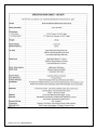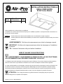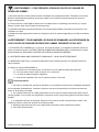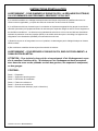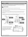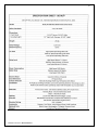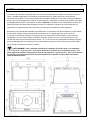
1
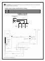
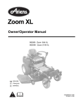
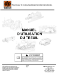
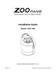
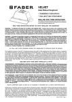
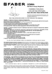
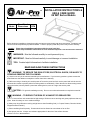
1 INSTALLATION INSTRUCTIONS & USE & CARE GUIDE 06 W/P Series Models Model Front Panel Dimensions CFM 06 W/P 16-3/4” x 26-3/4” 660 Before beginning installation, please thoroughly read and become familiar with these instructions. Installation and service must be completed by a qualified installer. Failure to properly install this product may void the warranty. Installer: Owner: Please leave Installation Instructions with the range hood liner. Please keep Installation Instructions for local electrical inspector’s use and for future reference. WARNINGS: Must be followed carefully to avoid personal injury. IMPORTANT: Must be followed carefully to avoid damage or incorrect installation. TIPS: Contain helpful information to facilitate installation. READ AND SAVE THESE INSTRUCTIONS WARNING! TO REDUCE THE RISK OF FIRE, ELECTRICAL SHOCK, OR INJURY TO PERSONS OBSERVE THE FOLLOWING: a) Use this unit only in the manner intended by the manufacturer. If you have any questions, please contact the manufacturer at the address or telephone number listed in the warranty. b) Before servicing or cleaning unit, switch power off at service panel and lock service panel and lock the service disconnection means to prevent power from being switch on accidentally. When the service disconnecting means cannot be locked, securely fasten a prominent warning device, such as a tag to the service panel. CAUTION -- For general ventilating use only. Do not use to exhaust hazardous or explosive materials and vapors. WARNING – TO REDUCE THE RISK OF A RANGE TOP GREASE FIRE: a) Never leave surface units unattended at high settings. Boilovers cause smoking and greasy spillovers that may ignite. Heat oils slowly on low or medium settings. b) Always turn hood ON when cooking at high heat or when flambéing food (i.e. Crepes Suzette, Cherries Jubilee, Peppercorn Beef Flambe’). c) Clean ventilating fans frequently. Grease should not be allowed to accumulate on fan or filter. d) Use proper pan size. Always use cookware appropriate for the size of the surface element. Installation Instructions, Revised 05/13/13 2 WARNING! TO REDUCE THE RISK OF INJURY TO PERSONS IN THE EVENT OF A RANGE TOP GREASE FIRE, OBSERVE THE FOLLOWING: a) SMOTHER FLAMES with a close-fitting lid, cookie sheet, or metal tray, then turn off the burner. BE CAREFUL TO PREVENT BURNS. If the flames do not go out immediately, EVACUATE AND CALL THE FIRE DEPARTMENT. b) NEVER PICK UP A FLAMING PAN—YOU MAY BE BURNED. c) DO NOT USE WATER, including wet dishcloths or towels. A violent steam explosion will result. d) Use an extinguisher ONLY if: 1. You know you have a Class ABC extinguisher and you already know how to operate it. 2. The fire is small and contained in the area where it started. 3. The fire department is being called. 4. You can fight the fire with your back to an exit. Recommendations: 1. Consult a licensed ventilation contractor or qualified technician for proper installation of exhaust ducting. Locate the cooking area for minimum cross drafts-away from doors and windows, when possible. 2. Ducts must be of adequate size and duct runs should be as short as possible. Where turns are necessary, keep turning radius as large and as smooth as possible. 3. The ducting must be air tight. Use a minimum of 2 sheet metal screws at every duct joint. Then, seal the duct joints with high quality duct tape. 4. Do not use this unit with any solid-state speed control device. 5. This unit must be grounded. INSTALLATION INSTRUCTIONS WARNING – TO REDUCE THE RISK OF FIRE, ELECTRIC SHOCK, OR INJURY TO PERSONS, OBSERVE THE FOLLOWING: a) Installation work and electrical wiring must be done by qualified person(s) in accordance with all applicable codes and standards, including fire-rated construction codes and standards. b) Sufficient air is needed for proper combustion and exhausting of gasses through the flue (chimney) of fuel burning equipment to prevent back drafting. Follow the heating equipment manufacturer's guidelines and safety standards such as those published by the National Fire Protection Association (NFPA) and the American Society for Heating, Refrigeration and Air Conditioning Engineers (ASHRAE) and the local code authorities. c) When cutting or drilling into wall or ceiling, do not damage electrical wiring and other hidden utilities. d) Ducted fans must always be vented to the outdoors. WARNING -- TO REDUCE THE RISK OF FIRE, USE ONLY METAL DUCTWORK. CAUTION – To reduce the risk of fire and to properly exhaust air, be sure to duct air outside – Do not vent exhaust air into spaces with in walls or ceilings or into attics, crawl spaces, or garages. CONTENTS: Part 1 - Preparation Part 2 - Range Hood Mounting Part 3 - Planning the Installation Part 4 - Securing the Liner Part 5 - Use & Care Part 6 - Electrical Connection (Copy to Electrician) Installation Instructions, Revised 05/13/13 3 PART 1 Preparation The following method is the standard installation. There may be some different cases depending on the structure where the mounting bracket is placed or the shape and mounting condition of the wood hood. In such a case, please arrange best possible way according to the condition of the place where the range hood is being installed. WARNING! • If the range hood is not installed properly, it could become detached and fall. • Ensure that the metal duct does not touch other metal/housing materials, otherwise fire or electric shock could result. This range hood is designed to discharge upward from the unit, but may vent horizontal above the unit. For vertical discharge, run duct work between the hood location and roof cap location. To get the best result, use a minimum number of transitions and elbows. Be sure to attach a roof/wall cap to avoid rain from entering the exhaust duct. Note: 8” round duct 06 W Note: 8” round duct 06 P Note: 8” round duct Note: 8” round duct The range hood unit should be mounted to a liner which has the dimensions stated in diagram. Install the liner securely after checking that the opening size of the liner is the same as the figure shown. CAUTION • The liner shape illustrated in this installation manual is only for reference. • When the liner is installed in the wooden hood, the inside of the wooden hood placed above the cooking surface must be fully covered by the metal barrier including bottom edges. Select a suitable liner and metal barrier according to the size and shape of the wooden hood and install properly. • The liner should be installed tightly. If the liner installation is not correct, the range hood unit may become detached and fall. Installation Instructions, Revised 05/13/13 4 PART 2 Range Hood Mounting CAUTION • Wear working gloves to avoid injury. Note: During installation, be careful not to touch the fan switches. If two or more switches are pushed at once, it may cause failure to the motors. Mounting procedure for 06W (Wall Mounting) Before mounting, make sure that a wood panel for mounting the range hood is fixed on the wall where the range hood is installed. Note: If no wood panel is found on the wall, be sure to prepare one referring to the figure. Place the range hood in an upright position and attach the exhaust pipe unit. Once the exhaust pipe unit is securely attached, remove the tape. Align 4 screw holes of the liner and range hood, then fix securely using the supplied screws (M5×30) and nuts. Note: Fasten all the screws and nuts evenly. Installation Instructions, Revised 05/13/13 5 Fix the supplied hanging brackets on the body firmly using 2 supplied screws (M5×10). Insert the washer-head wood screws (M5.1×45) (not supplied) into the mounting wall to align with bracket keyhole (left and right). Allow about 5mm between the screwheads and wall for mounting the range hood. Hook the temporary fixing holes of the hanging bracket on the washer-head wood screws prepared in previous step, and tighten the screws. Note: Insert tight the exhaust pipe unit into the duct. Add 2 screws (M5.1×45) to the holes under the temporary fixing holes and tighten them securely. Make the duct joint secure and airtight using non-flammable tape such as aluminum tape, etc. (not supplied) Installation Instructions, Revised 05/13/13 6 ATTENTION INSTALLERS Mounting brackets for both the wall and island installations are included. Please refer to accessories for proper mounting bracket for your installation. Wall Mount uses the two L-Shaped hanging brackets. (Discard the large rectangular mounting bracket.) Island Mount uses the large rectangular mounting bracket. (Discard the two L-Shaped hanging brackets.) Mounting procedure for 06P (Ceiling Mounting) Put 4 all thread rods (1/2” anchor bolt, not supplied) into the corner holes of the mounting bracket, and secure them using washers, spring washers, and nuts. Place the mounting bracket on the beam of the ceiling as shown. Note: The mounting bracket should be securely fastened at this point to simplify installing the range hood later. Align 4 screw holes of the liner and range hood, then fix securely using the supplied screws (M5×30) and nuts. Note: Fasten all the screws and nuts evenly. Hold up the range hood, while inserting the exhaust pipe unit into the duct, pass all 4 threaded rods through the holes of the mounting bracket. Installation Instructions, Revised 05/13/13 7 Using washers, spring washers, and double nuts, attach the range hood to all 4 threaded rods securely. Note: If taping from the outside is impossible, remove the exhaust pipe unit and insert the duct end to the range hood directly, then make inside taping on the duct end. Be sure to attach a roof/wall cap with damper in this case. ACCESSORIES 06 P 06 W Installation Instructions, Revised 05/13/13 8 Installation Instructions, Revised 05/13/13 9 PART 3 Planning the Installation The 06 W/P series ventilation modules are designed for installation inside wood hood canopies. Proper installation of the liner is directly related to the material from which the custom canopy is constructed. A qualified person must complete the installation of this unit. Plan the installation so that all minimum clearances are met or exceeded. Dimensions shown provide minimum clearances, unless otherwise specified. Important: You must provide structural framing and tight backing in the areas in which you are securing the liner inside your custom canopy. Failure to do so could distort and damage the liner and void the warranty. Given that most installations are different, a back-draft damper is not provided with this unit. Always install ventilation products with an approved wall or roof cap. Duct performance is improved by using round, smooth metal duct work instead of rectangular. If multiple elbows must be used, ensure that there is a minimum of 24” of straight duct between any two elbows. Avoid “S” or back to back configurations caused by adjacent elbows. Do not rely on duct tape alone to seal duct joints. Use sheet metal screws as required to support the duct. WARNING! For maximum ventilation performance, the bottom of the hood or liner should be 30 - 36 inches (76.2 - 91.4 cm) above the cooking surface (minimum is 24”). This would typically result in the bottom of the hood being 66 - 72 inches (167.6 - 182.9 cm) above the floor. These dimensions provide for safe and efficient operation of the hood. Always observe local building codes. Installation Instructions, Revised 05/13/13 10 PART 4 Securing the Liner MOUNTING THE LINER Note: Some hoods will have 1/8” thick wood shims installed on all four sides of the inside of the hood and some hoods will not have shims. This is due to design variations. Insert the liner into the hood with the bottom of the liner flush with the bottom of the hood. In most cases you should have a friction fit. If the liner does not have a friction fit you can use tape to temporarily hold the liner in place. With the liner in position, drill a 3/32” (0.094) diameter pilot hole 1/8” (0.125) deep in each hole location. Secure the liner to the hood using a # 8 x ½” (0.500) pan head wood screw (provided). It is highly recommended the screws be hand driven to reduce the risk of spinning the screws out in the wood. In the event you have a hood with wood shims and the fit is too tight, simply remove one or more of the shims to get a proper fit. IMPORTANT: If you remove a wood shim you must use a washer (provided) behind the head of the #8 wood screw to insure the screw will not dimple the outside surface of the hood. Note: All the mounting holes should be used to ensure adequate installation. CONNECTING TO THE VENT PIPE The 06 W/P series ventilation modules come with a metal start collar. Attach the Start Collar to the duct with at least three equally spaced screws. Also apply duct tape, preferably the metal type. Some installations, (where the outside of this portion of the duct is not accessible) will require the metal tape be applied on the inside of the duct. PART 5 Use and Care WARNING! Do NOT operate the blower / ventilator system without the filters in place, or with dirty, grease laden filters. OPERATING CONTROLS: Always activate the ventilator when using cooking appliances. For best performance, turn on the blower a few minutes before starting to cook to establish an airflow pattern within the room. Adjust the fan speed as needed. The center control adjusts the halogen lights and the right control adjusts the right blower. Left control adjusts the left blower. ENERGY SAVING TIPS: Eliminate air currents in the vicinity by shutting nearby windows and doors, turning off ceiling fans and adjusting the adjacent heating and air conditioning outlets if necessary. Place your largest pans on the rear burners whenever possible. Clean filters and grease laden surfaces often to improve efficiency. Always use lids on cookware to retain heat and moisture. Minimize the amount of liquid used to cook food. Select cookware of proper size, material and construction for the cooking task being performed. CARE & CLEANING: Proper cleaning is necessary to maintain performance and appearance, while also ensuring safe operation. The frequency of cleaning should be according to the type and amount of cooking. Best results will be achieved by cleaning soiled components as soon as possible. Filters must be cleaned regularly. Remove the filter(s) by grasping the D ring on the filter front and pulling gently. Grasp the front of the filter to remove it. To reinstall the filter, place the back edge of the filter into the back filter bracket. Lightly push the filter toward the back of the liner while pressing the front side upwards into place. The filters may be cleaned by hand washing in hot water using a mild detergent solution or by placing in an automatic dishwasher. Dry the filters before reusing. Installation Instructions, Revised 05/13/13 11 CAUTION: Most common scrubber type pads will scratch the liner. If a commercially available stainless steel cleaner is used, it is important to read the labels for chlorine compounds. Chlorine is a corrosive substance. If these compounds are present, rinse thoroughly and dry with a soft lint-free cloth. Follow polish manufacturer’s instructions. Always wipe stainless steel surfaces with the grain. Never wipe across the grain. After cleaning, reinstall the filters carefully. HALOGEN LIGHT BULBS: Blowers are designed for 50 watt MR16-GU10 Halogen Lamp. They can be purchased at most home or grocery stores, e.g., Lowe’s, Home Depot, McCoy’s, Menards or Ace True Value. PART 6 Electrical Connection IMPORTANT: Copy this page and the next page for your electrical installer. WARNING! Ensure that the power supply is disconnected before proceeding. Verify that the power supply matches the ratings found on the appliance data label before proceeding. The complete appliance must be properly grounded at all times when electrical power is applied. Do not ground the appliance with the neutral (white) house supply wire. A separate ground wire must be utilized. Failure to complete electrical connections properly may result in damaged or non-functional systems. Follow instructions carefully to ensure proper installation. It is the owner’s responsibility to ensure that a qualified person performs the electrical connection of this appliance. The electrical installation, including minimum supply wire size, must comply with the National Electric Code ANSI/NFPA 70-1990 (or latest revision) and local codes and ordinances. A copy of this standard may be obtained from: National Fire Protection Association, 1 Batterymarch Park, Quincy, Massachusetts 02269-9101 INSTRUCTIONS: A 15 to 20 amp electrical service is recommended for proper electrical supply. Before determining, calculate amp ratings based on the product label found on the 06 W/P series module. Always observe local building codes. Always use a dedicated circuit. Line load is calculated by adding the amperage of the halogen lights to the rated amperage of the ventilator. If the ventilator is rated in watts rather than amps, divide the watts by 120 and this will give you the amperage rating. CAUTION: The neutral wire (usually white) for the ventilator must connect to the same neutral wire that comes from the electrical panel to the liner. Factory Installed Variable-Speed Wiring Details Black White Green 120 volt AC from electrical panel (usually black) Neutral from electrical panel (white) Ground from elecrital panel (usually green) Wiring Diagram 01A/02A Series Models House Electrical Panel Green White (N) 120V Black (L) Liner Installation Instructions, Revised 05/13/13 BLK WHT GRN 12 Installation Instructions, Revised 05/13/13 13 WARRANTY Air-Pro™ Brand Ventilation Products What is Covered ™ VMI Inc. warrants its Air-Pro brand products to the original user, to be free of defects in materials and workmanship for three (3) years from the date of purchase. VMI Inc., at its option, will repair or replace the complete unit or any defective component without charge providing that, if requested, the product or defective component is promptly returned, prepaid to the address below. This warranty may be voided if any unauthorized service, alterations or repairs are made to the product. What is Not Covered Normal maintenance and service of any product that has been subject to misuse, negligence, accident or installation inconsistent with the recommended installation instructions Product used other than for normal in-home use or products used outside of the United States and Canada. Damage to the product caused by accident, fire, flood or other acts of God. Service calls to educate the customer in the proper use and care of the product, correct faulty installation, change fuses or reset breakers. VMI Inc. disclaims and excludes any liability for implied warranties or for incidental or consequential damages wherever permitted by law. There are no implied warranties of merchantability or fitness for a particular use or purpose. This warranty gives you specific legal rights and you may also have other rights, which vary from state to state. For Service If you need service, contact Customer Service at the address or phone number below. Provide the model number, part identification and details of the problem. Proof of purchase must be provided. VMI Inc. P.O. Box 2765 • Redmond, WA 98073 Phone: 206-835-9880 • Fax: 206-835-9876 www.vmi-inc.net Rev. 04/13 VMI, Inc. P.O. Box 2765 Redmond, WA 98073 Toll Free: 1-888-547-9880 Phone: 206-835-9880 **** Fax: 206-835-9876 Installation Instructions, Revised 05/13/13 14 INSTALLATION INSTRUCTIONS & USE & CARE GUIDE 06 W/P Series Models Model Front Panel Dimensions CFM 06 W/P 16-3/4” x 26-3/4” 660 Avant installation de commencement, complètement lisez svp et familiarisez-vous avec ces instructions. L'installation et le service doivent être accomplis par un installateur qualifié. Le manque d'installer correctement ce produit peut vider la garantie. Installaeur: Propriétaire: Veuillez laisser les instructions d'installation avec le revêtement de capot de gamme. Veuillez garder les instructions d'installation pour utiliser-et de l'inspecteur électrique local pour la future référence. AVERTISSEMENTS: Doit être suivi soigneusement pour éviter le dommage corporel. IMPORTANT: Doit être suivi soigneusement pour éviter les dommages ou l'installation incorrecte. TIP: Contenez l'information utile pour faciliter l'installation. LISEZ ET SAUVEZ CES INSTRUCTIONS AVERTISSEMENT! POUR RAMENER LE RISQUE DU FEU, LE CHOC ÉLECTRIQUE, OU LES DOMMAGES AUX PERSONNES OBSERVENT CE QUI SUIT: 1) Employez cette unité seulement de la façon prévue par le fabricant. Si vous avez n'importe quelles questions, entrez en contact avec svp le fabricant à l'adresse ou au numéro de téléphone énuméré dans la garantie. 2) Avant unité d'entretien ou de nettoyage, commutez la mise hors tension au panneau de service et fermez à clef le panneau de service et fermez à clef les moyens de débranchage de service d'empêcher la puissance d'être commutateur dessus accidentellement. Quand le service déconnectant des moyens ne peut pas être verrouillé, attachez solidement un dispositif d'avertissement en avant, tel qu'une étiquette au panneau de service. ATTENTION -- Pour l'usage de aération de général seulement. N'employez pas pour épuiser les matériaux dangereux ou explosifs et les vapeurs. Installation Instructions, Revised 05/13/13 15 AVERTISSEMENT – POUR RÉDUIRE LE RISQUE D'UN FEU DE GRAISSE DE DESSUS DE GAMME : 1) Ne laissez jamais les unités extérieures sans surveillance aux arrangements élevés. Tabagisme de cause de Boilovers et débordements graisseux qui peuvent mettre à feu. Chauffez les huiles lentement sur de bas ou moyens arrangements. 2) Tournez toujours le capot SUR en faisant cuire à la chaleur élevée ou flambéing à la nourriture (i.e. Crepes Suzette, Cerises Jubilé, boeuf Flambe de grain de poivre). 3) Ventilateurs d'aération propres fréquemment. On ne devrait pas permettre à la graisse de s'accumuler sur le ventilateur ou le filtre. 4) Employez la taille appropriée de casserole. Employez toujours le cookware approprié pour la taille de l'élément extérieur. AVERTISSEMENT! POUR RAMENER LE RISQUE DE DOMMAGES AUX PERSONNES EN CAS D'UN FEU DE GRAISSE DE DESSUS DE GAMME, OBSERVEZ CE QUI SUIT: 1) ÉTOUFFEZ LES FLAMMES avec un couvercle, une feuille de biscuit, ou un plateau à tolérances serrées en métal, puis arrêtez le brûleur. FAITES ATTENTION À EMPÊCHER DES BRÛLURES. Si les flammes ne sortent pas immédiatement, ÉVACUEZ ET APPELEZ LES CORPS DE SAPEURS-POMPIERS. 2) NE PRENEZ JAMAIS UNE CASSEROLE FLAMBOYANTE - VOUS POUVEZ ÊTRE BRÛLÉ. 3) N'EMPLOYEZ PAS L'EAU, y compris les dishclothes ou les serviettes humides. Une explosion violente de vapeur résultera. 4) Utilisez un extincteur SEULEMENT si: A. Vous savez que vous faites savoir un extincteur et à vous d'ABC de classe déjà l'actionner. B. Le feu est petit et contenu dans le secteur où il a commencé. C. Les corps de sapeurs-pompiers s'appellent. D. Vous pouvez combattre le feu avec le votre de nouveau à une sortie. Recommandations: 1. Consultez un entrepreneur autorisé de ventilation ou avez qualifié le technicien pour l'installation appropriée de la canalisation d'échappement. Localisez le secteur à cuire pour les ébauches-loin en travers minimum des portes et des fenêtres, si possible. 2. Les conduits doivent être de à taille proportionnée et les courses de conduit devraient être aussi courtes comme possible. Là où les tours sont nécessaires, continuez à tourner le rayon aussi grand et aussi lisse comme possible. 3. La canalisation doit être air fortement. Utilisez 2 vis au minimum de tôle à chaque joint de conduit. Puis, scellez les joints de conduit avec la bande de conduit de qualité. 4. N'employez pas cette unité avec aucun dispositif de commande à semi-conducteur de vitesse. 5. Cette unité doit être fondue. Installation Instructions, Revised 05/13/13 16 INSTRUCTIONS D'INSTALLATION AVERTISSEMENT – POUR RAMENER LE RISQUE DU FEU, LA DÉCHARGE ÉLECTRIQUE, OU LES DOMMAGES AUX PERSONNES, OBSERVENT CE QUI SUIT: a) Le travail d'installation et le câblage électrique doivent être faits par les personnes qualifiées selon tous les codes et normes applicables, y compris des codes de construction et des normes feu-évalués. b) Le suffisamment d'air est nécessaire pour la combustion et l'épuisement appropriés des gaz par la conduite de cheminée (cheminée) de l'équipement brûlant de carburant pour empêcher rédiger en arrière. Suivez l'équipement de chauffage manufacturer' ; les directives et les standards de sécurité de s de ce type ont édité par l'association nationale de protection contre les incendies (NFPA) et la société américaine pour le chauffage, les ingénieurs de réfrigération et de climatisation (ASHRAE) et les autorités de code local. c) Quand la coupure ou le forage dans le mur ou le plafond, n'endommagent pas le câblage électrique et d'autres utilités cachées. d) Des ventilateurs canalisés doivent toujours être exhalés à l'extérieur. AVERTISSEMENT -- POUR RÉDUIRE LE RISQUE DU FEU, EMPLOYEZ SEULEMENT LA CANALISATION EN MÉTAL. ATTENTION – Pour réduire le risque du feu et correctement à l'air d'échappement, soyez sûr de canaliser l'extérieur d'air. - N'exhalez pas l'air d'échappement dans les espaces avec dans des murs ou des plafonds ou dans des greniers, des espaces de rampement, ou des garages. CONTENU: Partie 1 - Préparation Partie 2 - Support de capot de gamme Partie 3 - Planification de l'installation Partie 4 - Fixation du revêtement Partie 5 - Guide de soin d'utiliser-et Partie 6 - Raccordement électrique (copie à l'électricien) Installation Instructions, Revised 05/13/13 17 PARTIE 1 Préparation La méthode suivante est l'installation standard. Il peut y avoir quelques différents cas selon la structure où le support est placé ou la forme et l'état de support du capot en bois. En ce cas, chargez-vous svp de la meilleure manière selon l'état de l'endroit où le capot de gamme est installé. AVERTISSEMENT! • Si le capot de gamme n'est pas installé correctement, ce pourrait devenir isolé et chute. • Assurez-vous que le conduit en métal ne touche pas d'autres matériaux en métal/logement, autrement le feu ou la décharge électrique pourrait résulter. Ce capot de gamme est conçu pour décharger vers le haut à partir de l'unité, mais peut exhaler horizontal audessus de l'unité. Pour la décharge verticale, travail couru de conduit entre l'endroit de capot et l'endroit de chapeau de toit. Pour obtenir le meilleur résultat, employez un nombre minimum de transitions et de coudes. Soyez sûr d'attacher un chapeau de toit/mur pour éviter la pluie d'entrer dans le conduit d'échappement. Note: 8” round duct 06 W 06 P Note: 8” round duct L'unité de capot de gamme devrait être montée à un revêtement qui a les dimensions indiquées dans le diagramme. Installez le revêtement solidement après avoir vérifié que la taille d'ouverture du revêtement est identique que la figure montrée. Installation Instructions, Revised 05/13/13 Note: 8” round duct Note: 8” round duct 18 AVERTISSEMENT! • La forme de revêtement illustrée en ce manuel d'installation est seulement pour la référence. • Quand le revêtement est installé dans le capot en bois, l'intérieur du capot en bois placé au-dessus de la surface à cuire doit être entièrement couvert par la barrière en métal comprenant les rebords inférieurs. Choisissez un revêtement approprié et metal la barrière selon la taille et la forme du capot en bois et l'installez correctement. • Le revêtement devrait être installé étroitement. Si l'installation de revêtement n'est pas correcte, l'unité de capot de gamme peut devenir isolée et chute. PARTIE 2 Support de capot de gamme AVERTISSEMENT! •. Gants fonctionnants d'usage pour éviter des dommages. Note: Pendant l'installation, faites attention à ne pas toucher les commutateurs de ventilateur. Si deux commutateurs ou plus sont poussés immédiatement, il peut causer échec aux moteurs. Procédé de support pour 06W (support de mur) Avant le montage, assurez-vous qu'un panneau en bois pour monter le capot de gamme est fixe sur le mur où le capot de gamme est installé. Note: Si aucun panneau en bois n'est trouvé sur le mur, soyez sûr de préparer on se rapportant à la figure. Placez le capot de gamme dans une position droite et attachez l'unité de pot d'échappement. Une fois que l'unité de pot d'échappement est solidement jointe, enlevez la bande. Installation Instructions, Revised 05/13/13 19 Alignez 4 trous de vis du revêtement et étendez-vous capot, puis les fixez solidement utilisant les vis fournies (M5×30) et écrous. . Note: Attachez tous les vis et écrous également. Fixez les parenthèses accrochantes fournies sur le corps fermement utilisant 2 fournis vis (M5×10). Insérez les vis en bois de rondelle-tête (M5.1×45) (non fourni) dans le mur de support pour aligner avec le trou de la serrure de parenthèse (left and right). Permettez environ 5mm entre les têtes de vis et le mur pour monter le capot de gamme. Accrochez les trous de fixation provisoires de la parenthèse accrochante des vis en bois de rondelle-tête prepares dans l'étape précédente, et serrez les vis. Note: Insérez fortement l'unité de pot d'échappement dans le conduit. Installation Instructions, Revised 05/13/13 20 Ajoutez 2 vis (M5.1×45) aux trous sous les trous de fixation provisoires et serrez-les solidement. Rendez le joint de conduit bloqué et hermétique utilisant la bande inflammable telle que la bande en aluminium, etc. (non fournis). INSTALLATEURS D'ATTENTION Les supports pour les installations de mur et d'île sont inclus. Veuillez se référer aux accessoires pour le support approprié pour votre installation. Le bâti de mur utilise les deux parenthèses accrochantes en forme de L. (Jetez le grand support rectangulaire.) Le bâti d'île emploie le grand support rectangulaire. (Jetez les deux parenthèses accrochantes en forme de L.) Procédé de support pour 06P (support de plafond) Mettez 4 toutes les tiges de fil (boulon d'anchrage de pouce de 1/2, non fourni) dans les trous faisants le coin du support, et fixez-les utilisant des rondelles, des rondelles à ressort, et des écrous. Placez le support sur le faisceau du plafond comme montré. Note: Le support devrait être solidement attaché en ce moment pour simplifier installer le capot de gamme plus tard. Installation Instructions, Revised 05/13/13 21 Alignez 4 trous de vis du revêtement et étendez-vous capot, puis les fixez solidement utilisant les vis fournies (M5×30) et écrous. Note: Attachez tous les vis et écrous également. Supportez le capot de gamme, tout en insérant l'unité de pot d'échappement dans le conduit, passez chacune des 4 tiges filetées par les trous du support. Utilisant des rondelles, les rondelles à ressort, et les doubles écrous, attachnt le capot de gamme à chacune des 4 tiges filetées solidement. Note: Si le taping de l'extérieur est impossible, enlevez l'unité de pot d'échappement et insérez l'extrémité de conduit au capot de gamme directement, alors faites le taping d'intérieur sur l'extrémité de conduit. Soyez sûr d'attacher un chapeau de toit/mur avec l'amortisseur dans ce cas-ci. Installation Instructions, Revised 05/13/13 22 ACCESSOIRES 06 P 06 W Installation Instructions, Revised 05/13/13 23 Installation Instructions, Revised 05/13/13 24 PARTIE 3 Planification de l'installation Les modules de ventilation de 06 W/P séries sont conçus pour l'installation à l'intérieur des verrières en bois de capot. L'installation appropriée du revêtement est directement liée au matériel duquel la verrière faite sur commande est construite. Une personne qualifiée doit accomplir l'installation de cette unité. Prévoyez l'installation de sorte que tous les dégagements minimum soient rencontrés ou dépassés. Les dimensions montrées fournissent des dégagements minimum, sauf indication contraire. Important: Vous devez fournir l'encadrement structural et le support serré dans les secteurs dans lesquels vous fixez le revêtement à l'intérieur de votre verrière faite sur commande. Le manque de faire ainsi a pu tordre et endommager le revêtement et vider la garantie. Étant donné que la plupart des installations sont différentes, un amortisseur d'en arrière-ébauche n'est pas équipé de cette unité. Installez toujours les produits de ventilation avec un chapeau approuvé de mur ou de toit. L'exécution de conduit est améliorée en employant en rond, travail sans heurt de conduit en métal au lieu de rectangulaire. Si des coudes multiples doivent être employés, assurez-vous qu'il y a un minimum de 24 » du conduit droit entre deux coudes quelconques. Évitez « S » ou de nouveau aux configurations arrières provoquées par les coudes adjacents. Ne comptez pas sur seule bande de conduit pour sceller des joints de conduit. Utilisez les vis de tôle au besoin pour soutenir le conduit. AVERTISSEMENT! Pour l'exécution maximum de ventilation, le fond du capot ou le revêtement devrait être de 30 - 36 pouces (76.2 - 91.4 cm) au-dessus de la surface à cuire (le minimum est 24”). Ceci aurait typiquement comme conséquence le fond du capot étant 66 - 72 pouces (167.6 - 182.9 cm) au-dessus du plancher. Ces dimensions prévoient le fonctionnement sûr et efficace du capot. Observez toujours codes du bâtiment locaux. Installation Instructions, Revised 05/13/13 25 PARTIE 4 Fixation du revêtement MONTAGE DU REVÊTEMENT Note : Quelques capots auront 1/8" de cales en bois épaisses installées de chacun des quatre côtés de l'intérieur du capot et quelques capots n'auront pas des cales. C'est dû aux variations de conception. Insérez le revêtement dans le capot avec le fond de l'éclat de revêtement avec le fond du capot. Dans la plupart des cas vous devriez faire adapter un frottement. Si le revêtement n'a pas un frottement adapté vous pouvez utiliser la bande pour tenir temporairement le revêtement en place. Avec le revêtement en position, forez un 3/32” (0.094) du trou pilote 1/8” de diamètre (0.125) profondément dans chaque endroit de trou. Fixez le revêtement au capot utilisant vis en bois principale de casserole de ½” de #8 X une 0.500) (fournie). Elle est fortement - a recommandé les vis soit main conduite pour réduire le risque de tourner les vis dehors dans le bois. En cas vous avez un capot avec les cales en bois et l'ajustement est trop serré, enlèvent simplement un ou plusieurs des cales pour obtenir un ajustement approprié. IMPORTANT : Si vous enlevez une cale en bois vous devez employer une rondelle (fournie) derrière la tête de la vis #8 en bois pour s'assurer que la vis n'embrévera pas la surface extérieure du capot. Note : Tous les trous de montage devraient être employés pour assurer à installation proportionnée. SE RELIER DANS LA PIPE DE PASSAGE Les modules de ventilation de 06 W/P séries viennent avec un collier de début en métal. Attachez le collier de début au conduit avec au moins trois vis équidistantes. Appliquez également la bande de conduit, de préférence le type en métal. Quelques installations, (où l'extérieur de cette partie du conduit n'est pas accessible) exigeront la bande en métal soient appliquées sur l'intérieur du conduit. PARTIE 5 Guide de soin d'utiliser-et AVERTISSEMENT! N'actionnez pas le système de ventilateur sans filtres en place, ou avec sale, les filtres chargés par graisse. COMMANDES D'OPÉRATION: Activez toujours le ventilateur à l'aide des appareils de cuisson. Pour la meilleure exécution, allumez le ventilateur quelques minutes avant de commencer à faire cuire pour établir un modèle de flux d'air dans la salle. Ajustez la vitesse de l'hélice comme nécessaire. La commande centrale ajuste les lumières d'halogène et la bonne commande ajuste le ventilateur droit. La commande gauche ajuste le ventilateur gauche. TIP D'ÉCONOMIE D'ÉNERGIE: Éliminez les courants d'air à proximité en fermant les fenêtres et les portes voisines, en arrêtant des ventilateurs de plafond et en ajustant les sorties adjacentes de chauffage et de climatisation au besoin. Placez vos plus grandes casseroles sur les brûleurs arrière autant que possible. Nettoyez les filtres et graissez les surfaces chargées souvent pour améliorer l'efficacité. Utilisez toujours les couvercles sur le cookware pour maintenir la chaleur et l'humidité. Réduisez au minimum la quantité de liquide employée pour faire cuire la nourriture. Choisissez le cookware de la taille, du matériel et de la construction appropriés pour la tâche à cuire étant exécutée. Installation Instructions, Revised 05/13/13 26 SOIN ET NETTOYAGE: Le nettoyage approprié est nécessaire pour maintenir l'exécution et l'aspect, tout en également assurant l'exploitation sûre. La fréquence du nettoyage devrait être selon le type et la quantité de cuisson. Les meilleurs résultats seront réalisés en nettoyant les composants salis aussitôt que possible. Des filtres doivent être nettoyés régulièrement. Enlevez les filtres en saisissant le clip D sur l'avant de filtre et en tirant doucement. Saisissez l'avant du filtre pour l'enlever. Pour réinstaller le filtre, placez le bord arrière du filtre dans la parenthèse arrière de filtre. Poussez légèrement le filtre vers le dos du revêtement tout en pressant la partie antérieure vers le haut dans l'endroit. Les filtres peuvent être à la main lavage nettoyé en eau chaude utilisant une solution détersive douce ou par le placement dans un lave-vaisselle automatique. Séchez les filtres avant la réutilisation. ATTENTION: La plupart de type commun garnitures d'épurateur rayera le revêtement. Si un décapant disponible dans le commerce d'acier inoxydable est employé, il est important de lire les étiquettes pour des composés chlorés. Le chlore est une substance corrosive. Si ces composés sont présents, rincez complètement et séchez avec un chiffon non pelucheux mou. Suivez les instructions du fabricant polonais. Essuyez toujours les surfaces d'acier inoxydable avec le grain. N'essuyez jamais à travers le grain. Après nettoyage, réinstallez les filtres soigneusement. AMPOULES D'HALOGÈNE: Des ventilateurs sont conçus pour 50 watt MR16-GU10 Halogen Lamp. Ils peuvent être tout au plus maison ou épiceries achetée, par exemple, Lowe, Home Depot, McCoy, Menards ou Ace la valeur vraie. PARTIE 6 Raccordement électrique (copie à l'électricien) IMPORTANT : Copier cette page et la prochaine page pour votre programme d'installation électrique. AVERTISSEMENT! Assurez-vous que l'alimentation d'énergie est disconnected avant la marche à suivre. Vérifiez que l'alimentation d'énergie assortit les estimations trouvées sur l'étiquette de données d'appareils avant la marche à suivre. L'appareil complet doit être correctement fondu à tout moment quand le courant électrique est appliqué. Ne rectifiez pas l'appareil avec le fil (blanc) neutre d'approvisionnement de maison. Un fil de masse séparé doit être utilisé. Le manque d'accomplir les raccordements électriques correctement peut avoir comme conséquence les systèmes endommagés ou non fonctionnels. Suivez les instructions d'assurer soigneusement l'installation appropriée. Il est de la responsabilité du propriétaire de s'assurer qu'une personne qualifiée effectue le raccordement électrique de cet appareil. L'installation électrique, y compris la taille minimum de fil d'approvisionnement, doit être conforme au code électrique national ANSI/NFPA 70-1990 (ou dernière révision) et des codes locaux et des ordonnances. Une copie de cette norme peut être obtenue à partir : Association nationale de protection contre les incendies, 1 parc de Batterymarch, Quincy, le Massachusetts 02269-9101. INSTRUCTIONS: Un service électrique de 15 à 20 ampères est recommandé pour l'alimentation électrique appropriée. Avant la détermination, calculez les estimations d'ampère basées sur l'étiquette de produit trouvée sur le module de 06 W/P séries. Observez toujours codes du bâtiment locaux. Utilisez toujours un circuit consacré. La ligne charge est calculée en ajoutant l'ampérage des lumières d'halogène à l'ampérage évalué du ventilateur. Si le ventilateur est évalué en watts plutôt que des ampères, divisez les watts par 120 et ceci te donnera l'estimation d'ampérage. Installation Instructions, Revised 05/13/13 27 ATTENTION: Le fil neutre (habituellement blanc) pour le ventilateur doit se relier au même fil neutre qui vient du panneau électrique au revêtement. Installé en usine à régime variable détails de câblage Noir Blanc Vert 120 Volts AC de panneau électrique (généralement le noir) Position neutre du panneau électrique (blanc) La masse de panneau elecrital (généralement en vert) SCHÉMA de CẤBLAGE 06 W/P Series Models House Electrical Panel Green White (N) 120V Black (L) Liner Installation Instructions, Revised 05/13/13 BLK WHT GRN 28 WARRANTY Air-Pro™ Brand Ventilation Products What is Covered ™ VMI Inc. warrants its Air-Pro brand products to the original user, to be free of defects in materials and workmanship for three (3) years from the date of purchase. VMI Inc., at its option, will repair or replace the complete unit or any defective component without charge providing that, if requested, the product or defective component is promptly returned, prepaid to the address below. This warranty may be voided if any unauthorized service, alterations or repairs are made to the product. What is Not Covered Normal maintenance and service of any product that has been subject to misuse, negligence, accident or installation inconsistent with the recommended installation instructions Product used other than for normal in-home use or products used outside of the United States and Canada. Damage to the product caused by accident, fire, flood or other acts of God. Service calls to educate the customer in the proper use and care of the product, correct faulty installation, change fuses or reset breakers. VMI Inc. disclaims and excludes any liability for implied warranties or for incidental or consequential damages wherever permitted by law. There are no implied warranties of merchantability or fitness for a particular use or purpose. This warranty gives you specific legal rights and you may also have other rights, which vary from state to state. For Service If you need service, contact Customer Service at the address or phone number below. Provide the model number, part identification and details of the problem. Proof of purchase must be provided. VMI Inc. P.O. Box 2765 • Redmond, WA 98073 Phone: 206-835-9880 • Fax: 206-835-9876 www.vmi-inc.net Rev. 04/13 VMI, Inc. P.O. Box 2765 Redmond, WA 98073 Toll Free: 1-888-547-9880 Phone: 206-835-9880 **** Fax: 206-835-9876 Installation Instructions, Revised 05/13/13