1
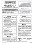
OWNER’S
MANUAL
DESIGN CERTIFIED
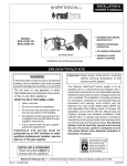
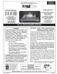
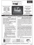
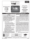
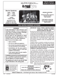
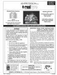
Burner Systems:
to
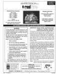
Vented Decorative Appliance
ANSI Z21.60-2012
CSA 2.26-2012
G22-GL-18(G)-01(M)(P)
G22-GL-24(G)-01(M)(P)
G22-GL-30(G)-01(M)(P)
FOR INSTALLATION IN
SOLID-FUEL BURNING
FIREPLACES*
FOR USE WITH
FYRE GLASS / FYRE GEMS
18"
10.0 lbs
24"
12.5 lbs
30"
15.0 lbs
FOR INDOOR OR
OUTDOOR USE
G22-GL VENTED BURNER SYSTEMS
IMPORTANT: READ THESE INSTRUCTIONS
CAREFULLY BEFORE STARTING
INSTALLATION OF THE UNIT.
WARNING
If the information in this manual is not
followed exactly, a fire or explosion
may result, causing property damage,
personal injury, or loss of life.
The Real-Fyre burner system is to be installed only in
a solid-fuel burning fireplace with a working flue and
constructed of noncombustible material.The installation,
including provisions for combustion and ventilation air
must conform with the National Fuel Gas Code, ANSI
Z223.1/NFPA 54, or the CSA B149.1, Natural Gas
and Propane Installation Code, and applicable local
building codes.
A damper clamp is included to maintain the minimum
permanent vent opening and to prevent full closure
of the damper blade. The chimney damper MUST
be fully opened when burning the unit. The unit is
designed to burn with yellow flames; thus adequate
ventilation is absolutely necessary.
To comply with certification, listings, and building
code acceptances, and for safe operation and proper
performance of this burner system, use ONLY Peterson
parts and accessories. Use of other controls, parts,
and accessories that are not designed for use with
Real-Fyre burner systems is prohibited and will void
all warranties, certifications, listings, and building code
approvals, and may cause property damage, personal
injury, or loss of life.
*Note: Solid-fuels shall not be burned in a fireplace
where a decorative appliance is installed.
Do not store or use gasoline or other
flammable vapors and liquids in the
vicinity of this or any other appliance.
WHAT TO DO IF YOU SMELL GAS:
• Open a window.
• Do not try to light any appliance.
• Do not touch any electrical switch; do
not use any phone in the building.
• Immediately call the gas supplier
from a neighbor’s phone. Follow gas
supplier’s instructions.
• If you cannot reach the gas supplier,
call the fire department.
Installation and service must be performed
by a qualified professional installer,
service agency, or the gas supplier.
This appliance is only for use with the type
of gas indicated on the rating plate.
INSTALLER:
Leave this manual with the appliance.
CONSUMER:
Retain this manual for future reference.
12-021
Robert H. Peterson Co. • 14724 East Proctor Avenue • City of Industry, CA 91746
REV 1 - 1403191435
1
L-A2-347
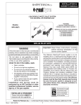
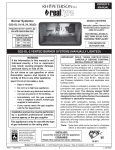
MANUEL DU
PROPRIÉTAIRE
CONCEPTION CERTIFIÉE
Systèmes De Brûleur:
à
Vented Decorative Appliance
ANSI Z21.60-2012
CSA 2.26-2012
G22-GL-18(G)-01(M)(P)
G22-GL-24(G)-01(M)(P)
G22-GL-30(G)-01(M)(P)
POUR L'INSTALLATION DANS
LE COMBUSTIBLE SOLIDE DE
BRÛLANT FIREPLACES*
POUR L'USAGE AVEC
FYRE GLASS / FYRE GEMS
18"
10.0 lbs
24"
12.5 lbs
30"
15.0 lbs
POUR L'USAGE D'INTÉRIEUR
OU EXTÉRIEUR
G22-GL SYSTÈMES EXHALÉS DE BRÛLEUR
IMPORTANT: L I S E Z C E S I N S T RU C T I O N S
SOIGNEUSEMENT AVANT DE
COMMENCER L'INSTALLATION DE
L'UNITÉ.
Le Vrai-Fyre système de brûleur doit être installée
seulement dans une cheminée brûlante de combustible
solide avec une conduite de cheminée fonctionnante
et être construit avec du matériel non-combustible.
L'installation, y compris des dispositions pour l'air de
combustion et de ventilation doit se conformer au code
national de gaz de carburant, la norme ANSI Z223.1/
NFPA 54, ou le CSA B149.1, code d'installation de gaz
naturel et de propane, et codes du bâtiment locaux
applicables.
Une bride plus humide est incluse pour maintenir
l’ouverture permanente minimum de passage et pour
empêcher la pleine fermeture de la lame plus humide.
L'amortisseur de cheminée DOIT être entièrement
ouvert en brûlant l'unité. L'unité est conçue pour
brûler avec les flammes jaunes; ainsi à ventilation
proportionnée est absolument nécessaire.
Pour se conformer à la certification, les listes, et
les acceptations de codes du bâtiment, et pour
l'exploitation sûre et l'exécution appropriée de ce
système de brûleur, utilisent SEULEMENT des pièces
et des accessoires de Peterson. L'utilisation d'autres
commandes, pièces, et accessoires qui ne sont pas
conçus pour l'usage avec de Real-Fyre systèmes de
brûleur est interdite et videra toutes les garanties,
certifications, listes, et approbations de codes du
bâtiment, et peut causer des dégats matériels, le
dommage corporel, ou des pertes humaines.
*Note: des Plein-carburants ne seront pas brûlés
dans une cheminée où un appareil décoratif
est installé.
AVERTISSEMENT
Si l’information en ce manuel n’est pas suivie
exactement, une incendie ou une explosion
peut résulter, entraînant des dégats
matériels, des blessures, ou la perte de la vie.
Ne stockez pas ou n’employez pas l’essence
ou d’autres vapeurs et liquides inflammables
à proximité de ceci ou d’aucun autre appareil.
CE QUI À FAIRE SI VOUS SENTEZ LE GAZ:
• Ouvrez une fenêtre.
• N’essayez pas de n’allumer aucun appareil.
• Ne touchez aucun commutateur
électrique; n’utilisez aucun téléphone
dans le bâtiment.
• Appelez immédiatement le fournisseur
de gaz du téléphone du voisin. Suivez les
instructions du fournisseur de gaz.
• Si vous ne pouvez pas atteindre le
fo u r n i s s e u r d e g a z , a p p e l e z l e
département de feu.
L’installation et le service doivent être assurés
par un installateur qualifié et professionnel,
l’agence de service, ou le fournisseur de gaz.
Cet appareil sert seulement avec le type de
gaz indiqué de la plaque de contrôle.
INSTALLATEUR :
Laissez ce manuel avec l'appareil.
CONSOMMATEUR:
Maintenez ce manuel pour la future référence.
12-021
Robert H. Peterson Co. • 14724 East Proctor Avenue • City of Industry, CA 91746
REV 1 - 1403191435
2
L-A2-347
TABLE OF CONTENTS
5
6
6
7
8
9
10
11
11
11
12
12
12
12
13
13
13
15
15
17
17
17
19
19
19
20
21
23
24
IMPORTANT PRE-INSTALLATION AND FIREPLACE SAFETY INFORMATION
SPECIFICATIONS
DAMPER CLAMP INSTRUCTIONS
BURNER PARTS LIST - REMOTE MODEL
BURNER PARTS LIST - MANUAL MODEL
BURNER INSTALLATION
REMOTE SYSTEM (if equipped)
DECORATIVE MEDIA PLACEMENT
GLASS/GEMS PLACEMENT (purchased separately)
DECORATIVE MEDIA ON FIREPLACE FLOOR (optional)
INSTALLING/REPLACING BATTERIES
REMOTE TRANSMITTER BATTERY
REMOTE RECEIVER BATTERIES AND/OR REMOTE RECEIVER BOX BATTERIES
SWITCH BOX BATTERIES
LIGHTING INSTRUCTIONS - REMOTE MODEL
MANUAL LIGHTING
REMOTE LIGHTING
PILOT APPEARANCE
SHUTTING DOWN
LIGHTING INSTRUCTIONS - MANUAL MODEL
PILOT APPEARANCE
SHUTTING DOWN
CLEANING AND SERVICING SAFETY INFORMATION
FLAME DESCRIPTION
TO CLEAN THE BURNER SYSTEM
NOTES PAGE
TROUBLESHOOTING
ELECTRONIC PILOT TROUBLESHOOTING
WARRANTY
REV 1 - 1403191435
3
L-A2-347
L'INFORMATION DE SÛRETÉ IMPORTANTE DE PRÉINSTALLATION ET DE CHEMINÉE
ATTENTION:
L'installation et la réparation doivent être faites par un NFI certifié ou tout autre installateur professionnel
qualifié.
Installateur:
Lisez soigneusement ces instructions avant d'installer ce système de brûleur à gaz. Soyez sûr que vous comprenez
tous les mesures de sécurité et avertissements contenus en ce manuel.
A. Cet appareil est conçu comme appareil occupé. Les adultes doivent être présent quand cet appareil à gaz fonctionne. Ne
laissez pas ce burning d'unité si sans surveillance ou tandis que n'importe qui dort.
B. Cet appareil sert seulement avec le type de gaz indiqué de la plaque de contrôle. Cet appareil n'est pas CONVERTIBLE de
CHAMP pour l'usage avec d'autres gaz.
C. FAITES ATTENTION: Sinon installé, entretenu, et utilisé correctement par ces instructions, ce produit peut causer
le dommage corporel, les dégats matériels, ou les pertes humaines sérieux.
D. AVERTISSEMENT: Avant l'installation dans une cheminée plein-carburant-brûlante, la conduite de cheminée, l'amortisseur, et
le foyer de cheminée doivent ÊTRE COMPLÈTEMENT NETTOYÉS de la suie, de la créosote, des cendres, et de la peinture
lâche, et doivent être inspectés par un décapant qualifié de cheminée. Quelques cheminées plus anciennes peuvent ont
besoin de réparation avant d'installer cet appareil.
E. VÉRIFIEZ LE TYPE de GAZ (normal ou propane) : La fourniture de gaz doit être identique qu'indiquée de votre plaque de
contrôle de système de brûleur. Si la fourniture de gaz est différente, N'INSTALLEZ PAS. Contactez votre revendeur pour
l'aide immédiate.
F.
Gardez le domaine du clair réglé de notation de gaz et libérez des matériaux combustibles, l'essence, et d'autres vapeurs
et liquides inflammables.
G. LA PRESSION DE GAZ INSUFFISANTE GARDERA LE PILOTE DU FONCTIONNEMENT CORRECTEMENT (SI ÉQUIPÉ).
N'EMPLOYEZ PAS SI LA PRESSION DE GAZ EST INFÉRIEURE À LA CONDITION MINIMUM.
H. L'admission minimum gaz-fournissent la pression aux fins de l'ajustement d'entrée est 5" ; colonne d'eau (w.c.) sur le gaz
naturel et le 11" ; w.c. sur le gaz de propane. La pression de gaz insuffisante affectera l'opération appropriée du pilote (si
équipé). N'installez pas cet appareil à gaz si la pression minimum n'est pas disponible. L'admission maximum gaz-fournissent
la pression est 10.5" ; w.c. sur le gaz naturel et le 13" ; w.c. sur le gaz de propane. La source de propane doit être réglée. (Ne
pas connecter cet appareil directement à un réservoir de gaz propane non -. Cela peut provoquer une explosion)
Ne pas brancher cet appareil à une bouteille de gaz propane portable.
I.
Le système sifflant de gaz doit être classé pour fournir la pression d'admission minimum au débit maximum (BTU/
hr). La perte de pression anormale se produira si la pipe est trop petite, ou la course est trop longue. La pipe de fourniture de
gaz doit être 1/2" ; diamètre intérieur minimum. Si la ligne de gaz est plus longue que 20' ; une ligne de plus grand diamètre
peut être nécessaire. Reportez-vous aux directives NFPA 54 pour plus de détails.
J.
Les estimations d'entrée montrées en Btu par heure sont pour des altitudes jusqu'à 2.000 pi. Pour des altitudes au-dessus de
2.000 pi, référez-vous au code national de gaz de carburant ou entrez en contact avec le fabricant avant d'installer ce produit.
K. Cet appareil à gaz et son clapet à gaz principal doivent être disconnected du gaz-fournissent le système sifflant pendant tout
vérificateur de pression de ce système aux pressions d'essai au-dessus de 1/2 psig.
L.
Cet appareil à gaz doit être isolé dans gaz-fournissent le système sifflant en fermant le robinet d'isolement d'équipement relié
au gaz-fournissent la ligne pendant tout vérificateur de pression du gaz-fournissent le système sifflant aux pressions d'essai
égales à ou moins d'à 1/2 psig.
M. N'employez pas cet appareil si n'importe quelle partie a été sous-marine. Appelez immédiatement un technicien qualifié de
service pour inspecter l'appareil et pour remplacer n'importe quelle partie du système de contrôle et de n'importe quelle
commande de gaz qui a été sous-marine.
N. Una pantalla de la chimenea debe ser en el lugar cuando el sistema está quemando. Las provisiones para el aire de
combustión adecuado deben ser mantenidas. A menos que otras provisiones para el aire de combustión se proporcionen, la
pantalla tendrá una abertura para la introducción de aire de combustión. El aire de combustión es adecuado cuando todas
las llamas se encrespan en la chimenea y lejos de la pantalla. Cuando se utiliza un recinto de cristal de la chimenea
(puerta), deje las puertas completamente abiertas cuando el sistema es en funcionamiento.
O. Cet appareil peut être installé dans un marché des accessoires, maison (mobile) de manière permanente située et manufacturée,
où non interdit par des codes locaux. L'installation des appareils a conçu pour la maison manufacturée (États-Unis seulement)
ou installation de caravane résidentielle doit se conformer au CAN/CSA standard Z240 MH, logement mobile, au Canada, ou à
la construction et au standard de sécurité à la maison manufacturés, intitulent 24 CFR, la partie 3280, aux Etats-Unis, ou quand
une telle norme ne s'applique pas, à ANSI/NCSBCS A225.1/NFPA 501A, installations à la maison manufacturées standard.
P. LE VERRE OU LES GEMMES DE PETERSON (VRAI FYRE) SONT LES SEULS MÉDIAS CERTIFIÉS POUR ÊTRE
EMPLOYÉ DANS CE BRÛLEUR. N'EMPLOYEZ AUCUN AUTRE MILIEU. L'installation correcte du verre/gemmes et le
placement et l'installation appropriés du brûleur, sont impérative à l'exploitation sûre de votre appareil. Les problèmes se
poseront si tous les articles ne sont pas correctement installés.
Q. La quantité correcte de verre/de gemmes doit être employée sur votre système de brûleur pour qu'elle fonctionne correctement. Vous pouvez employer le verre/gemmes additionnels, ou des granules de lave pour couvrir le plancher de la cheminée. Veuillez lire la section DÉCORATIVE entière de PLACEMENT de MÉDIAS pour des détails.
4
IMPORTANT PRE-INSTALLATION AND FIREPLACE SAFETY INFORMATION
CAUTION: Installation and repair must be done by an NFI Certified or other qualified professional
installer.
Installer:
Carefully read these instructions before installing this gas burner system. Be sure you understand
all safety precautions and warnings contained in this manual.
A. This appliance is designed as an attended appliance. Adults must be present when this gas appliance is operating.
Do not leave this unit burning when unattended or while anyone is sleeping.
B. This appliance is only for use with the type of gas indicated on the rating plate. This appliance is NOT FIELD
CONVERTIBLE for use with other gasses.
C. BE CAREFUL: If not installed, serviced, and used correctly per these instructions, this product can cause
serious personal injury, property damage, or loss of life.
D. WARNING: Before installing in a solid-fuel-burning fireplace, the chimney flue, damper, and firebox must be
thoroughly CLEANED of soot, creosote, ashes, and loose paint, and must be inspected by a qualified chimney
cleaner. Some older fireplaces may need repair prior to installing this appliance.
E. CHECK GAS TYPE (natural or L.P.): The gas supply must be the same as stated on your burner system rating plate.
If gas supply is different, DO NOT INSTALL. Contact your dealer for immediate assistance.
F. Keep the area of the gas burner system clear and free from combustible materials, gasoline, and other flammable
vapors and liquids.
G. INSUFFICIENT GAS PRESSURE WILL KEEP THE PILOT (IF EQUIPPED) FROM OPERATING PROPERLY. DO NOT
USE IF GAS PRESSURE IS LOWER THAN THE MINIMUM REQUIREMENT.
H. The minimum inlet gas-supply pressure for purposes of input adjustment is 5" water column (w.c.) on natural gas
and 11" w.c. on L.P. gas. Insufficient gas pressure will affect proper operation of the pilot (if equipped). Do not install
this gas appliance if minimum pressure is not available. The maximum inlet gas-supply pressure is 10.5" w.c. on
natural gas and 13" w.c. on L.P. gas. The L.P. source must be regulated. (Do not connect this appliance directly to
an unregulated L.P. gas tank - this can cause an explosion.) Do not connect this appliance to a portable L.P.
gas cylinder.
I. The gas piping system must be sized to provide minimum inlet pressure at the maximum flow rate (BTU/hr).
Undue pressure loss will occur if the pipe is too small, or the run is too long. Gas supply pipe must be 1/2" minimum
interior diameter. If the gas line is longer than 20', a larger diameter line may be necessary. Refer to the NFPA 54
guidelines for further details.
J. Input ratings shown in BTU per hour are for elevations up to 2,000 ft. For elevations above 2,000 ft., refer to the National
Fuel Gas Code or contact manufacturer before installing this product.
K. This gas appliance and its main gas valve must be disconnected from the gas-supply piping system during any pressure
testing of that system at test pressures in excess of 1/2 psig.
L. This gas appliance must be isolated from the gas-supply piping system by closing the equipment shutoff valve connected
to the gas-supply line during any pressure testing of the gas-supply piping system at test pressures equal to or less
than 1/2 psig.
M. Do not use this appliance if any part has been underwater. Immediately call a qualified service technician to inspect the
appliance and to replace any part of the control system and any gas control that has been underwater.
N. A fireplace screen must be in place when the system is burning. Provisions for adequate combustion air must be
maintained. Unless other provisions for combustion air are provided, the screen shall have an opening(s) for introduction
of combustion air. Combustion air is adequate when all flames curl into the fireplace and away from the screen. When
a glass fireplace enclosure (door) is used, leave the doors fully open when the system is in operation.
O. This appliance may be installed in an aftermarket, permanently located, manufactured (mobile) home, where not
prohibited by local codes. Installation of appliances designed for manufactured home (U.S. only) or mobile home
installation must conform with the Standard CAN/CSA Z240 MH, Mobile Housing, in Canada, or with the Manufactured
Home Construction and Safety Standard, Title 24 CFR, Part 3280, in the United States, or when such a standard is not
applicable, ANSI/NCSBCS A225.1/NFPA 501A, Manufactured Home Installations Standard.
P. PETERSON (REAL FYRE) GLASS OR GEMS ARE THE ONLY MEDIA CERTIFIED TO BE USED IN THIS BURNER.
DO NOT USE ANY OTHER MEDIA. Correct installation of the glass/gems and proper placement and installation of the
burner assembly, are imperative to safe operation of your appliance. Problems WILL occur if all items are not properly
installed.
Q. The correct amount of glass/gems must be used on your burner system for it to operate properly. You may use
additional glass/gems, or lava granules to cover the floor of the fireplace. Please read the entire DECORATIVE MEDIA
PLACEMENT section for details.
5
SPECIFICATIONS
Real-Fyre gas burner systems must be installed only in a wood burning fireplace with the minimum firebox
dimensions and venting requirements met (see table on this page). This appliance is designed to burn with
yellow flames; adequate ventilation is absolutely necessary.
Minimum Fireplace Size
Burner
Model
Width
Depth
Height
Natural Gas
Propane Gas
19"
13"
15"
40k
28k
33"
25"
13"
15"
55k
40k
39"
32"
13"
15"
65k
50k
Front
Rear
G22-GL-18(G)-01(M)(P)
27"
G22-GL-24(G)-01(M)(P)
G22-GL-30(G)-01(M)(P)
Note:
BTU Rating
Rear width is at corresponding depth.
Minimum permanent free opening area of chimney damper for venting (sq. in.)
For factory-built fireplaces *
Chimney height
18"
24"
30"
15'
18
24
30
20'
15
21
25
30'
12
16
19
* For masonry-built fireplaces, add 5 sq. in. to amount shown
Note: The minimum chimney height from hearth to top of chimney is 15'.
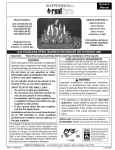
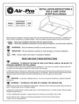
PILOT
S
CONTROL
MODULE
BATTERY-D BATTERY BOX
WIRE HARNESS
WIRE HARNESS
INLET
VALVE
REMOTE
SYSTEM
AA-BATTERIIES (4)
OUTLET
GREEN
BLUE
ORANGE
WIRES, OPTIONAL
WALL SWITCH
(Remote model shown)
Wiring Diagram
Fig. 6-1
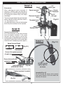
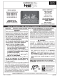
DAMPER CLAMP INSTRUCTIONS
The damper clamp with hex bolt (Fig. 6-2) is provided as a means to
prevent full closure of the damper blade. The clamp is easily attached to
most damper blades with pliers or a wrench, and must be permanently
installed.The clamp is designed to prevent accidental closure of the damper
when installed as illustrated (Fig. 6-3 and Fig. 6-4). Should the clamp not
fit, or fail to provide the permanent vent opening listed in the table found
above, have a permanent stop installed, remove
the damper blade, or have the damper cut to Set screw
provide the minimum permanent opening required.
Note: These are minimum damper opening
specifications. The damper must be
completely opened when operating
this gas appliance to achieve the best
ventilation possible.
Damper clamp
Fig. 6-2
6
Open
Closed
Fig. 6-3
Fig. 6-4
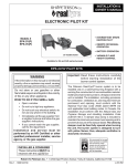
BURNER PARTS LIST - REMOTE MODEL
Note: Photos not to scale
2
Pilot assembly
1
6
24" Model shown
4
5
9
10
8
3
Bottom view
7
Control valve, rear view
Replacement parts can be ordered
from your local Real-Fyre dealer.
18" model
Item
24" model
30" model
Description
Part No.
Qty.
Part No.
Qty.
Part No.
Qty.
1.
Burner assembly (w/ venturi tube)
G22-07-18
1
G22-07-24
1
G22-07-30
1
2.
or
Pilot assembly (natural)
Pilot assembly (propane)
PAC-6
PAC-7
1
1
PAC-6
PAC-7
1
1
PAC-6
PAC-7
1
1
3.
or
Control valve (natural)
Control valve (propane)
SV-32
SV-33
1
1
SV-32
SV-33
1
1
SV-32
SV-33
1
1
4.
Glass panel
G22-06-18
1
G22-06-24
1
G22-06-30
1
5.
Reflective front cover (removable, shown installed)
G22-03-18
1
G22-03-24
1
G22-03-30
1
or
Rose gold reflective front cover
G22-03G-18
1
G22-03G-24
1
G22-03G-30
1
6.
Remote receiver box (includes transmitter)
RR-1A-SP
1
RR-1A-SP
1
RR-1A-SP
1
7.
Control module
IMP-1
1
IMP-1
1
IMP-1
1
8.
24" flex connector (w/ adapter)
3035
1
3035
1
3035
1
9.
Damper clamp
DC-1
1
DC-1
1
DC-1
1
10.
Hammer screws (pair)
G21-05
1
G21-05
1
G21-05
1
Glass/gems are purchased & packaged separately. Amount varies depending on model size;
18"
10.0 lbs [(1) 10 lb bag]
24"
12.5 lbs [(1) 5 lb bag & (1) 7.5 lb bag]
30"
15.0 lbs [(2) 7.5 lb bags]
Glass/gems are available in 5, 7.5, or 10 lb bags, in various colors; contact your dealer for further details.
7
BURNER PARTS LIST - MANUAL MODEL
Note: Photos not to scale
2
Pilot assembly
1
6
24" Model shown
4
5
10
9
8
3
Bottom view
7
Control valve, rear view
Replacement parts can be ordered
from your local Real-Fyre dealer.
18" model
Item
24" model
30" model
Description
Part No.
Qty.
Part No.
Qty.
Part No.
Qty.
1.
Burner assembly (w/ venturi tube)
G22-07-18
1
G22-07-24
1
G22-07-30
1
2.
or
Pilot assembly (natural)
Pilot assembly (propane)
PAC-6
PAC-7
1
1
PAC-6
PAC-7
1
1
PAC-6
PAC-7
1
1
3.
or
Control valve (natural)
Control valve (propane)
SV-32
SV-33
1
1
SV-32
SV-33
1
1
SV-32
SV-33
1
1
4.
Glass panel
G22-06-18
1
G22-06-24
1
G22-06-30
1
5.
Reflective front cover (removable, shown installed)
G22-03-18
1
G22-03-24
1
G22-03-30
1
or
Rose gold reflective front cover
G22-03G-18
1
G22-03G-24
1
G22-03G-30
1
6.
Switch box
SW-11
1
SW-11
1
SW-11
1
7.
Control module
IMP-1
1
IMP-1
1
IMP-1
1
8.
24" flex connector (w/ adapter)
3035
1
3035
1
3035
1
9.
Damper clamp
DC-1
1
DC-1
1
DC-1
1
10.
Hammer screws (pair)
G21-05
1
G21-05
1
G21-05
1
Glass/gems are purchased & packaged separately. Amount varies depending on model size;
18"
10.0 lbs [(1) 10 lb bag]
24"
12.5 lbs [(1) 5 lb bag & (1) 7.5 lb bag]
30"
15.0 lbs [(2) 7.5 lb bags]
Glass/gems are available in 5, 7.5, or 10 lb bags, in various colors; contact your dealer for further details.
8
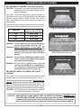
BURNER INSTALLATION
The Real-Fyre burner system must be installed by a qualified professional service technician. Instructions must
be followed carefully to ensure proper performance and full benefit from the burner system. Check to be sure
the burner system is designed and labeled for the type of gas (natural or propane gas) supplied to the
fireplace. Fireplace floor must be level, clean, and smooth.
WARNING: Failure to position the parts in accordance with these diagrams or failure to use only parts
specifically approved with this appliance may result in property damage or personal injury.
Important: When the burner system is installed
outdoors, ensure it is not directly exposed to
the elements (precipitation, rain, wind, etc.).
REFER TO THE BURNER PARTS LIST WHEN FOLLOWING
THESE INSTRUCTIONS.
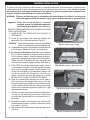
Gas supply stub
Adapter
1. MAKE SURE THE FIREPLACE GAS SUPPLY IS
TURNED OFF.
2. Locate the gas-supply stub inside the fireplace and
remove the cap, if attached (reference Fig. 9-1).
CAUTION:
When removing the cap, make sure the stub does
not turn, loosening the connection inside the wall.
Flex connector
Fig. 9-1 Connect gas supply
3. Place the burner system in the fireplace. Center the burner
in the fireplace. (Reference Fig. 9-2 for orientation.)
4. Be sure gas to the fireplace is off. Remove the adapter
that is loosely connected to the flex connector (coming
off of the burner system). Attach the adapter to the gassupply stub using a pipe compound resistant to all gasses.
Tighten securely. Then attach the open end of the flex
connector to the adapter. Tighten securely (See Fig. 9-1).
5. LEAK TEST: Turn on the fireplace gas supply, and test
at all connections for leaks using the appropriate soapy
water solution. If bubbles appear, a leak is present. Turn
off the gas and tighten at all connections. Repeat until
no leaks are present. If a leak persists, turn off the gas
supply and contact the local gas company or dealer.
NEVER USE A FLAME TO CHECK FOR LEAKS.
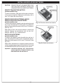
6. Place the (switch/remote receiver) box at the right (or
left) front corner of the fireplace. Be sure to run its wire
through the opening on the right (or left) side of the burner
system, and that the wire remains away from the burner
system and its flame during operation (See Fig. 9-2, right
side placement shown).
Fig. 9-2 Box location, right or left side
Fig. 9-3 Installing hammer screws
7. The burner system must be secured to the fireplace floor.
The unit has two anchoring tabs located at the bottom
front. With the unit centered, mark and then drill two 1/4"
pilot holes.
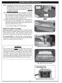
8. Reposition the burner over the pilot holes and insert the
provided hammer screws. Carefully hammer the screws
in as shown in Fig. 9-3.
9. Use a power drill to complete the fastening of the screws
(Fig. 9-4).
Fig. 9-4 Fastening hammer screws
9
BURNER INSTALLATION (cont.)
Note: Should the burner need to be removed for
servicing; first unfasten the screw, then use a flat
head screwdriver to pry up the anchoring tab until
the wedge anchor pops out. See Fig.10-1. The screw
assembly is reusable.
10. The front of the burner has tabs designed to hold the
glass panel in place. First loosen the screws on the tabs
with a screwdriver. Then position the glass panel in place,
secure the tabs up against the panel, and fasten the
screws. Reference Fig. 10-2 and Fig. 10-3.
A
(Remove)
B
(pry up)
Fig. 10-1 If removal is required
11. Remove the protective coating off of the reflective rear
panel and front cover. DO NOT use a sharp object to
remove coating. Install the front cover onto the front of
the burner system (see Fig. 10-4).
Turn off the gas supply prior to proceeding.
REMOTE SYSTEM (if equipped)
For remote models; the remote system is already installed.
Simply attach the included adapter switch to the front of the
remote receiver (see Fig. 10-5). Read the separate remote
instructions to familiarize yourself with the remote system.
Fig. 10-2 Glass panel positioning
For manual models; if a remote system is purchased later,
read and follow the separate remote instructions (packed with
remote) for complete remote installation.
IMPORTANT
Fig. 10-3 Securing glass panel
For all valves, the air MUST be purged from the gas line
before the pilot will light and burn properly. The time needed
to purge will depend on the length of the gas line to the
unit and the amount of time since the unit or gas line was
last used. It may take several minutes before all the air is
purged and the pilot will light and burn properly. Reference
the LIGHTING INSTRUCTIONS section in this manual.
Fig. 10-4 Front cover installed
Install adapter switch
Fig. 10-5 Install switch (if applicable)
10
DECORATIVE MEDIA PLACEMENT
GLASS/GEMS PLACEMENT (purchased separately)
CAUTION:
Glass pieces may have sharp edges. Be careful
handling the glass. Use hand protection, such as
gloves, if necessary.
(Gems shown in burner)
Glass/gems (purchased separately) must be installed on
the burner for the system to operate properly. See the table
below for correct amounts of media for each model. Glass/
gems are available in various colors; contact your dealer for
further details.
Pour the glass/gems directly on top of the burner so that the
burner pan is covered completely and evenly (see Fig. 11-1).
Model Size
Correct Amount of
Fyre Glass/Gems to Use
18"
24"
30"
10.0 lbs
12.5 lbs
15.0 lbs
Fig. 11-1 Glass/gems placement
DO NOT block vents
Important: DO NOT block the rear vents of the burner
system with glass/gems (see Fig. 11-2).
Important: When installing glass on your burner; DO
NOT use the fine glass particles that have
settled at the bottom of the glass bag. These
particles will adversely affect the flame
pattern.
Important: Do not add any additional glass/gems to this
burner system. Any additional glass/gems
may cause unsafe operation.
Fig. 11-2 Keep rear vents clear
(Glass shown on floor)
WARNING: All previously applied loose material
must be removed prior to reapplication.
All replacement loose material must be
purchased from the R.H. Peterson Co.
DECORATIVE MEDIA ON FIREPLACE FLOOR
(optional)
Glass, gems, or Lava-Fyre Granules may be placed on the
fireplace floor as an enhancement to the burner system.
Fig. 11-3 Decorative media floor placement
If purchased; spread the decorative media on the floor of the
fireplace, around the front and sides of the burner system. See
Fig. 11-3 for an example (reflective black glass shown). The
media may be placed around and on top of the (switch / remote
receiver) box. Leave the front of the box clear for control access.
CAUTION: DO NOT place any of this additional media into
or onto the burner system, or behind it.
CAUTION: BURN HAZARD. GLASS AND/OR GEMS ON BURNER SYSTEM WILL REMAIN HOT
FOR SOME TIME AFTER USE. You must maintain the placement as shown to ensure proper
operation of the burner system. If you need to reposition any media to maintain the proper
layout, use heat-resistant gloves or allow media adequate time to cool before handling.
11
INSTALLING/REPLACING BATTERIES
CAUTION: ENSURE THE UNIT IS CONNECTED TO THE
GAS LINE AND HAS BEEN TESTED FOR
LEAKS BEFORE YOU INSERT BATTERIES.
REMOTE TRANSMITTER BATTERY
(remote models only)
"D" batteries
"AA" batteries
To access the battery, slide open the lid found on the back
of the remote transmitter. Replace the old battery with a
new "12v" battery. Re-secure the lid.
REMOTE RECEIVER BATTERIES AND/OR
REMOTE RECEIVER BOX BATTERIES
(remote models only)
To access the batteries, locate the remote receiver box and
turn it over. The exposed "D" battery pack is for electronic
ignition. Replace the old batteries with (2) new "D" batteries.
(See Fig. 12-1.)
Fig. 12-1 Remote receiver box batteries
"D" batteries
Slide open the lid on the remote receiver to expose the
batteries. Replace the old batteries with (4) new "AA"
batteries. (See Fig. 12-1.) Replace the lid.
SWITCH BOX BATTERIES
(remote models only)
To access the batteries, locate the switch box and turn it
over. The exposed "D" battery pack is for electronic ignition.
Replace the old batteries with (2) new "D" batteries. (See
Fig. 12-2.)
When battery replacement is complete; properly place the
(switch / remote receiver) box in the fireplace as instructed
in the BURNER INSTALLATION section of this manual.
Important: Low/dead batteries will affect burner
system operation. Replace batteries any
time the burner will not turn on.
12
Fig. 12-2 Switch box batteries
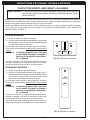
LIGHTING INSTRUCTIONS - REMOTE MODEL
FOR YOUR SAFETY, READ BEFORE LIGHTING
WARNING: If you do not follow these instructions exactly, a fire or explosion may result, causing
property damage, personal injury, or loss of life.
Do not use this appliance if any part has been underwater. Immediately call for a qualified professional
service technician to inspect the appliance and to replace any part of the control system and any gas control
that has been underwater.
BEFORE LIGHTING, smell all around the burner area for gas. Be sure to smell next to the floor, as some
gas is heavier than air and will settle on the floor. IF YOU SMELL GAS, FOLLOW THE INSTRUCTIONS
ON PG. 1.
MANUAL LIGHTING
1. Turn off any electrical appliance.
2. Press the remote receiver control to the ON position.
This transmits a rapid series of sparks at the pilot head
and will ignite the gas.
ADJ.
LEARN
Sparks cease when the pilot flame is lit and stable. After a
short time, the pilot will then light the main burner.
CAUTION: IF THE BURNER DOES NOT IGNITE WITHIN
20 SECONDS, TURN OFF, WAIT 5 MINUTES,
THEN REPEAT STEPS 1. AND 2. ABOVE.
If the pilot will not stay lit after several tries, turn the receiver to
OFF and contact a qualified professional service technician
or gas supplier.
OFF REMOTE
ON
Fig. 13-1 Remote receiver
REMOTE LIGHTING
1. Turn off any electrical appliance.
2. Press the remote receiver control to the REMOTE
position. Then press the ON button on the remote
transmitter. This transmits a rapid series of sparks at
the pilot head and will ignite the gas.
Sparks cease when the pilot flame is lit and stable. after a
short time, the pilot will then light the main burner.
ON
OFF
CAUTION: IF THE BURNER DOES NOT IGNITE WITHIN
20 SECONDS, TURN OFF, WAIT 5 MINUTES,
THEN REPEAT STEPS 1. AND 2. ABOVE.
If the pilot will not stay lit after several tries, turn the receiver to
OFF and contact a qualified professional service technician
or gas supplier.
In addition to these instructions; reference the separate
remote instructions for further details on the remote system.
Fig. 13-2 Remote transmitter
13
INSTRUCTIONS D'ÉCLAIRAGE - MODÈLE À DISTANCE
POUR VOTRE SÛRETÉ, LISEZ AVANT L'ALLUMAGE
AVERTISSEMENT: Si vous ne suivez pas ces instructions exactement, une incendie ou une explosion
peut résulter, entraînant des dégats matériels, le dommage corporel, ou des
pertes humaines.
N'employez pas cet appareil si n'importe quelle partie a été sous-marine. Réclamez immédiatement un technicien
qualifié de service professionnel pour inspecter l'appareil et pour remplacer n'importe quelle partie du système de
contrôle et de n'importe quelle commande de gaz qui a été sous-marine.
AVANT L'ALLUMAGE, sentez tous autour du secteur de brûleur pour le gaz. Soyez sûr de sentir à côté du plancher,
car un certain gaz est plus lourd que l'air et arrangera sur le plancher. SI VOUS SENTEZ LE GAZ, SUIVEZ LES
INSTRUCTIONS À LA PAGE. 1.
ÉCLAIRAGE MANUEL
1. Arrêtez n'importe quel appareil électrique.
2. Pressez la commande à distance de récepteur à la position de
fonctionnement. Ceci transmet une série rapide d'étincelles
à la tête pilote et mettra à feu le gaz.
Les étincelles cessent quand la flamme pilote est allumée et
écurie. Après une brève durée, le pilote allumera alors le brûleur
principal.
ATTENTION:
SI LE BRÛLEUR NE MET PAS À FEU DANS
20 SECONDES, ÉTEIGNEZ, ATTENDEZ 5
MINUTES, ALORS RÉPÉTEZ LES ÉTAPES 1.
ET 2. CI-DESSUS.
ADJ.
LEARN
OFF REMOTE
ON
Fig. 14-1 Récepteur à distance
Si le pilote ne restera pas allumé après que plusieurs essais,
tournent le récepteur à AU LOIN et contactent un fournisseur
qualifié de technicien ou de gaz de service professionnel.
ÉCLAIRAGE À DISTANCE
1. Arrêtez n'importe quel appareil électrique.
2. Pressez la commande de boîte de commutateur dans la
position À DISTANCE. Appuyez sur alors DESSUS le bouton
sur l'émetteur à distance. Ceci transmet une série rapide
d'étincelles à la tête pilote et mettra à feu le gaz.
ON
Les étincelles cessent quand la flamme pilote est allumée et
écurie. Après une brève durée, le pilote allumera alors le brûleur
principal.
OFF
ATTENTION:
SI LE BRÛLEUR NE MET PAS À FEU DANS
20 SECONDES, ÉTEIGNEZ, ATTENDEZ 5
MINUTES, ALORS RÉPÉTEZ LES ÉTAPES 1.
ET 2. CI-DESSUS.
Si le pilote ne restera pas allumé après que plusieurs essais,
tournent le récepteur à AU LOIN et contactent un fournisseur
qualifié de technicien ou de gaz de service professionnel.
En plus de ces instructions; mettez en référence les instructions à
distance séparées pour d'autres détails sur le système à distance.
Fig. 14-2 Émetteur à distance
14
LIGHTING INSTRUCTIONS - REMOTE MODEL (cont.)
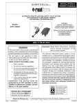
PILOT APPEARANCE
Periodically check the pilot for proper flame pattern. The
pilot flame should encircle the generator tip, and is preset
at the factory (see Fig. 15-1).
If the pilot flame burns incorrectly; shut down completely
and contact a qualified professional service technician.
SHUTTING DOWN
1. Simply press the receiver control to the OFF position
when manually operated. The gas flow will cease, and
all the flames (main burner and pilot) will go out.
2. For remote operation, press the OFF button on the
transmitter.
15
Fig. 15-1 Proper pilot flame
INSTRUCTIONS D'ÉCLAIRAGE - MODÈLE À DISTANCE (continu)
ASPECT PILOTE
Examinez périodiquement le pilote pour assurer le modèle
approprié de flamme. La flamme pilote devrait encercler le
bout de générateur, et est préréglée à l'usine (voir la Fig.
16-1).
Si la flamme pilote brûle inexactement; arrêtez
complètement et contactez un technicien qualifié de
service professionnel.
ARRÊT
1. Pressez simplement la commande de récepteur
à la position de repos si manuel. L'écoulement de
gaz cessera, et toutes les flammes (brûleur et pilote
principaux) sortiront.
2. Pour l'opération à distance, appuyez sur AU LOIN le
bouton sur l'émetteur.
16
Fig. 16-1 Flamme pilote appropriée
LIGHTING INSTRUCTIONS - MANUAL MODEL
FOR YOUR SAFETY, READ BEFORE LIGHTING
WARNING: If you do not follow these instructions exactly, a fire or explosion may result, causing
property damage, personal injury, or loss of life.
Do not use this appliance if any part has been underwater. Immediately call for a qualified professional
service technician to inspect the appliance and to replace any part of the control system and any gas control
that has been underwater.
BEFORE LIGHTING, smell all around the burner area for gas. Be sure to smell next to the floor, as some
gas is heavier than air and will settle on the floor. IF YOU SMELL GAS, FOLLOW THE INSTRUCTIONS
ON PG. 1.
1. Turn off any electrical appliance.
2. Press the "I" (Ignite) switch on the front of the switch
box. This transmits a rapid series of sparks at the pilot
head and will ignite the gas.
Sparks cease when the pilot flame is lit and stable. After a
short time, the pilot will then light the main burner.
CAUTION: IF THE BURNER DOES NOT IGNITE WITHIN
20 SECONDS, TURN OFF, WAIT 5 MINUTES,
THEN REPEAT STEPS 1. AND 2. ABOVE.
If the pilot will not stay lit after several tries, turn the switch
box to "O" (OFF) and contact a qualified professional service
technician or gas supplier.
I
O
Fig. 17-1 ON/OFF switch
PILOT APPEARANCE
Periodically check the pilot for proper flame pattern. The
pilot flame should encircle the generator tip, and is preset
at the factory (see Fig. 17-2).
If the pilot flame burns incorrectly; shut down completely
and contact a qualified professional service technician.
SHUTTING DOWN
1. Simply press the "O" (OFF) switch on the front of the
switch box. The gas flow will cease, and all the flames
(main burner and pilot) will go out.
Fig. 17-2 Proper pilot flame
17
INSTRUCTIONS D'ÉCLAIRAGE - MODÈLE MANUEL
POUR VOTRE SÛRETÉ, LISEZ AVANT L'ALLUMAGE
AVERTISSEMENT: Si vous ne suivez pas ces instructions exactement, une incendie ou une explosion
peut résulter, entraînant des dégats matériels, le dommage corporel, ou des pertes
humaines.
N'employez pas cet appareil si n'importe quelle partie a été sous-marine. Réclamez immédiatement un
technicien qualifié de service professionnel pour inspecter l'appareil et pour remplacer n'importe quelle
partie du système de contrôle et de n'importe quelle commande de gaz qui a été sous-marine.
AVANT L'ALLUMAGE, sentez tous autour du secteur de brûleur pour le gaz. Soyez sûr de sentir à côté du
plancher, car un certain gaz est plus lourd que l'air et arrangera sur le plancher. SI VOUS SENTEZ LE GAZ,
SUIVEZ LES INSTRUCTIONS À LA PAGE. 1.
1. Arrêtez n'importe quel appareil électrique.
2. Pressez le "I" (Mettez à feu) branchez l'avant de la
boîte de commutateur. Ceci transmet une série rapide
d'étincelles à la tête pilote et mettra à feu le gaz.
Les étincelles cessent quand la flamme pilote est allumée
et écurie. Après une brève durée, le pilote allumera alors
le brûleur principal.
ATTENTION: SI LE BRÛLEUR NE MET PAS À FEU DANS
20 SECONDES, ÉTEIGNEZ, ATTENDEZ
5 MINUTES, ALORS RÉPÉTEZ LES
ÉTAPES 1. ET 2. CI-DESSUS.
Si le pilote ne restera pas allumé après que plusieurs essais,
tournent la boîte de commutateur au "O" (AU LOIN) et
contactez un fournisseur qualifié de technicien ou de gaz
de service professionnel.
I
O
Fig. 18-1 Commutateur "MARCHE/ARRÊT"
ASPECT PILOTE
Examinez périodiquement le pilote pour assurer le modèle
approprié de flamme. La flamme pilote devrait encercler le
bout de générateur, et est préréglée à l'usine (voir la Fig.
18-2).
Si la flamme pilote brûle inexactement ; arrêtez
complètement et contactez un technicien qualifié de
service professionnel.
ARRÊT
1. Pressez simplement le "O" (AU LOIN) branchez
l'avant de la boîte de commutateur. L'écoulement de
gaz cessera, et toutes les flammes (brûleur et pilote
principaux) sortiront.
18
Fig. 18-2 Flamme pilote appropriée
CLEANING AND SERVICING SAFETY INFORMATION
Note: Regular cleaning and servicing will be necessary to ensure proper pilot operation and proper burn
characteristics.
Always shut off the gas to the appliance while performing service work.
Allow the appliance to cool before servicing.
Installation, service, and repair must be done by an NFI Certified or other qualified professional
service technician. The appliance MUST be inspected before use, and cleaned at least annually
to prevent burner shutdown, sooting, odors, etc. by a qualified professional service technician. It
must be checked for clean burning operation and proper pilot appearance, with the correct tools to
service this unit. More frequent cleaning may be required. Excessive lint can build up on this unit from
carpeting, bedding material, pet hairs, or other particles in the air. It is imperative that all control components
and compartments, burner(s), air shutters, and circulating air passageways of the appliance be kept clean
and free of all obstructions.
In addition, a periodic examination and cleaning of the solid-fuel-burning fireplace venting system should
be conducted by a qualified professional service technician.
Any safety screen or guard removed for servicing must be replaced prior to operating this appliance.
TO CLEAN THE BURNER SYSTEM
1. Remove the glass/gems. Use a vacuum cleaner to remove
loose particles from all surfaces of the burner system. Do
not use cleaning fluids.
2. Dust the assembly and the burner. Using a compressed
air duster (commonly available at computer, electronic, or
office supply stores); blow through all of the burner ports,
and the pilot assembly area.
3. Replace batteries as needed.
Fig. 19-1
Pilot (on side)
Burner ports
24" remote model shown
4. Reinstall the glass/gems as instructed in this manual.
If, after a period of use, the flames start to exhibit unusual shapes and behavior, or the burners fail to ignite
smoothly, the burner ports may require some cleaning. If this happens, it is preferable to contact the nearest
dealer to get the appliance serviced.
Do not remove the rating plates or the warning tags. These are an integral safety and identification
component of this appliance.
We recommend following these instructions at the beginning of each fireplace season and as needed
throughout the year, depending on your usage pattern and the environmental conditions in your
home. More frequent cleaning and maintenance may be necessary when burning propane gas than
with natural gas.
FLAME DESCRIPTION
Observe the flames. The main burner flames should be blue at the base and a combination of blue/yellow at
the body and at the tips. They should be approximately 8" above the glass/gems, with the center flame being
the tallest. (See cover photo for example.)
19
NOTES PAGE
Please use this page to record any information that you may want to have at hand.
20
TROUBLESHOOTING
POSSIBLE CAUSE
1
SOLUTIONS
BURNER SHUTTING DOWN DURING OPERATION
A. Insufficient or excessive gas
pressure
A1. Check gas pressure (Read G.- I. of IMPORTANT PRE-INSTALLATION AND
FIREPLACE SAFETY INFORMATION section, & check with local gas company).
A2. Other gas appliances may be on the same gas line, dropping gas pressure
to log set. Check pressures with everything operating to ensure adequate
pressure.
B. Flue area, fireplace, or
damper dirty from soot
B. Clean around, above, and under damper thoroughly. Clean fireplace, removing
loose material, including soot and creosote.
C. Fireplace too small for unit
C. Ensure minimum requirements are met. (See FIREPLACE SIZE
REQUIREMENT section in this owner’s manual.)
D. P i l o t f l a m e l i f t i n g o f f
thermocouple/generator
D. Check gas pressure (see section A1).
E. Pilot (remote compatible)
E. Contact your dealer for instructions on replacement.
F. Blockages on burner
F. Vacuum any lava granules or material that may have fallen onto burner port
area.
2
PILOT WILL NOT LIGHT
A. P i l o t f l a m e l i f t i n g o f f
thermocouple/generator
A. Check gas pressure (see Section 1, A1 of this table).
B. Electronic spark not lighting
pilot
B. Check to ensure sparking when activated.
C. Ignitor electrode wire loose
C. Check wiring and reconnect any loose wiring.
D. Gas supply off/manual
shutoff valve closed
D. Turn on gas supply or open manual shutoff valve.
E. Air in gas line
E. Bleed the gas supply line and repeat LIGHTING INSTRUCTIONS until air is
removed.
F. Pilot hood blocked
F. Check for debris or dirt / clean pilot
3
LOW FLAME HEIGHT
A. Gas pressure
A. Check gas pressure (see Section 1, A1 of this table).
B. Propane tank running low
B. Fill tank completely.
4
A. Burner orifice clogged
5
BURNER NOT BURNING EVENLY
A. Clean burner orifice.
ODORS
A. Gas leak
A. Shut off gas, if possible. Follow instructions on front page. Have a qualified
professional installer or the gas company correct all leaks.
B. New home, new carpet, or
new paint
B. When these odors are drawn into the fireplace, this may cause objectionable
odors. Thoroughly ventilate the area before restarting your burner system.
21
TROUBLESHOOTING (Cont.)
POSSIBLE CAUSE
SOLUTIONS
SOOTING
6
A. Low gas pressure
A. Check gas pressure (see Section 1, A1 of this table).
B. Drafts in room
B. Eliminate drafts by closing heating and air conditioning
vents, returns, and outside air vents. Fans blowing directly
into fireplace should be turned off when set is operating.
C. Air shutters blocked (if applicable)
C. Air shutters are blocked with debris. Vacuum debris away
from air shutter.
D. Using a product other than Real-Fyre® glass/
gems with burner
D. Make sure only Real-Fyre® glass/gems are used with your
vent-free burner.
E. Using natural-gas burner on propane gas or
propane burner on natural gas
E. If the gas listed on the nameplate does not match the gas
you are burning, shut down the burner system immediately
and completely (including pilot) following the steps in
the LIGHTING INSTRUCTIONS section. Then call your
dealer.
F. Adding any accessories to burner system
F. Shut down log set and take off any accessories that do not
belong with the system.
7
PILOT WILL NOT STAY LIT
A. Valve won’t hold
A. Contact your dealer for instructions on replacement.
B. Pilot hood not aimed at thermocouple
B. Pilot hood bent; replace pilot or angle pilot hood properly so
pilot flame hits thermocouple.
C. Pilot line bent
C. Replace pilot line.
D. Thermocouple is loose
D. Tighten thermocouple nut at gas control valve.
E. Thermocouple cracked or worn out
E. Replace thermocouple.
F. Excessive down draft
F. Install chimney cap / Outside chimney too close to other
peaks / Check chimney flue for proper height / Poorly
designed chimney
8
BURNER WILL NOT TURN ON
A. Low/dead batteries in remote transmitter (if
applicable) AND/OR (switch/receiver) box
A. Replace batteries as needed.
22
ELECTRONIC PILOT TROUBLESHOOTING
Detail A
Electrode (A)
When adjusting the spark electrode (if
necessary); NEVER adjust the electrode by
bending the wire. ALWAYS adjust the electrode
by loosening the retainer nut(s), then adjust
accordingly.
The minimum gap between the spark electrode/
sensor electrode and the pilot flame hood is
1/8". The maximum is 5/32".
Hood
Spark electrode
Electrode Ceramic
Threaded barrel
1/8"
min. gap
Sensor
electrode
1/8"
min. gap
Fig. A-1
If the electrode ceramic is loose in the threaded
barrel; the pilot assembly must be replaced.
Retainer nuts
Detail B
Terminal Connections (B)
All of the connections on the control module
must be properly attached. If the spade
terminals are loose; inspect to ensure they
correctly appear as detailed below. Use needle
nose pliers to clamp down on the center/sides
of the terminals if needed (to provide a tight fit.)
Detail C
(Fig. C-1)
Spade Terminal Detail
(Fig. B-1)
CORRECT
INCORRECT
Ensure that spade terminals
(S and I) are attached securely
Ensure that multi-wire
connector is properly
locked in place
Control Module
(DESIGN MAY VARY)
DO NOT bundle
tightly together
as shown
(Fig. B-2)
Tighten terminals if needed
Assembly Wires (C)
DO NOT bundle the excess pilot assembly
wires tightly together as this can reduce the
intensity of the spark.
(Fig. B-3)
23
WARRANTY
PETERSON VENTED DECORATIVE GAS APPLIANCE
LIMITED WARRANTY
Robert H. Peterson Co. ("RHP") warrants your Real Fyre® vented decorative gas appliance to be free from defects in material and
workmanship.
Peterson vented ceramic refractory gas logs are warranted for as long as you own them (lifetime).
Peterson vented burner assemblies are WARRANTED for TEN (10) YEARS. Peterson vented outdoor stainless-steel burner
assemblies are warranted for FIVE (5) YEARS.
Peterson glass, gems, nuggets, and fiber-ceramic blend gas logs are warranted for FIVE (5) YEARS.
SPK-26 controls are warranted for THREE (3) YEARS.
APK-17 controls (including -17 valve) are warranted for TWO (2) YEARS.
All other Peterson valves, pilots, and controls are warranted for ONE (1) YEAR (excluding batteries).
A COPY OF YOUR SALES SLIP FOR PROOF OF PURCHASE IS REQUIRED
This warranty applies to the original purchaser for products which are installed in the United States or Canada and which are operated and maintained
as intended for single family residential usage. This warranty is valid only with proof of purchase, shall commence on the date of purchase, and shall
terminate (both as to original and any replacement products) on the anniversary date of the original purchase of the product stated on the above schedules.
This warranty covers defects in material and workmanship. This warranty does not cover parts which become defective as a result of negligence, misuse,
use not in compliance with the Owner’s Manual/Installation Instructions, accidental damage, improper handling, improper storage, improper installation,
lack of required routine maintenance (as specified in the Owner’s Manual/Installation Instructions), electrical damage, local gas impurities or failure to
protect against combustibles. Product must be installed (and gas must be connected) as specified in the Owner’s Manual/Installation Instructions by
a qualified professional installer. Modifications to products which are not specifically authorized will void this warranty. Accessories, parts, valves,
remotes, etc. when used must be Peterson products or this warranty is void. Warrantied items will be repaired or replaced at Peterson’s sole discretion.
This warranty does not apply to rust, corrosion, oxidation, or discoloration unless the affected part becomes inoperable.
This warranty does not cover labor or labor related charges, except as provided by separate specific written programs from the Peterson Co. All repair
work must be performed by a qualified professional service person and requires prior approval of Peterson.
Peterson may require the defective product or part to be returned to the factory to determine the cause of failure. Peterson will pay freight charges if
the product or part is determined to be defective. This warranty does not cover breakage in shipment from our (Independent) distributor to its customer
if the damage is determined to have occurred during that shipment.
This warranty specifically excludes liability for indirect, incidental, or consequential damages. Some states and provinces do not allow the exclusion
or limitation of incidental or consequential damages, so the above exclusion may not apply to you. This warranty gives you specified legal rights, and
you may have other rights that vary from state to state or province.
For additional information regarding this warranty, or to place a warranty claim, contact the R. H. Peterson dealer where the product was purchased.
TO REGISTER YOUR PRODUCT ONLINE GO TO: WWW.RHPETERSON.COM,
AND CLICK ON PRODUCT REGISTRATION. THANK YOU FOR YOUR PURCHASE.
FOR USE IN THE COMMONWEALTH OF MASSACHUSETTS
INSTALLATION OF THIS APPLIANCE MUST BE PERFORMED BY A MASSACHUSETTS
LICENSED PLUMBER OR GAS FITTER ONLY.
CONNECTOR KITS USED FOR INSTALLATION AND OPERATION OF THIS APPLIANCE
MUST NOT BE MORE THAN 36" IN LENGTH.
FIREPLACE DAMPER MUST BE REMOVED OR PERMANENTLY FIXED/WELDED IN FULL
OPEN POSITION PRIOR TO INSTALLING THIS PRODUCT.
Quality Check
Burner Orifices Nat.
Date:_________________
L.P.
Leak Test: ___________ Model#:
___________________
Main:
____ ____
Burn Test: ___________ Serial#:
___________________
Other:
____ ____
Gas Type:
Nat. / L.P.
Air Shutter: ___________________
Inspector:
___________________
Robert H. Peterson Co. • 14724 East Proctor Avenue • City of Industry, CA 91746
24