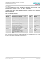
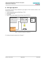
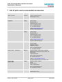
1
Siemens Cellular Engine
Hardware
Interface
Description
Version: 01.05
DocID: TC35i T HD v01.05
TC35i Terminal Hardware Interface Description
Confidential / Released
Document Name:
TC35i Terminal Hardware Interface Description
Version:
Date:
DocId:
Status:
01.05
10.07.2003
TC35i_T_HD_v01.05
Confidential / Released
General notes
Product is deemed accepted by Recipient and is provided without interface to Recipient´s products.
The Product constitutes pre-release version and code and may be changed substantially before
commercial release. The Product is provided on an “as is” basis only and may contain deficiencies or
inadequacies. The Product is provided without warranty of any kind, express or implied. To the
maximum extent permitted by applicable law, Siemens further disclaims all warranties, including
without limitation any implied warranties of merchantability, fitness for a particular purpose and
noninfringement of third-party rights. The entire risk arising out of the use or performance of the
Product and documentation remains with Recipient. This Product is not intended for use in life support
appliances, devices or systems where a malfunction of the product can reasonably be expected to
result in personal injury. Applications incorporating the described product must be designed to be in
accordance with the technical specifications provided in these guidelines. Failure to comply with any of
the required procedures can result in malfunctions or serious discrepancies in results. Furthermore, all
safety instructions regarding the use of mobile technical systems, including GSM products, which also
apply to cellular phones must be followed. Siemens AG customers using or selling this product for use
in any applications do so at their own risk and agree to fully indemnify Siemens for any damages
resulting from illegal use or resale .To the maximum extent permitted by applicable law, in no event
shall Siemens or its suppliers be liable for any consequential, incidental, direct, indirect, punitive or
other damages whatsoever (including, without limitation, damages for loss of business profits,
business interruption, loss of business information or data, or other pecuniary loss) arising out the use
of or inability to use the Product, even if Siemens has been advised of the possibility of such damages.
Subject to change without notice at any time.
Copyright notice
Transmittal, reproduction, dissemination and/or editing of this document as well as utilization of its
contents and communication thereof to others without express authorization are prohibited. Offenders
will be held liable for payment of damages. All rights created by patent grant or registration of a utility
model or design patent are reserved.
Copyright © Siemens AG 2003
Trademark notice
MS Windowsâ is a registered trademark of Microsoft Corporation.
TC35i_T_HD_v01.05
Page 2/37
10.07.2003
TC35i Terminal Hardware Interface Description
Confidential / Released
Contents
0
Document history....................................................................................................... 5
1
Introduction ................................................................................................................ 6
1.1
1.2
1.3
1.4
References ......................................................................................................... 6
Standards ........................................................................................................... 7
Safety precautions .............................................................................................. 8
Terms and abbreviations....................................................................................10
2
Key features of TC35i Terminal ................................................................................12
3
Interface description.................................................................................................13
3.1
3.2
3.3
3.4
3.5
3.6
4
Overview ............................................................................................................13
Block diagram of a GSM application ..................................................................14
The TC35i GSM engine .....................................................................................15
Operating modes ...............................................................................................16
Terminal circuit...................................................................................................17
3.5.1 Power supply and On/Off control ............................................................18
3.5.1.1 Maximum number of turn/on & turn/off cycles ......................................19
3.5.2 RTC ........................................................................................................20
Upgrading TC35i Terminal firmware ..................................................................20
3.6.1 RS-232 interface.....................................................................................20
3.6.2 Audio interface........................................................................................22
3.6.3 Radio interface .......................................................................................25
3.6.4 SIM interface ..........................................................................................26
3.6.5 Status LED .............................................................................................26
Mechanical characteristics and mounting advice ..................................................27
4.1
Attaching the terminal ........................................................................................28
5
Electrical and environmental characteristics..........................................................29
6
Full type approval......................................................................................................35
6.1
6.2
6.3
7
Restrictions ........................................................................................................36
CE Conformity....................................................................................................36
EMC...................................................................................................................36
List of parts and recommended accessories..........................................................37
TC35i_T_HD_v01.05
Page 3/37
10.07.2003
TC35i Terminal Hardware Interface Description
Confidential / Released
Figures
Figure 1: Block diagram of a TC35i Terminal application (example).....................................14
Figure 2: TC35i GSM engine................................................................................................15
Figure 3: TC35i Terminal circuit block diagram ....................................................................17
Figure 4: Female 6-pole Western plug for power supply, ignition, power down ....................18
Figure 5: Pin assignment RS-232 (D-Sub 9-pole female).....................................................20
Figure 6: Audio Western plug (4-pole female) ......................................................................22
Figure 7: Audio block diagram..............................................................................................22
Figure 8: Antenna connector circuit on TC35i module ..........................................................25
Figure 9: Recommended antenna connector........................................................................25
Figure 10: Design drawing ...................................................................................................27
Figure 11: Recommended screws ........................................................................................28
Figure 12: Attaching TC35i Terminal onto a top-hat rail .......................................................28
Figure 13: Reference equipment for approval ......................................................................35
Tables
Table 1: Terms and abbreviations ........................................................................................10
Table 2: Key features ...........................................................................................................12
Table 3: Overview of operating modes .................................................................................16
Table 4: Female 6-pole Western plug for power supply, ignition, power down .....................19
Table 5: 9-pole D-Sub (female) RS-232 ...............................................................................21
Table 6: Audio modes ..........................................................................................................23
Table 7: Coding of the green status LED .............................................................................26
Table 8: Mechanical characteristics......................................................................................27
Table 9: Absolute maximum ratings .....................................................................................29
Table 10: Operating conditions.............................................................................................29
Table 11: Characteristics power supply................................................................................30
Table 12: Characteristics (requirements) On/Off control lines ..............................................31
Table 13: Characteristics (requirements) RS-232 interface ..................................................31
Table 14: Characteristics (requirements) audio interface .....................................................32
Table 15: AT adjustable parameters ....................................................................................33
Table 16: Air interface ..........................................................................................................34
TC35i_T_HD_v01.05
Page 4/37
10.07.2003
TC35i Terminal Hardware Interface Description
Confidential / Released
0 Document history
Preceding document: "TC35i Terminal Hardware Interface Description" Version 00.40
New document: "TC35i Terminal Hardware Interface Description" Version 01.05
Chapter
Page
What is new
0
6
Added Application Note 24: Application Developers’ Guide
1.2, 7
6, 37
TC35i Terminal now fully type approved and labeled with CE mark
TC35i_T_HD_v01.05
Page 5/37
10.07.2003
TC35i Terminal Hardware Interface Description
Confidential / Released
1 Introduction
This document describes the hardware of the Siemens TC35i Terminal. The information are
intended for users, developers or manufacturers who design and build cellular applications
beyond the standard setup. The scope of this document includes interface specifications,
electrical issues and mechanical characteristics of TC35i Terminal. It specifies standards
pertaining to wireless applications and outlines requirements that must be adhered to for
successful product design. The TC35i Terminal is a compact GSM modem for the transfer of
data, voice, SMS and faxes in GSM networks. Industrial standard interfaces and an
integrated SIM card reader allow using TC35i Terminal easily as a dual band GSM terminal.
The functionality of the Terminal corresponds to the features of the TC35i module.
1.1 References
[1]
[2]
[3]
[4]
[5]
[6]
[7]
[8]
[9]
TC35i AT Command Set for TC35i and TC35i Terminal, Version 01.05
Release Note, Version 01.05
Application Note 16: Upgrading TC35i Terminal firmware
Application Note 02: Audio Interface Design
Application Note 24: Application Developers’ Guide
Remote Sat User’s Guide
Multiplexer User’s Guide
Multiplexer Driver Developer’s Guide for Windows 2000 and Windows XP
Multiplexer Driver Installation Guide for Windows 2000 and Windows XP
Prior to using the GSM engine, be sure to carefully read and understand the latest product
information provided in the Release Notes.
To visit the Siemens Website you can use the following link:
http://www.siemens.com/wm
TC35i_T_HD_v01.05
Page 6/37
10.07.2003
TC35i Terminal Hardware Interface Description
Confidential / Released
1.2 Standards
TC35i Terminal has been approved to comply with the directives and standards listed below
and is labeled with the CE conformity mark.
Directives
99/05/EC
Directive of the European Parliament and of the council of 9 March
1999 on radio equipment and telecommunications terminal
equipment and the mutual recognition of their conformity, in short
referred to as R&TTE Directive 1999/5/EC
89/336/EC
Directive on electromagnetic compatibility
73/23/EC
Directive on electrical equipment designed for use within certain
voltage limits (Low Voltage Directive)
95/54/EC
Automotive EMC Directive
Standards of type approval
ETS 300 607-1
Digital cellular telecommunications system (Phase 2);
Mobile Station (MS) conformance specification;
(equal GSM 11.10-1=>equal 3GPP TS 51.010-1)
EN 301 511
V7.0.1 (2000-12) Candidate Harmonized European Standard
(Telecommunications series) Global System for Mobile
communications (GSM); Harmonized standard for mobile stations in
the GSM 900 and DCS 1800 bands covering essential requirements
under article 3.2 of the R&TTE directive (1999/5/EC) (GSM 13.11
version 7.0.1 Release 1998)
EN 301 489-7
V1.1.1 (2000-09) Candidate Harmonized European Standard
(Telecommunications series) Electro Magnetic Compatibility and
Radio spectrum Matters (ERM); Electro Magnetic Compatibility
(EMC) standard for radio equipment and services; Part 7: Specific
conditions for mobile and portable radio and ancillary equipment of
digital cellular radio telecommunications systems (GSM and DCS)
EN 60 950
Safety of information technology equipment (2000)
Requirements of quality
IEC 60068
Environmental testing
DIN EN 60529
IP codes
TC35i_T_HD_v01.05
Page 7/37
10.07.2003
TC35i Terminal Hardware Interface Description
Confidential / Released
1.3 Safety precautions
The following safety precautions must be observed during all phases of the operation,
usage, service or repair of any cellular terminal or mobile incorporating TC35i Terminal.
Manufacturers of the cellular terminal are advised to convey the following safety information
to users and operating personnel and to incorporate these guidelines into all manuals
supplied with the product. Failure to comply with these precautions violates safety standards
of design, manufacture and intended use of the product. Siemens AG assumes no liability
for customer failure to comply with these precautions.
When in a hospital or other health care facility, observe the restrictions on the
use of mobiles. Switch the cellular terminal or mobile off, if instructed to do so
by the guidelines posted in sensitive areas. Medical equipment may be
sensitive to RF energy.
The operation of cardiac pacemakers, other implanted medical equipment
and hearing aids can be affected by interference from cellular terminals or
mobiles placed close to the device. If in doubt about potential danger, contact
the physician or the manufacturer of the device to verify that the equipment is
properly shielded. Pacemaker patients are advised to keep their hand-held
mobile away from the pacemaker, while it is on.
Switch off the cellular terminal or mobile before boarding an aircraft. Make
sure it cannot be switched on inadvertently. The operation of wireless
appliances in an aircraft is forbidden to prevent interference with
communications systems. Failure to observe these instructions may lead to
the suspension or denial of cellular services to the offender, legal action, or
both.
Do not operate the cellular terminal or mobile in the presence of flammable
gases or fumes. Switch off the cellular terminal when you are near petrol
stations, fuel depots, chemical plants or where blasting operations are in
progress. Operation of any electrical equipment in potentially explosive
atmospheres can constitute a safety hazard.
Your cellular terminal or mobile receives and transmits radio frequency
energy while switched on. Remember that interference can occur if it is used
close to TV sets, radios, computers or inadequately shielded equipment.
Follow any special regulations and always switch off the cellular terminal or
mobile wherever forbidden, or when you suspect that it may cause
interference or danger.
Road safety comes first! Do not use a hand-held cellular terminal or mobile
when driving a vehicle, unless it is securely mounted in a holder for handsfree
operation. Before making a call with a hand-held terminal or mobile, park the
vehicle.
Handsfree devices must be installed by qualified personnel. Faulty installation
or operation can constitute a safety hazard.
TC35i_T_HD_v01.05
Page 8/37
10.07.2003
TC35i Terminal Hardware Interface Description
Confidential / Released
SOS
IMPORTANT!
Cellular terminals or mobiles operate using radio signals and cellular
networks cannot be guaranteed to connect in all conditions. Therefore, you
should never rely solely upon any wireless device for essential
communications, for example emergency calls.
Remember, in order to make or receive calls, the cellular terminal or mobile
must be switched on and in a service area with adequate cellular signal
strength.
Some networks do not allow for emergency calls if certain network services
or phone features are in use (e.g. lock functions, fixed dialling etc.). You may
need to deactivate those features before you can make an emergency call.
Some networks require that a valid SIM card be properly inserted in the
cellular terminal or mobile.
If a power supply unit is used to supply the device, it must meet the demands
placed on SELV circuits in accordance with EN60950. The maximum
permissible connection length between the device and the supply source
should not exceed 3m.
According to the guidelines for human exposure to radio frequency energy,
an antenna connected to the FME jack of the device should be placed at
least 20cm away from human bodies.
TC35i_T_HD_v01.05
Page 9/37
10.07.2003
TC35i Terminal Hardware Interface Description
Confidential / Released
1.4 Terms and abbreviations
Table 1: Terms and abbreviations
Abbreviation
Description
ADC
Analog-to-Digital Converter
ARP
Antenna Reference Point
ASIC
Application Specific Integrated Circuit
ATC
AT Cellular
BTS
Base Transceiver Station
CB
Cell Broadcast
CODEC
Coder-Decoder
CPU
Central Processing Unit
DCE
Data Circuit terminating Equipment
DSB
Development Support Box
DSP
Digital Signal Processor
DSR
Data Set Ready
DTR
Data Terminal Ready
EFR
Enhanced Full Rate
EGSM
Enhanced GSM
EMC
Electromagnetic Compatibility
ESD
Electrostatic Discharge
ETS
European Telecommunication Standard
FDMA
Frequency Division Multiple Access
FR
Full rate
G.C.F.
GSM Conformity Forum
GSM
Global Standard for Mobile Communication
HF
Hands-free
HR
Half rate
HW
Hardware
IC
Integrated Circuit
IF
Intermediate Frequency
IMEI
International Mobile Equipment Identifier
I/O
Input/ Output
IGT
Ignition
ISO
International Standards Organization
ITU
International Telecommunications Union
kbps
kbits per second
TC35i_T_HD_v01.05
Page 10/37
10.07.2003
TC35i Terminal Hardware Interface Description
Confidential / Released
Abbreviation
Description
Li-Ion
Lithium-Ion
LVD
Low voltage Directive
Mbps
Mbits per second
MMI
Machine Machine Interface
MO
Mobile Originated
MS
Mobile Station
MT
Mobile Terminated
NC
Not Connected
NTC
Negative Temperature Coefficient
PA
Power Amplifier
PCB
Printed Circuit Board
PCM
Pulse Code Modulation
PCS
Personal Communication System
PD
Power Down
PDU
Protocol Data Unit
R&TTE
Radio and Telecommunication Terminal Equipment
RAM
Random Access Memory
RF
Radio frequency
RI
Ring Indication
ROM
Read Only Memory
RX
Receive direction
SIM
Subscriber Identification Module
SMS
Short Message Service
SRAM
Static Random Access Memory
SW
Software
TBD
To Be Defined
TDD
Time Division Duplex
TDMA
Time Division Multiple Access
TX
Transmit direction
UART
Universal Asynchronous Receiver and Transmitter
VAD
Voice Activity Detection
ZIF
Zero Insertion Force
TC35i_T_HD_v01.05
Page 11/37
10.07.2003
TC35i Terminal Hardware Interface Description
Confidential / Released
2 Key features of TC35i Terminal
Table 2: Key features
Feature
Implementation
Transmission
Voice, Data, SMS, Fax
Power supply
Single supply voltage 8V to 30V
GSM class
Small MS
Frequency bands
· Dual Band E-GSM 900 and GSM 1800
· Compliant to GSM Phase 2/2+
Transmit power
· Class 4 (2W) for EGSM900
· Class 1 (1W) for GSM1800
SIM card reader
Internal
External antenna
Connected via antenna FME connector
Speech codec
Triple rate codec:
SMS
· Half Rate (ETS 06.20)
· Full Rate (ETS 06.10)
· Enhanced Full Rate (ETS 06.50 / 06.60 / 06.80)
MT, MO, CB, Text and PDU mode
DATA
2.4, 4.8, 9.6, 14.4 kbps, non-transparent, V.110
Unstructured Supplementary Services Data (USSD) support
FAX
Group 3: Class 1, Class 2
Audio interface
Analog (Microphone, Earpiece)
Serial interface
· 2.65V level, bi-directional bus for AT commands and data
· Multiplex ability according to GSM 07.10 Multiplexer protocol
· Baud rates from 300bps to 115.200bps
· Autobauding supports: 1.200, 2.400, 4.800, 9.600, 19.200,
38.400, 57.600 and 115.200bps
Supported SIM card
3V
Phonebook management
Supported phonebook types: SM, FD, LD, MC, RC, ON, ME
Reset of TC35i Terminal
Reset via AT command or Power Down Signal
Firmware upgrade
Upgradable via serial interface or SIM interface.
Real time clock
Implemented (clock frequency 32.768kHz)
Environmental
Temperature:
· Normal operation: -20°C to +55°C to +65°C
· Humidity: max. 80 % relative humidity
Size
65x74x33 mm (approx.)
Weight
130g
TC35i_T_HD_v01.05
Page 12/37
10.07.2003
TC35i Terminal Hardware Interface Description
Confidential / Released
3 Interface description
3.1 Overview
TC35i Terminal provides the following connectors for power supply, interfacing and antenna:
·
·
·
·
·
6-pole Western plug (female) for power supply, ignition, power down signal
4-pole Western plug (female) for audio accessory, such as a handset
9-pole (female) SUB-D plug for RS-232 serial interface
FME Jack (male) for antenna (Radio Interface)
SIM card holder
Status LED
Audio interface
TC35i_T_HD_v01.05
Power supply
SIM card holder
RS-232 interface
Page 13/37
Radio interface
10.07.2003
TC35i Terminal Hardware Interface Description
Confidential / Released
3.2 Block diagram of a GSM application
Figure 1 shows a block diagram of a sample configuration that incorporates a TC35i Terminal
and typical accessories.
Air reference point
(ARP)
Antenna
RS-232
interface
LED
FFC
Host
controller
on/off
Power supply
Module interface
GSM Engine TC35i
RF interface
IGT_IN
PD_IN
Terminalcircuit
Data
sink/
source
Power
supply
Fuse
Handset
Audio interface
Customer
application
GSM Terminal TC35i T
Figure 1: Block diagram of a TC35i Terminal application (example)
TC35i_T_HD_v01.05
Page 14/37
10.07.2003
TC35i Terminal Hardware Interface Description
Confidential / Released
3.3 The TC35i GSM engine
The TC35i GSM engine is a major functional component of the TC35i Terminal that handles
all the processing for audio, signal and data within a GSM cellular device. Internal software
runs the application interface and the whole GSM protocol stack. A UART forms the
interface to the Terminal Circuit.
A GSM baseband processor contains all analog and digital functionality of a cellular radio.
Designed to meet the increasing demands of the GSM/PCS cellular subscriber market, it
supports FR, HR and EFR speech and channel coding without the need for external
hardware.
The RF part of the GSM engine TC35i is based on a highly integrated single transceiver chip
solution.
The internal antenna cable connects to the connector type GSC from Murata with a 50Ω
impedance. This GSC connector is the ARP (Antenna Reference Point) for type approval
measurements as well as for electrical characteristics.
Figure 2: TC35i GSM engine
TC35i_T_HD_v01.05
Page 15/37
10.07.2003
TC35i Terminal Hardware Interface Description
Confidential / Released
3.4 Operating modes
The table below briefly summarizes the various operating modes referred to in the following
chapters.
Table 3: Overview of operating modes
Mode
Function
Normal operation
SLEEP
Various power saving modes set by AT+CFUN
command.
Software is active to minimum extent. If the Terminal
was registered to the GSM network in IDLE mode, it
remains, in SLEEP mode, registered and pageable
from the BTS.
Power saving can be chosen at different levels. The
NON-CYCLIC SLEEP mode (AT+CFUN=0) disables
the AT interface. The CYCLIC SLEEP mode
AT+CFUN=5, 6, 7 and 8 alternatingly activate and
deactivate the AT interface to allow permanent
access to all AT commands.
Power Down
TC35i_T_HD_v01.05
IDLE
Software is active. Once registered to the GSM
network, paging with BTS is carried out. The
Terminal is ready to send and receive.
TALK
Connection between two subscribers is in progress.
Power consumption depends on network coverage
individual settings, such as DTX off/on, FR/EFR/HR,
hopping sequences, antenna.
Operating voltage applied. Only a voltage regulator in the Power Supply ASIC
is active for powering the RTC. Software is not active. The RS-232 interface
is not accessible.
Page 16/37
10.07.2003
TC35i Terminal Hardware Interface Description
Confidential / Released
3.5 Terminal circuit
GSM status
SIM
card
interface
LED
SIM
LED driver
CCxxx
BATT+
D-Sub
9 pin
RS-232
interface
Audio
EMC
(RS-232)
2V9
/RXD0, /TXD0, /RTS0, /CTS0, /DTR0, /DSR0, /DCD0, /RING0
Western jack
(4 pin)
2V9
SYNC
RS-232 driver
FFC
9
RS-232 interface
EMC
(Audio)
Microphone
supply
VPP
2V9
/IGT (Ignition)
/
/EMERGOFF
2V9
Power on/off
logic
PD_IN
(Power down)
IGT_IN
(Ignition)
ON/OFF logic
Power on/off
VPP
BATT+
(Main supply)
Regulator
2V9
VDDLP
(Power down supply)
Overvoltage
protection
Fuse
Voltage
limiter
EMC
(Power)
DC
Power
Power supply
DTR
Audio
EMC (on(off)
ZIF connector (40 pole)
GSM interface
MIC1
Western jack (6 pin)
GSM Engine TC35i
EP1
Power supply
2V9
Terminal circuit
RF interface
RF cable
FME
50 Ohm
Radio interface
GSC (Antenna reference point)
Figure 3: TC35i Terminal circuit block diagram
TC35i_T_HD_v01.05
Page 17/37
10.07.2003
TC35i Terminal Hardware Interface Description
Confidential / Released
3.5.1 Power supply and On/Off control
The power supply of the TC35i Terminal has to be a single voltage source of VPLUS=8V…30V
providing a peak current (pulsed 577ms at T=4.615ms) of about 1.1A at 12V during the
active transmission. The uplink burst causes strong ripple (drop) on the power lines. The
drop voltage should not exceed 1V, but the absolute minimum voltage during drops must be
>7.6V. The terminal is protected from supply voltage reversal and overvoltage. An internal
fuse is not removable and intended for electrical safety according to EN60950. To protect
the device from high voltages (>30V) an additional 1.25A quick-break fuse on Pin 1 of the
6-pole Western plug shall be used. In case you wish to use TC35i Terminal with power
packs and batteries observe the EN60950 guidelines.
A switching regulator regulates the input voltage for the internal supply. In POWER DOWN
mode the switching regulator is turned off by the On/Off logic.
A separate voltage regulator supplies the real time clock in the GSM engine.
When power fails for >1ms, TC35i Terminal resets or switches off and for >7s the RTC will
be reset.
2
1
3
4
5
6
Pin assignment:
1
2
3
4
5
6
PLUS
free
PD_IN
IGT_IN
free
GND
Figure 4: Female 6-pole Western plug for power supply, ignition, power down
Mains adapter:
It is recommended to use the adapter of the type approval reference configuration. Ordering
information can be found in Chapter 7. This 12V mains adapter comes with a 6-pole
Western plug and features an internal connection between IGT_IN pin and PLUS pin for
auto ignition (power up).
TC35i_T_HD_v01.05
Page 18/37
10.07.2003
TC35i Terminal Hardware Interface Description
Confidential / Released
Table 4: Female 6-pole Western plug for power supply, ignition, power down
Pin
Signal Name
Use
Parameters
1
PLUS
Power supply
8V – 30V DC, max. 33V for 1 min
2
free
---
---
3
PD_IN
Signal for power down mode
UIH >5V for t > 3.5s to switch the terminal off,
UIL <2V for normal operation
*)
4
IGT_IN
Ignition
5
free
---
---
6
GND
Ground
0V
*)
UIH >5V
Ignition > 5V for more than 200ms switches
the terminal on
The ignition is activated only by a rising edge. The rise time is <20ms.
The IGT_IN signal switches the terminal on (it changes from power down state to the net searching state).
Note :
·
·
·
·
Power off exception handling: In the event of software hang-ups etc. the TC35i Terminal
can be switched off by applying a voltage >5V to pin 3 (PD_IN) for more than 3.5s.
To switch on again you have two options: Activate the ignition pin (IGT_IN pin 4) or
switch on the RS-232 DTR line, during /PD_IN not active (pin 3 voltage <2V).
The /PD_IN signal switches the terminal off. All internal supply voltages are off, except
for the power down voltage, which still feeds the real-time clock (RTC). See Chapter
3.5.2 for use of the RTC.
For all other operating modes the /PD_IN signal must be low (<2V).
When the TC35i Terminal is switched off or enters the Power Down mode, e.g. after you
have issued the AT^SMSO command or activated the /PD_IN signal, all RS-232
interface lines are undefined during internal power shutdown process. This may cause
undefined characters which can be ignored.
In order to properly shut down the TC35i Terminal be sure to wait 10s after sending
AT^SMSO before switching off the power supply at pin PLUS. This time is needed for
the module to safely log off from the network and finish saving to the internal memory.
Caution:
Use the /PD_IN pin only when, due to serious problems, the software is not
responding for more than 5 seconds. Pulling the /PD pin causes the loss of all
information stored in the volatile memory since power is cut off immediately.
Therefore, this procedure is intended only for use in case of emergency, e.g. if
TC35i Terminal fails to shut down properly.
3.5.1.1 Maximum number of turn/on & turn/off cycles
Each time the TC35i Terminal is shut down, data will be written from the volatile memory to
flash memory. The guaranteed maximum number of write cycles is limited to 100.000.
TC35i_T_HD_v01.05
Page 19/37
10.07.2003
TC35i Terminal Hardware Interface Description
Confidential / Released
3.5.2 RTC
The internal Real Time Clock (RTC) of TC35i Terminal is supplied from a dedicated voltage
regulator which is also active when TC35i Terminal is in POWER DOWN mode. The RTC
retains the time and is necessary for the reminder function (even if TC35i Terminal is
disconnected from power supply, see Table 11 for details). For example, you can set an
alarm by using the AT+CALA command. Once the alarm time is reached, a reminder URC
will be returned. See [1] for detailed instructions on use of the command AT+CALA. Please
note that the alarm mode described in [1] is not intended for TC35i Terminal.
It is not recommended to power down TC35i Terminal after setting an alarm, because an
alarm call does not wake up TC35i Terminal from POWER DOWN mode.
3.6 Upgrading TC35i Terminal firmware
The TC35i Terminal firmware can be easily upgraded to the latest firmware releases.
The terminal offers two different solutions for updating firmware. In most cases, you can
update the firmware via the RS-232 interface. In case you wish to use the SIM interface you
will need to purchase a special adapter named BB35 Bootbox. Ordering information can be
found in Chapter 7.
The latest software releases can be obtained from your local Siemens dealer or visit the
Siemens homepage.
3.6.1 RS-232 interface
Via RS-232 interface, the host controller controls the TC35i Terminal and transports data.
1
3 2
5 4
7 6
9 8
Figure 5: Pin assignment RS-232 (D-Sub 9-pole female)
EMC immunity complies with the vehicular environment requirements according to
EN 301 489-7.
TC35i_T_HD_v01.05
Page 20/37
10.07.2003
TC35i Terminal Hardware Interface Description
Confidential / Released
Table 5: 9-pole D-Sub (female) RS-232
Pin no.
Signal name
I/O
Function
1
/DCD
O
Data Carrier Detected
2
/RXD
O
Receive Data
3
/TXD
I
Transmit Data
4
/DTR
I
Data Terminal Ready
Attention: The ignition of TC35i Terminal is activated via a
rising edge of high potential (+5 ... +15 V)
5
GND
-
Ground
6
/DSR
O
Data Set Ready
7
/RTS
I
Request To Send
8
/CTS
O
Clear To Send
9
/RI
O
Ring Indication
The current of all signals is limited by serial resistors:
Outputs:
470 Ohm
Inputs:
1kOhm
TC35i Terminal is designed for use as a DCE. Based on the conventions for DCE-DTE
connections it communicates with the customer application (DTE) using the following
signals:
· Port TxD @ application sends data to TXD of TC35i Terminal
· Port RxD @ application receives data from RXD of TC35i Terminal
The RS-232 interface is implemented as a serial asynchronous transmitter and receiver
conforming to ITU-T V.24 Interchange Circuits DCE. It is configured for 8 data bits, no parity
and 1 stop bit, and can be operated at bit rates from 300bps to 115kbps. Autobauding
supports bit rates from 4.8kbps to 115kbps. Hardware handshake using the /RTS and /CTS
signals and XON/XOFF software flow control are supported.
*)
In addition, the modem control signals /DTR , /DSR, /DCD and /RING are available. The
modem control signal RING (Ring Indication) can be used to indicate, to the cellular device
application, that a call or Unsolicited Result Code (URC) is received. There are different
modes of operation, which can be set with AT commands.
*)
The /DTR signal will only be polled once per second from the internal firmware
of TC35i.
TC35i_T_HD_v01.05
Page 21/37
10.07.2003
TC35i Terminal Hardware Interface Description
Confidential / Released
3.6.2 Audio interface
The audio interface provides an analog input for a microphone and an analog output for an
earpiece.
· The microphone input and the earpiece output are balanced.
· For electret microphones a supply source is implemented.
· The microphone supply characteristics are optimized for the recommended Votronic
handset. For ordering Information see Chapter 7.
· This handset has been used as the reference handset for type approval. An extra
approval must be obtained for integrating other handsets or amplifiers.
The amplification of sending direction, receiving direction and sidetone depend on the
current audio mode.
EMC immunity complies with the vehicular environment requirements according to
EN 301 489-7.
3
4
2
1
Pin assignment:
1
2
3
4
MICN (Microphone - )
EPN (Earpiece)
EPP (Earpiece)
MICP (Microphone +)
Figure 6: Audio Western plug (4-pole female)
5.9V
(inCalibrate)
4k7
MICP
MICN
4k7
-¥...0dB
A
Ri=2k
D
+0..42dB in
6dB-steps
speechcoder
(inBbcGain)
(sideTone)
EPP
EPN
6R8
6R8
D
A
0dB; -6db, 12dB; -18dB
(outBbcGain)
+
speechdecoder
(outCalibrate[n])
n = 0...4
( ) AT parameter
Figure 7: Audio block diagram
TC35i_T_HD_v01.05
Page 22/37
10.07.2003
TC35i Terminal Hardware Interface Description
Confidential / Released
The audio interface can be configured by AT commands. Please note that the 2nd audio
interface mentioned in [1] is not connected. Audio modes 2, 3 and 6 can be selected by
setting AT^SAIC=2,1,1, for further details refer to [1].
The electrical characteristics of the voiceband part vary with the audio mode. To suit several
types of audio equipment, three audio modes given by default can be selected by the AT
command AT^SNFS, see [1]. In audio mode 4 and 5, the gain in the microphone, earpiece
and the sidetone path can be adjusted from the cellular device application (different volume
steps can be selected by AT commands). See Table 15: AT adjustable parameters for the
characteristics of the audio modes.
Table 6: Audio modes
Mode No
AT^SNFS=
1
4
5
Name
Default Handset
User Handset
Plain Codec 1
Purpose
Recommended
handset (see
chapter 6)
User provided
handset
Direct access to
speech coder
Gains programmable via AT
command
NO
YES
YES
Sidetone
YES
YES
YES
Volume control
NO
YES
YES
Limiter (receive)
YES
YES
NO
Echo control (send)
Suppression
Suppression
NO
Noise suppression
NO
NO
NO
MIC input signal for 0dBm0
@ 1024 Hz
(at default gain settings)
12.5 mV
12.5 mV
315 mV
Earpiece output signal in mV eff.
@ 0dBm0, 1024 Hz, no load (at
default gain settings);
275 mV
275 mV
default @ max
volume
880 mV
3.7 Vpp
@ 3.14 dBm0
Sidetone gain (at default settings) 27.7 dB
27.7 dB
-∞ dB
Speech processing:
The voiceband filter includes a digital interpolation low-pass filter for received voiceband
signals with digital noise shaping and a digital decimation low-pass filter for voiceband
signals to be transmitted.
After voiceband (interpolation) filtering the resulting 2Mbit/s data stream is digital-to-analog
converted and amplified by a programmable gain stage in the voiceband processing part.
The output signal can directly be connected to the earpiece of the GSM cellular device or to
an external handset earpiece (via I/O connector). In the opposite direction the input signal
from the microphone is first amplified by a programmable amplifier. After analog-to-digital
conversion a 2Mbit/s data stream is generated and voiceband (decimation) filtering is
performed.
The resulting speech samples from the voiceband filters are handled by the DSP of the
TC35i_T_HD_v01.05
Page 23/37
10.07.2003
TC35i Terminal Hardware Interface Description
Confidential / Released
baseband controller to calculate e.g. amplifications, sidetone, echo cancellation or noise
suppression.
Full rate, half rate and enhanced full rate, speech and channel encoding including voice
activity detection (VAD) and discontinuous transmission (DTX) and digital GMSK modulation
are also performed on the GSM baseband processor.
Note: With regard to acoustic shock, the cellular application must be designed to avoid
sending false AT commands that might increase the amplification, e.g. for a high
sensitive earpiece.
TC35i_T_HD_v01.05
Page 24/37
10.07.2003
TC35i Terminal Hardware Interface Description
Confidential / Released
3.6.3 Radio interface
An internal antenna cable adapts the antenna reference point (antenna connector type GSC
from Murata) to the FME (male) connector. The position of the antenna reference point can
be seen in Figure 1.
Inside the TC35i module a 27nH inductor to ground provides additional ESD protection to the
antenna connector. For details see Figure 8.
To protect the inductor from damage no DC voltage must be applied to the antenna circuit.
GSC connector (from Murata)
L (27nH)
Figure 8: Antenna connector circuit on TC35i module
·
·
·
·
TRX In / Output
Cable loss of internal cable
<0.4dB @ 900MHz
<0.6dB @ 1800MHz
The system impedance is 50Ω.
In every case, for good RF performance the return loss of the customer application
should be better than 10dB (VSWR < 2).
TC35i Terminal withstands a total mismatch at this connector when transmitting with
power control level for maximum RF Power.
EMC immunity complies with the vehicular environment requirements according to
EN 301 489-7.
For the application it is recommended to use an antenna with the following FME (female)
connector:
Figure 9: Recommended antenna connector
TC35i_T_HD_v01.05
Page 25/37
10.07.2003
TC35i Terminal Hardware Interface Description
Confidential / Released
3.6.4 SIM interface
The SIM interface is intended for 3V SIM cards in
accordance with GSM 11.12 Phase 2. The card holder is
a five wire interface according to GSM 11.11. A sixth pin
has been added to detect whether or not a SIM card is
inserted.
2.
1.
All signals of the SIM interface are protected from
electrostatic discharge with spark gaps to GND and clamp
diodes to 2.9V and GND.
Removing and inserting the SIM card during operation requires the software to be
reinitialized. Therefore, after reinserting the SIM card it is necessary to restart TC35i
Terminal.
Note: No guarantee can be given, nor any liability accepted, if loss of data is encountered
after removing the SIM card during operation.
Also, no guarantee can be given for properly initializing any SIM card that the user
inserts after having removed a SIM card during operation. In this case, the application
must restart TC35i Terminal.
3.6.5 Status LED
A green LED displays the operating status of the
terminal:
Table 7: Coding of the green status LED
Operating status
LED
Power Down
off
Not registered to the net (missing SIM, PIN, net)
fast blinking
Standby (registered to the net)
slow flash (75ms On / 3s Off)
Sleep mode (Power save mode, registered to the net)
off
Talk mode
on
TC35i_T_HD_v01.05
Page 26/37
10.07.2003
TC35i Terminal Hardware Interface Description
Confidential / Released
4 Mechanical characteristics and mounting advice
Table 8: Mechanical characteristics
Weight
130 g
Dimensions (max) LxWxH =
65x74x33mm
Temperature range
-20°C to +55 °C
Protection class
IP40 Avoid exposing TC35i Terminal to liquid or moisture, for
example do not use it in a shower or bath.)
(
Mechanical vibrations Amplitude 7.5 mm at 5-200 Hz sinus
Max. pulse acceleration
30g pulse with 18 ms duration time
Air humidity
5...80% (non condensing)
Class of flammability
UL94 HB
Casing material
PC/ABS Cycoloy 1200 HF grey 96444
rear
front
bottom
top
Figure 10: Design drawing
TC35i_T_HD_v01.05
Page 27/37
10.07.2003
TC35i Terminal Hardware Interface Description
Confidential / Released
4.1 Attaching the terminal
The TC35i Terminal can be attached e.g. to a 35mm top-hat rail installation using two
M3 x 50mm screws and an additional fixture element, see Figure 12. In case you wish to
order the recommended mounting kit, please refer to Chapter 7 for detailed information.
Figure 11: Recommended screws
TC35i_T_HD_v01.05
Figure 12: Attaching TC35i Terminal onto a tophat rail
Page 28/37
10.07.2003
TC35i Terminal Hardware Interface Description
Confidential / Released
5 Electrical and environmental characteristics
Table 9: Absolute maximum ratings
Parameter
Port / Description
Min.
Max.
Unit
Supply voltage
PLUS
-50
30
V
Overvoltage
PLUS / for 1h
33
V
Input voltage for on/off
Control lines
/IGT_IN, /PD_IN
-5
30
V
RS-232 input voltage range
/TXD, /DTR, /RTS
-30
+30
V
/RXD, /CTS, /DSR, /DCD, /RING
-0.3
+5.3
V
Microphone input line
voltage
MICP, MICN
-0.3
+10
V
Earpiece input voltage
EPP, EPN
-0.3
+3.3
V
Immunity against discharge
of static electricity
all connectors (lines)
-8
+8
kV
Protection Class
IP40 (avoid exposing TC35i Terminal to
liquid or moisture, for example do not use it
in a shower or bath)
IP 40
Mechanical vibrations
amplitude
@ 5-200Hz
7.5
mm
Mechanical pulseacceleration
@ 18 ms duration
30
g
Table 10: Operating conditions
Parameter
Min
Typ
Max
Unit
Ambient temperature
-20
25
55
°C
Supply voltage PLUS
measured at (6-pole)
western jack plug (1 to 6)
7.6 lowest voltage
(minimum peak) incl. all
ripple and drops
12
30
V
TC35i_T_HD_v01.05
Page 29/37
10.07.2003
TC35i Terminal Hardware Interface Description
Confidential / Released
Table 11: Characteristics power supply
Parameter
Description
Conditions
VPLUS
Allowed voltage ripple
(peak-peak), drop
during transmit burst
peak current
Talk Mode, power control
1)
level for Pout max
IPLUS
2)
Average supply current Power Down
mode
(average time 3 min.)
Min
Typ
Max
Unit
1
V
µA
@8V
480
550
@12V
700
800
@30V
1750
1850
@8V
45
@12V
30
@30V
17
@8V
70
@12V
50
@30V
30
@8V
60
@12V
45
@30V
25
TALK mode
@8V
270
560
(max. current
@GSM 900,
Power Level 5)
@12V
170
330
@30V
72
125
Peak supply current
(during 577µs
transmission slot every
4.6ms)
Power control
level for Pout
max
@8V
1.7
3.2
@12V
1.2
2.4
@30V
0.7
1.2
Allowed powerfail time
without terminal reset
or power down
After this time the Terminal
will be reset or switched off
1
ms
Allowed powerfail time
without RTC (real time
clock) reset
After this time the RTC will
be reset
7
s
tR_PLUS
Allowed rise time of
VPLUS
0% to 100%
20
ms
LECable
Length of supply cable
3
m
SLEEP mode
NET Searching
mode
IDLE mode
tPLUS-Fail
mA
mA
mA
mA
A
1)
Lowest voltage (minimum peak) incl. all ripple and drops >7.6V including voltage drop, ripple and
spikes, measured at western jack (6-pole) pin (1 to 6)
2)
Typical values measured with antenna impedance = 50 Ohm (return loss >20dB)
Maximum values measured with mismatched antenna
TC35i_T_HD_v01.05
Page 30/37
10.07.2003
TC35i Terminal Hardware Interface Description
Confidential / Released
Table 12: Characteristics (requirements) On/Off control lines
Parameter
Description
Conditions
Min
Typ
Max
Unit
Vhigh
Input voltage
active high
5
Vlow
/IGT_IN, /PD_IN, /DTR
RIN
Input resistance of
/IGT_IN, /PD_IN
47
RIN
Input resistance of
/DTR
4
tD_IGT
Duration of active high
/IGT_IN, /DTR
200
ms
tD_PD
Duration of active high
/PD_IN
3.5
s
tR_IGT
Rise time /IGT_IN for
power up
0% to 100%
20
ms
tR_RTS
Rise time /DTR
0% to 100%
20
ms
V
2
V
kOhm
6
8
kOhm
for power up
tD_passive
Duration passive (low)
of /IGT_IN, /DTR
before restart
after power down
1
s
Table 13: Characteristics (requirements) RS-232 interface
Parameter
Description
Conditions
Min
Typ
Max
Unit
VOUT
Transmitter Output
Voltage for
@ 5kOhm load
±5
±6
±7
V
770
Ohm
/RXD, /CTS, /DSR,
/DCD, /RING
ROUT
Transmitter Output
Resistance
/RXD, /CTS, /DSR,
/DCD, /RING
RIN
Receiver Input
Resistance
4
6
8
kOhm
1
V
/TXD, /RTS, /DTR
VRIHYS
Input Hysteresis
0.2
0.5
VIlow
Input Threshold Low
1.0
1.8
VIhigh
Input Threshold High
Baudrate
LECable
2.4
3
V
Autobauding
4.8
115
kbps
Fixed range
0.300
115
kbps
2
m
Length of RS-232 cable
TC35i_T_HD_v01.05
V
1.8
Page 31/37
10.07.2003
TC35i Terminal Hardware Interface Description
Confidential / Released
Table 14: Characteristics (requirements) audio interface
Parameter
Min.
Typ.
Max.
Unit
5.6
5.9
6.2
V
Microphone
DC (no load) at MICP
MICP, MICN
DC at MICP
in POWER DOWN
0
V
DC (no load) at MICN
0
V
DC Resistance differential
MICN, MICP (balanced)
9.3
9.4
9.5
kOhm
Impedance
Zi (balanced)
1.4
1.5
1.7
kOhm
1.03
VPP
Input level
Uimax
Earpiece
EPP, EPN
Gain range
6 dB steps
0
42
dB
Frequency Range
300
3400
Hz
fine scaling by DSP (inCalibrate)
-∞
0
dB
Impedance (audio not active)
30
kOhm
Impedance
(balanced)
15
Ohm
AC output level UO
Gain = 0dB @ 3.14 dBm0
no load
3.3
3.7
4.07
VPP
0
dB
0.8
dB
3400
Hz
DC Offset
(balanced)
100
mV
Attenuation distortion
for 300...3900Hz
1
dB
audio mode = 5,
outBbcGain = 0,
outCalibrate = 32767
Gain range
-18
Gain accuracy
Frequency area
300
Out-of-band discrimination
LEAudio
60
Length of Audio (Handset) cable
dB
3
m
Unless otherwise stated, all specified values are valid for gain setting (gs) 0dB and 1kHz test
signal.
gs = 0dB means audio mode = 5 for EPP to EPN, inBbcGain= 0, inCalibrate = 32767,
outBbcGain = 0, OutCalibrate = 16384, sideTone = 0.
TC35i_T_HD_v01.05
Page 32/37
10.07.2003
TC35i Terminal Hardware Interface Description
Confidential / Released
Audio Modes:
The electrical characteristics of the voiceband part depend on the current audio mode
selected by the AT command AT^SNFS. See Table 6: Audio modes.
The audio modes 4 and 5 can be adjusted by parameters. Each audio mode is assigned a
separate parameter set.
Table 15: AT adjustable parameters
Parameter
Influence to
Range
Gain range
Calculation
inBbcGain
MICP/MICN analogue amplifier
gain of baseband controller before
ADC
0...7
0...42dB
6dB steps
inCalibrate
digital attenuation of input signal
after ADC
0...32767
-∞...0dB
20 * log
(inCalibrate/
32768)
outBbcGain
EPP/EPN analogue output gain of
baseband controller after DAC
0...3
0...-18dB
6dB steps
outCalibrate[n]
n = 0...4
digital attenuation of output signal
after speech decoder, before
summation of sidetone and DAC
0...32767
-∞...+6dB
20 * log (2 *
outCalibrate[n]/
32768)
0...32767
-∞...0dB
20 * log
(sideTone/
32768)
present for each volume step[n]
sideTone
digital attenuation of sidetone
is corrected internally by
outBbcGain to obtain a constant
sidetone independently to output
volume
Note: The parameters inCalibrate, outCalibrate and sideTone accept also values from 32768
to 65535. These values are internally truncated to 32767.
TC35i_T_HD_v01.05
Page 33/37
10.07.2003
TC35i Terminal Hardware Interface Description
Confidential / Released
Table 16: Air interface
Parameter
Min
Typ
Max
Unit
Frequency range
E-GSM 900
880
915
MHz
Uplink (MS ® BTS)
GSM 1800
1710
1785
MHz
Frequency range
E-GSM 900
925
960
MHz
Downlink (BTS ® MS)
GSM 1800
1805
1880
MHz
RF power @ ARP at 50Ω load
E-GSM 900
30.5
33
35
dBm
GSM 1800
27.5
30
32
dBm
Number of carriers
Duplex spacing
E-GSM 900
174
GSM 1800
374
E-GSM 900
45
MHz
GSM 1800
95
MHz
200
kHz
Carrier spacing
Multiplex, Duplex
TDMA / FDMA, FDD
Time slots per TDMA frame
8
Time slots usable RX / TX
1/1
Frame duration
4.615
ms
Time slot duration
577
µs
Modulation
GMSK
Receiver input sensitivity @ ARP
E-GSM 900
- 102
dBm
Under all propagation conditions
according to GSM specification
GSM 1800
- 102
dBm
Receiver input sensitivity @ ARP
E-GSM 900
-107
dBm
BER Class II < 2.4% @ static input level
(no fading)
GSM 1800
-106
dBm
Length of antenna cable
TC35i_T_HD_v01.05
3
Page 34/37
m
10.07.2003
TC35i Terminal Hardware Interface Description
Confidential / Released
6 Full type approval
The Siemens reference setup submitted to type approve TC35i Terminal consists of the
following components:
·
·
·
·
TC35i Terminal with approved GSM Engine TC35i
Votronic Handset type
PC as MMI
Power Supply: Mains adapter Sphere Design Type FW7207/12
PC
RS-232
TC35i
Terminal
ARP
Antenna or
50 Ohm
cable to the
system
simulator
SIM
Power supply
Handset
Figure 13: Reference equipment for approval
For ordering information please refer to Chapter 7.
TC35i_T_HD_v01.05
Page 35/37
10.07.2003
TC35i Terminal Hardware Interface Description
Confidential / Released
6.1 Restrictions
Later enhancements and modifications beyond the certified configuration require extra
approvals. Each supplementary approval process includes submittal of the technical
documentation as well as testing of the changes made.
· No further approvals are required for customer applications that comply with the
approved TC35i Terminal configuration.
· Extra approval must be obtained for applications using other accessories than those
included in the approved TC35i Terminal configuration (handset, power supply, MMI
implementation supported by AT commands).
6.2 CE Conformity
The TC35i Terminal meets the requirements of the EU directives listed below:
· R&TTE Directive 1999/5/EG
· LVD 73/23/EEC
· EMC conformity in accordance with Directive 89/336/EEC
6.3 EMC
The TC35i Terminal meets EN 301489-7 requirements of equipment for vehicular and fixed
use.
(Note: VPLUS power fail time>1ms resets the terminal)
TC35i_T_HD_v01.05
Page 36/37
10.07.2003
TC35i Terminal Hardware Interface Description
Confidential / Released
7 List of parts and recommended accessories
Description
Supplier
Ordering information
TC35i Terminal
Siemens
Siemens ordering number
L36880-N8610-A100
Mounting kit for top/hat rail
installation
Sphere
Design
Ordering number: 20100
Sphere Design
Saarpfalz-Park 17
D-66450 Bexbach / Saar
Phone: +49-6826-5200-0
Fax: +49-6826-5200-25
E-Mail: [email protected]
http://www.spheredesign.de
Power supply unit
Sphere
Design
Ordering number: 39001
Sphere Design
Saarpfalz-Park 17
D-66450 Bexbach / Saar
Phone: +49-6826-5200-0
Fax: +49-6826-5200-25
E-Mail: [email protected]
http://www.spheredesign.de
Handset
Votronic
Ordering number: HH-SI-30.3/V1.1/0
Votronic GmbH
Saarbrücker Str. 8
D-86386 St. Ingbert
Phone: +49-6894-9255-44
Fax: +49-6894-9255-88
Antenna (900 – 1800 MHz)
Märtens
Ordering number: various types available
Märtens Systemelektronik GmbH &Co. KG
Kablekamp 2
D-30179 Hannover
Phone: +49-511-674 95 826
Fax: +49-511-63 63 41
E-Mail: [email protected]
http://www.maertens-communication.com
RS-232 cable
(9 pin D-Sub)
Tecline
Ordering number: 300574
Tecline
Behrener Str. 8
D-66117 Saarbrücken
Phone: +49-681-926 78-29
Fax: +49-681-926 78-50
BB35 Bootbox
Siemens
Siemens ordering number:
L36880-N8102-A100
TC35i_T_HD_v01.05
Page 37/37
10.07.2003