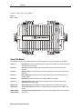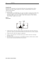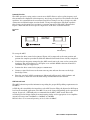
1
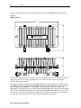
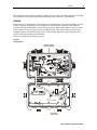
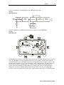
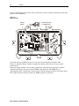
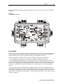
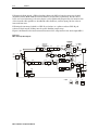
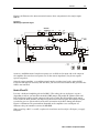
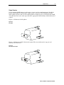
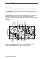
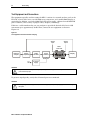
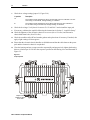
Bench Testing
4-3
Measuring Forward Gain
This subsection provides instructions for measuring the full gain and the operational gain and
flatness of the MB*/*.
To measure the full gain of the amplifier:
1
Determine whether the power-supply jumper (J1) is positioned for LO or HI operation.
2
Connect the MB*/* to the test equipment as illustrated in Figure 4-1 and apply power.
3
Verify that the dc voltage is 24 V ± 0.4 V and re-install the input pad.
4
Apply the sweep signal and adjust test equipment as needed.
5
Select manual gain by placing the drive control select jumper in the MAN position and turn
the MANUAL LEVEL control (Figure 2-15) fully clockwise.
6
Measure the gain at mixed forward frequency using the procedure outlined in the operator
manual provided with the test equipment in use.
To correct this number, add the insertion loss of the SSP-PIN power combiner (0.5 dB at 550
MHz, 0.6 dB at 750 MHz, or 0.7 dB at 870 MHz), the loss of the cable simulator at mixed
forward frequency, and the loss of the cable equalizer (1.0 dB), if it is installed.
Example
The test equipment indicates a measured gain of 12.5 dB with an MB75S/* and the cable
simulator is set to 20 dB.
0.6 dB (power combiner)
+ 1.0 dB (cable equalizer)
+ 20.0 dB (cable simulator)
+ 12.5 dB (measured gain).
34.1 dB (unit gain).
The result must meet advertised specifications for the unit.
The operational gain of the MB*/* provides reduced gain capability. This enables the unit to
operate in the proper region of the Bode board when it is controlled by the ADU or TDU drive
units.
MB*/* Installation and Operation Manual