1
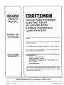
MODEL NO.
917.257480
Caution:
Read and follow
all Safety Rules
and Instructions
Before Operating
This Equipment
18.0 HP TWIN CYLIN
ELECTRIC START
" OWER DECK
5 SPEE
TRANS_LE
LAWN TRACTOR
• Assembly
• Operation
, Maintenance
• Service and Adjustment
• Repair Parts
Sears, Roebuck and Co., Chicago, IL 60684 U.S.A.
,
i=
,i,
, i,
i,i
i
i,H,,llll
SAFETY RULES
CAUTION; ALWAYS DISCONNECT SPARK PLUGWIRE AND PLACE WIRE WHERE IT CANNOT CONTACT SPARK
PLUG TO PREVENT ACCIDENTAL STARTING WHEN SETTING-UP, TRANSPORTING, ADJUSTING OR MAKING
REPAIRS_
IMPORTANT
SAFETY STANDARDS REQUIRE OPERATOR PRESENCE CONTROLS TO MINIMIZE THE RISK OF INJURY. YOUR UNIT IS EQUIPPED WITH SUCH
CONTROLS, DO NOT ATTEMPT TO DEFEAT THE FUNCTION OF THE OPERATOR PRESENCE CONTROLS UNDER ANY CIRCUMSTANCES.
TRAINING:
•
•
•
•
Know the controls and how to stop quickly. Read this owner's
manual and instructions furnished with attachments.
Do not altew children to operate the machine Do not allow
adults to operate it without proper instruction.
Do not carry passengers Do not mow when children and
others are around.
Do not attempt to operate your vehicle or mower when not in
the driver's seat.
Always get on or off your vehicle from the operator's left hand
side.
The vehicle and attachments should be stopped and inspected for damage after striking a foreign object, and the
damage should be repaired before restarting and operating
the equipment
•
•
•
•
•
•
PREPARATION:
•
•
.
•
Always wear substantial footwear_ Do not wear loose fitting
cloth|ng that could get caught in moving parts
Clear the work area of objects (wire, rocks, etc ) which might
be picked up and thrown.
Disengage all attachment clutches before attempting to start
the engine
Handle gasoline with care - it is highly flammable
Use approved gasoline containers°
Never removethe fuel cap of the fuel tank or add gasoline
to a running or hot engine or an engine that has not been
allowed to cool for several minutes after running_ Never
fill tank indoors Always clean up spilled gasoline°
Open doors if the engine is run in the garage oexhaust
fumes are dangerous Do not run the engine indoors,
Do not operate the mower without the entire grass catcher,
on mowers so equipped, or the deflector shield in place.
OPERATION:
•
•
•
•
•
.
.
•
•
•
•
•
•
Keep your eyes and mind on your vehicle, mower, and the
area being cut. Do not let other interests distract you
Disengage power to attachments and stop the engine before
leaving the operator's position,
Disengage power to mower, stop the engine, and disconnect
spark plug wire(s) from spark plug(s) before cleaning, making
an adjustment, or repair. Be careful to avo_id touching hot
muffler or engine components.
Disengage power to attachments when transporting or not in
use.
Take all possible precautions when leaving the vehicle unattended. Disengage the power take-off, lower the attachments, shift into neutral, set the parking brake, stop the
engine, and remove the key.
Do not stop or start suddenly when going uphill or downhill
Mow up and down the face of slopes (not greater than 15°),
never across the face.
Reduce speed on slopes and make turns gradually to pr event
tipping or loss of control. Exercise extreme caution when
changing direction on slopes.
While going up or down slopes, place gearshift control lever
in 1st gear position to negotiate the slope without stopping
Never mow in wet or slippery grass, when traction is unsure,
or at a speed which could cause a skid.
Stay alert for holes in the terrain and other hidden hazards.
Keep away from drop-offs
Do not drive too close to creeks, ditches, and public highways,
Exercise special care when mowing around fixed objects in
order to prevent the blades from striking them. Never deliberately run vehicle or mower into or over any foreign objects_
Never shift gears until vehicle comes to a stop
Never place hands or feet under the mower, in discharge
chute, Or near any moving parts while vehicle or mower ts
running, Always keep clear of discharge chute.
Use care when pulling loads or using heavy equipment°
Use only approved drawbar hitch points
Limit loads to those you can safely control
Do not turn sharply. Use care when backing.
Use counterweight or wheel weights when suggested in
owner's manual
Watch out for traffic when crossing or near roadways
When using any attachments, never direct discharge of
material toward bystanders nor allow anyone near the vehicle while in operation
Except for ad ustments, do not operate engine if air cleaner
or cover drecty over carburetor a r intake is removed
Removal of such part could create a fire hazard
Do not change the engine governor settings or overspeed
the engine; severe damage or injury may result.
When using the vehicle with mower, proceed as follows:
Mow only in daylight or in good artificial Iight.
Shut the engine off when unclogging chute.
Check the blade mounting bolts for proper tightness at
frequent intervals_
Disengage power to mower before backing up. Do not mow
in reverse unless absolutely necessary and then only after
careful observation of the entire area behind the mower.
MAINTENANCE
°
•
•
•
°
AND STORAGE
Keep the vehicle and attachments in good operating condition, and keep safety devices in place and working
Keep all nuts, botts, and screws tight to be sure the equipment is in safe working condition
Never store the equipment with gasoline in the tank inside a
building where fumes may reach an open flame or spark
Allow the engine to cool before storing in any enclosure,
To reduce fire hazard, keep the engine free of grass, leaves,
or excessive grease. Do not clean product while engine is
running.
Do not operate without a muffler, or tamper with exhaust
system Damaged mufflers or spark arresters could create a
fire hazard_ Inspect periodically and replace if necessary_
Under normal usage the grass catcher bag material is
subject to deterioration and wear. It should be checked
frequently for bag replacemenL Replacement bags should
be checked to ensure compliance
with the original
manufacturer's recommendations or specifications°
!
A
i
_h,_
i llll
IT'
MEANS
ATTENTIONI!!
LOOK
FOR - THIS
SYMBOL
BECOME
TO
POINT
ALERT!!!
YOUR
OUT IMPORTANT
SAFETY
INVOLVED,
SAFETY IS PRECAUTIONS.
I
!
PRODUCT
CONGRATULATIONS
on your purchase of a Sears
Tractor_ tt has been designed, engineered and manu.
factured to give you the best possible dependability and
performance.
Should you experience any problem you cannot easily
remedy, please contact your nearest Sears Service
Center/Departmento
We have competent, well-trained
technicians and the proper tools to service or repair this
unit.
Please read and retain this manual.
The instructions will
enable you to assemble and maintain your unit properly.
Always observe the "SAFETY RULES o
MODEL
NUMBER
SPECIFICATIONS
HORSEPOWER:
18.0
GASOLINE CAPACITY:
2 GALLONS
UNLEADED REGULAR
OIL (3.0 PINTS):
SAE 30 (or 10W-30)
WINTER: SAE 5W-30
SPARK PLUG (GAP.O3OIN.):
CHAMPION RJ-19LM
STD361458
VALVE CLEARANCE:
INTAKE _004- _006IN.
EXHAUST .007 - ,009 IN.
GROUND SPEED:
FORWARD
917_257480
SERIAL
_,IUMBER
Ist .77 MPH
2nd 1A6 MPH
3rd 3,41 MPH
4th 4,34 MPH
5th 5.57 MPH
REVERSE: 1.07 MPH
DATE OF PURCHASE
THE MODELAND SERIAL NUMBERS WILL BE FOUND
ON A PLATE UNDER THE SEAT.
TIRE PRESSURE:
YOU SHOULD RECORD BOTH SERIAL NUMBER AND
DATE OF PURCHASE AND KEEP IN A SAFE PLACE
FOR FUTURE REFERENCE.
MAINTENANCE
AGREEMENT
RESPONSIBILITIES
•
Read and observe the safety rules.
•
Follow a regular schedule in maintaining, caring for and
using your unit.
•
Fellow the instructions under "Maintenance"
"Storage" sections of this owner's manual.
i lU
i nnl,n,,lu
LIMITED ONE YEAR WARRANTY
3 AMPS BATTERY
5 AMPS HEADLIGHTS
BLADE BOLT TORQUE:
30-35 FT, LBS,
In the state of California the above is required by law
(Section 4442 of the California Public Resources Code).
Other states may have simitar laws. Federal laws apply on
federal lands, A spark arrestor for the muffler is available
through your nearest Sears Authorized Service Center
(See REPAIR PARTS section of this manual),
and
nlu
CHARGING SYSTEM:
WARNING: This unit is equipped w!th an internal combustion engine and should not be usea on or near any unim.
proved forest-covered, brush-covered or grass-covered
land unless the engine's exhaust system is equipped with
a spark arrestor meeting applicable local or state laws (if
any), If a spark arrester =sused, it should be maintained in
effective working order by the operator.
A Sears Maintenance Agreement is available on this product. Contact your nearest Sears store for details.
CUSTOMER
FRONT: 14 PSI
REAR: 10 PSI
illl,l,,
i,ll
,
i llllllUllUH
ON ELECTRIC
Hi
ii
,llJ,,,
START RIDING EQUIPMENT
For one year from date of purchase, when this tiding equipment is maintained, lubricated, and tuned up according to the
operating and maintenance instructions in the owner's manual, Sears wiU repair free of charge any defect in material or
workmanship.
This Warranty does not cover:
•
3]re replacement or repair caused by punctures from outside objects (such as nails, thorns, stumps, or glass)
Repairs necessary because of operator abuse or negligence, including the failure to maintiain the equipment according to
the instructions contained in the owner's manual,
.
Riding equipment used for commerclal or rental purposes.
FULL 90 DAY WARRANTY
ON BATTERY
For 90 days from date of purchase, if any battery included with this tiding equipment proves defective in material or workmanship
and our testing determines the battery will not hold a charge, Sears witl replace the battery at no charge.
WARRANTY SERVICE IS AVAILABLE BY CONTACTING THE NEAREST SEARS SERVICE CENTER/DEPARTMENT IN THE
UNITED STATES. THIS WARRANTY APPLIES ONLY WHILE THIS PRODUCT iS IN USE iN 3"HEUNITED STATES
This Warranty gives you specific _egalrights, and you may also have other rights which vary from state to state.
SEARS, ROEBUCK AND CO. D/731CR-W SEARS TOWER, CHICAGO, IL 60684
3
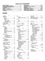
TABLE OF CONTENTS
OPERATION ...........................................................
MAINTENANCE ......................................................
SERVICE AND ADJUSTMENTS ............................
STORAGE ....................................................................
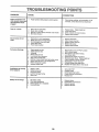
TROUBLESHOOTING ............................................
REPAIR PARTS - TRACTOR .................................
REPAIR PARTS - ENGINE .....................................
PARTS ORDERING/SERVICE ................... BACK
SAFETY RULES ............................................................
2
PRODUCT SPECIFICATIONS ....................................... 3
CUSTOMER RESPONSIBILITIES ................................. 3
WARRANTY ...................................................................
3
TABLE OF CONTENTS .................................................
4
INDEX .............................................................................
4
TRACTOR ACCESSORIES ........................................... 5
ASSEMBLY ................................................................
7-9
10-13
14-17
18-25
26
27-28
30-43
44-49
PAGE
INDEX
Adjustments;
Brake ...................................................
21
Carburetor ...........................................
25
Mower
Front+To*Back ....................................
19
Side-To-Side .................................
18
Throttle Control Cable ......................
24
Air Filter, Engine ...............................................
16
Air Screen, Engine ......................................
16
Assembly .......................................................
7-9
B
Battery:
Charging ..................................................
8
Cleaning .............................................! 6
Installation ..................................................
9
Levels ................................................
8,16
Preparation .................................................
8
Starting with Weak Battery ............22
Storage .....................................................
26
Terminals ................................................
t6
Beit:
Motion Drive
Removal/Replacement
Mower Blade Drive
Removal/Replacement
Blade:
................
21
.................
20
Sharpening ...............................................
15
Replacement ......................................
15
Brake Adjustment ......................................
21
C
Carburetor Adjustment ......................... 25
Controls, Tractor. .........................................
10
Cutting Height, Mower .............................11
E
Electrical:
Interlocks and Relays ........................
23
Schematic ...........................................
29
P
F
Filter:
Air Filter ..................................................
16
Air' Filter Foam Pre-Cleaner ............
16
Fuel .........................................................
17
Fuel:
Type ........................................................
12
Storage
26
Fuse ......................................................................
23
H
....................................................
Hood Removal/Installation
.......................
23
L
Leveling Mower Deck ..................... 18-19
Lubrication:
Chart ...........................................................
14
M
Maintenance ........................................14-17
Air Filter .......................................... 16
Air FUter Foam Pre+Cleaner ..............
16
Air Screen, Engine ...........................
16
Battery ......................................................
16
Blade .........................................................
15
Cooling Fins, Engine ..........................
17
Engine Oil ...........................................
16
Fuel Filter ....................................................
17
Lubrication Chart .................................
14
Schedule ............................................14
Spark Plugs ..............................................
17
Tire Care ......................................
8,15,22
Mower:
Adjustment, Front-to-Back ...............
19
Adjustment, Side4o-Side ...............15
Blade Sharpening ..............................
15
Blade Replacement ..........................15
Cutting Height ........................................
11
lnstaUation ............................................
18
Operation .............................................
12
Removal .................................................
18
Mowing Tips
13
Muffler r,
t7
Parking Brake ..............................................
10-11
Parts Bag .....................................................
6
Parts, RepiacementJRepalr,.............
30-49
ProductSpecifications...................................
3
R
Repair Parts .........................................
30-49
S
Safety Rules ................................................2
Seat
.............................
...........................................
Removal/Replacement
............2t
Mower Blade Drlve Belt
RemovaltReplacement
..............20
Mower Adjustment
Front- to+Back
19
Side*to-Side .....................................
18
Mower Removal ..............................18
Tire Care ........................................
8,15,22
Slope Guide Sheet ............................ 51
Spark Plugs ..................................................
17
Specifications ...............................................
3
Starting the Engine .......................... 12-13
Steering Wheel ........................................
7,22
Stopping the Tractor ....................................
11
Storage .................................................... 26
T
Throttle Control Cable
Adjustment ..................................... 24
Tires ........................................................
8,15,22
....................
..............................................
Cooling Fins, Engine ......................17
Oil Change ...................................... 16
Oil Level
12,16
...........................
.....................
W
.......................................................
Oil:
Cold Weather Conditions ........12,16
Engine .......................................................
16
Storage .....................................................
26
Operation
10-13
Oper atlng Mower ......................................12
Options:
Acces sories ...................................... 5
Spark Arrester ...................................
3,34
....................................
4
..........................................
O
Warranty
Wiring Diagram
Wiring Schematic
.........................................................
Spark Arrester +.............................3,34
..................................................
Oil Type ......................................................
16
Preparation ........................................12
Repair Parts
44-49
Starting ...................................................
13
Storage .......................................... 26
.............
Trouble Shooting Chart ....................27+28
Transaxle:
Repair Parts .............................. 42-43
....................................................
Wiring Diagram ......................................
30
Engine:
Air Fitter ....................................................
16
Air Fitter Foam Pre-Cleaner, ......... 16
Air Screen
16
8
Service and Adjustments .....................
18-25
Carburetor. ..............................................
25
Fuse ........................................................
23
Hood Removal/installation
.......... 23
Motion Drive Belt
3
A
Accessories ...................................................
5
30
..................................... 29
ACCESSORIES
ANDATTACH
...................................
ENT$
=
ill
These accessories and attachments were available when the unit was purchased They are also available at most Sears retail outlets,
catalog and service centers Most Sears stores can order these items for you when you provide the model number of your tractor
MAINTENANCE
ENGINE
SPARK PLUG
MUFFLER
AIR FILTER
GAS CAN
ENGINE OIL
STABIL_ZER
BLADES
BELTS
PERFORMANCE
Sears offers a wide variety of attachments that fit your vehicle. Many of these are listed below with brief explanations of how they
can help you. This list was current at the time of publication; however, it may change in future years - more attachments may be added,
changes may be made in these attachments, or some may no longer be available or fit your model
Contact your nearest Sears
store for the accessories
and attachments
that are available for your unit.
Most of these attachments
attaching and detaching
do not require additional hitches or conversion kits (those that do are indicated)
PERMANEX BAGGER Iets you col(ect grass clippings and
leaves for a healthier, heater tooking lawn
Two Permanex
containers hold 30-gallon plastic bags
LAWN SWEEPERS
let you collect grass clippings and leaves
LAWN VAOS for powerful collections of heavy grass clippings
and leaves Wand attachment to pick up debris in hard-to-reach
praces
CARTS make hauling easy
Variety of sizes available.
ROLLER for smoother lawn surface.
36-inch wide, 18 inch
diameterwater-tightdrumholdsupto3901bs
of weight. Rounded
edges prevent harm to turf Adjustable scraper automatically
cleans drum
SPREADER/SEEDERS
make seeding, fertilizing, and weed killing easy, Broadcast spreaders are also useful for granular deicers and sand
CORING AERATOR takes small plugs out of soil to allow moisture and nutrients to reach grass roots
36-inch swath
24
hardened steel coring tips. 150 lb capacity weight trayr
AERATOR promotes deep root growth for a healthy tawn Tapered 2 5" steel spikes mounted on 10-in diameter discs puncture holes in se{t at dose intervals to Iet moisture soak in Steel
weight tray for increased penetration
DETHATCHER loosens soil and flips thatch and matted leaves to
lawn surface for easy pick up Twenty spring tine teeth Useful
to prepare bare areas for seeding
Available for front or rear
mounting
SPRAYERS use 12-volt DC electric motor that connects to the
tractor battery or other 12-volt source
includes booms for
automatic spraying when puIling, and hand held wand for spot
spraying
Wand has adjustable spray pattern
For appIying
herbicides, insecticides, fungicides, and liquid fertilizers
and are designed for easy
SNOW BLADE for snow removal only. 14-inch high, 42-inch
wide blade clears 38 inch path when angled left or right_ Raises,
lowers with side lever. Adjustable skids; replaceable, reversible
scraper bar (Use with tire chains, wheel weights, or rear drawbar
weight .)
SNOWTHROWER has 40-inch swath. Drum-type auger handles
powdery and wet/heavy snow.. Mounts easily with simple pin
arrangement Discharge chute adjusts from tractor seat 6-inch
d_ameter spout discharges snow 10 to 50 feet. Lift controlled at
tractor seat (Use with chains, wheel weights, or rear drawbar
weight)
TIRE CHAINS are heavy duty; closely spaced extra-large cross
finks give smooth ride, outstanding traction.
WHEEL WEIGHTS for rear wheels provide needed traction for
snow removal or dozing heavy materials. In pairs.. (30 Ibs. each_)
TRACTOR CAB has heavy duty vinyl fabric over tubular steel
frame, ABS plastic top; clear plastic windshield offers 360 degree
visibility. Hinged metal doors with catch. Keeps operator warm
and dry. Remove vinyl and windshields for use as sun protector
in summer
Optional accessories for tractor cab: tinted/tempered solid safety
glass windshield with hand operated wiper; 12-volt amber caution
light for mounting on cab tep r
TRACTOR COVER protects tractor from weather
Made of
Evolution 3 fabric (water-repellent, extremely breathable, iight
weight, soft, non-abrasive, pliable in all temperatures, durable,
stain/tear/puncture resistant, wilt not shrink or stretch)
1iris=
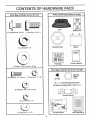
CONTENTS
OF HARDWARE
= ===ll
Hrn,
--,11
, ==1
nu =,,,,_
Parts packed separately in carton
Parts Bag contents shown full size
,i
PACK
H=i,===,,
iiirt
= = ,ram
,,,
n
Seat
Battery acid
(1) Shoulder' Bolt 5/16-18
(1) Hex Bolt 1/2-13 x 1
(1) Lockwasher
(1) Washer
t/2
Steering Wheel
Battery
Parts Bag
Owner's Manual
17/32 x 1-3/16 x 12 Ga,
inn, nn
....................
@
Parts bag contents not shown full size
(2) Keys
G
(2) Washers
Wheel
Steering
Insert
(2) Hex Nuts 1/4- 20
(2) Hex BoLts 1/4- 20 x3/4
(2) Battery Carriage Bolts 1/4-20 x 7-1/2
9/32 x 5/8 x 16 Ga,
Terminal Guard
•
(2) Lockwashers
=
= uun
1/4
H HIH,,
(2) Wing Nuts 1t4 - 20
150 Slope Sheet
6
Battery Caps
and Instructions
t
TOOLS
REQUIRED
FOR ASSEMBLY
A socket wrench set will make assembly easier+ Standard
wrench sizes are listed°
(1) 7/16" wrench
(1) Tire pressure gauge
(2) 9/16" wrenches
(1) Screwdriver
(1) 1/2" wrench
(1) Utility knife
INSERT
HEX LOCKNUT
(1) 3/4" wrench
When right and left hand is mentioned in this manual, it
means when you are in the operating position (seated behind the steering wheel)+
STEERING
TO REMOVE
UNPACK
Remove all loose parts from carton (See page 6),
•
Cut, from top to bottom, all four corners of carton and
lay panels flat+
STEERING
;
Attach steering wheel before rolling tractor off skid,
STEERING
ATTACH
STEERING
WHEEL
_
WHEEL ADPATER
__-
(See Fig. 1)
•
Remove t/2-20 hex nut and large flat washer from
steering column°
•
Position front wheels of the tractor so they are pointing
straight forward
•
I
t
Position steering wheel so cross bars are horizontal
(left to right) and slide onto adapter°
ti
_+
/
I
_
r
_
t,"
I/t
_t /
\"
,
]
zt/
•
Assemble large flat washer and 1/2+20 hex nut and
tighten securely,
•
Snap insert into center of steering wheel,
•
Remove protective plastic from tractor hood+
BEFORE
WHEEL
CARTON
•
•
j
UNIT FROM CARTON
ROLLING
II/
FIG. 1
UNIT OFF SKID
(See Fig. 6)
IMPORTANT:
CHECK
FOR AND REMOVE
ANY
STAPLES IN SKiD THAT MAY PUNC+
TURE TIRES WHERE UNIT IS TO ROLL
OFF SKID+
•
Raise attachment lift lever to its higlnest position,
•
Release parking
pedal_
•
Roll unit backwards off skid
brake by depressing
clutch/brake
7
,
ii
,i
iii,
iiii ,i,,
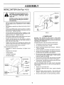
HOW TO SET UP YOUR TRACTOR
INSTALL
PREPARE
Adjust seat before tightening adjustment bolt.
BATTERY
(See Fig, 2)
CAUTION: Wear eye and face shield=
Wash hands or clothing Immediately if
accldentallyin contactwith battery acid.
Do not smoke. Fumes from charged
battery acid are explosive°
Read the instructions included with the
battery vent caps. Always wear gloves,
clothing and goggles to protect your
hands, skin and eyes.
SEAT (See Fig. 3)
•
Remove cardboard packing on seat pan.
°
Ptace seat on pan and assemble shoulder bolt
•
Assemble adjustment bolt, Iockwasher and flat washer
loosely, Do not tighten,
•
Tighten shoulder bolt securely.
•
Lower seat into operating position and sit on seal
•
Slide seat until a comfortable position is reached
which allows you to press clutch/brake pedal all the
way down (See Fig. 6).
•
Get off seat without moving its adjusted position.
•
Raise seat and tighten adjustment bolt securely.
SEAT
Your unit has a battery charging system which is sufficient
for normal use. However, periodic charging of the battery
with an automotive charger will extend its life
•
See instructions packed with vent caps in parts bag.
•
Fill battery with acid Fill each cell until it reaches the
bottom of the vent wells, Do not overfill
•
Allow battery to stand and settle for at least thirty
minutes. After standing, check the level of acid_ If
below the vent wells, add more acid until the correct
fevel is reached.
SEAT PAN
SHOULDER
BOLT
While battery isstanding (after adding acid) and later, while
battery is being charged, cominue with assembly of unit.
•
. FLAT WASHER
To maximize the life of your battery, it is necessary that
the battery be charged before use, Use a 12 volt battery
charger, Charge battery at a rate of 6 amperes for 1
hour. Observe all safety precautions required for battery charging, Failureto charge battery can result in a
shortened battery tife_
CHECK
.
Check the acid level after the battery is charged, if the
acid has fallen below the correct level, add distilled or
iron free water.
The ti_es on your unit were overinflated at the factory for
shipping purposes. Correct tire pressure is important for
best cutting performance,
•
install the vent caps to cover the vent welts_ Wash the
top of the battery with water to remove any acid, then
wipe dry.
Check battery case for leakage to make sure that no
damage has occurred in handling.
•
•
Dispose of excess battery acid. Neutralize acid for disposal by adding it to four inches of water in a five gallon
plastic container. Stir with a wooden or plastic paddle
while adding baking soda until the addition of more
soda causes no more foaming,
For best cutting resuits, mower housing should be properly
leveled,
See "TO LEVEL MOWER HOUSING" in the
Service and Adjustments section of this manual
•
Follow instructions on how to install battery.
•
ADJUSTMENT
• LOCKWASHER
BOEr
FIG. 3
TIRE PRESSURE
Reduce tire pressure to PSI shown in "PRODUCT
SPECIFICATIONS" on page 3 of this manual,
CHECK
CHECK
BELTS
DECK LEVELNESS
FOR
PROPER
POSITION
OF ALL
See the figures that are shown for replacing motion and
mower blade drive belts in the Service and Adjustments
section of this manual. Verify that the belts are routed
correctly.
CUT AWAY VIEW
CHECK
BATTERY
CELLACID
LEVEL
FIG. 2
BRAKE
SYSTEM
After you lealn how to oper-ute your tractor, check to see
that the brake is properly adjusted
See "TO ADJUST
BRAKE" in the Service and Adjustments section of this
manuat
8
,
,, i,,,,,,,,
i,
i i
i, i i ,i
,,,,,,.,i,,
ASS
,
INSTALL
, ,,,m, ,,,,, ,,,,, ,,,,,,,,,,,,,
,i
I'lU'"'llll'll"l'H
BATTERY (See Figs. 4 & 5)
WING NUT
CAUTION: Do not short battery terminals. Before installing battery, remove
metal bracelets,
wristwatch
bands,
rings, etc.
_/
TERMINAL
ACCESS
DOOR
Positive terminal must be connected
first to prevent sparking from accidental grounding.
Make sure drain tube is fastened to drain hole in batter'
tray and battery tray is positioned in hole of batter
Support.
•
Place battery in plastic tray, battery terminals to front of
Tractor.
.
First connect RED battery cable to positive (+) battery
terminal with hex bolt, fiat washer, Iockwasher and hex
nut as shown, Tighten securely
TERMINAL
GUARD
KEY
HOLE
FIG. 5
Connect BLACK grounding cable to negative (-) battery terminal with remaining hex bolt, fiat washer, lockwasher and hex nut. Tighten securely,
•
Slide the two battery bolts through the terminal guard
and start the wing nuts onto the threads
•
Position terminal guard over the battery as shown,
lower bolts into key holes and slide square shafts of
bolts into slots of key holes
•
Tighten wing nuts by hand making sure battery bolts
remain in slots of the key holes in the battery support.
Be sure terminal access doors are closed
•
Use terminal access doors for:
•
Inspection for secure connections
ware)
•
Inspection for corrosion
•
Testing battery
•
Jumping (if required).
•
Periodic charging.
..:\
BATTERY
:"
_
o,
/
TIVE)
CABLE
BATTERY
TRAY
_
(NEGATIVE)
CABLE
DRAIN TUBE
FIG. 4
CHECKLIST:
V" All assembly instructions have been completed
./
No remaining loose parts in carton,
J
Batteryis properly prepared and charged
1 hour at 6 amps),
¢"
Seat is adjusted comfortably and tightened securely.
J
All tires are properly inflated, (Forshipping
the tires were overqnflated at the factory).
V"
Be sure mower deck is properly leveled side-to-side/
front-to-rear for best cutting results° (Tires must be
properly inflated for leveling),
,/
Check mower and drive belts. Be sure they are routed
properly around pulleys and inside all belt keepers,
(Minimum
purposes,
J
°_"
""
PLEASE REVIEW THE FOLLOWING
LOCKWASHER
WAHSER
BLACK
BEFORE YOU OPERATE AND ENJOY YOUR NEW
TRACTOR, WE WISH TO ASSURE THAT YOU RECEIVE
THE BEST PERFORMANCE AND SA TISFACTION FROM
THIS QUALITY PRODUCT_.
(to tighten hard-
NUT
.....
,/'CHECKLIST
Check wiring See that all connections are still secure
and wires are properly clamped,
WHILE LEARNING HOW TO USE YOUR TRACTOR,
PAY EXTRA ATTENTION TO THE FOLLOWING IMPORTANT ITEMS'
/
Engine oil is at proper level.
/
Fuel tank is filled with fresh, clean, regular unteaded
gasoline.
Become familiar with all controls - their location and
function Operate them before you start the engine
J
V"
Be sure brake system is in safe operating condition.
OPERATION
==l
HIIHIHH
=
11l= iHlil
= = =Ill,,=
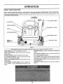
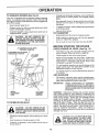
KNOW YOUR TRACTOR
READ
THIS
OWNER'S
MANUAL
AND
SAFETY
RULES
BEFORE
OPERATING
YOUR
TRACTOR
Compare the illustrations with your tractor to familiarize yourself with the locations of various controls and adjustments.
this manual for future reference.
Save
ATTACHMENT
CLUTCH LEVER
IGNITION
SWITCH
IF'i'LEVER
PLUNGER
LIGHT SWITCH
THROTTLE
CONTROL
ATTACHMENT
LIFT LEVER
CHOKE
CLUTCH/BRAKE
PEDAL
PARKING BRAKE
HEIGHT
ADJUSTMENT
KNOB
LEVEL
GEAR SHIFT LEVER
FIG. 6
Sears tractors conform to the safety standards of the American National Standards Institute,_
IGNITION SWITCH: Used for starting and stopping the
engine,
LIFT LEVER PLUNGER: Used to release attachment lift
LIGHT SWITCH: Turns the headlights on and off.
THROTTLE CONTROL: Used for starting and controlling
engine speed,
CHOKE CONTROL: Used for starting a cold engine,
CLUTCH/BRAKE PEDAL: Used for clutching and braking
the tractor and starting the engine,
HEIGHT ADJUSTMENT KNOB: Used to adjust the mower
cutting height.
ATTACHMENT CLUTCH LEVER: Used to engage the
mower blades, or other attachments mounted to your
tractor
lever when changing its position.
ATTACHMENT LIFT LEVER: Used to raise and lower the
mower deck or other attachments mounted to your tractor.
PARKING BRAKE LEVER: Locks Clutch/Brake Pedal into
the brake position.
GEARSHIFT LEVER: Selects the speed and direction of
tractor.
10
=
H nHlll
H
OPERATION
__
xJ_
=mmiNu
your tractor or performing any adjustments or repairs, We recommend wide vision safety
mask for over the spectacles or standard safety glasses, available at Sears Retail or
Catalog stores,
!
HOW TO USE YOUR TRACTOR
TO SET PARKING
BRAKE
IGNITION
(See Fig. 7)
•
Depress clutch/brake pedal into full "BRAKE" position
and hold.
•
Place parking brake lever in "ENGAGED" position and
release pressure from clutch/brake pedal Pedalshould
remain in "BRAKE" position, Make sure parking brake
wilt hold vehicle secure
STOPPING
ATTACHMENT
CLUTCH LEVER
"ENGAGED"
POSITION
(See Fig. 7)
THROTTLE
CONTROL
LEVER
MOWER BLADES •
Move attachment clutch lever to "DISENGAGED"
sition,
"ENGAGED"
POSITION
poPOSmON
GROUND DRIVE •
Depress clutch/brake pedal into full "BRAKE" position,
•
Move gearshift
ENGINE •
lever to "NEUTRAL." position.
"BRAKE"
POSITION
Move throttle control to "SLOW" position,
3EAR
SHIFT
LEVER
"CLUTCH"
POSITION
unauthorized use,
•
/BRAKE
PEDAL "DRIVE"
POSITION
Never use choke to stop engine,
FIG, 7
TO USE THRO'FI'LE
CONTROL
(See Fig. 7)
TO ADJUST
MOWER
CUTTING
HEIGHT
Always operate engine at full throttle
(See Fig. 6)
•
Operating engine at less than full throttle reduces the
battery charging rate and the engine cooling air flow
The cutting height is controlled by turning the height adjustment knob in desired direction
•
Full throttle offers the best bagging and mower performance
•
Turn knob clockwise to raise cutting height,
•
Turn knob counterclockwise
TO MOVE
FORWARD
Thecutting height range is approximately 1-1/4to 3-3/4"
The heights are measured from the ground to the blade tip
with the engine not running These heights are approximate and may vary depending upon soil conditions, height
of grass and types of grass being mowed,
AND BACKWARD
(See Fig. 6)
The direction and speed of movement is controlled by the
gearshift lever
Start tractor with clutch/brake pedal depressed and
gearshift lever in "NEUTRAL" position
•
Move gearshift
lever to desired
to lower cutting height
•
position.
The average lawn should be cut approximately 2-1/2
inches during the cool season and over 3 inches during
hot months For healthier and better looking lawns,
mow often and after moderate growth
For best cutting performance, grass over 6 inches in
height should be mowed twice, Make the first cut
relatively high; the second to desired height
Slowly release clutch/brake pedal to start movement
11
OPERATIO
iiiii
Jl_ I_LI,IILll0
TO OPERATE
MOWER
(See Fig, 8)
Your unit is equipped with an operator presence sensing
switch. Any attempt by the operator to leave the seat with
the eng!ne running and the attachment clutch engaged will
shut off the engine.
•
Select desired height of cut.
•
Engage,mower by slowly moving attachment clutch
lever to ENGAGED position
TO STOP MOWER - Move attachment clutch lever to
"DISENGAGED" position,
iil,,i,ii,,
•
if stopping is absolutely necessary, push clutch/brake
pedal quickly to brake position and engage parking
brake,
•
Move gearshift lever to 1st gear and be sure you have
allowed room for tractor to toil slightly as you restart
movement
•
To restart movement, slowly release parking brake and
clutch/brake pedal
•
Make all turns slowly.
TO TRANSPORT
CAUTION:
DO NOT OPERATE THE
MOWER WITHOUT EITHER THE ENTIRE GRASS CATCHER, ON MOWERS
SO EQUIPPED, OR THE DISCHARGE
GUARD IN PLACE,
°
Raise attachment lift control to highest position
•
When pushing or towing your unit, be sure gearshift
lever is in "NEUTRAL" position,
•
Do not push or' tow unit at more than five (5) MPH
BEFORE STARTING
ATTACHMENT CLUTCH LEVER
"ENGAGED"
POSITION
CHECK
ATTACHMENT
CLUTCH LEVER
"DISENGAGED"
POSITION
LIFT LEVER
PLUNGER
"LOWEST"
POSITION
ENGINE
THE ENGINE
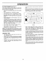
OIL LEVEL (See Fig. 13)
•
The engine in your unit has been shipped, from the
factory, already filled with summer weight oil,
•
Check engine oil with unit on level ground
•
Remove oil fill dipstick and wipe clean, replace and
screw cap tight, wait for a few seconds, remove and
read oil level. If necessary, add oil until "FULL" mark
on dipstick is reached Do not overfill
•
For cold weather operation you shouldchange oil for
easier starting (see "OIL VISCOSITY CHART" in the
Maintenance section of this manual),
•
To change engine oil, see the Maintenance section in
this manual
/
ADD GASOLINE
•
Fill fuel tank. Use fresh, clean, regular unleaded gasoline (Use of leaded gasoline will increase carbon and
lead oxide deposits and reduce valve Iife)_
IMPORTANT:
HEIGHT
ADJUSTMENT
KNOB
LIFT LEVER
"HIGHEST"
POSITION
WARNING:
Experience indicates that alcohol blended
fuels (called gasohol or using ethanol or methanol) can
attract moisture which leads to separation and formation of
acids during storage
Acidic gas can damage the fuel
system of an engine while in storage
To avoid engine
problems, the fuel system should be emptied before storage of 30 days or longer, Drain the gas tank, start the
engine and let it run until the fuel lines and carburetor are
empty. Use fresh fuel next season. See Storage lnstruc_
tions for additional information.
Never use engine or
carburetor cleaner products in the fuel tank or permanent
damage may occur.
FIG. 8
TO OPERATE
ON HILLS
CAUTION;
DO NOT DRIVE UP OR
DOWN HILLS WITH SLOPES GREATER
THAN 15° AND DO NOT DRIVE ACROSS
ANY SLOPE.
•
Choose the slowest speed before starting up or down
hills,
•
Avoid stopping or changing speed on hills
•
If slowing is necessary, move throttle control lever' to
slower position
WHEN OPERATING
IN TEMPERATURES BELOW32°F(0°C), USE FRESH,
CLEAN WINTER GRADE GASOLINE TO
HELP INSURE GOOD COLD WEATHER
STARTING
CAUTION: FILL TO BOTTOM OF GAS
TANK FILLER NECK, DO NOT OVERFILL. WIPE OFF ANY SPILLED OIL OR
FUEL. DO NOT STORE, SPILL OR USE
GASOLINE NEAR AN OPEN FLAME.
12
,,,
,H,
,
m,,,,,,,,
,
==,,,,,,,,,
,,,,,,,,,,,
,,
m,=
OPERATIO
,re,iN,,,,
TO START
ENGINE
,,,,1,,1 ,m,,,,,,,,,,,,,,,
1,1
1, ,m,,,,,,,,,,,,,,,,,,,,,,,,,,,,
The left hand side of mower should be used for trimming.
Drive so that clippings are discharged onto the area
that has been cut. Have the cut area to the right of
the machine, This will result in a more even distribution of clippings and more uniform cutting.
(See Fig. 7)
When starting engine for the first time or if engine has
run out of fuel, it will take extra cranking time to move
fuel from the tank to the engine.
•
Depress the clutch/brake
brake.
•
•
Place gearshift lever in "NEUTRAL" position
Move attachment clutch to "DISENGAGED" position.
•
Pull choke control out to "CHOKE"position
for cold
engine start_ For warm engine start do not use choke
control
,
Move throttle control to midway between "FAST" and
"SLOW" postions.
•
Turn ignition key clockwise to "START" position and
release key as soon as engine starts. Do not run
starter continuously for more than fifteen seconds
per minute. If engine does not start after several
attempts, move throttle control to "FAST" position,
wait a few minutes and try again.
•
•
When engine starts, slowly push choke control in_
Move throttle control to "FAST" position.
•
Allow engine to warm up for a few minutes before
engaging drive or attachment clutch.
pedal and set the parking
FIG. 9
When mowing large areas, start by turning to the
right so that clippings will discharge away from
shrubs, fences, driveways, etc. After one or two
rounds, mow in the opposite direction making left
hand turns until finished (See Fig. 9).
NOTE: If at a high altitude (above 3000 feet) or in cold
temperatures (below 32 ° F), the carburetor fuel mixture
may need to be adjusted for best engine performance.
See "TO ADJUST CARBURETOR" in the Service and
Adjustments section of this manual.
MOWING
•
•
,
--
If grass is extremely tall, it should be mowed twice
to reduce load and possible fire hazard from dried
clippingso Make first cut relatively high; the second
to the desired height.
TIPS
Do not mow grass when it is wet, Wet grass will
plug mower and leave undesirable clumps,, Allow
grass to dry before mowing.
Tire chains cannot be used when the mower housing is attached to unit.
Mower should be properly leveled for best mowing
performance. See TO LEVEL MOWER HOUS NG
in the Service and Adjustments
section of this
manual,
Always operate engine at full throttle when mowing
to assure better mowing performance and proper discharge of material, Regulate ground speed by selecting a low enough speed to give the mower cutting performance as well as the quality of cut desired.
Use the runner on the right hand side of mower as
a guide.
The blade cuts approximately an inch
outside the runner.
When operating attachments, select a ground speed
that will suit the terrain and give best performance of
the attachment being used,
13
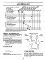
MAUNTENANCE
O
A,°TE°A.OESO.EO0"E
FILL IN DATES
J
T"i Check Brake Operation
R ! Check Tire Pressure
A
Check for Loo,se Fasteners
C
Sharpen/Replace Mower Blades
Lubricate Pivot Points
Check Battery Level/Recharge
'
Clean Battery and Terminals
'........
i .......
J
..............
Check Engine Oil Level
E
Chaje Engine Oil
Clean Air Fiiter?'FoamPro-cleaner
N
Clean Air Screen
.
_
_##_'2
Inspect Muffler/Spark Arrester
N
E
I
Clean Eng!ne Coottng Fins
Replace Spark Plug
......
_2
Replace Air FtIter Paper Cartridge
Replace Fuel Filter
1 - Change more often when operating under a heavy load or in high ambient temperatures
2- Service more often when operating in dirty or dusty conditions
3 - Replace blades more often when mowing _nsandy soil
GENERAL
LUBRICATION
RECOMMENDATIONS
** FRONT
The warranty on this vehicle does not cover items that have
been subjected to operator abuse or negligence°
To
receive fui! value from the warranty, operator must main _
tain unit as instructed in this manual,
BEARING
::::::::::::::::::::::::.
WHEEL
,_._
_
WHEEL
* ATTACHMENT
CLUTCHPIVOT
All adjustments in the Service and Adjustments section of
this manual should be checked at least once each season,
-2
Once a year you should replace the spark plug, clean
or replace air filter, and check blades and belts for
wear_ A new spark plug and clean air filter assure
proper air-fuel mixture and help your engine run better'
andtast longer,
BEFORE
** FRONT
BEARING
Some adjustments will need to be made periodically to
properly maintain your unit,
•
CHART
_
EACH USE
•
Check engine oil level
•
Check brake operation.
•
•
Check tire pressure°
Check for loose fasteners_
J
*
LUBRICATION
Keep unit well lubricated (See "LUBRICATfON
SAE 30 OR 10W30 MOTOR OIL
GENERAL PURPOSE GREASE
REFER TO ENGINE MAINTENANCE
SECTION
IMPORTANT - Do not oil or grease the pivot points which have
special nylon beatings. Viscous lubricants will attract dust and
d_rtthat will shorten the life of the serf-lubricating bearings,If you
feel they must be lubricated, use only a dry, powdered graphite
type iubticant spaHngly_
CHART"),,
14
AINTENANCE
i
,
,,,
,,,
in, u ,.,
ii,uu,,l,uuuu, ll,,,,,,,J,J..u,.,
Jl,ltl
TRACTOR
TO SHARPEN
Always observe safety rules when performing any maintenance.
Care should be taken to keep the blade balanced, An
unbalanced blade will cause excessive vibration and eventual damage to mower and engine,
TIRES
•
The blade can be sharpened with a file or on a grinding
wheel Do not attempt to sharpen while on the mower,
•
To check blade balance, drive a nail into a beam or wail,
Leave about one inch of the straight nail exposed.
Place center hole of blade over the head of the nail. If
blade is batanced, it should remain in a horizontal
position, ff either end of the blade moves downward,
sharpen the heavy end until the blade is balanced.
.
Maintain proper air pressure in all tires (See "PRODUCT SPECIFICATIONS" on page 3 of this manual).
•
Keep tires free of gasoline, oil, or insect control chemicals which can harm rubber.
•
Avoid stumps, stones, deep ruts, sharp objects and
other hazards that may cause tire damage,
BLADE
(See Fig. 11)
CARE
For best results mower blades must be kept sharp° The
blades can be sharpened with a file or on a grinding wheel.
We suggest they be sharpened or replaced after every 25
hours of mowing. Check blades more often if mowing in
sandy conditions.
•
Do not attempt to sharpen blades while they are on the
mower.
•
Replace bent or damaged blades_
BLADE
BLADE
REMOVAL
CENTER
HOLE
(See Fig. 10)
•
Raise mower to highest position to altow access to
blades.
•
Remove hex bolt, lockwasher and fiat washer securing
blade.
•
Install new or resharpened blade with trailing edge up
towards deck as shown°
•
Reassemble hex bolt, lockwasher and flat washer in
exact order as shown.
FIG. 11
•
Tighten bolt securely (30-35 Ft,, Lbs, torque).
IMPORTANT: BLADE BOLT IS GRADE 5 H EATTREATED.
(JACKSHAFT)
ASSEMBLY
FLANGES
TRAILING
UP
HEX BOLT
(GRADE 5)*
*A GRADE 5 HEAT TREATED BOLT
CAN BE IDENTIFIEDBYTHREELINES
ON THE BOLT HEAD AS SHOWN AT
LEFT,
FIG, 10
15
NTENANCE
:u,,iJ,=_w
....................
BATTERY
(See Fig. 12)
e
Your unit has a battery charging system which is sufficient
for normal use. However, periodic charging of the battery
with an automotive charger will extend it's tile.
•
Acid solution level in each battery celt should be even
with bottoms ofvent wells Add only distilled or iron free
water if necessary. Do not overfill.
CUT AWAY VIEW
j
.............
VENTCAP
VENT WELL
Catch oil in a suitable container'.
Remove oil fill dipstick, Be careful not to allow dirt to
enter the engine when changing oil.
Remove drain plug.
After oil has drained completely, replace oil drain plug
and tighten securely.
Refill engine with oil through oil fill dipstick tube. Pour
slowly, Do not overfill For approximate capacity see
Product Specifications on page 3 of this manual
Use gauge on oi! fill dipstick for checking level. Besure
dipstick cap is tightened securely for accurate reading.
Keep oil at "FULL" line on dipstick_
RECOMMENDED
N
r_
_
_
_Z
BA'I-fERY
_ H r_
_ H r_
[_ j_
CELLACID
•
•
FIG, 12
Keep battery and terrninals clean
Keep battery bolts tight
•
Keep vent caps tight and small vent holes in caps open.
SAE VISCOSITY
! I I ! t 1__12j
-20 °
0°
32 °
60 °
,
Clean terminals and battery cable ends with wire brush
until bright.
,
•
Coat terminals with grease or petroleum jelly,
Reinstall battery (See "INSTALL BATTERY" in assembly section of this manual)
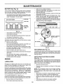
AIR SCREEN
FIG. 13
AIR SCREEN
(See Fig. 13)
The engine air screen must be kept free of dirt and chaff to
prevent engine damage from overheating_ Clean with a
wire brush or compressed air to removed dirt and stubborn
dried gum fibers_
AIR FILTER FOAM PRE-CLEANER
(See Fig. 14)
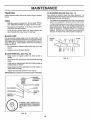
ENGINE
Your engine wiil not run properly and may be damaged by
using a dirty air filter° Clean the foam pre-cleaner element
after every 25 hours of operation, more often if tractor is
used in very dusty, dirty conditions=
•
Remove knobs and cover°
LUBRICATION
Change the oil after the first two hours of operation and
every 25 hours thereafter or at least once a year if the
tractor is not used for 25 hours in one year.
•
Check the crankcase oil level before starting the engine
and after each eight (5) hours of continuous use. Add SAE
30W motor oil or equalivent. Tighten oil fill cap/dipstick
securely each time you check the oil level, SAE 5W-30
Remove foam pre-cleaner
cartridge.
by sliding it off the paper
NOTE: Do not attempt to clean or oil the paper cartridge.
Replace paper cartridge once a year or after every 100
hours of operation, more often if used in very dusty, dirty
conditions,
rnotor oil may be used to make start=ing easier in areas
where temperature is consistently 32 F or Iower_
•
•
•
TO CHANGE ENGINE OIL (See Fig. 13) Determine temperature range expected before oil change,
All oil must meet API service classification SD, SE or SF.
•
Be sure vehicle is on level surface°
•
100°
ENGINE OIL DIPSTICK
AND FILL TUBE
Corrosion and dirt on the battery and terminals can cause
the battery to "leak" power.
•
Remove terminal guard.
•
Disconnect BLACK battery cable first then RED battery cable and remove battery from tractor.
•
Wash battery with solution of fourtablespoons of baking soda to one gallon of water. Be careful not to get
the soda solution into the cells
Rinse the battery with plain water and dry.
80 °
OIL
DRAIN
PLUG
•
Recharge at 6 amperes for 1 hour
TO CLEAN BATTERY AND TERMINALS -
•
GRADES
•
•
Oil will drain more freely when warm.
16
Wash foam pre-cleaner in liquid detergent and water.
Wrap foam pre-cleaner in cloth and squeeze dry.
Lightly coat foam pre-cleaner with de'an engine oil.
Squeeze in towel to remove excess oil, Do not saturate_
Install foam pre-cleaner over paper cartridge.
Reassemble cover and secure with knobs.
== , i=====
MAINTENANCE
= H,H.
MUFFLER
KNOB
Inspect and replace corroded muffler and spark arrester (if
equipped) as it could create a fire hazard and/or damage,
WING NUT
CARTRIDGE
PLATE
SPARK
FOAM
PRE-CLEANER
Replace spark plugs at the beginning of each mowing
season or after every 100 hours of use, whichever comes
first. Spark plug type and gap setting is shown in "PRODUCT SPECIFICATIONS" on page 3 of this manual.
CARTRIDGE
IN-LINE
AIR SCREEN
FUEL FILTER
(See Fig. 16)
Fuelfilter should be replaced once each season_ If fuelfilter
becomes clogged, obstructing fuel flow to carburetor, replacement is required.
"_
BODY
FIGo 14
ENGINE
PLUGS
COOLING
•
With engine cool, remove _ter
sections.
and plug fuel line
•
Place new fuel filter in position in fuel iineo
•
Be sure there are no fuel line leaks and clamps are
properly positioned.
•
Immediately wipe up any spilled gasoline.
FINS (See Fig. 15)
Remove any dust, dirt or oil from engine cooling fins to
prevent engine damage from overheating. Air guide covers
must be removed° Remove side panels and hood (See "TO
REMOVE HOOD AND GRILL ASSMEBLY" in the Service
and Adjustments section of this manual)°
FU EL FILTER
TOP AIR
GUIDE COVER
\
FIG. '16
CLEAN ENGINE
COOLING FINS
CLEANING
•
Clean engine, battery, seat, finish, etc. of all foreign
matter.
•
Keep finished surfaces and wheels free of all gasoline,
oil, etc.
•
Protect painted surfaces with automotive type wax.
We do not recommend using a garden hose to clean your
unit unless the electrical system, muffler, air filter and carburetor are covered to keep water out. Water in engine can
result in a shortened engine tife.
\
AIR GUIDE
COVER{BOTHSIDES)
\
MUFFLER
FIG. 15
17
_L,==
SERVICE AN
11
CAUTION:
=!= 11
llili=
ADJUSTMENTS
=H
BEFORE PERFORMING ANY SERVICE OR ADJUSl"MENTS:
o
Depress clutch!brake pedal fully and set parking
•
•
Place gearshift lever in "NEUTRAL" position.
Place attachment clutch in "DISENGAGED" position.
•
.
•
Turn ignition key "OFF" and remove key=
Make sure the blades and all moving parts have completely stopped.
Disconnect spark plug wire from spark plug and place wire where it cannot come in contact with
plug.
11111
ill
brake.
I,HlIH,I
= I
==,Hi,,,,,i,,,N,,,,,iU,,UU,,,,
TRACTOR
TO REMOVE
MOWER
TO INSTALL
(See Fig, 17)
Mower will be easier to remove from the right side of unit.
.
Remove mower blade drive belt from engine pulley
only !See "TO REPLACE MOWER BLADE DRIVE
BELT through step removing belt from engine pulley).
MOWER
(See Fig. 17)
•
Raise attachment lift lever to its highest position.
•
Slide mower under tractor with discharge guard to right
side of tractor_
•
tnstallparaflet link to front axte and mower with hinge
pins° Secure hinge pins with retainer springs.
install clutch rod in clutch lever and secure with retainer
spring_
•
Remove retainer spring from clutch rod; pull clutch rod
out of clutch lever,
•
•
Pull retainer springs out of rear suspension trunnions.
Remove rear suspension trunnions from lift brackets.
•
•
Pull retainer springs from front hinge pins°
Lower attachment lift lever to lower suspension arms.
Slide trunnions through lift bracket holes and secure
with retainer springs,,
,
Remove hinge pins attaching paraltel link to mower
and front axteo
•
o
Raise lift lever to raise suspension arms. Slide mower
out from under tractor,
•
Roll belt over engine pulley. Make sure belt is inside alt
pulley grooves and inside belt guides.
Raise attachment lift lever to raise mower°
IMPORTANT:
I
CLUTCH
ROD
IF AN ATTACHMENTOTHERTHAN
THE
MOWER IS TO BE MOUNTED TO THE
TRACTOR, THE R.H. AND L.H. SUSPENSION ARMS MUST BE REMOVED
FROM TRACTOR.
CLUTCH
LEVER
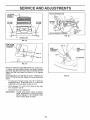
TO LEVEL
RETAINER
SPRINGS
•
Measure height from bottom of deck curl to ground
level at front corners of mower. Distance A should be
the same=
•
If distance "A" needs to be changed, snap out access
hole cover on left side of tractor above footrest.
•
To raise left side of mower, loosen nut"B" and tighten
nut "C".
•
To lower left side of mower, loosen nut "C" and tighten
nut "B".
•
When distance "A" is equal, securely tighten nuts "B"
and "C".
•
Replace access hole cover.
PARALLEL
t=
SPRING
ENGINE
PULLEY
HOUSING
SIDE-TO-SIDE ADJUSTMENT (SEE FIGS_18 AND19) •
Raise attachment lift lever to its highest position.
RETAINER
SPRING
ROD
LIFT
BRACKET
MOWER
Adjust the mower while tractor is parked on level ground or
driveway,
Make sure tires are properly inflated (See
"PRODUCT SPECIFICATIONS" on page 3)_ If tires are
over or under inflated, you will not property adjust your
mower.
PINS
FIGo 17
,4L-"t
SE
CE AND ADJUSTMENTS
i,iLuiu,illU ,i,1,, i i ,
REAR SUSPENSION
ARM
BOTTOM
OFCURL
BOTTOM
OF CURL
GROUND
REARSUSPENSIONTRUNNION
70
LINE
FIG. 20
GROUNDLINE
FIG. 18
SIDE TO SIDE
ADJUSTMENT
TRUNNION
'_._
NUT"E"
REAR
SUSPENSION
TRUNNION
_L_UT
_
REAR
SUSPENSION
ARM
"C"
LIFT BRACKET
.....
.........................
j
NUT "B"
FIG. 19
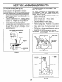
FRONT-TO-BACK ADJUSTMENT(See Figs. 20 and 21) To obtain the best cutting results, the mower housing
should be adjusted so the rear is approximately 3/4 to 7/8"
higher than the front when the mower is in its highest
position,
Check adjustment on right side of tractor_ Measure distance "D" at front and rear flanges of mower housing as
shown.
•
To raise rear of mower, loosen nuts "E" on both rear
suspension arms. Screw both nuts "F" on both rear
suspension arms an equal number of turns.
•
When distance "D" is 3/4 to 7/8" higher at rear than
front, retighten nuts "E".
FIGo21
•
Recheck side-to-side adjustment
IMPORTANT:
WHEN ADJUSTING REAR SUSPENSION TRUNNIONS, ALWAYS ADJUST
BOTH EQUALLY SO MOWER WILL
STAY LEVEL SIDE-TO-SIDE.
19
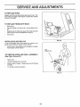
TO ADJUST
MOWER
BLADE
DRIVE
BELT
(See Fig. 22)
IDLER BELT
GUIDE
Your tractor has been manufactured with the ability to
readjust the mower blade drive belt to provide you with
longer belt life.
LH.
MANDREL
ENGINE PULLEY
BELT
With tt_e engine off and the lift lever in the highest
fposition, move clutch lever' up slowly until resistance is
ell
If distance from bottom of slot in dash to cIutch
lever is greater than 4-1/2 inches, adjustment is necessary.
°
Lower the mower deck for easier access,
•
Remove the bolt, nut
reck shaft assembly.
•
Move extension spring from lower to upper' end of
slot in rock shaft assembly and install bolt, nut and
the D-shaped washers (flat side of washers down).
•
Tighten bolt and nut to secure the D-shaped washers (flat side down as shown).
TO REPLACE
(See Figs.
IDLER
EXTENSION
_ING
and D-shaped washers from
MOWER
BLADE
DRIVE
. R,H.
MANDREL
ROCKSHAFT
BELT
EXTENSION
SPRING
22 and 23)
BRAKE
ROD
The mower blade drive belt may be replaced without
tools, Park the tractor on level surface, Engage parking
brake For assistance, there is a belt installation guide
decal on the mower housing,
BELT REMOVAL •
Place attachment clutch in "DISENGAGED" position.
•
Move attachment lift [ever forward to lower mower to
its Iowest posit!on_
•
Rotl belt off engine pulley.
•
Pull belt off both mandrel put!eys
•
Spring belt guide away from idler pulley and pull belt
off idler pulley.
•
SIide belt from under extension spring,
NUT
FIG. 22
ES
BELT INSTALLATION •
Slide belt under extension spring.
•
Place belt around back side and in groove of both
mandrel pulleys.
•
Spring idler belt guide down and place belt around
rear side of idler putley,
•
Roll belt over engine pulley.
•
Make sure belt is in atl pulley grooves and inside atl
belt guides.
FIG. 23
20
ENGINE
SERVICE AN
ADJUSTMENTS
==HH
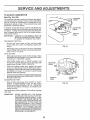
TO ADJUST
BRAKE
TO REPLACE MOTION
Figs. 25 and 26)
(See Fig. 24)
Your unit is equipped with an adjustabte brake system
which is mounted on the right side of the transaxte,
Depress dutch/brake pedal and engage parking brake°
•
Measure distance between brake operating arm and
nut "A" on brake rod.
•
If distance is other than 1-1/2", disengage parking
brake loosen jam nut and turn nut "A" until distance
becomes 1-1/2". Retighten jam nut against nut 'A',
•
Engage parking brake and recheck distance_
•
Road test unit for proper stopping distance as stated
abover Readjust if necessary, If stopping distance is
still greater than six (6) feet in highest gear, further
maintenance is necessary
Contact your nearest
Sears Service Center,
WITH PARKING BRAKE
BELT (See
The tractor drive belt may be replaced without tools
Park the tractor on level area
Engage parking brake,
For assistance, there is a belt installation guide decaf on
bottom side of left footrest,
•
Remove mower (See "TO REMOVE MOWER" in this
section of this manual)_
•
Remove two retainer springs from belt guide bracket
(below transaxle pulley)
Remove bracket_
•
Swing belt guides away from belt
•
Roll belt over top of transaxle pulley.
.
Roll belt over engine pulley and off idler
•
Release parking brake° Pull belt as far as possible
over top of clutch pulley.
•
Reset parking brake.
Pull belt over top of clutch
pulley,
•
Pull belt out up through gearshift lever gate opening
to remove from tractor.
•
install new belt by reversing above procedure,
IMPORTANT:
REPLACE ONLY WITH BELT LISTED
IN THIS MANUAL.
If unit requires more than six (6) feet stopping distance at
high speed in highest gear, then brake must be adjusted.
•
DRIVE
"ENGAGED"
• TRANSAXLE
PULLEY
Z
BELT GUIDE
NUT "A"
JAM NUT
_
.....
..... ,,,,,,,,
OPERATING
ARM
RETAINER
FIG. 24
SPRINGS
FIG, 25
ENGINE
PULLEY
CLUTCH
PULLEY---_..._.
IDLER
/
VIEWED FROM BOTTOM
FIG. 26
21
OF TRACTOR
BELT
CE AND ADJUSTMENTS
.............................................................
TO ADJUST
=
STEERING
WHEEL
WHEEL
CAUTION:
LEAD-ACID
BATTERIES
GENERATE EXPLOSIVE GASES. KEEP
SPARKS,
FLAME AND SMOKING
MATERIALS AWAY FROM BATTERIES.
ALWAYS WEAR EYE PROTECTION
WHEN AROUND BATTERIES.
TOE-IN!CAMBER
The front wheel toe-in and camber are not adjustable on
your unit. If damage has occured to affect the front wheel
toeqn or camber, contact your nearest Sears Service
Center.
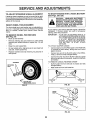
TO REMOVE WHEEL
(See Fig. 27)
If your battery '=stoo weak to start,,the engine, it should be
recharged° If "jumper cables are used for emergency
starting, follow this procedure;
IMPORTANT:
YOUR UNIT IS EQUIPPED WITH A 12
VOLT NEGATIVE GROUNDED SYSTEM.
THE OTHER VEHICLE MUST ALSO BE
A 12 VOLT NEGATIVE GROUNDED
SYSTEM. DO NOT USE YOUR TRACTOR BATTERY TO START OTHER
VEHICLES.
TO ATTACH JUMPER CABLES •
Connect each end of the RED cable to the POSITIVE
(+) terminal of each battery, taking care not to short
against chassis.
•
Connect one end of the BLACK cable to the NEGATIVE (-) terminal of fully charged battery.
FOR REPAIRS
•
Block up axle securely.
•
Remove retaining ring and washers to allow wheel
removal (rear wheel contains a square key - Do not
lose).
•
•
Repair tire and reassemble.
On rear wheels only: align grooves in rear wheel hub
and axle. Insert square key.
•
Replace washers and snap retaining ring securely in
axle groove.
:::::::::::::::::::::::::::
TO START ENGINE WITH A WEAK BATTERY
(See Figs. 28 & 29)
ALIGNMENT
If steering wheel crossbars are not horizontal (left to right)
when wheels are positioned straight forward, remove steeringwhee! and reassemble per instructions in the Assembly
section of this manual.
FRONT
n nmm
•
Connect the other end of the BLACK cable to a panel
bolt on the left side of the chassis, away from fuel tank
and battery_
TO REMOVE CABLES, REVERSE ORDER •
BLACK cable first from left side of chassis and fully
charged battery.
•
RED cable last from both batteries.
WASHERS
RETAINING
RING
!
SQUARE
"POSITIVE....
(*)
KEY
(REARWHEELONLY)
FIG. 27
NEGATIVE"
(9
FIG. 28
FIG. 29
22
TO REPLACE
FUSE
Replace with 30 amp automotive-type plug-in fuse. The
fuse holder is Iocated in the engine compartment, directly
in front of the dash,
TO REPLACE
HEADLIGHT
BULB
•
Raise hood,_
•
Pull bulb holder out of the hole in the backside of the
gdH1
•
Replace bulb in holder and push bulb holder securely
back into the hole in the backside of the grill.
•
Close hood.
INTERLOCKS
FIG. 30
AND RELAYS
Loose or damaged wiring may cause your tractor to run
poorly, stop running or prevent it from starting.
•
Check wiring See electrical wiring diagram in Repair
Parts section of this manual
WIRE
CONNECTION
TO REMOVE HOOD AND GRILL ASSEMBLY
(See Fig's. 30 and 31)
Raise hood,
Unsnap headlight wire connector,
Stand in front of tractor,
brackets,
Grasp hood and lift off hinge
To reinstall, reverse procedure°
FIG. 31
23
TO ADJUST THROTTLE
CONTROL
CABLE
CLAMP SCREW ---__\I
(See Fig. 32)
The throttle control has been preset at the factory and
adjustment should not be necessary, Checkadjustment as
described below before loosening cable If adjustment is
necessary, proceed as follows:
.
With engine not running, move throttle control lever to
"FAST" position°
.
Check that swivel is against side of quarter circle. If it
is not, loosen cable clamp screw and pull cable back
until sw{vel is against quarter circle. Tighten cable
clamp screw securely°
TO ADJUST
CHOKE
CONTROL
(See Fig. 33)
FIG. 32
The choke control has been preset at the factory and adjustment should not be necessary. Check adjustment as
described below before loosening cable If adjustment is
necessary, proceed as follows:
•
With engine not running, move choke control (located
on dash panel) to full "CHOKE" position
•
Remove air' cleaner' cover, filter and spitback plate to
expose carburetor choke (see "AIR FILTER" in maintenance section)
•
•
CHOKECLOSED
f
€
Choke should be closed If it is not, loosen casing
clamp screw and move choke cable until choke is
completely dosed Tighten casing clamp screw securely.
Reassemble air cleaner
LEVER
i CASING
cLAMP
_'_
iSCREW
FIG. 33
24
SERVUCE AND ADJUSTMENTS
TO ADJUST
CARBURETOR
(See Fig. 34 & 35)
The carburetor has been preset at the factory and adjustment should not be necessary. However, minor adjustment
may be required to compensate for differences in fuel,
temperature, altitude or load. If the carburetor does need
adjustment, proceed as follows:
In general, turning the mixture screw in (clockwise) decreases the supply of fuel to the engine giving a leaner fuel/
air mixture Turning the mixture screw out (counterclockwise) increases the supply of fuel to the engine giving a
richer fuel/air mixture.
IMPORTANT:
DAMAGE TO THE NEEDLES AND THE
SEATS IN CARBURETOR MAY RESULT
IF SCREW 1S TURNED IN TOO TIGHT.
PRELIMINARY SETTING •
Be sure you have a clean air filter, and the throttle
control cable and choke are adjusted properly (see
above),
FIG. 34
With engine off turn idle mixture screw in (clockwise)
closing it finger tight and then turn out (counterclockwise) !-1/4 to 1-1/2 turns
FINAL SETTING •
Start engine and allow to warm for five minutes Make
final adjustments with engine running and shift/motion
control lever in "NEUTRAL" position,
•
With throttle control lever in "SLOW" position, hold
throttle lever against idle speed screw and adjust idle
speed screw to obtain 1200 to 1400 RPM
•
While still homing throttle lever against idle speed
screw, turn idle mixture screw in (clockwise) until engine begins to die and then turn out (counterclockwise)
until engine runs rough. Turn screw to a point midway
between those two positions.
•
Continue to hold throttle lever against idle speed screw
and adjust idle speed screw to obtain 900 to 1200 RPM
Release throttle lever.
ACCELERATION
-7
IDLE SPEED
so==
Move throttle control lever from "SLOW" to "FAST"
position tf engine hesitates or dies, turn idle mixture
screw out (counterclockwise) 1/8 turn. Repeat test
and continue to adjust, if necessary, until engine accelerates smoothfy_
IMPORTANT:
)
IDLE MIXTURE
SCREW
THROTTLE
LEVER
TEST-
High speed stop is factory adjusted
may result
(__
FIG. 35
Do not adjust- damage
NEVER TAMPER WITH THE ENGlNE
GOVERNOR, WHICH IS FACTORY SET
FOR PROPER ENGINE SPEED. OVERSPEEDING THE ENGINE ABOVE THE
FACTORY HIGH SPEED SETTING CAN
BE DANGEROUS° IF YOU THINK THE
ENGINE-GOVERNED
HIGH SPEED
NEEDS ADJUSTING, CONTACT YOUR
NEAREST
AUTHORIZED
SERVICE
CENTER, WHICH HAS PROPER EQUIPMENTAND EXPERIENCE TO MAKE ANY
NECESSARY ADJUSTMENTS.
25
LH'J=N
STORAGE
lU,ULULU,J
Immediately prepare your tractor for storage at the end of
the season or if the unit will not be used for 30 days or more.
CAUTION: NEVER STORE THE TRACTOR WITH GASOLLNE IN THE TANK
INSIDE A BUILDING WHERE FUMES
MAY REACH AN OPEN FLAME OR
SPARK. ALLOWTHE ENGINETO COOL
BEFORE STORING IN ANY ENCLOSURE.
TRACTOR
Remove mower from tractor' for winter storage_ When
mower is to be stored for a period of time, clean it thoroughly, remove ail dirt, grease, leaves, etc. Give blades
and underside of housing a good coat of grease or rust
preventative, Store in a clean, dry area
•
Clean entire tractor (See "CLEANING" in the Maintenance section of this manual),
•
.
Drain the fuet tank,
*
Start the engine and let it run until the fuel lines and
carburetor are empty,
.
Never use engine or carburetor cleaner products in the
fuel tank or permanent damage may occur°
Use fresh fuel next season_
•
NOTE: Fuel stabilizer is an acceptable alternative in minimizing the formation of fuel gum deposits during storage_
Add stabilizer to gasoline in fuel tank or storage container.,
Always follow the mix ratio found on stabilizer container.
Run engine at least 10 minutes after adding stabilizer to
allow the stabilizer to reach the carburetor. Do not drain the
gas tank ancJ carburetor if using fuet stabilizer,
ENGINE
OIL
Drain oil (with engine warm) and replace with clean engine
oit. (See "ENGINE in the Maintenance section of this
manual).
Inspect and replace belts, if necessary (See belt replacement instructions in the Service and Adjustments
section of this manual).
Lubricate as shown in the Maintenance section of this
manual
CYLINDERS
•
•
Remove spark plug(s)_
Pour one ounce of oil through spark plug hole(s) into
cylinder,,
•
Be sure that at! nuts, bolts and screws are securely
fastened, Inspect moving parts for damage, breakage
and wear. Replace if necessary.
.
Turn ignitionkey to "START" position for afew seconds
to distribute oil
•
Replace with new spark plug(s).
•
Touch up all rusted or chipped paint surfaces; sand
lightly before painting.
•
BATTERY
•
Fully charge the battery for storage
•
After a period of time in storage, battery may require
recharging.
•
To help prevent corrosion and power leakage during
long periods of storage, battery cables should be disconnected and battery cleaned thoroughly (see "TO
CLEAN BATTERY AND TERMINALS" in the Maintenance section of this manual)°
•
After cleaning, leave cables disconnected and place
cables where they cannot come in contact with battery
terminals,
•
Be sure battery drain tube is securely attached to drain
in battery tray_
ENGINE
FUEL SYSTEM
IMPORTANT;
IT IS IMPORTANT TO PREVENT GUM
DEPOSITS FROM FORMING IN ESSENTIAL FUEL SYSTEM PARTS SUCH AS
CARBURETOR,
FUEL FILTER, FUEL
HOSE, OR TANK DURING STORAGE.
ALSO, EXPERI ENCE INDICATES THAT
ALCOHOL BLENDED FUELS (CALLED
GASOHOL OR USING ETHANOL OR
METHANOL) CAN ATTRACT MOISTU RE
WHICH LEADS TO SEPARATION AND
FORMATION OFACIDS DURING STORAGE ACID!C GAS CAN DAMAGE THE
FUEL SYSTEM OF AN ENGINE WHILE
tN STORAGE
OTHER
•
Do not store gasoline from one season to another.
•
Replace your gasoline can if your can starts to rust.
Rust and/or dirt in your gasoline will cause problems
.
If possible, store your unit indoors and cover it to give
protection from dust and dirL
°
Cover your unit with a suitable protective cover that
does not retain moisture. Do not use plastic Plastic
cannot breathe which allows condensation to form and
will cause your unit to rusL
IMPORTANT:
NEVER COVER TRACTOR WHILE ENGINE AND EXHAUSTAREAS ARE STILL
WARM.
TROUBLESHOOTfNG
PROBLEM
CAUSE
Wilt not start
1.
Out of fuel
2.
3.
4..
5.
6.
7.
Engine not "CHOKED"
Engine flooded
Bad spark plug.
Dirty air fitter
Dirty fuel fitter
Watertn fuel
Hard to start
,, ,,,,,,,I,L,
POINTS
CORRECTION
1
2
3
4.
5
6
7.
properly.
8
9.
_0.
Loose or damaged wiring.
Carburetor out of adjustment.
Engine valves out of adjustment.
8,
9.
10.
1
2
3
4
5
6
7
8
Dirty alr filter.
Bad sparkptug
Weak or dead battery
Dirty fuel filter.
Stale or dirty fuel
Loose or damaged wiring.
Carburetor mJt of adjustment.
Engine valves out of adjustmenL
1
2.
3
4
5
6
7
8.
1
2
3.
4
5.
Clutch/brake pedal not depressed
Attachment crutch Is engaged.
Spark plug wire ls disconnected
Weak or dead battery
Blown fuse
FIll fuel tank
See TO START ENGINE In operation section.
Walt several minutes before attempting to start
Replace spark plug
Clean/replace air ftiter
Replace fuel filter
Drain fuel tank and carburetor, refill tatlk with fresh
gasoline and replace fuel filter
Check ati wiring,
Contact Sears Service Department.
Contact Sears Service Department
Cleanlrepiace air filter
Replace spark plug
Recharge or replace battery
Replace fuel filter
Drain fuel tank and refill with fresh gasoline
Check nit wiring
Contact Sears Service Department
Contact Sears Service Department
,,,,
Engine will not turn over
6
7.
8.
9
1o
1.
2
3.
4
5
6
7
8
9
10.
Corroded batterytermlnals.
Loose or damaged wiring
FauLty ignition switch
Faulty solenold or starter
Faulty operator presence switch (es)
DepressClutch/brake
pedal.
Disengage attachment clutch
Connect wireto spark plug.
Recharge or rep!ace battery
Replace fuse
Clean battery terminals
Check all wiring
Check/replace lgnttion switch.
Check/replace solenoid or starter
Contact Sears Service Department.
Engine clicks but will not
start
1.
2
3,
4.
Weak or dead battery
_orroded battery terminals.
Loose or damagedwlrtng.
Faulty solenoid or starter.
1.
2
3
4
Recharge or replace battery
Clean battery terminals.
Check nit wiring.
Check/replace solenoid or starter
Loss of power
1,
2
3.
4
5
6
7.
8,
9
Cutting too much grass/too fast
Throtfie in "CHOKE" position.
Build-up of grass, leaves and trash under mower
Dirty air filter.
Low olt tevettdtrty etl.
Faulty spark plug
Dirty fuel filter
Stale or dirty fuel
Water tn fuel
1.
2
3
4
5
6
7
8
9
Set in "Higher Cut" position#educe speed.
Adjust throttle control
CIean underside of mower housing
Clean/replace air fitter
Check ol_ levee/change ell
Clean and regap or change spark plug
Replace fuel filter
Draln fuel tank and refill with fresh gasoline.
Drain fuet tank and carburetor, refill tank with fresh
10
11
12
13
t4
15.
Excessive vibration
1
2
3
Spark plug wire loose.
Dirty engine air screen/fins
Dirty/clogged muffler.
Loose or damaged wirlng
Carburetor out of adjustment
Engine valves out of adjustment
Worn, bent or loose blade
Bent blade mandrel
Looseldamaged part(s)
10
11.
12.
gasoline and replace fuel filter
Connect and tlghten spark plug wlre
Clean engine air screenlfins
Cleanirepiace muffler
13
14
15
Check allwirtng.
Contact Sears Service Department
Contact Sears Service Department
t.
2.
3
27
Replace blade Tighten blade bott
Replace blade mandrel
Tighten loose part(s) Replace damaged parts
LESHOOTNNG PORNTS
TBO
±,,H,
11,1
,,,,,
], N=,,
,,,1 ,,
L,
CAUSE
PROBLEM
,11,,
_1,
111,1
CORRECTION
Engine continues to run
when operator leaves seat
with attachment clutch
engaged
1.
Fauity operator-safetypresencecontrolsystem
1_
Check wiring, switches and connections
tf not
corrected, contact Sears Service Department
POOr cUt - uneven
1.
2,
3
4_
Worn, bent or toose blade
Mower deck not level
Build-up of grass, leaves, and trash under mower
Bent blade mandrel
1
2
3.
4,
Repiace biade
Tighten blade bolt
Level mower deck.
Clean underside of mower housing
Replace blade mandrel
1,
2,
3
4
5
Remove obstruction
Adjust mower drive belt
Replace mower drive belt
Replace Idler pulley,
Replace blade mandrel
Mower blades
rotate
wilt not
Poor grass discharge
1
Obstruction
2.
3,
4.
5.
Mower drlve belt out of adjustment
Worn/damaged mower drive belt,
Frozen idler pulley
Frozen biade mandrel.
1
2,
3
4.
Engine speed too slow.
Travel speed too fast.
Wet grass
Mower deck not level.
5,
6
7
8.
9
"_O
,'"""H"H='
In clutch mechanism,
Low/uneven tire air pressure
Worn, bent or loose blade.
Build-up of grass, leaves and trash under mower
Mower drive belt worn or out of sdlustment.
Blades improperly Installed
Improper blades used,
I.
2.
3
4
5
B.
7,
8
9
l0
Place throttle control tn "FAST' position.
Shift to slower speed,
Allow grass to dry before mowing
Level mower deck
Check tires for proper air pressure,
Replace/sharpen ble.de Tighten blade bolt.
Clean underside of mower housing
Replace/adjust mower drive belt
Reinstall blades sharp edge down
Replace with blades itsted in this manual
''"=
Headlight(s) not working
(it so equipped)
Battery will not charge
1.
Switch is "OFF"
1
Turn switch "ON"
2
3
4
5
Bulb(s) burned out,
Faulty light switch,
Loose or damaged wiring.
Blown fuse.
2.
3
4
5
Replace bulb(s)
Check/replace light switch
Check wiring and connections
Replace fuse
1,
2
3.
4
Replace battery.
Check/c_ean all connections
Replace regulator
Replace alternator
1, Bad battery cell(s)
2, Poor cable connections
3
Faulty regulator (if so equipped),
4, Faulty alternator
28
J,,,Juuu,
SUGGESTED
GUIDE FOR SiGHTiNG SLOPES FOR SAFE OPERATION
,,.,w.
ONLY RIDE UP AND DOWN HILL,
NOT ACROSS HILL
.,..,..
SIGHTING
""
1=
0
SIGHT AND HOLD THIS LEVEL WITH
SKY LINE OR TREE.
m
,-r
m
m
/
15° MAX.
i i i i ii
ii i,iiiiii
i
i i
i
greater than 15°), never across the face. Make turns graduOperate your Tractor up and down the face of slopes (not
ally to prevent tipping or loss of control. Exercise extreme
caution when changing direction on slopes,
®
OWNER'S
MANUAL
18.0 HP TWiN CYLI
ELECTRIC START
38"
OWER DECK
5 SPEED TRANSAXLE
LAWN TRACTOR
MODEL NO.
917.257480
Each tractor has its own model number.
number.
Each engine has its own model
The model number for your tractor will be found on the model plate
located under the seat
The model number for your engine will be found on the blower housing,
All parts listed herein may be ordered from any Sears, Roebuck and Co.
Service Centers and most Retail Stores.
WHEN ORDERING REPAIR PARTS, ALWAYS
ING INFORMATION:
HOW TO ORDER
REPAIR PARTS
GIVE THE FOLLOW-
• PRODUCT - LAWN TRACTOR
• MODEL NUMBER - 917,257480
• ENGINE MODEL NUMBER - 422707, TYPE NUMBER 1511-01
° PART NUMBER
• PART DESCRIPTION
Your Sears merchandise has added value when you consider Sears has
service units nationwide staffed with Sears trained technicians_, professional technicians specifically trained to insure that we meet our pledge
to you, we service what we sell
.......................
i i i i i,i i ii l!l,lllllllll
,,llllll
i i i,iH
i i
H,I,,,H,I,,,I_HI
Sears, Roebuck and Co., Chicago, IL 60684 U.S.A.
,, IH
128283X
t1,1690
i
, iiiiH
PRINTED IN USA.