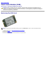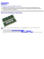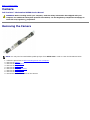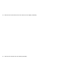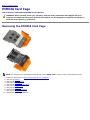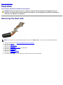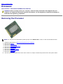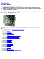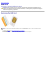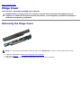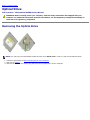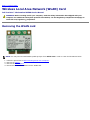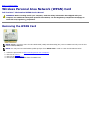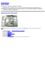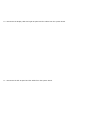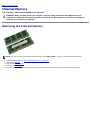
1
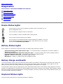
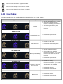
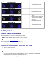
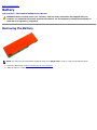
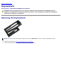
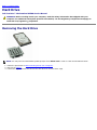
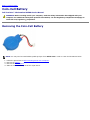
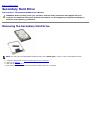
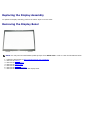
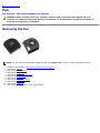
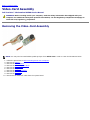
Dell Precision™ Workstation M6500 Service Manual
Working on Your Computer
Removing and Replacing Parts
Specifications
Diagnostics
System Setup
Notes, Cautions, and Warnings
NOTE: A NOTE indicates important information that helps you make better use of your computer.
CAUTION: A CAUTION indicates potential damage to hardware or loss of data if instructions are not
followed.
WARNING: A WARNING indicates a potential for property damage, personal injury, or death.
If you purchased a Dell™ n Series computer, any references in this document to Microsoft® Windows® operating systems are
not applicable.
Information in this document is subject to change without notice.
© 2009-2010 Dell Inc. All rights reserved.
Reproduction of this material in any manner whatsoever without the written permission of Dell Inc. is strictly forbidden.
Trademarks used in this text: Dell, the DELL logo, and Vostroare trademarks of Dell Inc.; Intel, Pentium, Celeron, and Core are either trademarks
or registered trademarks of Intel Corporation; Bluetooth is a registered trademark owned by Bluetooth SIG, Inc. and is used by Dell under license;
Microsoft, Windows, Windows Vista, and the Windows Vista start button are either trademarks or registered trademarks of Microsoft Corporation in
the United States and/or other countries; Adobe, the Adobe logo, and Flash are either registered trademarks or trademarks of Adobe Systems
Incorporated in the United States and/or other countries; ATI FirePro is a trademark of Advanced Micro Devices, Inc.
Other trademarks and trade names may be used in this document to refer to either the entities claiming the marks and names or their products.
Dell Inc. disclaims any proprietary interest in trademarks and trade names other than its own.
March 2010 Rev. A01
Back to Contents Page
Working on Your Computer
Dell Precision™ Workstation M6500 Service Manual
Before Working Inside Your Computer
Recommended Tools
Turning Off Your Computer
After Working Inside Your Computer
Before Working Inside Your Computer
Use the following safety guidelines to help protect your computer from potential damage and to help to ensure your personal
safety. Unless otherwise noted, each procedure included in this document assumes that the following conditions exist:
You have performed the steps in Working on Your Computer.
You have read the safety information that shipped with your computer.
A component can be replaced or—if purchased separately—installed by performing the removal procedure in reverse
order.
WARNING: Before working inside your computer, read the safety information that shipped with your
computer. For additional safety best practices information, see the Regulatory Compliance Homepage at
www.dell.com/regulatory_compliance.
CAUTION: Many repairs may only be done by a certified service technician. You should only perform
troubleshooting and simple repairs as authorized in your product documentation, or as directed by the
online or telephone service and support team. Damage due to servicing that is not authorized by Dell is
not covered by your warranty. Read and follow the safety instructions that came with the product.
CAUTION: To avoid electrostatic discharge, ground yourself by using a wrist grounding strap or by
periodically touching an unpainted metal surface, such as a connector on the back of the computer.
CAUTION: Handle components and cards with care. Do not touch the components or contacts on a card.
Hold a card by its edges or by its metal mounting bracket. Hold a component such as a processor by its
edges, not by its pins.
CAUTION: When you disconnect a cable, pull on its connector or on its pull-tab, not on the cable itself.
Some cables have connectors with locking tabs; if you are disconnecting this type of cable, press in on the
locking tabs before you disconnect the cable. As you pull connectors apart, keep them evenly aligned to
avoid bending any connector pins. Also, before you connect a cable, ensure that both connectors are
correctly oriented and aligned.
NOTE: The color of your computer and certain components may appear differently than shown in this document.
To avoid damaging your computer, perform the following steps before you begin working inside the computer.
1. Ensure that your work surface is flat and clean to prevent the computer cover from being scratched.
2. Turn off your computer (see Turning Off Your Computer).
3. If the computer is connected to a docking device (docked), undock it.
CAUTION: To disconnect a network cable, first unplug the cable from your computer and then unplug the
cable from the network device.
4.
5.
6.
6.
Disconnect all network cables from the computer.
Disconnect your computer and all attached devices from their electrical outlets.
Where applicable, disconnect any adapters from the computer.
Close the display and turn the computer upside-down on a flat work surface.
CAUTION: To avoid damaging the system board, you must remove the main battery before you service the
computer.
7.
8.
9.
10.
Remove the main Battery.
Turn the computer top-side up.
Open the display.
Press the power button to ground the system board.
CAUTION: To guard against electrical shock, always unplug your computer from the electrical outlet before
opening the display.
CAUTION: Before touching anything inside your computer, ground yourself by touching an unpainted metal
surface, such as the metal at the back of the computer. While you work, periodically touch an unpainted
metal surface to dissipate static electricity, which could harm internal components.
11. Remove any installed ExpressCards or Smart Cards from the appropriate slots.
12. Remove the Hard Drive.
Recommended Tools
The procedures in this document may require the following tools:
Small flat-blade screwdriver
#0 Phillips screwdriver
#1 Phillips screwdriver
Small plastic scribe
Flash BIOS update program CD
Turning Off Your Computer
CAUTION: To avoid losing data, save and close all open files and exit all open programs before you turn off
your computer.
1. Shut down the operating system:
In Windows Vista®:
Click Start
Shut Down.
, then click the arrow in the lower-right corner of the Start menu as shown below, and then click
In Windows® XP:
Click Start® Turn Off Computer® Turn Off.
The computer turns off after the operating system shutdown process is complete.
2. Ensure that the computer and all attached devices are turned off. If your computer and attached devices did not
automatically turn off when you shut down your operating system, press and hold the power button for about 4
seconds to turn them off.
After Working Inside Your Computer
After you complete any replacement procedure, ensure you connect any external devices, cards, and cables before turning on
your computer.
CAUTION: To avoid damage to the computer, use only the battery designed for this particular Dell
computer. Do not use batteries designed for other Dell computers.
1. Connect any external devices, such as a port replicator, battery slice, or media base, and replace any cards, such as an
ExpressCard.
2. Connect any telephone or network cables to your computer.
CAUTION: To connect a network cable, first plug the cable into the network device and then plug it into the
computer.
3. Replace the Battery.
4. Connect your computer and all attached devices to their electrical outlets.
5. Turn on your computer.
Back to Contents Page
Back to Contents Page
Removing and Replacing Parts
Dell Precision™ Workstation M6500 Service Manual
ExpressCard
SIM Card
PCMCIA Card
Media Card Battery
Access Panel
Coin-Cell Battery
Hinge Cover Hard Drive
Optical Drive
Secondary Hard Drive
Wireless Local Area Network (WLAN) card
Wireless Wide Area Network (WWAN) Card Wireless Personal Area Network (WPAN) card
Flash Cache Module (FCM)
Keyboard
Memory
Display Assembly
Camera
Palm Rest PCMCIA Card Cage
I/O and IEEE 1394 Board
Heat Sink
Fan
Processor
Video Card Assembly
System Board
Back to Contents Page
Back to Contents Page
Technical Specifications
System Information
Processor
Memory
Video
Audio
Communications
PC Card
ExpressCard
Smart Card
Ports and Connectors
Display
Keyboard
Touchpad
Fingerprint Reader (optional)
Battery
AC Adapter
Physical
Environmental
NOTE: Offerings may vary by region. For more information regarding the configuration of your computer, click Start®
Help and Support and select the option to view information about your computer.
System Information Chipset
Mobile Intel PM55 Chipset
Data bus width
64 bits
DRAM bus width
dual-channel 64 bits
NOTE: You must install memory in pairs
for dual- channel mode to work.
Processor address bus width
36 bits
Flash EPROM
SPI 32 Mbits
Graphics bus
PCI-Express x16 Gen 2 capable
PCI bus
32 bits, 33 MHz
Processor Types
Intel
Intel
Intel
Intel
Intel
Intel
L1 cache
32 KB instruction, 32 KB data cache per
core
L2 cache
Intel Core
Intel Core
Intel Core
Intel Core
Intel Core
Intel Core
— 8 MB
External bus frequency
1333 MHz
Memory Core
Core
Core
Core
Core
Core
i5-520M Dual Core
i5-540M Dual Core
i7-620M Dual Core
i7-740QM Quad Core
i7-840QM Quad Core
i7-940XM Quad Core Extreme
i5-520M Dual Core — 3 MB
i5-540M Dual Core — 3 MB
i7-620M Dual Core — 4 MB
i7-740QM Quad Core — 6 MB
i7-840QM Quad Core — 8 MB
i7-940XM Quad Core Extreme
Type
DDR3
Speed
1333 MHz or 1600 MHz
NOTE: Intel Core i5/i7 dual-core
processors support 1600 MHz and 1333
MHz memory modules, but the memory
will operate at 1067 MHz.
NOTE: Intel Core i7-920XM Quad-Core
processor supports memory frequency up
to 1600 MHz. All other Core i7 Quad-Core
processors support memory frequency up
to 1333 MHz only, even if memory
modules of higher frequency are installed.
Connectors
four SODIMM connectors
NOTE: Computers shipped with dual-core
processors support a maximum of two
memory modules populated in slots A and
B.
Module capacities
1 GB, 2 GB, 4 GB, and 8GB
Minimum memory
2 GB
Maximum memory
8 GB running at 1600 MHz
32 GB running at 1333 MHz
NOTE: When upgrading or replacing memory modules, you must ensure that the
modules are paired and matched in slots A and B first, and then in slots C and D.
Video
Type
discrete
Data bus
PCI-Express x16 Gen 2 capable
Controller and Memory
NVIDIA Quadro FX 3800M (1 GB GDDR3
graphics memory)
NVIDIA Quadro FX 2800M (1 GB GDDR3
graphics memory)
AMD ATI FirePro M7820 (1 GB GDDR5
graphics memory)
Output
15-pin video connector
dual mode DisplayPort connector
Audio
Type
two-channel Intel High Definition Audio
Controller
IDT 92HD81B
Stereo conversion
24-bit (analog-to-digital and digital-toanalog)
Interfaces:
Internal
high definition audio codec
External
microphone connector
stereo headphone/external speaker
connector
Speakers
two 2 W speakers
Internal speaker amplifier
class AB, 2 W Stereo BTL speaker
amplifier
Volume controls
volume up, volume down, and mute
buttons
Communications Network adapter
10/100/1000 Mbps Broadcom NetXtreme
5761E Gigabit Ethernet Controller
Wireless
internal WLAN, WWAN, Bluetooth, and
UWB wireless support (if optional cards
are purchased)
PC Card
NOTE: The PC Card slot is designed only for PC Cards. It does NOT support
ExpressCards.
CardBus controller
Texas Instruments PCI 8412
PC Card connector
one (supports Type I or Type II card)
Cards supported
3.3 V and 5 V
PC Card connector size
80 pins
ExpressCard
NOTE: The ExpressCard slot is designed only for ExpressCards. It does NOT
support PC Cards.
ExpressCard connector
ExpressCard slot (USB and PCI-Express
based interfaces)
Cards supported
34 mm and 54 mm
Smart Card Read/write capabilities
supports ISO-7816-3 (asynchronous and
synchronous Type I and II), ISO7816-12
Cards supported
1.8 V, 3 V, and 5 V
Program technology supported
java cards
Interface speed
9600–115, 200 bps
EMV level
level 1 certified
WHQL certification
PC/SC
Ports and Connectors Audio
microphone connector
stereo headphone/external speaker
connector
Video
15-pin video connector
dual-mode DisplayPort connector
Network adapter
RJ-45 connector
USB
one USB 2.0-compliant connector
one eSATA/USB 2.0-compliant connector
two USB 3.0-compliant connectors
Memory card reader
8-in-1 memory card reader supporting
SD, SDIO, Hi-density SD, Hi-capacity SD,
XD, MS, MS-Pro, MMC, Mini-MMC, and
MMC+ cards
Mini Card
two full-height mini card slots
two half-height mini-card slots
CardBus/PCMCIA slot
supports Type I and Type II cards
IEEE 1394
Texas Instruments PCI 8412 controller,
powered 6-pin connector
E-family docking connector
144-pin docking connector
Display Type (active-matrix TFT)
17 inches, WXGA+, LED
17 inches, WUXGA, LED, RGB, or RGB
edgeto-edge glass
Active area (X/Y)
367.3 mm x 229.5 mm
Dimensions:
Height:
WXGA+/WUXGA
245 mm (9.64 inches)
WUXGA
248 mm (9.76 inches)
Width (WXGA+/WUXGA)
383 mm (15.08 inches)
Diagonal
432 mm (17.00 inches)
Maximum resolutions and brightness:
WXGA+
1440 x 900 at 262 K colors, 220 nits
WUXGA
1920 x 1200 at 262 K colors, 300 nits
WUXGA RGB
1920 x 1200 at 16.7 M colors, 300 nits
Operating angle
0° (closed) to 152°
Refresh rate
60 Hz
Viewing angles:
WXGA+ Horizontal
40°/40°
WXGA+ Vertical
15°/30°
WUXGA Horizontal
60°/60°
WUXGA Vertical
45°/45°
Pixel pitch:
WXGA+
0.191 mm
WUXGA
0.225 mm
Keyboard Number of keys
United States: 101 keys
United Kingdom: 102 keys
Brazil: 104 keys
Japan: 105 keys
Layout
QWERTY/AZERTY/Kanji
Touchpad Resolution:
X axis
57.52 units per mm
Y axis
78.12 units per mm
Active Area:
X axis
80.0 mm (3.14 inches)
Y axis
47.11 mm (1.85 inches)
Fingerprint Reader (Optional)
Type
swipe fingerprint sensor, FIPS 140-2 /
FIPS 201
Battery Type
9-cell "smart" lithium ion (90 W/hr)
Charge time with computer off
approximately 1 hour to 80% capacity
Operating time
battery operating time varies depending
on operating conditions and can be
significantly reduced under certain powerintensive conditions.
Life span
approximately 300 charge/discharge
cycles
Dimensions:
Depth
85 mm (3.35 inches)
Height
23 mm (0.90 inches)
Voltage
11.1 V
Temperature range:
Operating
0 °C to 35 °C (32 °F to 95 °F)
Storage
–40 °C to 65 °C (–40 °F to 149 °F)
Coin-cell battery
3 V CR2032 lithium
AC Adapter Type:
Slim
210 W or 240 W
Standard
210 W
Input voltage
100–240 VAC
Input current (maximum):
Slim
3.5 A
Standard
3.2 A
Input frequency
50 Hz–60 Hz
Output current:
Slim
12.3 A
Standard
10.8 A
Output voltage
19.50 VDC
Dimensions:
Slim (210 W / 240W):
Height
100 mm (3.94 inches)
Width
25.40 mm (1.00 inch)
Depth
200 mm (7.87 inches)
Standard (210 W):
Height
100 mm (3.94 inches)
Width
43 mm (1.70 inches)
Depth
200 mm (7.87 inches)
Temperature range:
Operating
0 °C to 40 °C
(32 °F to 104 °F)
Storage
–40 °C to 65 °C
(–40 °F to 149 °F)
Physical Height
38.5 mm (1.52 inches)
Width
393.0 mm (15.47 inches)
Depth
280.5 mm (11.04 inches)
Weight (minimum)
3.81 kg (8.40 lb)
Environmental Temperature range:
Operating
0 °C to 35 °C (32 °F to 95 °F)
Storage
–40 °C to 65 °C (–40 °F to 149 °F)
Relative humidity (maximum):
Operating
10% to 90% (noncondensing)
Storage
5% to 95% (noncondensing)
Maximum vibration (measured using a
random vibration spectrum that simulates
user environment):
Operating
0.66 Grms (2 Hz–600 Hz)
Storage
1.30 Grms (2 Hz–600 Hz)
Maximum shock (measured with hard
drive in head-parked position and a 2 ms
half-sine pulse):
Operating
142 G
Storage
162 G
Altitude (maximum):
Operating
–15.20 m to 3048 m (–50 to 10,000 ft)
Storage
Airborne contaminant level
Back to Contents Page
–15.20 m to 10,668 m (–50 to 35,000 ft)
G2 or lower as defined by ANSI/ISAS71.04-1985
Back to Contents Page
Diagnostics
Dell Precision™ Workstation M6500 Service Manual
Device Status Lights
Battery Status Lights
Battery Charge and Health
Keyboard Status Lights
LED Error Codes
Dell Diagnostics
Device Status Lights
Turns on when you turn on the computer and blinks when the computer is in a
power management mode.
Turns on when the computer reads or writes data.
Turns on steadily or blinks to indicate battery charge status.
Turns on when wireless networking is enabled.
Turns on when a card with Bluetooth® wireless technology is enabled. To turn off
only the Bluetooth wireless technology function, right-click the icon in the system
tray and select Disable Bluetooth Radio.
Battery Status Lights
If the computer is connected to an electrical outlet, the battery light operates as follows:
Alternately blinking amber light and blue light — An unauthenticated or unsupported, non-Dell AC adapter is
attached to your laptop.
Alternately blinking amber light with steady blue light — Temporary battery failure with AC adapter present.
Constantly blinking amber light — Fatal battery failure with AC adapter present.
Light off — Battery in full charge mode with AC adapter present.
Blue light on — Battery in charge mode with AC adapter present.
Battery Charge and Health
To check the battery charge, press and release the status button on the battery charge gauge to illuminate the charge-level
lights. Each light represents approximately 20 percent of the total battery charge. For example, if four lights are on, the
battery has 80 percent of its charge remaining. If no lights appear, the battery has no charge.
To check battery health using the charge gauge, press and hold the status button on the battery charge gauge for at least 3
seconds. If no lights appear, the battery is in good condition and more than 80 percent of its original charge capacity remains.
Each light represents incremental degradation. If five lights appear, less than 60 percent of the charge capacity remains, and
you should consider replacing the battery.
Keyboard Status Lights
The green lights located above the keyboard indicate the following:
Turns on when the numeric keypad is enabled.
Turns on when the Caps Lock function is enabled.
Turns on when the Scroll Lock function is enabled.
LED Error Codes
The following table shows the possible LED codes that may display in a no-POST situation.
Appearance
Description
ON-FLASH-FLASH
No SODIMMs are
installed
Next Step
1. Install supported memory modules.
2. If memory is already present,
reseat the module(s) one at time in
each slot.
3. Try known good memory from
another computer or replace the
memory.
4. Replace the system board.
FLASH-ON-ON
System board error
1. Reseat the processor.
2. Replace the system board.
3. Replace the processor.
FLASH-ON-FLASH
LCD panel error
1. Reseat the LCD cable.
2. Replace the LCD panel.
3. Replace the video card/system
board.
Memory compatibility
error
1. Install compatible memory
modules.
2. If two modules are installed
remove one and test. Try the other
module in the same slot and test.
Test the other slot with both
modules.
3. Replace the memory.
4. Replace the system board.
Memory is detected
but has errors
1. Reseat the memory.
2. If two modules are installed
remove one and test. Try the other
module in the same slot and test.
Test the other slot with both
modules.
3. Replace the memory.
4. Replace the system board.
OFF-FLASH-OFF
ON-FLASH-ON
OFF-FLASH-FLASH
Modem error
1. Reseat the modem.
2. Replace the modem.
3. Replace the system board.
FLASH-FLASH-FLASH
System board error
1. Replace the system board.
Option ROM error
1. Reseat the device.
2. Replace the device.
3. Replace the system board.
FLASH-FLASH-OFF
OFF-ON-OFF
Storage device error
1. Reseat the hard drive and optical
drive.
2. Test the computer with just the
hard drive and just the optical
drive.
3. Replace the device that is causing
the failure.
4. Replace the system board.
FLASH-FLASH-ON
Video card error
1. Replace the system board.
Dell Diagnostics
When to Use the Dell Diagnostics
It is recommended that you print these procedures before you begin.
NOTE: The Dell Diagnostics software works only on Dell™ computers.
NOTE: The Drivers and Utilities media is optional and may not ship with your computer.
Enter System Setup (see Entering System Setup), review your computer's configuration information, and ensure that the
device you want to test displays in System Setup and is active.
Start the Dell Diagnostics from either your hard drive or from the Drivers and Utilities media.
Starting the Dell Diagnostics From Your Hard Drive
1. Turn on (or restart) your computer.
2. When the DELL logo appears, press <F12> immediately.
NOTE: If you see a message stating that no diagnostics utility partition has been found, run the Dell Diagnostics from
your Drivers and Utilities media.
If you wait too long and the operating system logo appears, continue to wait until you see the Microsoft®
Windows® desktop. Then shut down your computer and try again.
3. When the boot device list appears, highlight Boot to Utility Partition and press <Enter>.
4. When the Dell Diagnostics Main Menu appears, select the test that you want to run.
Starting the Dell Diagnostics From the Drivers and Utilities Media
1. Insert the Drivers and Utilities media.
2. Shut down and restart the computer.
When the DELL logo appears, press <F12> immediately.
If you wait too long and the Windows logo appears, continue to wait until you see the Windows desktop. Then shut
down your computer and try again.
NOTE: The next steps change the boot sequence for one time only. On the next startup, the computer boots according
to the devices specified in the system setup program.
3. When the boot device list appears, highlight Onboard or USB CD-ROM Drive and press <Enter>.
4. Select the Boot from CD-ROM option from the menu that appears and press <Enter>.
5. Type 1 to start the menu and press <Enter> to proceed.
6. Select Run the 32 Bit Dell Diagnostics from the numbered list. If multiple versions are listed, select the version
appropriate for your computer.
7. When the Dell Diagnostics Main Menu appears, select the test you want to run.
Dell Diagnostics Main Menu
1. After the Dell Diagnostics loads and the Main Menu screen appears, click the button for the option you want.
Option
Function Express
Test
Performs a quick test of devices. This test typically takes 10 to 20 minutes and requires no interaction on your
part. Run Express Test first to increase the possibility of tracing the problem quickly.
Extended
Test
Performs a thorough check of devices. This test typically takes 1 hour or more and requires you to answer
questions periodically.
Custom
Test
Tests a specific device. You can customize the tests you want to run.
Symptom Lists the most common symptoms encountered and allows you to select a test based on the symptom of the
Tree
problem you are having.
2. If a problem is encountered during a test, a message appears with an error code and a description of the problem.
Write down the error code and problem description and follow the instructions on the screen.
3. If you run a test from the Custom Test or Symptom Tree option, click the applicable tab described in the following
table for more information.
Tab
Function Results
Displays the results of the test and any error conditions encountered.
Errors
Displays error conditions encountered, error codes, and the problem description.
Help
Describes the test and may indicate requirements for running the test.
Configuration Displays your hardware configuration for the selected device.
The Dell Diagnostics obtains configuration information for all devices from system setup, memory, and
various internal tests, and it displays the information in the device list in the left pane of the screen. The
device list may not display the names of all the components installed on your computer or all devices
attached to your computer.
Parameters
Allows you to customize the test by changing the test settings.
4. When the tests are completed, if you are running the Dell Diagnostics from the Drivers and Utilities media, remove the
media.
5. Close the test screen to return to the Main Menu screen. To exit the Dell Diagnostics and restart the computer, close
the Main Menu screen.
Back to Contents Page
Back to Contents Page
System Setup
Dell Precision™ Workstation M6500 Service Manual
Boot Menu
Navigation Keystrokes
Entering System Setup
System Setup Options
Boot Menu
The boot menu allows you to set a one-time boot sequence without entering system setup. You can also use this procedure
to run the diagnostics on your
1. Turn on (or restart) your computer.
2. When the Dell™ logo appears, press <F12> immediately. The following options appear:
Internal hard drive
CD/DVD/CD-RW Drive
Onboard NIC
BIOS Setup
Diagnostics
3. Select the device from which you want to boot and press <Enter>.
The computer boots to the selected device. The next time you reboot the computer, the previous boot order is restored.
Navigation Keystrokes
Use the following keystrokes to navigate the System Setup screens.
Navigation Keystrokes
Action
Keystroke
Expand and collapse field
<Enter>, left- or right-arrow key
Exit BIOS
<Esc>—Remain in Setup, Save/Exit, Discard/Exit
Change a setting
Left or right-arrow key
Select field to change
<Enter>
Cancel modification
<Esc>
Reset defaults
<Alt><F> or Load Defaults menu option
Entering System Setup
You can enter System Setup using one of the following methods:
Using the boot menu
By pressing <F2>
Boot Menu
1. Turn on (or restart) your computer.
2. When the Dell™ logo appears, press <F12> immediately.
3. Highlight the option to enter System Setup and then press <Enter>
NOTE: Making changes in the boot menu does not make any changes to the boot order stored in the System Setup
program.
<F2>
1. Turn on (or restart) your computer.
2. When the Dell logo appears, press <F2> immediately.
If you are unable to enter System Setup by pressing the <F2> key when the Dell Logo appears, continue to wait until you
see the Windows desktop. Then restart your computer and press <F2> when the keyboard lights first flash.
System Setup Options
The following tables describe the menu options for the System Setup program.
General
Option
Description
This section lists the primary hardware features of your computer. There are no configurable options in this
section.
System
Information
System Information
BIOS Version
Service Tag
Asset Tag
Ownership Tag
Memory Information
Memory Installed
Memory Available
Memory Speed
Memory Channel Mode
Memory Technology
DIMM A Size
DIMM B Size
DIMM C Size
DIMM D Size
Processor Information
Processor Type
Core Count
Processor ID
Current Clock Speed
Minimum Clock Speed
Maximum Clock Speed
Device Information
Primary Hard Drive
Secondary Hard Drive
Fixed Bay Device
System eSATA Device
Dock eSATA Device
Video Controller
Video BIOS Version
Video Memory
Panel Type
Native Resolution
Audio Controller
Wi-Fi Device
Cellular Device
Bluetooth® Device
Wireless USB Device
Battery
Indicates the primary battery status. Also displays the type of AC adapter connected to the computer.
Information
The computer attempts to boot from the sequence of devices specified in this list:
Boot
Sequence
Diskette drive
USB Storage Device
CD/DVD/CD-RW Drive
Internal hard drive
Cardbus NIC
Onboard NIC
This list specifies the order that the BIOS searches for devices while trying to find an operating system to
boot.
To change the boot order, select the device to be changed in the list then click the up/down arrows or use the
keyboard PgUp/PgDn keys to change the boot order of the device.
To remove devices for the boot list, clear the check boxes.
Date/Time
Displays current date and time settings.
System Configuration
Option
Description
NOTE:
The System Configuration group contains options and settings relater to integrated system devices.
(Depending on your computer and installed devices, the items listed in this section may or may not
appear.)
Integrated
NIC
System
Management
Parallel Port
Enables or disables the onboard LAN controller.
Default setting: Enabled w/PXE
This option controls System Management mechanism. The settings are Disabled, Alert Only, and ASF
2.0.
Default setting: Disabled
This option determines how the parallel port on the docking station operates. The settings are Disabled,
AT, PS/2, and ECP.
Default setting: ECP
Serial Port
This option determines how the serial port on the docking station operates. It lets you avoid resource
conflicts between devices by disabling or re-mapping the address of the port. The settings are Disabled,
COM1, COM2, COM3, and COM4.
Default setting: COM1
SATA
Operation
This option configures the operating mode of the internal SATA hard drive controller. The settings are
Disabled, ATA, AHCI, and RAID.
Default setting: RAID
Use the check boxes to enable/disable the following devices:
Miscellaneous
Devices
External USB Port I
Microphone
IEEE 1394
ExpressCard
Precision ON Reader
Module Bay
PC Card
Media Card
eSATA Ports
Default setting: All enabled
Video
Option
Description
Ambient Light
Enabling this feature allows your computer to automatically change the brightness of the display panel
Sensor
based on the amount of light in the surroundings.
LCD
Brightness
This option (represented by a slider bar for On Battery and On AC) sets the panel brightness when the
ambient light sensor is off.
Security
Option
Description
This field lets you set, change, or delete the administrator password. The administrator password enables
several security features when set including:
Admin
Password
Restricts changes to the settings in Setup.
Restricts the boot devices listed in the <F12> Boot Menu to those enabled in the Boot Sequence
field.
Prohibits changes to the owner and asset tags.
Substitutes for the system password if the system prompts for a password during power on.
Successful changes to this password take effect immediately.
If you delete the admin password, the system password is also deleted. Also, the admin password can be
used to delete the hard drive password. For this reason, you cannot set an admin password if a system
password or hard drive is already set. The admin password must be set first if used in conjunction with a
system and/or hard drive password.
System
Password
This field lets you set, change, or delete the system password.
Internal hard drive
PW
This field lets you set, change, or delete the password on the system's internal hard drive. Successful
changes take place immediately and require a system restart. The hard drive password travels with the
hard drive, so the hard drive is protected even when installed in another system.
Password
Bypass
This option lets you bypass the system and internal hard drive password prompts during a system restart or
when resuming from a standby state. Settings are Disabled, Reboot Bypass, Resume Bypass, and
Reboot & Resume Bypass.
The system will always prompt for the set system and internal hard drive password when powered on from
an off state (cold boot).
Default setting: Disabled
Password
Change
This option lets you determine whether changes to the System and hard drive passwords are permitted
when an Admin password is set. Use the check box to allow or disallow changes.
Default setting: Allow Non-Admin Password Changes
This option lets you control whether the Trusted Platform Module (TPM) in the system is enabled and visible
to the operating system. When disabled (check box is empty), the BIOS will not turn on the TPM during
POST. The TPM will be non-functional and invisible to the operating system. When enabled (check box
filled) the BIOS will turn the TPM on during POST so the it can be used by the operating system.
TPM Security
Disabling this option does not change any settings you may have made to the TPM, nor does it delete or
change any information or keys you may have stored there. It simply turns off the TPM so that it cannot be
used. When you re-enable the TPM, it will function exactly as it did before it was disabled.
Once TPM is enabled (check box filled), the available settings are Deactivate, Activate, and Clear.
With the TPM in Deactivate mode, it will not execute any commands that use the resources of the TPM, nor
will it allow any access to stored owner information.
The Clear setting allows the owner's information stored in the TPM to be cleared. Use this to restore the
TPM to its default state if you lose or forget the owner authentication data.
Computrace®
CPU XD
Support
This field lets you activate or disable the BIOS module interface of the optional Computrace software. The
settings are Deactivate, Disable, and Activate.
The Activate and Disable options will permanently activate or disable the feature and no further changes will
be allowed.
This field enables or disables the Execute Disable mode of the processor. Use the check box to enable /
disable this feature.
Default setting: Enabled
This option lets you determine whether changes to the setup option are permitted when an administrator
password is set. If disabled the setup option is locked by the admin password. It cannot be modified unless
setup is unlocked. Use the check boxes to allow / deny access to the Wi-Fi Catcher Changes and / or
Wireless Switch Changes within the system setup.
Non-Admin
Setup
Changes
Performance
Option
Description
Intel® SpeedStep
Use the check box to enable / disable mode for the CPU.
Power Management
Option
Description
Wake on
AC
Use the check box to enable/disable the computer to power up from the off or hibernation state when an AC
adapter is inserted.
Auto On
Time
USB Wake
Support
This field sets the days, if any, when you would like the system to turn on automatically. The settings are
Disabled, Everyday, or Weekdays.
Default setting: Off
Use the check box to enable/disable the ability for USB devices to wake the system from Standby.
This feature is only functional when the AC power adapter is connected. If the AC power adapter is removed
during Standby, the BIOS will remove power from all of the USB ports to conserve battery power.
This field allows the computer to power up from the off state when triggered by a special LAN signal or from
Hibernate state when triggered by a special wireless LAN signal. Wake-up from the Standby state is
unaffected by this setting and must be enabled in the operating system.
Disabled — Do not allow the system to power on when it receives a wake-up signal from the LAN or
wireless LAN.
LAN Only — Allow the system to be powered on by special LAN signals.
WLAN Only — Allow the system to be powered on by special WLAN signals.
LAN or WLAN — Allow the system to be powered on by special LAN or wireless LAN signals.
Wake on
LAN/WLAN
The factory default setting is Off.
Charger
Behavior
This field lets you enable / disable the battery charger. If disabled, the battery will not lose power when the
system is connected to an AC adapter but it will not charge either.
Default setting: Charger Enabled
POST Behavior
Option
Description
Adapter
Warnings
Use the check box to enable/disable the BIOS warning messages when you use certain power adapters. The
BIOS displays these messages if you attempt to use a power adapter that has too little capacity for your
configuration.
Default setting: Enabled
This option lets you choose one of two methods to enable the keypad that is embedded in the internal
keyboard.
Keypad
(Embedded)
Fn Key Only — The keypad is only enabled when you hold down the <Fn> key.
By Num Lk — The keypad is enabled when (1) the Num Lock LED is on and (2) no external keyboard
is attached. Note that the system might not notice immediately when an external keyboard is
detached.
When Setup is running, this field has no effect—Setup works in the Fn Key Only mode.
Default setting: Fn Key Only
Numlock
LED
Use the check box to enable/disable the Num Lock LED when the system boots.
Default setting: Enabled
USB
Emulation
This option defines how the BIOS, in the absence of a USB–aware operating system, handles USB devices.
USB emulation is always enabled during POST. Use the check box to enable/disable this feature.
Default setting: Enabled
This field lets you use the <Scroll Lock> key on an external PS/2 keyboard the same way you use the <Fn>
key on the computer's internal keyboard. Use the check box to enable/disable this feature.
Fn Key
Emulation
USB keyboards cannot emulate the <Fn> key if you are running an ACPI operating system such as
Microsoft® Windows® XP. USB keyboards will only emulate the <Fn> key in non-ACPI mode (e.g., when you
are running in DOS).
Default setting: Enabled
This field can speed up the boot process by bypassing some compatibility steps.
Fast Boot
Minimal — Boot quickly unless the BIOS has been updated, memory changed, or the previous POST
did not complete.
Thorough — Do not skip any steps in the boot process.
Auto — Allow the operating system to control this setting (this works only when the operating system
supports Simple Boot Flag).
Default setting: Minimal
Virtualization Support
Option
Description
Virtualization
This field specifies whether a Virtual Machine Monitor (VMM) can utilize the additional hardware
capabilities provided by Intel® Virtualization Technology. Use the check box to enable/disable this
feature.
Default setting: Disabled.
VT for Direct
I/O
This option specifies whether a Virtual Machine Monitor (VMM) can utilize the additional hardware
capabilities provided by Intel Virtualization Technology for Direct I/O. Use the check box to enable/disable
this feature.
Default setting: Disabled.
Trusted
Execution
This option specifies whether a Measured Virtual Machine Monitor (MVMM) can utilize the additional
hardware capabilities provided by Intel Trusted Execution Technology. The TPM, Virtualization
Technology, and Virtualization Technology for Direct I/O must be enabled to use this feature. Use the
check box to enable/disable this feature.
Default setting: Disabled.
Wireless
Option
Description
Wireless Switch Use the check boxes to determine which wireless devices will be controlled by the wireless switch. The
available options are WWAN, WLAN, Bluetooth®, and Wireless USB.
Wireless
Devices
Use the check boxes to enable / disable the various wireless devices. The available options are Internal
WWAN, Internal WLAN, Internal Bluetooth®, and Wireless USB.
Maintenance
Option
Service Tag
Asset Tag
Description
This field displays your system's Service Tag. If for some reason the Service Tag was not already set,
you would be able to use this field to set it.
If a Service Tag has not been set for this system, the computer will automatically bring up this screen
when users enter the BIOS. You will be prompted to enter the Service Tag.
This field allows you to create a system Asset Tag. The field can only be updated if the Asset Tag is not
already set.
System Logs
Option
Description
BIOS Events
This field allows you to view and clear BIOS power-on self-test (POST) events. It includes the date and
time of the event as well as the LED code.
DellDiag Events
This filed allows you to view the diagnostic results from Dell Diagnostics and PSA. It includes the time
and date, the diagnostic version and the resulting code.
Thermal Events
This field allows you to view and clear thermal events. It includes the date and time as well as the name
of the event.
Power Events
This field allows you to view and clear power events. It includes the date and time of the event as well as
the power state and reason.
Back to Contents Page
Back to Contents Page
Battery
Dell Precision™ Workstation M6500 Service Manual
WARNING: Before working inside your computer, read the safety information that shipped with your
computer. For additional safety best practices information, see the Regulatory Compliance Homepage at
www.dell.com/regulatory_compliance.
Removing the Battery
NOTE: You may need to install Adobe® Flash® Player from Adobe.com in order to view the illustrations below.
1. Follow the procedures in Before Working Inside Your Computer.
2. Slide the latch to release the battery from the computer.
3. Lift the battery up and away from the computer.
Replacing the Battery
To replace the battery, perform the above steps in reverse order.
Back to Contents Page
Back to Contents Page
ExpressCard
Dell Precision™ Workstation M6500 Service Manual
WARNING: Before working inside your computer, read the safety information that shipped with your
computer. For additional safety best practices information, see the Regulatory Compliance Homepage at
www.dell.com/regulatory_compliance.
Removing the ExpressCard
NOTE: You may need to install Adobe® Flash® Player from Adobe.com in order to view the illustrations below.
1. Follow the procedures in Before Working Inside Your Computer.
2. Push in the ExpressCard to release it from its slot on the computer.
3. Pull out the ExpressCard and remove it from the computer.
Replacing the ExpressCard
To replace the ExpressCard, perform the above steps in reverse order.
Back to Contents Page
Back to Contents Page
Hard Drive
Dell Precision™ Workstation M6500 Service Manual
WARNING: Before working inside your computer, read the safety information that shipped with your
computer. For additional safety best practices information, see the Regulatory Compliance Homepage at
www.dell.com/regulatory_compliance.
Removing the Hard Drive
NOTE: You may need to install Adobe® Flash® Player from Adobe.com in order to view the illustrations below.
1. Follow the procedures in Before Working Inside Your Computer.
2. Remove the battery.
3. Loosen the captive screws that secure the hard drive to the hard-drive cage.
4. Pull the release tab to release the hard-drive cage from the computer.
5. Remove the hard-drive cage from the computer.
6. Slide the hard drive away from the computer.
7. Using the black pull-tab, lift the hard drive up and remove it from the computer.
8. Remove the screws that secure the black pull-tab bar to the hard drive.
9. Remove the black pull-tab bar from the hard drive.
Replacing the Hard Drive
To replace the hard drive, perform the above steps in reverse order.
Back to Contents Page
Back to Contents Page
PCMCIA Card
Dell Precision™ Workstation M6500 Service Manual
WARNING: Before working inside your computer, read the safety information that shipped with your
computer. For additional safety best practices information, see the Regulatory Compliance Homepage at
www.dell.com/regulatory_compliance.
Removing the PCMCIA Card
NOTE: You may need to install Adobe® Flash® Player from Adobe.com in order to view the illustrations below.
1. Follow the procedures in Before Working Inside Your Computer.
2. Push the release button twice to release the PCMCIA card from its slot on the computer.
3. Pull the PCMCIA card from the computer.
Replacing the PCMCIA Card
To replace the PCMCIA card, perform the above steps in reverse order.
Back to Contents Page
Back to Contents Page
Coin-Cell Battery
Dell Precision™ Workstation M6500 Service Manual
WARNING: Before working inside your computer, read the safety information that shipped with your
computer. For additional safety best practices information, see the Regulatory Compliance Homepage at
www.dell.com/regulatory_compliance.
Removing the Coin-Cell Battery
NOTE: You may need to install Adobe® Flash® Player from Adobe.com in order to view the illustrations below.
1.
2.
3.
4.
Follow the procedures in Before Working Inside Your Computer.
Remove the battery.
Remove the access panel.
Slide the coin-cell battery out of the mylar sleeve.
5. Disconnect the coin-cell battery cable from the system board and remove it from the computer.
Replacing the Coin-Cell battery
To replace the coin-cell battery, perform the above steps in reverse order.
Back to Contents Page
Back to Contents Page
Hard Drive
Dell Precision™ Workstation M6500 Service Manual
WARNING: Before working inside your computer, read the safety information that shipped with your
computer. For additional safety best practices information, see the Regulatory Compliance Homepage at
www.dell.com/regulatory_compliance.
Removing the Hard Drive
NOTE: You may need to install Adobe® Flash® Player from Adobe.com in order to view the illustrations below.
1. Follow the procedures in Before Working Inside Your Computer.
2. Remove the battery.
3. Loosen the captive screws that secure the hard drive to the hard-drive cage.
4. Pull the release tab to release the hard-drive cage from the computer.
5. Remove the hard-drive cage from the computer.
6. Slide the hard drive away from the computer.
7. Using the black pull-tab, lift the hard drive up and remove it from the computer.
8. Remove the screws that secure the black pull-tab bar to the hard drive.
9. Remove the black pull-tab bar from the hard drive.
Replacing the Hard Drive
To replace the hard drive, perform the above steps in reverse order.
Back to Contents Page
Back to Contents Page
Secondary Hard Drive
Dell Precision™ Workstation M6500 Service Manual
WARNING: Before working inside your computer, read the safety information that shipped with your
computer. For additional safety best practices information, see the Regulatory Compliance Homepage at
www.dell.com/regulatory_compliance.
Removing the Secondary Hard Drive
NOTE: You may need to install Adobe® Flash® Player from Adobe.com in order to view the illustrations below.
1.
2.
3.
4.
Follow the procedures in Before Working Inside Your Computer.
Remove the Battery.
Remove the Access Panel.
Remove the screws that secure the secondary hard drive to the computer.
5. Pull the black tab to lift the hard drive up and away from the computer.
6. Remove the screws on either sides of the hard drive to release the hard-drive bracket from the hard drive.
7. Remove the hard-drive bracket from the hard drive.
8. Remove the hard-drive interposer from the hard drive.
Replacing the Secondary Hard Drive
To replace the secondary hard drive, perform the above steps in reverse order.
Back to Contents Page
Back to Contents Page
Wireless Wide Area Network (WWAN) Card
Dell Precision™ Workstation M6500 Service Manual
WARNING: Before working inside your computer, read the safety information that shipped with your
computer. For additional safety best practices information, see the Regulatory Compliance Homepage at
www.dell.com/regulatory_compliance.
Removing the WWAN card
NOTE: You may need to install Adobe® Flash® Player from Adobe.com in order to view the illustrations below.
1.
2.
3.
4.
Follow the procedures in Before Working Inside Your Computer.
Remove the battery.
Remove the access panel.
Disconnect the antenna cables from the WWAN card.
5. Remove the screw that secures the WWAN card to the system board.
The card pops up at a 45-degree angle.
6. Slide the WWAN card out of the connector on the system board.
Replacing the WWAN Card
To replace the WWAN card, perform the above steps in reverse order.
Back to Contents Page
Back to Contents Page
Flash Cache Module (FCM)
Dell Precision™ Workstation M6500 Service Manual
WARNING: Before working inside your computer, read the safety information that shipped with your
computer. For additional safety best practices information, see the Regulatory Compliance Homepage at
www.dell.com/regulatory_compliance.
Removing the FCM Card
NOTE: You may need to install Adobe® Flash® Player from Adobe.com in order to view the illustrations below.
1.
2.
3.
4.
Follow the procedures in Before Working Inside Your Computer.
Remove the battery.
Remove the access panel.
Remove the screw that secures the FCM card to the system board.
5. Pull the FCM card away from the computer.
Replacing the FCM Card
To replace the FCM card, perform the above steps in reverse order.
Back to Contents Page
Back to Contents Page
Memory
Dell Precision™ Workstation M6500 Service Manual
WARNING: Before working inside your computer, read the safety information that shipped with your
computer. For additional safety best practices information, see the Regulatory Compliance Homepage at
www.dell.com/regulatory_compliance.
Removing the Memory Module(s)
NOTE: You may need to install Adobe® Flash® Player from Adobe.com in order to view the illustrations below.
1. Follow the procedures in Before Working Inside Your Computer.
2. To remove the memory modules A and B, remove the battery and the access panel.
To remove the memory modules C and D, remove the battery, hinge cover, and keyboard.
3. Carefully spread apart the securing clips on each end of the memory module connector until the memory module pops
up.
4. Remove the memory module from the connector.
Replacing the Memory Module(s)
To replace the memory module(s), perform the above steps in reverse order.
Back to Contents Page
Back to Contents Page
Camera
Dell Precision™ Workstation M6500 Service Manual
WARNING: Before working inside your computer, read the safety information that shipped with your
computer. For additional safety best practices information, see the Regulatory Compliance Homepage at
www.dell.com/regulatory_compliance.
Removing the Camera
NOTE: You may need to install Adobe® Flash® Player from Adobe.com in order to view the illustrations below.
1.
2.
3.
4.
5.
6.
7.
8.
9.
Follow the procedures in Before Working Inside Your Computer.
Remove the battery.
Remove the access panel.
Remove the hinge cover.
Remove the keyboard.
Remove the display assembly.
Remove the display bezel.
Remove the display panel.
Disconnect the camera cable from the camera.
10. Remove the screws that secure the camera to the display assembly.
11. Remove the camera from the display assembly.
Replacing the Camera
To replace the camera, perform the above steps in reverse order.
Back to Contents Page
Back to Contents Page
PCMCIA Card Cage
Dell Precision™ Workstation M6500 Service Manual
WARNING: Before working inside your computer, read the safety information that shipped with your
computer. For additional safety best practices information, see the Regulatory Compliance Homepage at
www.dell.com/regulatory_compliance.
Removing the PCMCIA Card Cage
NOTE: You may need to install Adobe® Flash® Player from Adobe.com in order to view the illustrations below.
1.
2.
3.
4.
5.
6.
7.
8.
9.
10.
Follow the procedures in Before Working Inside Your Computer.
Remove the battery.
Remove the access panel.
Remove the hard drive.
Remove the secondary hard drive.
Remove the hinge cover.
Remove the keyboard.
Remove the display assembly.
Remove the palm rest.
Release the card-cage cable tab.
11. Disconnect the card cage cable from the system board.
12. Remove the screws that secure the card cage to the computer.
13. Remove the card cage from the computer.
Replacing the PCMCIA Card Cage
To replace the PCMCIA card cage, perform the above steps in reverse order.
Back to Contents Page
Back to Contents Page
Heat Sink
Dell Precision Workstation M6500 Service Manual
WARNING: Before working inside your computer, read the safety information that shipped with your
computer. For additional safety best practices information, see the Regulatory Compliance Homepage at
www.dell.com/regulatory_compliance.
Removing the Heat Sink
NOTE: You may need to install Adobe® Flash® Player from Adobe.com in order to view the illustrations below.
1.
2.
3.
4.
5.
6.
7.
8.
9.
10.
Follow the procedures in Before Working Inside Your Computer.
Remove the battery.
Remove the access panel.
Remove the hard drive.
Remove the secondary hard drive (if applicable).
Remove the hinge cover.
Remove the keyboard.
Remove the display assembly.
Remove the palm rest.
Loosen the four captive screws that secure the heat sink to the system board.
11. Remove the heat sink from the computer.
Replacing the Heat Sink
To replace the heat sink, perform the above steps in reverse order.
Back to Contents Page
Back to Contents Page
Processor
Dell Precision™ Workstation M6500 Service Manual
WARNING: Before working inside your computer, read the safety information that shipped with your
computer. For additional safety best practices information, see the Regulatory Compliance Homepage at
www.dell.com/regulatory_compliance.
Removing the Processor
NOTE: You may need to install Adobe® Flash® Player from Adobe.com in order to view the illustrations below.
1.
2.
3.
4.
5.
6.
7.
8.
9.
10.
Follow the procedures in Before Working Inside Your Computer.
Remove the battery.
Remove the access panel.
Remove the secondary hard drive.
Remove the hinge cover.
Remove the keyboard.
Remove the display assembly.
Remove the palm rest.
Remove the heat sink.
Turn the cam screw counter-clock wise until it comes to a stop to release the processor from the system board.
11. Carefully lift the processor straight up from the slot and remove the processor from the computer.
Replacing the Processor
To replace the processor, perform the above steps in reverse order.
Back to Contents Page
Back to Contents Page
System Board
Dell Precision™ Workstation M6500 Service Manual
WARNING: Before working inside your computer, read the safety information that shipped with your
computer. For additional safety best practices information, see the Regulatory Compliance Homepage at
www.dell.com/regulatory_compliance.
Removing the System Board
NOTE: You may need to install Adobe® Flash® Player from Adobe.com in order to view the illustrations below.
1.
2.
3.
4.
5.
6.
7.
8.
9.
10.
11.
12.
13.
14.
15.
16.
17.
18.
19.
20.
21.
22.
23.
24.
25.
26.
27.
28.
Follow the procedures in Before Working Inside Your Computer.
Remove the battery.
Remove the SIM Card.
Remove the hard drive.
Remove the access panel.
Remove the secondary hard drive.
Remove the memory.
Remove the flash cache module.
Remove the wireless personal area network (WPAN).
Remove the wireless local area network (WLAN).
Remove the wireless wide area network (WWAN).
Remove the optical drive.
Remove the coin-cell battery
Remove the express card.
Remove the media card.
Remove the PCMCIA card.
Remove the hinge cover.
Remove the keyboard.
Remove the internal memory.
Remove the display assembly.
Remove the palm rest.
Remove the heat sink.
Remove the video card.
Remove the processor.
Remove the fan.
Remove the PCMCIA card cage.
Remove the left I/O, right I/O, and IEEE 1394 boards.
Remove the screws that secure the system board to the computer.
29. Remove the system board from the computer.
Replacing the System Board
To replace the system board, perform the above steps in reverse order.
Back to Contents Page
Back to Contents Page
SIM Card
Dell Precision™ Workstation M6500 Service Manual
WARNING: Before working inside your computer, read the safety information that shipped with your
computer. For additional safety best practices information, see the Regulatory Compliance Homepage at
www.dell.com/regulatory_compliance.
Removing the SIM Card
NOTE: You may need to install Adobe® Flash® Player from Adobe.com in order to view the illustrations below.
1. Follow the procedures in Before Working Inside Your Computer.
2. Remove the battery.
3. Pull the SIM card out of the slot in the battery bay to remove it from the computer.
Replacing the SIM Card
To replace the SIM card, perform the above steps in reverse order.
Back to Contents Page
Back to Contents Page
Media Card
Dell Precision™ Workstation M6500 Service Manual
WARNING: Before working inside your computer, read the safety information that shipped with your
computer. For additional safety best practices information, see the Regulatory Compliance Homepage at
www.dell.com/regulatory_compliance.
Removing the Media Card
NOTE: You may need to install Adobe® Flash® Player from Adobe.com in order to view the illustrations below.
1. Follow the procedures in Before Working Inside Your Computer.
2. Push in the Media Card to release it from the computer.
3. Pull the Media Card out to remove it from the computer.
Replacing the Media Card
To replace the Media Card, perform the above steps in reverse order.
Back to Contents Page
Back to Contents Page
Access Panel
Dell Precision™ Workstation M6500 Service Manual
WARNING: Before working inside your computer, read the safety information that shipped with your
computer. For additional safety best practices information, see the Regulatory Compliance Homepage at
www.dell.com/regulatory_compliance.
Removing the Access Panel
NOTE: You may need to install Adobe® Flash® Player from Adobe.com in order to view the illustrations below.
1. Follow the procedures in Before Working Inside Your Computer.
2. Remove the battery.
3. Remove the screws that secure the access panel to the computer.
4. Slide the access panel towards the battery compartment.
5. Pull the access panel away from the computer.
Replacing the Access Panel
To replace the access panel, perform the above steps in reverse order.
Back to Contents Page
Back to Contents Page
Hinge Cover
Dell Precision™ Workstation M6500 Service Manual
WARNING: Before working inside your computer, read the safety information that shipped with your
computer. For additional safety best practices information, see the Regulatory Compliance Homepage at
www.dell.com/regulatory_compliance.
Removing the Hinge Cover
NOTE: You may need to install Adobe® Flash® Player from Adobe.com in order to view the illustrations below.
1. Follow the procedures in Before Working Inside Your Computer.
2. Remove the battery.
3. Starting from the left edge, gently pry the hinge cover away from the computer.
4. Flip the hinge cover over and place it on the keyboard.
5. Disconnect the cables that connect the hinge cover to the computer.
6. Remove the hinge cover from the computer.
Replacing the Hinge Cover
To replace the hinge cover, perform the above steps in reverse order.
Back to Contents Page
Back to Contents Page
Optical Drive
Dell Precision™ Workstation M6500 Service Manual
WARNING: Before working inside your computer, read the safety information that shipped with your
computer. For additional safety best practices information, see the Regulatory Compliance Homepage at
www.dell.com/regulatory_compliance.
Removing the Optical Drive
NOTE: You may need to install Adobe® Flash® Player from Adobe.com in order to view the illustrations below.
1. Follow the procedures in Before Working Inside Your Computer.
2. Remove the battery.
3. Remove the screw in the battery bay that secures the optical drive to the computer.
4. Using a screwdriver or a small plastic scribe, nudge the optical drive towards the outside edge of the computer.
5. Pull the optical drive out of the optical-drive bay and away from the computer.
Replacing the Optical Drive
To replace the optical drive, perform the above steps in reverse order.
Back to Contents Page
Back to Contents Page
Wireless Local Area Network (WLAN) Card
Dell Precision™ Workstation M6500 Service Manual
WARNING: Before working inside your computer, read the safety information that shipped with your
computer. For additional safety best practices information, see the Regulatory Compliance Homepage at
www.dell.com/regulatory_compliance.
Removing the WLAN card
NOTE: You may need to install Adobe® Flash® Player from Adobe.com in order to view the illustrations below.
1.
2.
3.
4.
Follow the procedures in Before Working Inside Your Computer.
Remove the battery.
Remove the access panel.
Disconnect the antenna cables from the WLAN card.
5. Remove the screw that secures the WLAN card to the system board.
The card pops up at a 45-degree angle.
6. Slide the WLAN card out of the connector on the system board.
Replacing the WLAN Card
To replace the WLAN card, perform the above steps in reverse order.
Back to Contents Page
Back to Contents Page
Wireless Personal Area Network (WPAN) Card
Dell Precision™ Workstation M6500 Service Manual
WARNING: Before working inside your computer, read the safety information that shipped with your
computer. For additional safety best practices information, see the Regulatory Compliance Homepage at
www.dell.com/regulatory_compliance.
Removing the WPAN Card
NOTE: WPAN is a generic name for Ultra Wide Band (UWB) and Bluetooth® (BT). Insert a WPAN card only into the slot
labeled WPAN/UWB/FCM.
NOTE: You may need to install Adobe® Flash® Player from Adobe.com in order to view the illustrations below.
1.
2.
3.
4.
Follow the procedures in Before Working Inside Your Computer.
Remove the battery.
Remove the access panel.
Disconnect the antenna cable from the WPAN card.
5. Remove the screw that secures the card to the computer. The card pops up at a 45-degree angle.
6. Slide the WPAN card out of the connector on the system board.
Replacing the WPAN Card
To replace the WPAN card, perform the above steps in reverse order.
Back to Contents Page
Back to Contents Page
Keyboard
Dell Precision™ Workstation M6500 Service Manual
WARNING: Before working inside your computer, read the safety information that shipped with your
computer. For additional safety best practices information, see the Regulatory Compliance Homepage at
www.dell.com/regulatory_compliance.
Removing the Keyboard
NOTE: You may need to install Adobe® Flash® Player from Adobe.com in order to view the illustrations below.
1.
2.
3.
4.
Follow the procedures in Before Working Inside Your Computer.
Remove the battery.
Remove the hinge cover.
Remove the four screws that secure the keyboard to the computer.
5. Slide the keyboard towards the display to disconnect it from the system board.
6. Remove the keyboard from the computer.
Replacing the Keyboard
To replace the keyboard, perform the above steps in reverse order.
Back to Contents Page
Back to Contents Page
Display Assembly
Dell Precision™ Workstation M6500 Service Manual
WARNING: Before working inside your computer, read the safety information that shipped with your
computer. For additional safety best practices information, see the Regulatory Compliance Homepage at
www.dell.com/regulatory_compliance.
Removing the Display Assembly
Replacing the Display Assembly
Removing the Display Bezel
Replacing the Display Bezel
Removing the Display Panel
Replacing the Display Panel
Removing the Display Assembly
NOTE: You may need to install Adobe® Flash® Player from Adobe.com in order to view the illustrations below.
1.
2.
3.
4.
5.
6.
Follow the procedures in Before Working Inside Your Computer.
Remove the battery.
Remove the access panel.
Remove the hinge cover.
Remove the keyboard.
Disconnect the wireless antenna cables from the wireless cards.
7. Remove the wireless antenna cables from their routing guides.
8. Remove the four screws that secure the display assembly to the computer.
9. Turn over the computer and open the display.
10. Disconnect the two display cables from the connectors on the system board.
11. Remove the screw that secures the display assembly to the computer.
12. Loosen the captive screw and remove the cable retention bar that secures the display assembly to the computer.
13. Disconnect the display cable from the connector on the computer.
14. Remove the antenna cables from their routing guides.
15. Remove the screws that secure the display assembly to the computer.
16. Remove the display assembly from the computer.
Replacing the Display Assembly
To replace the display assembly, perform the above steps in reverse order.
Removing the Display Bezel
NOTE: You may need to install Adobe® Flash® Player from Adobe.com in order to view the illustrations below.
1.
2.
3.
4.
5.
6.
7.
Follow the procedures in Before Working Inside Your Computer.
Remove the battery.
Remove the access panel.
Remove the hinge cover.
Remove the keyboard.
Remove the display assembly.
Remove the screw covers from the display bezel.
8. Remove the screws that secure the display bezel to the display panel.
9. Gently pry the display bezel away from the display panel by rolling your fingers between the edge of the bezel and
display panel.
10. Remove the display bezel from the display panel.
Replacing the Display Bezel
To replace the display bezel, perform the above steps in reverse order.
Removing the Display Panel
NOTE: You may need to install Adobe® Flash® Player from Adobe.com in order to view the illustrations below.
1.
2.
3.
4.
5.
6.
7.
8.
Follow the procedures in Before Working Inside Your Computer.
Remove the battery.
Remove the access panel.
Remove the hinge cover.
Remove the keyboard.
Remove the display assembly.
Remove the display bezel.
Remove the screws that secure the top of the display panel to the display assembly.
9. Remove the antenna cables that run along both sides of the display panel.
10. Remove the screws on either sides of the display panel.
11. Peel the tape that secures the flex cable to the display panel.
12. Use the display connector release tabs to disconnect the display cable from the display.
13. Remove the display panel from the display assembly.
Replacing the Display Panel
To replace the display panel, perform the above steps in reverse order.
Back to Contents Page
Back to Contents Page
Palm Rest
Dell Precision™ Workstation M6500 Service Manual
WARNING: Before working inside your computer, read the safety information that shipped with your
computer. For additional safety best practices information, see the Regulatory Compliance Homepage at
www.dell.com/regulatory_compliance.
Removing the Palm Rest
NOTE: You may need to install Adobe® Flash® Player from Adobe.com in order to view the illustrations below.
1.
2.
3.
4.
5.
6.
7.
8.
9.
Follow the procedures in Before Working Inside Your Computer.
Remove the battery.
Remove the access panel.
Remove the hard drive.
Remove the secondary hard drive.
Remove the hinge cover.
Remove the keyboard.
Remove the display assembly.
Remove the screws that secure the palm rest to the bottom of the computer.
10. Disconnect the display cable and right IO-panel and fan cables from the system board.
11. Disconnect the left IO-panel and fan cables from the system board.
12. Remove the screws that secure the palm rest to the computer.
13. Gently pry the palm rest and remove the palm rest from the computer.
Replacing the Palm Rest
To replace the palm rest, perform the above steps in reverse order.
Back to Contents Page
Back to Contents Page
I/O and IEEE 1394 Board
Dell Precision™ Workstation M6500 Service Manual
WARNING: Before working inside your computer, read the safety information that shipped with your
computer. For additional safety best practices information, see the Regulatory Compliance Homepage at
www.dell.com/regulatory_compliance.
Removing the Right I/O Board
Replacing the Right I/O Board
Removing the Left I/O and IEEE 1394 Board
Replacing the Left I/O and IEEE 1394 Board
Removing the Right I/O Board
NOTE: You may need to install Adobe® Flash® Player from Adobe.com in order to view the illustrations below.
1.
2.
3.
4.
5.
6.
7.
8.
9.
Follow the procedures in Before Working Inside Your Computer.
Remove the battery.
Remove the access panel.
Remove the secondary hard drive.
Remove the hinge cover.
Remove the keyboard.
Remove the display assembly.
Remove the palm rest.
Remove the four screws that secure the right I/O board to the chassis.
10. Lift the right I/O board up and away from the computer.
Replacing the Right I/O Board
To replace the right I/O board, perform the above steps in reverse order.
Removing the Left I/O and IEEE 1394 Board
NOTE: You may need to install Adobe® Flash® Player from Adobe.com in order to view the illustrations below.
1.
2.
3.
4.
5.
6.
7.
8.
9.
10.
Follow the procedures in Before Working Inside Your Computer.
Remove the battery.
Remove the access panel.
Remove the secondary hard drive (if applicable).
Remove the hinge cover.
Remove the keyboard.
Remove the display assembly.
Remove the palm rest.
Remove the PCMCIA card cage.
Remove the four screws that secure the left I/O and IEEE 1394 board to the computer.
11. Lift the left I/O and IEEE1394 board up and away from the computer.
12. Disconnect the cable that connects the IEEE 1394 board to the left I/O board.
Replacing the Left I/O and IEEE 1394 Board
To replace the left I/O and IEEE 1394 board, perform the above steps in reverse order.
Back to Contents Page
Back to Contents Page
Fan
Dell Precision™ Workstation M6500 Service Manual
WARNING: Before working inside your computer, read the safety information that shipped with your
computer. For additional safety best practices information, see the Regulatory Compliance Homepage at
www.dell.com/regulatory_compliance.
Removing the Fan
NOTE: You may need to install Adobe® Flash® Player from Adobe.com in order to view the illustrations below.
1.
2.
3.
4.
5.
6.
7.
8.
9.
10.
11.
Follow the procedures in Before Working Inside Your Computer.
Remove the battery.
Remove the access panel.
Remove the hard drive.
Remove the secondary hard drive.
Remove the hinge cover.
Remove the keyboard.
Remove the display assembly.
Remove the palm rest.
Remove the heat sink.
Disconnect the fan cable from the system board.
12. Remove the screws that secure the fan to the computer.
13. Remove the fan from the computer.
14. Repeat step 11–step 13 to remove the other fan.
Replacing the Fan
To replace the fan, perform the above steps in reverse order.
Back to Contents Page
Back to Contents Page
Video-Card Assembly
Dell Precision™ Workstation M6500 Service Manual
WARNING: Before working inside your computer, read the safety information that shipped with your
computer. For additional safety best practices information, see the Regulatory Compliance Homepage at
www.dell.com/regulatory_compliance.
Removing the Video-Card Assembly
NOTE: You may need to install Adobe® Flash® Player from Adobe.com in order to view the illustrations below.
1.
2.
3.
4.
5.
6.
7.
8.
9.
10.
Follow the procedures in Before Working Inside Your Computer.
Remove the battery.
Remove the access panel.
Remove the secondary hard drive.
Remove the hinge cover.
Remove the keyboard.
Remove the display assembly.
Remove the palm rest.
Remove the heat sink.
Disconnect the video-fan cable from the system board.
11. Loosen the captive screws that secure the video-card assembly to the computer.
12. Remove the video-card assembly from the computer.
Replacing the Video-Card Assembly
To replace the video-card assembly, perform the above steps in reverse order.
Back to Contents Page
Back to Contents Page
Internal Memory
Dell Precision™ Workstation M6500 Service Manual
WARNING: Before working inside your computer, read the safety information that shipped with your
computer. For additional safety best practices information, see the Regulatory Compliance Homepage at
www.dell.com/regulatory_compliance.
Removing the Internal Memory
NOTE: You may need to install Adobe® Flash® Player from Adobe.com in order to view the illustrations below.
1.
2.
3.
4.
5.
Follow the procedures in Before Working Inside Your Computer.
Remove the Battery.
Remove the Hinge Cover.
Remove the Keyboard.
Carefully spread apart the securing clips on the memory module connector until the memory module pops up.
6. Pull the memory module from its slot to remove it from the computer.
Replacing the Internal Memory
To replace the internal memory, perform the above steps in reverse order.
Back to Contents Page