1
/:IN°
MODEL NUMBER 917.258555
OWNER'S MANUAL
®Assembly
o Operation
oCustomer Responsibilities
- Service and Adjustments
o Repair Parts
CAUTION:
Read and follow
FOR CONSUMER
III IIIIIIIIIIIIIIIIIIIIIIIII
IIIIIIIIIIIII
all safety
ASSISTANCE
rules and instructions
before operating
HOT LINE, CALL THIS TOLL FREE NUMBER:
this equipment.
1-800-659-5917
SAFETY RULES
Safe Operation Practices for Ride-On Mowers
IMPORTANT: THiS CUTTING MACHINE IS CAPABLE OF AMPUTATING HANDS AND FEET AND THROWING OBJECTS.
FAILURE TO OBSERVE THE FOLLOWING SAFETY INSTRUCTIONS COULD RESULT IN SERIOUS INJURY OR DEATH_
I.
•
°
•
•
o
°
•
°
•
°
°
°
°
•
°
ii.
IlL CHILDREN
GENERAL OPERATION
Read, understand, and follow all instructionsin the manual
and on the machine before starting..
Only allow responsible adults, who are familiar with the
instructions, to operate the machine.
Clear the area of objects such as rocks, toys, wire, etc,
which could be picked up and thrown by the blade.
Be sure the area isclear of other people beforemowing..Stop
machine if anyone enters the area_
Never carry passengers°
Do not mow in reverse unless absolutely necessary_Always
look down and behind before and while backing.,
Be aware of the mower' discharge direction and do not point
it at anyone_ DO not operate the mower without either the
entire grass catcher' or the guard in place,
Slow down before turning..
Never leave a running machine unattended. Always turn off
blades, set parking brake, stop engine, and remove keys
before dismounting°
Turn off blades when not mowing.
Stop engine before removing grass catcher or unclogging
chute,.
Mow onty in daylight or good artificial light.
Do not operate the machine while under the influence of
alcohol or drugs.
Watch for traffic when operating near or crossing roadways..
Use extra care when loading or unloading the machine into
a trailer or truck.
SLOPE
Tragic accidents can occur if the operator is not alert to the
presence of children. Children are often attracted to the
machine and the mowing activity. Never assume that
children will remain where you last saw them_
,
Keep children out of the mowing area and underthe watchful
care of another responsible adult..
°
Be alert and turn machine off if children enter' the area.
•
Before and when backing, look behind and down for small
chiIdrem
•
Never carry children_ They may fall off and be seriously
injured or interfere with safe machine operation.
=
Never allow children to operate the machine°
,,
Use extra care when approaching blind corners, shrubs,
trees, or other objects that may obscure vision,
IV. SERVICE
•
Use extra care in handling gasoline and other fuels. They are
flammable and vapors are explosive.
Use only an approved container
Never remove gas cap or add fue! with the engine
running.. Allow engine to cool before refueling,. Do not
smoke_
Never refuel the machine indoors_.
Never store the machine or fuel container inside where
there is an open flame, such as a water' heater_.
•
Never run a machine inside a closed area..
°
Keep nuts and bolts, especially blade attachment bolts, tight
and keep equipment in good condition.
•
Never tamper with safety devices,
Check their proper
operation reguladyo
°
Keep machine free of grass, leaves, or other debris build-up_
Clean oil or fuel spillage° Allow machine to cool before
storing_
,
Stop and inspect the equipment if you strike an object.
Repair, [f necessary_ before restarting.
=
Never make adjustments or' repairs with the engine running..
,
Grass catcher components are subject to wear, damage, and
deterioration, which could expose moving parts or allow
objects to be thrown. Frequently check components and
replace with manufacturer's recommended parts, when necessary_
°
Mower blades are sharp and can cuL Wrap the blade(s) or
wear gloves, and use extra caution when servicing them.
•
Check brake operation frequentty_ Adjust and service as
required.
OPERATION
Slopes are a major factor related to loss-of-control and
tipover accidents, which can result in severe injury or death.
All slopes require extra caution, if you cannot back up the
slope or if you feel uneasy on it, do not mow it.
DO:
•
Mow up and down slopes, not across..
°
Remove obstacles such as rocks, tree limbs, etc.
°
Watch for holes, ruts, or bumps. Uneven terrain could
overturn the machine. Tel/grass can hide obstac/eso
•
Use slow speed. Choose a tow gear so that youwill not have
to stop or shift while on the slope,
•
Follow the manufacturer's recommendations for wheel
weights or counterweights to improve stability.
°
Use extra care with grass catchers or other attachments.
These can change the stability of the machine.
•
Keep eli movement on the slopes slow and gradual. Do not
make sudden changes in speed or direction_
o
Avoid starting or stopping on a slope, If tires lose traction,
disengage the blades and proceed slowly straight down the
slope..
A
DO NOT,
=
Do not turn on slopes unless necessary, and then, turn slowfy
and gradually downhill, if possible.
=
Do not mow near drop-offs, ditches, or embankments. The
mower could suddenly turn over if a wheel is over the edge
of a cliffor ditch, or if an edge caves in.
•
Do not mow on wet grass. Reduced traction could cause
sliding.
°
Do not try to stabilize the machine by putting your foot on the
ground.
=
Do not use grass catcher on steep slopes..
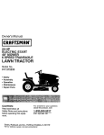
portant safety precautions.
It means
CAUTION!!!
ook for this BECOMEALERTH!
symbol
to point out
YOUR
iraSAFETY' IS INVOLVED.
...............
..............
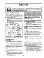
CAUTION: Always disconnect spark plug
A
spark plug in order to prevent accidental
wire
and place
whereit
contact
starting
when wire
setting
up,cannot
transporting,
adjusting or making repairs.
A WARNING
Tahe engine exhaust from this product conins cnemicats Known to the State of Canirornia to cause cancer, birth defects, or other
reproductive harm.
2
:.11
PRODUCT SPECIFICATIONS
CONGRATULATIONS
on your purchase of a Sears
Tractor. It has been designed, engineered and manufactured to give you the best possible dependability and
performance°
Should you experience any problem you cannot easily
remedy, please contact your nearest Sears Authorized
Service CentedDepartment.
We have competent, welltrained technicians and the proper tools to service or repair
this tractor°
Please read and retain this manual. The instructions wilt
enable you to assemble and maintain your tractor properly.
Always observe the "SAFETY RULES'L
MODEL
NUMBER
917°258555
SERIAL
NUMBER
DATE OF PURCHASE
THE MODELAND
SERIAL NUMBERS WILL BE FOUND
ON A PLATE UNDER THE SEAT.
YOU SHOULD RECORD BOTH SERIAL NUMBER AND
DATE OF PURCHASE AND KEEP IN A SAFE PLACE
i FOR FUTURE REFERENCE.
F
,
..................
MAINTENANCE
RESPONSIBILITIES
.
Read and observe
.
Fo!low a regular schedule in maintaining, caring for and
using your tractor°
Follow the instructions under"Customer
Responsibilities" and "Storage" sections of this owner's manual.
°
15,,0
GASOLINE CAPACITY
125 GALLONS
OIL TYPE (API-SF!SG/SH):
SAE 10W30 (above 32°F)
SAE 5W-30 (below 32°F)
OIL CAPACITY:
W/FILTER:
4,,0 PINTS
W/O FILTER: 3.,5 PINTS
SPARK PLUG:
(GAP: 040")
CHAMPION RC12YC
VALVE CLEARANCE:
NOT ADJUSTABLE
GROUND SPEED (MPH):
FORWARD: 0 - 5,7
REVERSE: 0-25
TIRE PRESSURE:
FRONT:
REAR:
CHARGING SYSTEM:
3 AMPS BATTERY
5 AMPS HEADLIGHTS
BATTERY:
AMP/HR:
MINo CCA:
CASE SIZE:
BLADE BOLT TORQUE:
AND TYPE:
30-35 FT_ LBS.
UNLEADED REGULAR
14 PSI
10 PSI
30
240
U1R
WARNING: This tractor is equipped with an internal
combustion eng!ne and should not be used on or near any
unimproved forest-covered, brush-covered or grass-covered land unless the engine's exhaust system is equipped
with a spark arrester meeting applicable loc,_.;or state laws
(if any).. If a spark arrester is used, it should be maintained
in effective working order by the operator.
{n the state of California the above is required by law
(Section 4442 of the California Public Resources Code)_
Other states may have similar laws. Federal laws apply on
federal lands° A spark arrester for the muffler is available
through your nearest Sears Authorized Service Center/
Department (See REPAIR PARTS section of this manual)°
AGREEMENT
A Sears Maintenance Agreement is available on this producL Contact your nearest Sears store for details,,
CUSTOMER
HORSEPOWER:
the safety rules,,
LIMITED TWO YEAR WARRANTY ON CRAFTSMAN
RIDING EQUIPMENT
For two (2) years from the date of purchase, if this Craftsman Riding Equipment is maintained, lubricatedand tuned up according
to the instructionsin the owner's manual, Sears will repair or replace, free of charge, any parts found to be defective in mater_ator
workmanship._
This Warranty does not cover:
•
Expendable items which become worn during normal use, such as blades, spark plugs, air cleaners, belts, etc.
•
Tire replacement or repair caused by puncturesfrom outside objects, such as nails, thorns, stumps, or glass.
°
Repairs necessary because of operatorabuse, negligence, improperstorage or accident or the failure to maintain the
equipment accordingto the instructionscontained in the owner's manual.
Riding equipment used for commercial or rental purposes,.
LIMITED 90 DAY WARRANTY
ON BATTERY
For ninety (90) days from date of purchase, if any battery included with this riding equipment proves defeclive in material or
workmanship and our testing determines the battery will not hold a charge, Sears will replace the battery at no charge..
IN-HOME WARRANTY SERVICE ON YOUR CRAFTSMAN RIDING EQUIPMENT IS AVAILABLE AT NO-CHARGE FOR 30
DAYS FROM THE DATE OF PURCHASE. PLEASE CONTACT YOUR NEAREST SERVICE CENTER, AFTER 30 DAYS FROM
THE DATE OF PURCHASE, WARRANTY SERVICE IS AVAILABLE BY TAKING YOUR CRAFTSMAN RIDING EQUIPMENT TO
YOUR NEAREST SEARS SERVICE CENTER. (IN-HOME WARRANTY SERVICE WILL STILL BE AVAILABLE AFTER 30 DAYS
FROM THE DATE OF PURCHASE BUT A STANDARD TRIP CHARGE WILL APPLY_) THIS WARRANTY APPLIES ONLY
WHILE THIS PRODUCT 1S IN THE UNITED STATES.
This Warranty gives you specific legal rights, and you may also have other rights which may vary from stale to state
SEARS, ROEBUCK
AND CO., D/817 WA, HOFFMAN
.......................................................................................................
ESTATES,
IL 60179
iiilll,i,Ni
3
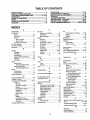
TABLE OF CONTENTS
OPERATION ........................................................... 10-15
MAINTENANCE SCHEDULE ...................................... 16
SERVICE AND ADJUSTMENTS ............................ 20-25
STORAGE ...................................................................
26
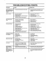
TROUBLESHOOTING ............................................ 27-28
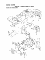
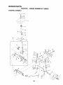
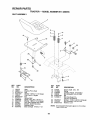
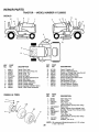
REPAIR PARTS - TRACTOR ................................. 30-47
REPAIR PARTS - ENGINE .................................... 48-53
PARTS ORDERING/SERVICE .................. BACK PAGE
SAFETY RULES ............................................................ 2
PRODUCT SPECIFICATIONS ...................................... 3
CUSTOMER RESPONSIBILITIES ..................... 3, 16-19
WARRANTY .................................................................. 3
TABLE OF CONTENTS ................................................ 4
INDEX ............................................................................
4
TRACTOR ACCESSORIES .......................................... 5
ASSEMBLY ................................................................ 7-9
iNDEX
O
A
E
Accessories .........................................................
5
Oil:
Electrical:
Cold Weather Conditions ............
I3,18
Adjustments=
Interlocks and Relays .......................
24
Brake ......................................................
22
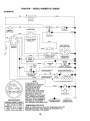
Schematic .................................................
29
Engine ......................................................
18
Carburetor. .............................................
25
Storage .................................................
26
Wiring Diagram .....................................
30
Mower:
Operation ................................................
10-15
Engine:
Front-To-Back .....................................
21
Air Filter .............................................
18
Operating Mower'. ......................................
13
Side-To-Side .....................................
21
Air Screen ............................................
19
Options:
Accessories ............................................
5
Throttle Control Cable ...................24
Cooling Fins, Engine ..........................
19
Spark Arrester .........................................
3,40
Air Filter, Engine ..............................................
18
Oil Change .................................................
18
P
Air Screen, Engine .....................................
18
Oil Level .................................................
13,18
Assembly .......................................................
7-9
Oil Type ............................................................
18
Parking Brake
11-12
B
Preparation ..............................................
13
Pads Bag
6
Repair Pads ..........................................
48-53
Pads, Replacement/Repair ...............
30-47
Battery:
Stading ..................................................
14
Charging .........................................................
7-8
Product Specifications ......................................
3
Storage ....................................................
26
Cleaning ............................................17
R
F
Connecting .......................................
7-8
Filters:
Starling with Weak Battery .......... 23
Repair Parts .......................................................
30-47
Air ..................................................................
18
Storage ....................................................
26
S
Terminals ............................................
17
Fuel ........................................................
19
Safety Rules .................................................
2
Belts:
Fuel:
Seat ..................................................................
8
Motion Drive
Type .........................................................
13
Service and Adjustments ......................
20-25
Removal/Replacement .................
22
Storage .............................................
26
Brake ..............................................................
22
Mower Blade Drive
Fuse .............................................................
24
Carburetor ...............................................
25
Removal/Replacement ................
22
G
Fuse ..............................................................
24
Blade:
Hood RemovaVlnstallation ............24
Gauge Wheels ...................................................
8
Sharpening .........................................
17
H
Motion Drive Belt
Replacement .........................................
17
Removal/Replacement ..............22
Hood RemovaVlnstafiation ........................
24
Brake Adjustment .....................................................
22
Mower Blade Drive Belt
L
C
Removal/Replacement ........... 22
Leveling Mower Deck ...............................
21
Carburetor Adjustment ..................................
25
Mower
Adjustment:
LubricationChart .....................................t6
Controls, Tractor ..........................................
11
Front-to-Back ...............................
21
M
Customer Responsibilities .................
16-19
Side-to-Side ....................................
21
Maintenance Schedule ..................................
16
Mower Installation ...................................
20
Engine:
Mower:
Air Filter ...........................................
18
Mower Removal ...................................
20
Adjustment, Front-to-Back ...........21
Air Screen, Engine ....................19
Tire Care ....................................................
8,17,23
Adjustment, Side-to-Side ............. 21
Battery ............................................
17
Slope Guide Sheet
55
Blade Sharpening ...........................17
Cooling Fins, Engine ...................
19
Spark Plugs
t9
Blade Replacement ..............................
17
Engine Oi! ....................................19
Specifications
3
Cutting Height .................................12
Fuel Filler ..........................................
19
Starling the Engine ...........................13-14
Installation ..........................................
20
Spark Plugs..........................................
19
Steering Wheel ......................................
7,23
Operation .................................................
t3
Tractor:
Stopping the Tractor.
12
Removal ........................................................
20
Blades ......................................................
17
Storage .........................................................
26
Mowing Tips ...........................................................
15
LubricationChart ...............................
16
T
Muffler ...........................................................
19
Maintenance Schedule ............ 16
Throttle Control Cable Adjustment .......24
Spark Arrester ..................................
3,40
Tire Care .............................8,t7,23
Tires .................................................8,17,23
Mulcher Plate ...................................................
9
Cutting Height, Mower ...........................12
Trouble Shooting Chart .............................
27-28
............
............................
..............................................
..........................
......
................................................
...........................
.......................
.........................................
Transaxle Repair Pads .................. 46-47
W
Warranty .................................................................
3
Wiring Diagram ........................................
30
Widng Schematic .......................................
29
4
ACCESSOFI
AND ATTACHMENTS
.............
lltt.rlt_l,ll
it
ill
i
]
ttttltl
These accessories and attachments were available through most Sears retail outlets and service centers when the tractor was purchased.
Most Sears stores can order these items for you when you provide the model number of your tractor_
ENGINE
SPARK PLUG
MAINTENANCE
GASCAN
ENGINEOIL
FUEL STABILIZER
AIR FILTER
BLADES
BELTS
%
PERFORMANCE
Sears offers a wide variety of attachments that fit yourtractor. Many of these are listed below with brief explanations of how they can help
you. This list was current at the time ofpublication;however, it may change in future years - more attachments may be added, changes
may be made in these attachments, or some may no longer be available or fit your model. Contact your nearest Sears store for the
accessories and attachments that are available for your tractor.
Most of these attachments do not require additiona!hitches or conversion kits (those that do are indicated) and are designed for easy
attaching and detaching°
SNOWBLADEforsnowremoval only, 14-inch high,48-inchwide
blade clears 42-Inch path when angled left or right. Raises, lowers
with side lever. Adjustable skids; replaceable, reversible scraper
bar° (Use with tire chains and wheat weights and/or rear drawbar
weight_)
SNOW'rHROWER has 40-inch swath Drum-type auger handles
powdery and wet/heavy snow. Mounts easily with simple pin
arrangement. Discharge chute adjusts from tractor seal 6-inch
diameter spout discharges snow t0 to 50 feet. Lift controlled at
tractor seat. (Use with chains and wheel weights and/or rear
drawbar weight°)
SPRAYERS use 12-volt DC electdc motor that connects to the
tractor batter] or other 12-volt source
Includes booms for
automatic spraying and hand held wand for spot spraying Wand
has adjustable spray pattemo For applying herbicides, insecticides, fungicides and liquid fertilizers_ ,
SPREADEPJSEEDERS make seeding, fertilizing, and weed killing easy. Broadcast spreaders are also useful for granular deicers and sand.
AERATOR promotes deep root growth for a healthy lawn. Tapered 25_inch steel spikes mounted on 10-inch diameter discs
puncture holes in soil at close intervals to let moisture soak in.
Steel weight tray for increased penetration°
BAGGER lets you collect grass clippings and leaves for a
healthier, nearer looking lawno Two Permanex containers hold
30-gallon plastic bags,
BUMPER protects front end of tractor from damage
CARTS make hauling easy° Variety of sizes available, plus
accessories such as side panel kits, tool caddy, cart cover,
protective mat and dolly..
CORING AERATOR takes small plugs out of soil to aIfow moisture and nutrients to reach grass roots. 36_inch swath. 24
hardened steeEcoring tips, 150 lb. capacity weight tray_
EASY OIL DRAIN VALVE makes oil changes easier, faster.
FRONT NOSE ROLLER canters in front of mower deck to reduce
chances of "scalping" on uneven terrain.
GANG HITCH lets you tow 2 or 3 pull-behind attachments at once,
such as sweepers, dethatchers, aerators (not for use with rollers,
carts or other heavy attachments).
GAUGE V/HEELS on both sides of the mower deck reduce
chances of "scalping" on uneven terrain. For mower decks not so
equipped°
MULCH RAKE/DETHATCHER loosens soil and flips thatch and
matted leaves to lawn surface for easy pickup, Twenty spring line
teeth° Useful to prepare bare areas forseeding. Available for front
or rear mounting.
HIGH PERFORMANCE REEL-ACTION
SPRING TINE DETHATCHER covers 36-inch wide path and
tosses thatch into large hopper° Mounts behind tractor_
MULCHING CLOSE-OUT PLATE KIT, once installed, lets you
mulch, discharge or bag clippings (bagger optional) without
changing blades° For models not equipped as 3-in-1 Convertible
mowers_ See "MOWER" in the Repair Parts section of this
manual
SWEEPERS let you collect grass clippings and leaves
TILLER has 5 hp engine and 36-inch swath to prepare seed beds,
cultivate and compost garden residue_ Tiller has its own built-in
lift and depth control system and does NOT require a sleeve hitch.
Fits any lawn, yard or garden tractor. Simply hook up to the tractor
drawbar and go? Optional
accessories
convert unit for
dethatching, aerating, hilling._without tdols,
TIRE CHAINS are heavy duty; closely spaced extra-large cross
links give smoolh ride, outstanding traction.
TRACTOR CAB has heavy duty vinyl fabric over tubular steel
frame, ABS plastic top; clear plastic windshield offers 360 degree
visibility° Hinged metal doors with catch. Keeps operator warm
and dry_ Remove vinyl sides and windshields for use as sun
protector in summer.. Optional accessories include: tinted/
tempered solid safety glasswindshield with hand operated wiper;
12-volt amber caution light for mounting on cab top.
VACS for powerfulcollectionof heavy grassclippings and leaves.
Optional wand attachment to pick up debris in hard-to-reach
places_ VAC/CHtPPER includes a chipper-shredder.
WEIGHT BRACKET for drawbar for snow removal applications°
Uses (1) 55 lb. weight.
WHEEL WEIGHTS for rear wheels provide needed traction for
snow removal or dozing heavy materials_
RAMP TOPS AND FEET let you load and unload tractor from a
pickup truck. Use with 2 x 8 or 2 x 10 lumber.,
ROLLER for smoother lawn surface. 36-inch wide, 18-inch
diameter water-tight drum holds up to 390 Ibs_ofweighL Rounded
edges prevent harm to tuff. Adjustable scraper automatically
cleans drum,
5
CONTENTS OF
i tlntit
ti
nnn
ttll
.................
i
IlJl
UitltU
Itllt
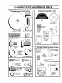
Parts Bag contents
]lll]t]tlt
tl
t
I I tl tt tltt tttttttt
shown
.........
Ilttl
full size
i,tttt
(1) Hex Bolt
3/8-16 x 1
Seat
Steering Wheel
Mulcher
Plate
(1) Large Flat Washer
(1) Lockwasher 3/8
Q
(1) Hex Bolt 5/16-18 x 1-1/4
.........
ii n iiiiiiiiiii
(1) Locknut 5/16-18
Video
Cassette
iiiiii
(1) Hex Bolt
1/2-13 x 1
L.
Manual
Parts Bag
II
(1) Shoulder Bolt
5/16-18
,llnllllllllll
ti
II
Parts bag contents
.........................
i
not shown full size
iiii ii ii i llluu
@
(I) Washer
17/32 x
1.-3116x
12 Gauge
ill
(2) Shoulder
Bolts
x(2)7/8
x i4 Gauge
Washers
3/8
©
W) Gauge
heels
(2) CenterlockNuts
Steering
Wheel
Adapter
_
1/4-20 x 3/4
2) Hex Bolts
9/32 x 5/8
x(2)16Washers
Gauge
Wheel
teering
insert
Nuts
(2)
Hex @
1/4-20
Allen Wrench
=
(2) Lock
Washers
1/4
o
Slope Sheet
6
(2) Keys
Steering
Extension
Shaft
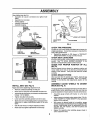
BLY
Your new tractor has been assembled at the factory with exception of those parts left unassembled for shipping purposes,
To ensure safe and proper operation of your tractor all parts and hardware you assemble must be tightened securely, Use
the correct tools as necessary to insure proper tightness.
TOOLS
REQUIRED
FOR ASSEMBLY
A socket wrench set will make assembly easien Standard
wrench sizes are listedo
(1) 3/4" Socket w!ddve rachet
(2) 7/'16" wrenches
(1) Phillips Screwdriver
(2) 1/2" wrenches
Tire pressure gauge
(1) 9/16" wrench
Utility knife
When right or left hand is mentioned in this manual, it
means when you are in the operating position (seated
behind the steering wheel),,
STEERING
BOOT
TO REMOVE TRACTOR FROM CARTON
UNPACK
•
°
•
CARTON
EXTENSION
Remove all accessible loose parts and parts cartons
from carton (See page 6).
Cut, from top to bottom, along lines on all four corners
of carton, and lay panels flat_
Check for any additional loose parts or cartons and
remove,,
BEFORE
ATTACH
ROLLING TRACTOR
STEERING
OFF SKID
°
-
SttAFT
WHEEL (See Fig. 1)
ASSEMBLE EXTENSION SHAFT AND BOOT
° Slide extension shaft onto lower steering shaft. Align
mounting holes in extension and lower shafts and
install 5/16 hex bolt and locknuto Tighten securely.
IMPORTANT: TIGHTEN BOLT AND NUT SECURELY TO
18-22 FT_ LBS TORQUE,
°
Place tabs of steering boot over tab slots in dash and
push down to secure.
INSTALL STEERING WHEEL
o Position front wheels of the tractor so they are pointing
straight forward.
°
Slide steering wheel adapter onto steering shaft extension.
°
LOWER
FIG. 1
HOW TO SET UP YOUR TRACTOR
CONNECT
I
=
.
o
Press lift lever plunger and raise attachment lift lever to
its highest position°
Release parking brake by depressing clutch/brake
pedal.
Place freewheel control in freewheeling position to
disengage transmission (See '_FOTRANSPORT" in
the Operation section of this manual).
Roll tractor backwards off skid.
Remove banding holding discharge guard up against
tractor,
7
BATTERY
I1"1
(See Figs. 2 and 3)
..........................................................
Do not short battery termi-
Positive terminal must be connected
first to prevent sparking from accidental grounding.
Remove protective materials from tractor hood and
grill.
IMPORTANT: CHECK FORAND REMOVE ANY STAPLES
IN SKID THAT MAY PUNCTU RE TIRES WHERE TRACTOR
IS TO ROLL OFF SKID,
•
I
object to contact both terminals at the
nals by allowing a wrench or any other
same time. Before connecting battery,
remove metal bracelets, wristwatch
bands, rings, etc.
•
O FF SKID (See Operation
and function of controls)
I
CAUTION:
Position steering wheel so cross bars are horizontal
(left to right) and slide inside boot and onto adapter.
Assemble large flat washer, 3/8 lock washer, 3/8 hex
bolt and tighten securely.
Snap steering wheel insert into center of steering
wheel.
TO RO LLTRACTOR
section for location
i
IIIII
°
°
•
°
•
•
I
L
ILLII
''
'
! ........
Remove cardboard packing from seat pan and lift seat
pan to raised position.
Open battery box door°
Remove terminal protective caps and discard,
If this batter,] is put into service after month and year
indicated on label (label located between terminals)
charge battery for minimum of one hour at 6-10 amps_
First connect RED battery cable to positive (+) terminal
with hex bolt, flat washer, lock washer and hex nut as
shown. Tighten securely,
Connect BLACK grounding cable to negative (-) terminal with remaining hex bolt, flat washer, lock washer
and hex nut. Tighten securely°
Close battery box door.
A
Open battery box door for:
•
Inspection for secure connections (to tighten hardware).
°
Inspection for corrosion.
°
Testing battery°
° Jumping (if required)°
°
Periodic charging..
SEAT
\
SEAT PAN
SHOULDER
BOLT
DISCARD
TERMINAL
PROTECTIVE
CAPS
__S_
''f
NUT
HEX
LOCK
WASHER
FLAT
LARGE FLAT WASHER
ADJUSTMENT
BOLT
LOCK WASHER
FIG. 4
CHECK TIRE PRESSURE
BOLT
POSITIVE
(RED) CABLE
The tires on your tractorwere overinflated at the factory for
shipping purposes. Correct tire pressure is important for'
best cutting performance.
°
Reduce tire pressure to PSi shown in "PRODUCT
SPECIFICATIONS on page 3 of this manual
NEGATIVE
(BLAC_ CABLE
FIG. 2
CHECK DECK LEVELNESS
For bestcutting resutts, mower housing should be properly
leveled° See "TO LEVEL MOWER HOUSING" in the
Service and Adjustments section of this manuat.
SEAT
PAN
CHECK
BELTS
FOR PROPER
POSITION
OF ALL
See the figures that are shown for replacing motion and
mower blade drive belts in the Service and Adjustments
section of tttis manual° Verify that the belts are routed
correctly_
BOX DOOR
CHECK BRAKE SYSTEM
After you learn how to operate your tractor, check to see
that the brake is properly adjusted. See 'q'O ADJUST
BRAKE" in the Service and Adjustments section of this
manual
FIG. 3
ASSEMBLE GAUGE
DECK (See Fig. 5)
INSTALL SEAT (See Fig. 4)
Adjust seat before tightening adjustment bolt.
°
Remove cardboard packing on seat pan.
,
Place seat on seat pan and assemble shoulder boll
o Assemble adjustment bolt, Iockwasherandflatwasher
loosely. Do not tighten.
Tighten shoulder bolt securely._
•
Lower seat into operating position and sit on seat.
•
Slide seat until a comfortable position is reached which
allows you to press clutch/brake pedal all the way
down_
o
°
WHEELS
TO
MOWER
The gauge wheels are designed to keep the mower deck in
proper position when operating mower. Be sure they are
properly adjusted to ensure optimum mower perforrnance.
°
Assemble gauge wheels with tractor on a flat level
surface.
•
•
Adjust mower to desired cutting height (See "TO ADJUST MOWER CUTTING HEIGHT" in the Operation
section of this manual)°
With mower in desired height of cut position, gauge
wheels shoutd be assembled so they are slightly off the
ground, Install gauge wheel in appropriate hole with
shoulder bolt, 318 washer, and 3/8-16 iocknut and
tighten securely_
°
Repeat for opposite side installing gauge wheel in
same adjustment hole.
Get off seat without moving its adjusted position.
Raise seat and tighten adjustment bolt securefy.
8
DEFLECTOR
SHIELD
BRACKET
LOCKNUT
SHOULDER BOLT
GAUGE WHEEL
FIG. 5
INSTALL
MULCHER
LATCH
HOOKS
PLATE
(See Figs. 6
FIG. 7
and 7)
-
TO CONVERT TO BAGGING
DISCHARGING
Install two latch hooks to mulcher plate using screw,
washer, lock washer, and weld nut as shown.
NOTE: Pre-assemble weld nut to latch hook by inserting
weld nut from the top with hook pointing down.
,
Tighten hardware securely,
•
Raise and hold deflector shield in upright position.
.
•
Place front of mulcher plate over front of mower deck
opening and slide into place, as shown..
Hook front latch into hole on front of mower deck_
°
}-took rear latch into hole on back of mower deck.
................................
_ .............
Simply remove mutcher plate and store in a safe place.
Your mower is now ready for discharging or installationof
optional grass catcher accessory.
NOTE: It is not necessary to change blades. The mulcher
blades are designed for discharging and bagging also,,
#"CHECKLIST
t
guard from mower. Raise and hold
CAUTION:
not remove
discharge
guard
whenDoattaching
mulcher
plate
and allow it to rest on plate while in
operation.
HOOK POINTS
DOWN
WELD NUT
FROM THE TOP,
LOCK
WASHER
WELD.
NUT
_-\
SCREW
LATCH
HOOK
HOOK
LOCK
I WASHER
WASHER
WELD
NUT
WASHER
MULCHER
PLATE
OR
_-'_SCREW
FIG. 6
9
BEFORE YOU OPERATE AND EIVJOY YOUR NEW
TRACTOR, WE WISH TO ASSURE THAT YOU RECEIVE
THE BESTPERFORMANCE AND SATISFACTION FROM
THIS QUALITY PRODUCT.
PLEASE REVIEW THE FOLLOWING CHECKLIST:
v" All assembly instructions have been completed.
,/ No remaining !oose parts in carton.
J Battery is properly prepared and charged, (Minimum
1 hour at 6 amps)o
,f Seat is adjusted comfortably and tightened securely,
v" All tires are properly inflated. (For shipping purposes,
the tires were overinfiated at the factory).
,/ Be sure mower deck is properly leveled side-to-side!
front-to-rear for best cutting results, (Tires must be
properly inflated for leveling),
,/ Check mower and drive belts. Be sure they are routed
properly around pulleys and inside all belt keepers.
,/" Check wiring, See that all connections are still secure
and wires are properlyclamped_
,/ Before driving tractor, be sure freewheel control is in
drive position_
WHILE LEARNING HOWTO USE YOUR TRACTOR, PAY
EXTRA A TTENTION TO THE FOLLOWING IMPORTANT
ITEMS:
,/
Engine oil is at proper level.
,/ Fue! tank is filled with fresh, clean, regular unleaded
gasoline,,
,/' Become familiar with all controls - their location and
function. Operate them before you start the engine,.
,/ Be sure brake system is in safe operating condition.
,/" It is important to purge the transmission before operating your tractor for the first time. Follow proper starting
and transmission purging instructions(See'q'o START
ENGINE and PURGE TRANSMISSION" in the Operation section of this manual).
These symbols may appear' on your tractor or in literature supplied with the product. Learn and understand their meaning.
A
BATTERY
CAUTION OR
WARNING
R EVERSE
FORWARD
FAST
SLOW
ENGINE ON
ENGINE OFF
OIL PRESSURE
CLUTCH
LIGHTS ON
LIGHTS OFF
FUEL.
CHOKE
MOWER HEIGHT
DIFFERENTIAL
LOCK
PARKING BRAKE
LOCKED
UNLOCKED
N H
REVERSE
MOWER LIFT
NEUTRAL
ATTACHMENT
CLUTCH ENGAGED
DANGER, KEEP HANDS AND FEET AWAY
HIGH
LOW
ATTACHMENT
CLUTCH DISENGAGED
PARKING BRAKE
IGNITION
HYDROSTATIC FREE WHEEL
(Hydro Models only)
.........................
i,_lll_ll_l
..................
i,r................
i
iml,,llll i
i1,,,,,,, ,i i i i,
i
i,
i
OPEBATmO
IllIHIH,
IHHmlll
Ill
ill
Ill
I I
,.....................
I,Ill"ll"ll'"ll'l I'
I
mHll
I H
II
HI
I
I
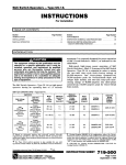
KNOW YOUR TRACTOR
READ THIS OWNER'S
MANUAL AND SAFETY RULES BEFORE OPERATING
YOUR TRACTOR
Compare the illustrations with your tractor to familiarize yourself with the locations of various controls and adjustments. Save
this manual for future reference.
ATTACHMENT
CLUTCH LEVER
IGNITION
SWITCH
LIGHT SWITCH
POSITION
AMMETER
THROTTLE!CHOKE
CONTROL
©
ATTACHMENT
LIFT LEVER
CLUTCH/BRAKE
PEDAL
PARKING
BRAKE
HEIGHT
ADJUSTMENT
KNOB
MOTION
CONTROL
LEVER
FREEWHEEL
CONTROL
APPROX.
SPEED
3 MPH
2MPH
1MPH
FIG. 8
Our tractors conform to the safety standards of the American National Standards lnstitute_
ATTACHMENT CLUTCH LEVER: Used to engage the
mower blades, or other attachments mounted to your
tractor.
MOTION CONTROL LEVER:
direction of tractor°
ATTACHMENT LIFT LEVER: Used to raise and tower the
mower deck or other attachments mounted to your tractor,
LIFT LEVER PLUNGER: Used to release attachment lift
lever when changing its position°
LIGHT SWITCH: Turns the headlights on and off_
THROTTLE/CHOKE CONTROL:
controlling engine speed,,
Selects the speed and
Used for starting and
CLUTCH/BRAKE PEDAL: Used fordeclutchtng and braking the tractor and starting the engine,,
IGNITION SWITCH:
engine.
PARKING BRAKE: Locks clutch/brake pedal into the
brake position.
HEIGHTADJUSTMENT
cutting height.
FREEWHEEL CONTROL - Disengages transmission for
pushing or slowly towing the tractor with the engine off.,
AMMETER: Indicates battery charging (+) or discharging
(-).
1
k,
Used for starting and stopping the
KNOB: Used to adjust the mower
OPERATION
k
...............................
......
I
_
.......
iiiii
.........
::
.....
/llll,
,
......................
::...
i I ,
i
II
I'
!,,!!U!!,j
III
TO SET PARKING
BRAKE (See Fig. 9)
Your tractoris equipped with an operator presence sensing
switch. When engine is running, any attempt by the
operator to leave the seat without first setting the parking
brake will shut off the engine°
o
Depress clutch/brake pedal intofull"BRAKE" position
and hold,
°
Place parking brake lever in"ENGAGED" position and
releasepressurefrom clutch/brakepedat, Pedal should
remain in "BRAKE" position. Make sure parking brake
will hold tractor secure.
• .:....:
-BRAKE,'__
" _'_
_:_J
/
/
•
•
.,AR,
.AKE
NG
ENGAGED
.o=.,o.
'11
,,,11,11
•
Move attachment clutch lever'to "DISENGAGED" position.
Depress clutch/brake pedal intofulI"BRAKE" position.
°
Move motion contro! lever to neutral iN) position.
IMPORTANT: THE MOTION CONTROL LEVER DOES
NOT RETURN TO NEUTRAL iN) POSITION WHEN THE
CLUTCHIBRAKE PEDAL IS DEPRESSED.
ENGINE Move throttle control to slow position_
NOTE: Failure to move throttle control to slow position and
allowing engine to idle before stopping may cause engine
to "backfire".
°
Never' use choke to stop engine_
! .................
CONTROL
j III
(See Fig. 9)
Operating engine at less than full throttle reduces the
battery charging rate.
Full throttle offers the best bagging and mower performance.
(See
Start tractor with motion control lever in neutral iN)
position_
Release parking brake and clutch/brake pedal.
HEIGHT (See
Turn knob counterclockwise (v-'_)to
height°
lower cutting
The cuttingheight range is approximately 1-1t2"to 4". The
heights are measured from the ground to the blade tip with
the engine not running. These heights are approximate
and may vary depending upon soil conditions, height of
grass and types of grass being mowed.
GROUND DRIVE -
Turn ignition key to "OFF" position and remove key.
Always remove key when leaving tractor to prevent
unauthorized use.
......
The cutting height is controlled by turning the height
adjustment knob in desired direction.
•
Turn knob clockwise ((_) to raise cutting height.
(See Fig. 9)
•
i,!11
TO ADJUST MOWER CUTTING
Fig. 9)
KNOB
MOWER BLADES -
°
iii
° Slowly move motion control lever' to desired position.
NOTE: The effort to move the motion control lever will
reduce after the first few hours of use. This is normal.
FIG. 9
°
i,
The direction and speed of movement is controttedby the
motion control lever.
°
"DISENGAGED"
-
i,,
TO MOVE FORWARD AND BACKWARD
Fig. 9)
-
HEIGHT ADJUSTMENT
.........
Always operate engine at full throttle.
'. _."..',' _.//" MOTION CONTROL
, '; .... _
_
LEVER \
CLUTC_RAKE
PEDAL
"DRIVE" POSITION
,i,i
TO USE THROTTLE
, SWITCH
/DISENGAGED"
-_--_
iii
pletely, as described above, before leaving the operator s position; to empty
CAUTION:
Always
grass catcher,
etc. stop tractor com-
I_
ATTACHMENT CLUTCH LEVER
"ENGAGED" POSITION
IGNITION
c "o%%L
Jl'll'l
NOTE: Under certain conditions when tractor is standing
idlewith the engine running, hot engine exhaust gases may
cause "browning" of grass. To eliminate this possibility,
always stop engine when stopping tractor on grass areas.
HOW TO USE YOUR TRACTOR
STOPPING
...................................................
result in severe eye damage. Always wear safety'glasses or eye shields while operating your
tractor or performing any adjustments or repairs, We recommend a wide vision safety mask
The
of anyor
tractor
can safety
result glasses.
in foreign objects thrown into the eyes, which can
over operation
the spectacles
standard
I_
THROTTLE/
/
i2
°
The average lawn should be cut to approximately 2-1/2
inches during the cool season and to over3 inches
during hot months. For healthier and better looking
lawns, mow often and after moderate growth.
=
For best cutting performance, grass over 6 inches in
height should be mowed twice. Make the first cut
relatively high; the second to desired height,
,,,i,,,j_,,i,_Jl,,,,ii
,i,i1,11, i
i, i1,1, i, k
I
.......
I'1'1'1'1'11'1'111
III
OPERATIC
TO OPERATE
MOWER (See Fig. 10)
TO TRANSPORT
(See Figs. 8 and 11)
Your tractoris equipped with an operator presence sensing
switch. Any attempt by the operator to leave the seat with
the engine running and the attachment clutch engaged will
shut off the engine.
•
Select desired height of cuL
•
Lower mower with attachment lift control
,, Start mower blades by engaging attachment clutch
control°
° TO STOP MOWER BLADES - disengage attachment
clutch control.
When pushing or towingyour tractor,be sure to disengage
transmission by placing freewheel controlin freewheeling
position. Free wheel control is located at the rear drawbar
of tractor.
o Raise attachment lift to highest position with attachment lift control
•
Pull freewheel control knob out and hold in position by
inserting retainer spring into forward hole of control
rod°
°
Do not push or tow tractor at more than two (2) MPH_
•
To reengagetransmission, reverse above procedure.
NOTE: To protect hood from damage when transporting
without either the entire grass catcher,
I
your tractor on a truck or a trailer, be sure hood is closed
on
mowers Donot
so equipped,
dis- .............
I
and secured to tractor. Use an appropriate means of tying
CAUTION:
operate or
thethe
mower
Charge guard in p!ace"
hood to tractor (rope, cord, etc).
I!
!_
FIG. 11
BEFORE STARTING THE ENGINE
CHECK ENGINE OIL LEVEL (See Fig. 17)
•
°
=
°
FIG. 10
TO OPERATE
ON HILLS
°
.......................................
I
,_
I _
i u
,
°
•
•
•
u
CAUTION: Do not drive up or down hills
with slopes greater than 15 ° and do not
drive
acr°ss any slope.
I
I
I
Choose the slowest speed before starting up or down
hills.
Avoid stopping or changing speed on hills°
If slowing is necessary, move throttle control lever to
slower position°
If stopping is absolutely necessary, push clutch!brake
pedal quickly to brake position and engage parking
brake°
Move motion control lever to neutral (N) position°
IMPORTANT:
THE
MOTION
CONTROL
LEVER
DOES
NOT RETURN TO NEUTRAL (N) POSITION WHEN THE
CLUTCHIBRAKE PEDAL IS DEPRESSED,
•
To restart movement, slowly release parking brake and
clutch/brake pedal
°
Slowly move motion control lever to slowest setting.
o Make all turns slowly.
13
The engine inyour tractor has been shipped, from the
factory, already filled with summer weight oil.,
Check engine oil with tractor on level ground°
Unthread and remove oil fill cap/dipstick; wipe off off.
Reinsert the dipstickintothe tube and rest oilfill cap on
the tube. Do not thread the cap ontothe tube. Remove
and read oil level If necessary, add oil until "FULL"
mark on dipstick is reached. Do not overfill.
For cold weather operation you should change oil for
easier starting (See "OIL VISCOSITY CHART" in the
Customer Responsibilitiessection of this manual),
To change engine oil, see the Customer Responsibilities section in this manual°
ADD GASOLINE
COLD WEATHER STARTING ( 50° F and below)
=
°
Fitl fuel tank_ Use fresh, clean, regular unleaded
gasolinewith a minimum of 87 octane, (Use of leaded
gasoline will increase carbon and lead oxide deposits
and reduce vatve life). Do not mix oil with gasoline.
Purchase fuel in quantities that can be used within 30
days to assure fuel freshness
IMPORTANT: WHEN OPERATING iN TEMPERATURES
BELOW 32°F(00C), USE FRESH, CLEAN WINTER GRADE
GASOLINE TO HELP INSURE GOOD COLD WEATHER
START1NG_
WARNING: Expedence indicates that alcohol blended
fuels (called gasohol or using ethanol or methanol) can
attract moisture which leads to separation and formation of
acids during storage. Acidic gas can damage the fuel
system of an engine while in storage_ To avoid engine
probterns,the fuel system should be emptied before storage of 30 days or longer. Drain the gas tank, start the
engine and let it run until the fuel lines and carburetor are
empty. Use fresh fuel next season. See Storage Instructions for additional information.
Never use engine or
carburetor cleaner products in the fuel tank or permanent
damage may occur°
When engine starts, allowengine to runwiththe throttle
control in the choke position until the engine runs
roughly,then move throttle controlto fast position, This
may require an engine warm-up period from several
seconds to several minutes, depending on the temperature.
HYDROSTATIC TRANSMISSION WARM UP
o
,
Before ddving the unit in cold weather, the transmission should be warmed up as follows:
° Be sure the tractor is on level ground.
• Place the motion control lever in neutral.
Release the parking brake and let the clutch/brake
slowfy return to operating position.
• Allow one minute for'transmission to warm up, This
can be done during the engine warm up period°
The attachments can also be used during the engine
warm-up period after the transmission has been warmed
upo
NOTE; If at a high altitude (above 3000 feet) or in cold
temperatures (below 32 F) the carburetor fuel mixture may
need to be adjusted for best engine performance. See "TO
ADJUST CARBURETOR" in the Service and Adjustments
section of this manual.
filler neck. Do notoverfiiL Wipeoffany
spilled
oil orFill
fuel.
not store,
spill
or
CAUTION:
to Do
bottom
of gas
tank
use gasoline near an open flame.
PURGE TRANSMISSION
TO START ENGINE (See Fig. 9)
When starting the engine for the first time or if the engine
has run out of fuel, it will take extra cranking time to move
fuel from the tank to the engtne_
•
Be sure freewheel control is in the transmission engaged position.
°
°
Sit on seat in operating position, depress clutchforake
pedal and set parking brake.
Place motion control lever in neutral (N) position.
°
Move attachment clutch to "DISENGAGED" position.
=
Move throttle control to choke position.
To ensure proper operation and performance, it is recommended that the transmission be purged before operating
tractor for the first time_ This procedure will remove any
trapped air inside the transmission which may have developed dunng shipping of your tractor'.
IMPORTANT; SHOULD YOUR TRANSMISSION REQUIRE
REMOVAL FOR SERVICE OR REPLACEMENT,
IT
SHOULD BE PURGED AFTER REINSTALLATION
BEFORE OPERATING THE TRACTOR.
Note: Before starting, read the warm and cold starting
procedures below..
-
Place tractor' safely on level surface with engine off and
parking brake set.
°
°
Disengage transmission by placing freewheel control
in freewheeling position (See "TO TRANSPORT" in
this section of manual)°
•
Sitting in the tractor seat, start engine. After the engine
is running, move throttle control to slow position.. With
motion control lever' in neutral (N) position, slowly
disengage clutchforake pedal,
o
Move motion control lever to full forward position and
hold for five (5) seconds. Move lever to full reverse
position and hold for five (5) seconds. Repeat this
procedure three (3) times.
Insert keyinto ignition and turn key clockwise to"START"
position and release key as soon as engine starts. Do
not run starter continuously for more than fifteen seconds per minute° If the engine does not start after
several attempts, move throttle control to fast position,
wait a few minutes and try again, tf engine still does not
start, move the throttle control back to the choke
position and retry_
WARM WEATHER STARTING (50° F and above)
•
When engine starts, move the throttle control tothe fast
position.
° The attachments and ground drive can now be use& tf
the engine does not accept the load, restart the engine
and allow it to wam] up for one minute using the choke
as described above.
14
OPERATI
NOTE: During this procedure there will be no movement of
ddve wheels. The air isbeing removed from hydraulicdrive
system°
o Move motioncontrolleverto neutral (N) position_Shutoff engine and set parking brake.
o
•
.
•
Engage transmission by placing freewheel control in
driving position (See '%0 TRANSPORT" in this section
of manual).
Sitting in the tractor seat, start engine. After the engine
is running, move throttle control to half (1/2) speed°
With motion control lever in neutral (N) position, slowly
disengage clutch/brake pedal..
Slowly move motion control lever forward, after the
tractor moves approximately five (5) feet, slowly move
motion control lever to reverse position. After the
tractor moves approximately five (5) feet return the
motion controt lever to the neutral (N) position. Repeat
this procedure with the motion control lever three (3)
times.
°
Do not mow grass when it is wet.. Wet grass will plug
mower and leave undesirable clumps. Allow grass to
dry before mowing,.
°
Always operate engine at ful_throttle when mowing to
assure better mow=ng performance and proper discharge of material Regulate ground speed by selecting a low enough gear to give the mower cutting
performance as well as the quality of cut desired..
=
When operating attachments, select a ground speed
that will suit the terrain and give best performance of
the attachment being used.
MULCHING
IMPORTANT:
FOR BEST PERFORMANCE, KEEP
MOWER HOUSING FREE OF BUILT*UP GRASS AND
TRASH. CLEAN AFTER EACH USEr
°
The special mulching blade will recut the grass clippings many times and reduce them in size so that as
they fall onto the lawn they will disperse into the grass
and not be noticed_ Also, the mulched grass will
biodegrade quickly to provide nutrients for the lawn.
Always mulch with your highest engine (blade) speed
as this will provide the best recutting action of the
blades.
°
Avoid cutting your lawn when it iswet. Wet grass tends
to form clumps and interferes with the mulching action.
The best time to mow your lawn is the early afternoon°
At this time the grass has dried and the newly cut area
wilt not be exposed to the direct sun°
For best results, adjust the mower cutting height so that
the mower cuts off only the top one-third of the grass
blades (See Fig. I3). For extremely heavy mulching,
reduce your width of cut on each pass and mow slowly°
Your tractor is now purged and now ready for normal
operation_
MOWING TIPS
°
o
°
•
°
°
MOWING TIPS
Tirechains cannot be used when the mower housing is
attached to tractor°
Mower should be properly leveled for best mow!ng
performance. See q'O LEVEL MOWER HOUSING in
the Service and Adjustments section of this manual,
The left hand side of mower should be used for trimming.
Drive so that clippings are discharged onto the area
that has been cut.. Have the cut area to the right of the
tractor° This will result in a more even distribution of
clippings and more uniform cutting.
°
°
When mowing large areas, start by turning to the right
so that clippings will discharge away from shrubs,
fences, ddveways, etco After one or two rounds, mow
in the opposite direction making left hand turns until
finished (See Fig. 12)o
=
If grass is extremely tall, it should be mowed twice to
reduce load and possible fire hazard from dried clippings. Make first cut relatively high; the second to the
desired height.
Certain types of grass and grass conditions may require that an area be mulched a second time to completely hide the clippings° When doing a second cut,
mow across or perpendicular to the first cut path.
Change your cutting pattern from week to week. Mow
north to south one week then change to east to west the
next week. This will help prevent matting and graining
of the lawno
FIG. 13
FIG. 12
15
CU
RESPONSIBI
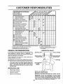
MA,.TE.ANCE
SCHEOU'E
AS YOU COMPLETE
REGULAR SERVICE
o'_.
Check Brake Operation
iT
_._
._
/__._ERVICE
: I/
Check Tire Pressure
V'
Check for Loose Fasteners
_
:_
........
R,
R.-"
I
._
._O_
DATES
..........
_'
_##7
_##
_R
iA
!c
iT
0
R
Clean Battery and Terminals
_
_#'
Check Transaxte Cooling
Adjust Blade Be!!(s) Tenslon
......
t_'s .........................
Adjust Motion Drive Belt(s] Tension
_5
Check Engine Oil Level
'ii'.Change Engine Oil
....
Clean Ai!,,,Filter
E
clean
G
Inspect MuffiedSpark
_
_#'
]
_'_,.a
I_
_'2
Air Screen
= _##
.......
_2
Arrester
.
......
_2
I
.
.
i
t.......
_#'
.....
Replace Air Filter Paper Cartridge
_2
Repiace Fuel Filter
if
I _ Change more often when opereting under a heavy load or In high ambient tempemlures
2 * Service more often when operating in dirty or dus_ conditions.,
3 - if equipped with oil filter, change oil every 50 hours.
4 -RepIace blades more often when mowing in sandy soil,
GENERAL
:
'.'.'.'...
_#'
I R'ep aceO,
F,te, (.oqu ppo )
NF Cle.an E.ngin, Cooilng Fins
Replace Spark Plug
i
RECOMMENDATIONS
5 - if equipped with adjustable system.
6. Not required If equtpped with maintenance-free batte_
7 _ Tighten front axle pivot bolt to 35 ft.-Ibs maximum
De not m,ertlghieno
LUBRICATION
CHART
®
The warranty on this tractor does not cover items that have
been subjected to operator abuse or negligence. To
receive full value from the warranty, operator must maintain
tractor as instructed in this manual
®
Some adjustments will need to be made periodically to
properly maintain your tractor.,
_INDLE ZERK ®
BEARING
ZERK
FRONT WHEEL (_
BEARING ZERK
All adjustments in the Service and Adjustments section of
this manual should be checked at least once each season.
,®
Once a year you should replace the spark plug, clean
or replace air filter, and check blades and belts for
wear. A new spark plug and clean air filter assure
proper air-fuel mixture and help your engine run better
andlast longer.
BEFORE
EACH
Check engine oil level
=
Check
°
Check tire
°
Check
operation,.
(_) SAE 30 OR 10W30 MOTOR OIL
pressure.
for loose
CLUTCH
PIVOT(S)
USE
o
brake
@
fasteners°
®
GENERAL PURPOSE GREASE
®
REFER TO CUSTOMER RESPONSIBILITIES
"ENGINE"
SECTION
IMPORTANT:
DO NOT OiL OR GREASE THE PIVOT POINTS
WHICH HAVE SPECIAL NYLON BEARINGS,
VISCOUS LUBRICANTS WILL ATTRACT DUST AND DiRT THAT WILL SHORTEN
THE LIFE OF THE SELF-LUBRICATING
BEARINGS.
IF YOU
FEEL THEY MUST BE LUBRICATED,
USE ONLY A DRY, POWDERED GRAPHITE TYPE LUBRICANT SPARINGLY,
16
,i ,1111_,,1111,,,i,1,111
III
ii1,1
i,i
I
iii
ii
CUSTOMER
_[iiiijllllll
:
..............
,i,_'ll'U"'111'1
,Ir
RESPONSIBILITI
Jl' i1_
i1,1,11,
i,i
•
TRACTOR
Always observe safety rules when performingany maintenanceo
BRAKE OPERATION
If tractor requires more than six (6) feet stopping distance
at high speed in highest gear, then brake must be adjusted°
(See "TO ADJUST BRAKE" in the Service and Adjustments section of this manual)°
TIRES
.
Maintain proper air pressure in all tires (See "PRODUCT SPECIFICATIONS" on page 3 of this manual),.
= Keep tires free of gasoline, oil, or insect control chemicals which can harm rubber°
•
Avoid stumps, stones, deep ruts, sharp objects and
other hazards that may cause tire damage_
NOTE: To seal tire punctures and prevent fiat tires due to
slow leaks, tire sealant may be purchased from your local
parts dealer,. Tire sealant also prevents tire dry rot and
corrosion.
The blade can be sharpened with a file or on a grinding
wheel. Do not attempt to sharpen while on the mower..
•
To check blade balance, you will need a 5/8" diameter
steel bolt, pin, or a cone balancer., (When using a cone
balancer, follow the instructions supplied with balancer)o
•
Slide blade on to an unthreaded portion of the steel bolt
or pin and hold the bolt or pin parallel with the ground.
If blade is balanced, it should remain in a horizontal
position° If either end of the blade moves downward,
sharpen the heavy end until the blade is balanced.
NOTE: Do not use a nail for balancing blade. The lobes of
the center hole may appear to be centered, but are not.
CENTER HOLE
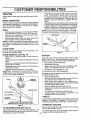
BLADE CARE
For best results mower blades must be kept sharp° Replace bent or damaged blades.
BLADE REMOVAL
(See Fig. 14)
°
Raise mower to highest position to allow access to
blades.
= Remove hex bolt, Iockwasher and flat washer securing
blade.
= Install new or resharpened blade with trailing edge up
towards deck as shown_
o Reassemble hex bolt, lock washer and flat washer in
exact order as shown.
o Tighten bolt securely (30-35 Ft. Lbs. torque).
IMPORTANT: BLADE BOLT IS GRADE 8 HEATTREATED.
NOTE; We do not recommend sharpening blade- but ifyou
do, be sure the blade is balanced.
BLADE
MANDREL
TRAILING EDGE
L
FLAT WASHER
LOCK
HEX BOLT
*A GRADE 8 HEAT TREATED BOLT CAN BE
IDENTIFIED BY SIX LINES ON THE BOLT HEAD,
FIG. 14
TO SHARPEN
,i i,,,,,,i,i ..............
I '_' i,,,11
BLADE (See Fig. 15)
/
/
FIG. 15
BATTERY
Your tractor has a battery charging system which is sufficient for normal use. However, periodic charging of the
battery with an automotive charger will extend its life_
•
Keep battery and terminals clean.
•
Keep battery bolts tight°
°
Keep small vent holes open (See "CONNECT BATTERY" in the Assembly section of this manual)°
° Recharge at 6-10 amperes for 1 hour,.
TO CLEAN BATTERY AND TERMINALS
Corrosion and dirt on the battery and terminals can cause
the battery to "leak" power,,
•
Open battery box door.
•
Disconnect BLACK battery cable first then RED battery cable and remove battery from tractor°
° Wash battery with solution of four tablespoons of
baking sodato one gallon of watei'. Be careful notto get
the soda solution into the cells°
°
Rinse the battery with plain water and dry.
°
Clean terminals and battery cable ends with wire brush
until bright.
°
Coat terminals with grease or petroleum jelly.
•
Reinstall battery (See "CONNECT BATTERY" in the
Assembly section of this manual),.
V-BELTS
Check V-belts for deterioration and wear after 100 hours of
operation and replace if necessary. The belts are not
adjustable,. Replace belts if they begin to slip from wear.
TRANSAXLE
COOLING
The fan and cooling fins of transmission should be kept
clean to assure proper cooling.
Care should be taken to keep the blade balanced,. An
Do not attempt to clean fan or transmission while engine is
unbalanced blade willcause excessivevibration and evenrunning or while the transmission is hoL
tual damage to mower and engine.
17
iiil,_,,_,,,,,,,,,_
,,_, ,,
CU
BILiTIE
,,ittl,t,tttll,t
tt t,tll,, t
Q
O
Inspect cooling fan to be sure fan blades are intact and
clean.
COVER KNOB
AIR CLEANER
COVER
Inspect cooling fins for dirt, grass clippings and other
materials. To prevent damage to seals, do not use
compressed air' or' high pressure sprayer to clean
cooling fins.
TRANSAXLE
WING NUT
FOAM
PRE-CLEANER
PUMP FLUID
The transaxle was sealed at the factory and fluid maintenance is not required for the life of the transaxleo Should the
transaxle ever leak or require servicing, contact your nearest authorized service center/departmento
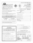
ENGINE
LUBRICATION
PAPER CARTRIDGE
Only use high quality detergent oil rated with AP1 service
classification SF, SG, or SH. Select the oirs SAE viscosity
grade according to your expected operating temperature.
OIL FILL
CAP/DIPSTICK
AIR
SCREEN
s_,_=
vlscosrn, GRAdF-S
1
°F
°C
_2D_
*30 _
09
-20 °
TEMPERATURE
30 =
32"
40 '_
-10 _'
60*
1'0=
80 _
204
AIR CLEANER
BASE
100 °
30"
40"
RANGE ANT{CIPATED BEFORE NEXT OIL CHANGE
FIG. 16
Change the oil after every 50 hours of operation orat least
once a year if the tractor is not used for 50 hours in one year.
OIL DRAIN
PLUG
Check the crankcase oil level before starting the engine
and after each eight (8) hours of operation° Tighten oil fill
cap/dipstick securely each time you check the oil level..
FIG. 17
AIR FILTER (See Fig. 17)
TO CHANGE ENGINE OIL (See Fig° 17)
Determine temperature range expected before oil change.
All oil must meet API service classification SF, SG, or SH.
,
Be sure tractor is on leve! surface_
Your engine will not run properly using a dirty air filter°
Clean the foam pre-cleaner after'every 25 hours of operation or every season. Service paper' cartridge every 100
hours of operation or every season, whichever occursfirst°
•
o
Oil will drain more freely when warm.
Catch oil in a suitable container°
Service air cleaner more often under dusty conditions.
°
Remove knob and cover.
-
Remove oil fill cap/dipstick. Be careful not to allow dirt
to enter the engine when changing oil
°
Remove wing nut and air cleaner from base°
TO SERVICE PRE-CLEANER
°
o
Remove drain plug.
After oil has drained completely, replace oil drain plug
and tighten securely.
=
°
Slide foam pre-cleaner off cartridge.
Wash it in liquid detergent and water.
=
Refill engine with oil througtl oil fill dipstick tube. Pour
slowly. Do not overfill. For approximate capacity see
"PRODUCT SPECIFICATIONS" on page 3 of this
manual°
•
Squeeze it dry in a clear} cloth. Allow it to dry,
=
Use gauge on oil fill cap/dipstick for checking level.
Insert dipstick into the tube and rest the oil fill cap or} the
tube. Do not thread the cap onto the tube when taking
reading. Keep oil at "FULL" line on dipstick. Tighten
cap onto the tube securely when finished.
°
Saturate it in engine oil Wrap it in clean, absorbent
cloth and squeeze to remove excess oil.
TO SERVICE CARTRIDGE
•
Replace a dirty, bent, or damaged cartridge.
NOTE: Do not'washthe paper cartridge or use pressurized
air',as this will damage the cartridge.
18
-
Reinstalf the pre-cleaner (cleaned and oiled) over the
paper cartddge.
°
Reassemble air cleaner, wing nut, cover'and tighten
knob securely.
i1_111_11,1,
i,
i
L II III'IM'I',,',
I
II Ill
CUSTOME
...................................................
BILITIES
•
CLEAN AIR SCREEN
.........................................
ii
(See Fig. 17)
i ill
,,,,, ,., .....................
i,iil,l,i
, ii,
MUFFLER
Air screen must be kept free of dirt and chaff to prevent
engine damage from overheating. Clean with a wire brush
or compressed air to remove dirt and stubborn dried gum
fibers.
Inspect and replace corroded muffler and spark arrester (if
equipped) as it could create a fire hazard and/or damage,
CLEAN
Replace spark plugs at the beginning of each mowing
season or after every 100 hours of operation, whichever
occurs first. Spark plug type and gap setting are shown in
"PRODUCT SPECIFICATIONS" on page 3 of this manual..
AIR INTAKE/COOLING
SPARK
AREAS
To insure proper cooling, make sure the grass screen,
cooling fins, and other external surfaces of the engine are
kept clean at all times.
PLUGS
IN-LINE FUEL FILTER
(See Fig. 19)
Every I00 hours of operation (more often under extremely
dusty, dirty conditions), remove the blower housing and
other cooling shrouds. Clean the cooling fins and external
surfaces as necessary° Make sure the cooling shrouds are
reinstalled,.
The fuet filter should be replaced once each season. If fuel
• ter becomes clogged, obstructingfuel flow to carburetor,
replacement is required°
•
NOTE: Operating the engine with a blocked grass screen,
dirt,.#or plugged cooling fins, and/or cooling shrouds removed will cause engine damage due to overheating.
With engine cool, remove filter and plug fuel line
sections.
•
Place new fuel filter in position in fuel line with arrow
pointing towards carburetor..
•
Be sure there are no fuel line leaks and clamps are
properly positioned_
°
Immediately wipe up any spilled gasoline°
ENGINE OIL FILTER
(See Fig. 18)
Replace the engine oil filter every' season or every other oil
change if the tractor is used more than 100 hours in one
year°
_, Drain oil from engine crankcase (See "TO CHANGE
ENGINE OIL" in this section of this manual, through
step remove drain plug).
,
Remove oil filter and wipe off filter adapter.
°
Apply a thin coating of new engine oil to the rubber
gasket on replacement oil filter..
.
Install replacement oil filter on filter adapter. Turn oil
filter clockwise until rubber gasket contacts the filter
adapter, then tighten filter an additional 1/2 turn°
.
,
CLAMP
MP
FIG. '19
Fill crankcase with new oil (See "TO CHANGE ENGINE OIL" in this section of this manual). For approximate capacity see "PRODUCT SPECl FICATIONS" on
page 3 of this manual
CLEANING
Start the engine and check for oil leaks. Correct any
leaks before placing engine into full operation.
°
Clean engine, battery', seat, finish, etc. of all foreign
matter.
•
Keep finished surfaces and wheels free of all gasoline,
oil, etc.
•
Protect painted surfaces with automotive type wax,.
We do not recommend using a garden hose to clean your
tractor unless the electrical system, muffler, air filter and
carburetor are covered to keep water ouL Water in engine
can result in a shortened engine tifeo
FIG. 18
19
.......................
illlllllllllll illi i, :l i,
L,,/IJ/,,IIIIIIIII
......................
AND ADJUSTMENTS
iiu iiiiii
...........
CAUTION:
°
°°
°
°
o
II
i
II I..................
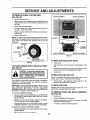
BEFORE PERFORMING ANY SERVICE OR ADJUSTMENTS:
Place motion control lever in neutral (N) position.
Depress
clutch/brake
pedal
fully and set parking
brake.
Place attachment
clutch
in "DISENGAGED"
position.
Turn ignition key "OFF" and remove key,
Make sure the blades and all moving parts have completely stopped.
Disconnect spark plug wire from spark plug and place wire where it cannot come in contact
with plug.
I
illlljilll
Ill
illl
Ill
II
Illllll
Illl
II
..........................
TRACTOR
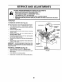
TO REMOVE
MOWER (See Fig. 20)
LEVER
Mower willbe easier to remove from the right side of tractor..
•
•
,
Place attachment clutch in "DISENGAGED" position_
Move attachment lift lever forward to lower mower toits
towest position_
Roll belt off engine pulley.
°
Disconnect clutch rod from clutch lever by removing
retainer spring.
•
Disconnect anti-sway bar from chassis bracket by
removing retainer spring.
°
Disconnect suspension arms from rear deck brackets
by removing retai!ler springs°
Disconnect front linksfrom deck by removing retainer
springs.
Raise liftlever to raise suspension arms. Slide mower
out from under tractor.
°
°
IMPORTANT:
IF AN ATTACHMENT OTHER THAN THE
MOWER 1S TO BE MOUNTED TO THE TRACTOR, THE
R.H. AND L.H. SUSPENSION ARMS MUST BE REMOVED
FROM TRACTOR,
RETAINER
SPRING
ANTI-SWAY BAR
TO INSTALL MOWER (See Fig. 20)
°
Raise attachment lift lever to its highest position.
°
Slide mower under tractor with discharge guard to right
side of tractor°
°
o
Lower lift lever to its lowest position,.
Install mower in reverse order of removal instructions,
RETAINER
SPRINGS
(BOTH SIDES)
FIG. 20
2O
i JillUII'II'
U
I I[LII
TO LEVEL MOWER
HOUSING
FRONT-TO-BACK ADJUSTMENT (See Figs° 23 and 24)
IMPORTANT: DECK MUST BE LEVEL SIDE-TO-SIDE, tF
THE FOLLOWING FRONT-TO-BACK ADJUSTMENT tS
NECESSARY, BE SURE TO ADJUST BOTH FRONT LINKS
EQUALLY SO MOWER WILL STAY LEVEL StDE-TOSIDE_
To obtain the best cutting results, the mower housing
should be adjusted so that the front is approximately 1/8" to
1/2" lower than the rear when the mower is in its highest
position.
Check adjustment on right side of tractor.. Measure distance"D" directly in front and behind the mandrel at bottom
edge of mower housing as shown.
o Before making any necessary adjustments, check that
both front linksare equal in length° Both links should be
approximately 10-3/8'L
tf links are not equal in length, adjust one link to same
length as other link.
= To lower front of mower loosen nut "E" on both front
links an equal number of turns.
•
When distance "D" is 1/8" to 1/2" lower at front than
rear, tighten nuts "F" against trunnion on both front
links°
•
To raise front of mower, loosen nut"F" from trunnion on
both front links., Tighten nut "E" on both front links an
equal number of turns,,
•
When distance "D" is 1/8" to 1/2" lower at front than
rear, tighten nut"F" against trunnion on both front links.
°
Recheck side4o-side adjustment°
Adjust the mower while tractor is parked on level ground or
driveway.
Make sure tires are properly inflated (See
,I
PRODUCT SPECIFICATIONS 'J on page 3 of this manual).
if tires are over or underinflated, you will not properly adjust
your mower°
SIDE-TO-SIDE ADJUSTMENT (See Figs. 21 and 22)
.
Raise mower to its highest position.
=
At the midpoint of both sides of mower, measure height
from bottom edge of mower to ground_ Distance"A"on
both sides of mower should be the same or within 1/4"
of each other°
-
If adjustment is necessary, make adjustment on one
side of mower only,.
To raise one side of mower, tighten lift link adjustment
nut on that sider
To lower one side of mower, loosen lift link adjustment
nut on that side.
•
•
NOTE: Each full turn of adjustment nut will change mower
height about 1/8"o
•
Recheck measurements after adjusting.
BOTTOM EDGE
OF MOWER TO
GROUND
BOTTOM EDGE
OF MOWER TO
GROUND
GROUND LINE
A
FIG. 21
%\o_
_
MANDREL
FIG, 23
BOTH FRONT LINKS MUST BE EQUAL IN LENGTH
LIFT LINK
ADJUSTMENT
NUT
FIG. 22
NUT "E"
NUT
FRONT LINKS
21
TRUNNION
FIG. 24
.................
ii ii HI'N",
SERVICE AND ADJUSTMENTS
....................
TO REPLACE
MOWER
i
BLADE
DRIVE
BELT
WITH PARKING BRAKE "ENGAGED"
NUT "A"
(See Fig. 25)
The mower blade drive belt may be replaced without tools..
Park the tractor on level surface_ Engage parking brake.
BELT REMOVAL= Remove mower from tractor (See "TO REMOVE
MOWER" in this section of this manual).
•
Work belt off both mandrel pulleys and idler pulleys°
•
Pull belt away from mower°
BELT iNSTALLATION °
install new bett in reverse order of removal
Make sure belt is in all pulley grooves and inside all belt
guides.
Install mower in reverse order' of removal instructions.
MANDREL
PULLEY
ARM
IDLER
PULLEYS
FIG. 26
TO REPLACE MOTION
(See Fig. 27)
DRIVE BELT
Park the tractor on level surface,, Engage parking brake°
For assistance, there is a belt installation guide decal on
bottom side of left footrest.
MANDREL
PULLEY
•
Remove mower (See '`TO REMOVE MOWER" in this
section of this manuaL)
o
°
Remove upper belt keeper_
Remove belt from stationary idler and clutching idler,.
°
Pull belt slack toward rear oftractor_ Carefully remove
belt upwards from transmission input pulley and over
cooling fan blades.
Pull belt toward front of tractor'and remove downward
from around engine pulley.
°
InstatFnew belt by reversing above procedure_
IMPORTANT: MAKE SURE UPPER BELT KEEPER IS
POSITIONED PROPERLY BETWEEN LOCATOR TABS.
FIG. 25
TO ADJUST
BRAKE
(See Fig. 26)
Your tractor is equipped with an adjustable brake system
which is mounted on the side of the transaxle.
if tractor requires more than six (6) feet stopping distance
at high speed in highest gear; then brake must be adjusted.
PULLEY
°
°
Depress clutch/brake pedal and engage parking brake,,
Measure distance between brake operating arm and
nut "A" on brake rod,
CLUTCHING
IDLER
If distance isother than 1-1/2", loosen jam nut and turn
nut "A" until distance becomes 1-1/2". Retighten jam
nut against nut "A".
IDLER
TABS
Road test tractor for' proper stopping distance as stated
above,, Readjust if necessary. If stopping distance is
still greater than six (6) feet in highest gear, further
maintenance is necessary_ Contact your nearest authorized service center]department.
UPPER BELT
KEEPER
TRANSMISSION
FIG. 27
22
ADJUSTMENTS
...................
TO ADJUST MOTION
Figs. 28 and 29)
IHHl'Hm
CONTROL LEVER (See
The motion control lever has been preset at the factory and
adjustment should not be necessary.
If for any reason the motion control lever will not hold its
position while at a selected speed, it may be adjusted as
follows:
•
Park tractor on a level surface. Stop tractor by turning
key to OFF" position and engage parking brake.
NOTE: Transmission should not be warm when making
this adjustment. A!!ow transmission to cool toair temperature before making this adjustment°
To access the transmission adjustment, itwill be necessary
to remove the battery and the battery box from tractor,
° Raise seat and open batter/box door. Disconnect
BLACK battery cable first, then the RED cable
Remove battery and battery box from tractor as shown.
NOTE: When reinstalling battery box, ensure that battery
acid drain tube is routed toward the rear and is clear of the
cooling fan.
°
.
=
BATTERY ACID
DRAIN TUBE
FIG. 28
Locate the access plug under the cooling fan,, This plug
and surrounding area must be cleaned to prevent
contamination of interna! parts during this procedure°
Before removing the plug, pack a cloth in the housing
pocket to absorb excess oil
Using needle nose pliers, remove the access plug
described above. When the plug is removed, a small
quantity of oil will flow out of the transmission° This is
normal and will not effect transmission function.
Insert a #30 torx or 5/32 allen wrench intothe access
hole and locate the adjustment screw° Adjust the screw
clockwise 1/4 turn at a time to increase motion control
effort. An effort of 15-t8 Ibs. at the motion control lever
knob is normal.
ACCESS PLUG
COOLING FAN
NOTE: tf for any reason the effort to move the motion
control lever becomes too excessive, reverse the above
procedure by turning the adjustment screw counterclockwise 1/4 turn.
.
Clean the access plug and insert it into position using
the torx or allen wrench°
= Clean spilled oil from transmission and reinstall battery
box and battery into tractor. When connecting battery
be sure to connect the RED battery cable first°
Road test tractor after adjustment and repeat procedure if
necessary°
TRANSMISSION
WRENCH
HOUSING
POCKET
FIG. 29
TO ADJUST STEERING
WHEEL ALIGNMENT
If steering wheel crossbars are not horizontal (Ieft to right)
when wheels are positioned straight forward, remove steertrig wheel and reassemble per instructionsin the Assembly
section of this manual.
REMOVAL/REPLACEMENT
Should your transmission require removal for service or
replacement, it should be purged after reinstallation and
before operating the tractor. See "PURGE TRANSMISSION" in the Operation section of this manual.
FRONT WHEEL TOE-IN/CAMBER
The front wheel toe-in and camber are not adjustable on
your tractor° If damage has occurred to affect the front
wheel toe-in or camber, contact your nearest authorized
service center/departmenL
23
RVICE AND ADJUSTM
TO REMOVE WHEEL FOR REPAIRS
(See Fig. 30)
•
.
•
•
°
°
POSITIVE TERMINAL
NEGATIVE TERMINAL
Btock up axle securely,
Remove axle cover, retaining ringand washers toallow
wheel removal (rear wheel contains a square key - Do
not Jose).
Repair tire and reassemble°
On rear wheels only: align grooves in rear wheel hub
and axle_ Insert square key.
Replace washers and snap retaining ring securely in
axle groove.
Replace axle cover.
NOTE: To seal tire punctures and prevent fiat tires due to
slow leaks, tire sealant may be purchased from your local
parts dealer'. Tire sealant also prevents tire dry rot and
corrosion.
CABLES
WASHERS
CHARGED
BATTERY
RETAINING
RING
AXLE COVER
PosrrlvE
TERMINAL
NEGATIVE TERMINAL
FIG. 31
l
'_
SQUARE KEY
(REAR WHEEL ONLY)
TO REPLACE
FIG. 30
TO START ENGINE WITH A WEAK BATTERY
(See Fig. 31)
•
Pull bulb holder out of the hole in the backside of the
grill.
Replace bulb in holder and push bulb holder securely
back into the hole in the backside of the grill
Close hood,,
°
INTERLOCKS
AND RELAYS
Loose or damaged wiring may cause your tractor to run
poorly, stop running, or prevent it from starting_
tf your battery is too weak to start the engine, it should be
recharged,
If "jumper' cables" are used for emergency
starting, follow this procedure:
IMPORTANT: YOUR TRACTOR iS EQUIPPED WiTH A 12
VOLT NEGATIVE GROUNDED SYSTEM,
THE OTHER
VEHICLE
MUST ALSO BE A 12 VOLT NEGATIVE
GROUNDED SYSTEM.
DO NOT USE YOUR TRACTOR
BATTERY TO START OTHER VEHICLES,
°
Check wiring, See electrical wiring diagram in the
Repair Parts section of this manual,
TO REPLACE
FUSE
Replace with 30 amp automotive4ype plug-in fuse. The
fuse holder is located behind the dash,
TO REMOVE HOOD AND GRILL ASSEMBLY
(See Fig. 32)
TO ATTACH JUMPER CABLES •
Connect each end of the RED cable to the POSITIVE
(+) terminal of each battery, taking care not to short
against chassis,
o Connect one end of the BLACK cable to the NEGATIVE (-) terminal of fully charged battery.
o
BULB
Raise hood.
°
ate explosive gases. Keep sparks, flame
and
smokingLead-acid
materialsbatteries
away from
batCAUTION:
generteries. Always wear eye protection
when around batteries.
HEADLIGHT
•
Connect the other end of the BLACK cable to good
CHASSIS GROUND, away from fuel tank and battery.
3"0 REMOVE CABLES, REVERSE ORDER •
BLACK cable first from chassis and then from the fully
charged battery°
o RED cable last from both batteries_
24
°
Raise hood_
°
°
Unsnap headlight wire connector.
Stand infront of tractor. Grasp hood at sides, tilt toward
engine and lift off of tractor:
°
To replace, reverse above procedures.
SERVmCE AND ADJUSTMENTS
i=,l
=l,=,ll,n
In general, turning the adjusting needles in (clockwise)
decreases the supply of fuel to the engine giving a leaner
fuel/air mixtureoTurningthe adjusting needlesout (counterclockwise) increases the supply of fuel to the engine giving
a richer fuel/air mixture°
IMPORTANT: DAMAGE TO THE NEEDLES AND THE
SEATS IN CARBURETOR MAY RESULT IF NEEDLE 1S
TURNED IN TOO TIGHT_
HOOD
HEADLIGHT
WIRE
NOTE: The carburetor on this engine is low emission., it is
equipped with an idle fuel adjusting needle with a limiter
cap, which allows some adjustment within the fimits allowed
by the cap. Do not attempt to remove the limiter cap. The
limitercapcannot be removed without breaking the adjusting
needle_
CTOR
o
Be sure you have a clean air _ter and the throttle
control cable is adjusted properly (see above)..
•
Start engine and allow to warm for five minutes, Make
adjustments with engine running and shift/motion control
lever in neutral (N) position.
,
The throttie control has been preset at the factory and
adjustment should not be necessary. Check adjustment as
described below before loosening cable. If adjustment is
necessary, proceed as follows:
Idle speed setting - With throttle control lever in slow
position, engine should idle at 1750 RPM_ If engine
idles too slow or fast, turn idle speed adjusting screw in
or out until correct idle is attained.
•
With engine not running, move throttle control lever
from slow to choke position. Slowly move lever from
choke to fast position°
Check to see if hole in throttle lever and hole in speed
control bracket are aligned.
idle fuel needle settin_ - With throttle control lever in
slow position, turn idlefuel adjustment needle in (clockwise) until engine begins to die and then turn out
(counterclockwise) until engine runs rough° Turn needle
to a point midway between those two positions.
•
Recheck idle speed. Readjust if necessary.
FIG. 32
ENGINE
TO ADJUST
THROTTLE
CONTROL
CABLE
(See Fig. 33)
=
°
°
ACCELERATION
,,
If holes are not aligned, loosen cable clamp screw and
align the holes by inserting a pencil or a 1/4" drill bit
through both holes.
Pull throttle cable up to remove slack and tighten cable
clamp screw. Remove alignment pencil or drill bit°
TEST -
Move throttle control lever from slow to fast position, if
engine hesitates or dies, turn idle fuel adjusting needle
out (counterclockwise)
1/8 turn,
Repeat test and
continue to adjust, if necessary, until engine acceterates smoothly.
High speed stop is factory adjusted.
Do not adjust damage may result.
IMPORTANT;
NEVER TAMPER WITH THE ENGINE
GOVERNOR,
WHICH IS FACTORY SET FOR PROPER
ENGINE SPEED. OVERSPEEDING
THE ENGINE ABOVE
THE FACTORY
HIGH
SPEED
SETTING
CAN BE
DANGEROUS.
IF YOU THINK THE ENGINE-GOVERNED
HIGH SPEED NEEDS ADJUSTING,
CONTACT
YOUR
NEAREST
AUTHORIZED
SERVICE
CENTER/
DEPARTMENT, WHICH HAS PROPER EQUIPMENT AND
EXPERIENCE
TO
MAKE
ANY
NECESSARY
ADJUSTMENTS..
CABLE CLAMP
SCREW
SPEED CONTROL
BRACKET
IDLE SPEED
ADJUSTING
SCREW
THROTTLE
LEVER
FIG. 33
TO ADJUST CARBURETOR
(See Fig. 34)
The carburetor has been preset at the factory and adjustment should not be necessary, However, minor adjustment may be required tocompensate fordifferences in fuel,
temperature, altitude or load If the carburetor does need
adjustment, proceed as follows:
IDLE FUEL
ADJUSTING
NEEDLE
25
FIG. 34
ENGINE
Immediately prepare your tractor for storage at the end of
the season or if the tractor will not be used for 30 days or
more.
FUEL
|
gasoline in the tank inside a building
where
fumes
may store
reachthe
an tractor
open flame
CAUTION:
Never
with
or spark. Allow the engine to cool
before storing in any enclosure.
!
!
TRACTOR
Remove mower from tractor for winter storage° When
mower' is to be stored for a period of time, clean it thoroughly, remove all dirt, grease, leaves, etc. Store in a
clean, dry area.
o Clean entire tractor (See"CLEANING" in the Customer
Responsibilities section of this manual).
•
Inspect and replace belts, if necessary (See belt replacement instructions in the Service and Adjustments
section of this manual).
°
Lubricate as shown in the Customer Responsibilities
section of this manual
°
Be sure that all nuts, bolts and screws are securely
fastened. Inspect moving parts fordamage, breakage
and wear'. Replace if necessary°
°
"['ouch up all rusted or chipped paint surfaces; sand
lightly before painting°
°
Fully charge the battery for storage.
,
Affera period of time in storage, battery may require
recharging.
°
To help prevent corrosion and power leakage during
long periods of storage, battery cables should be
disconnected and battery cleaned thoroughly (see "TO
CLEAN BATTERY AND TERMINALS" in the Customer Responsibilities section of this manual)°
°
After cleaning, leave cables disconnected and place
cables where they cannot come in contact with battery
terminals.
°
Be sure battery drain tube is securely attached.
°
If battery is removed from tractor for storage, do not
store battery directly on concrete or damp surfaces.
SYSTEM
IMPORTANT:
IT IS IMPORTANT TO PREVENT GUM
DEPOSITS
FROM FORMING
IN ESSENTIAL
FUEL
SYSTEM PARTS SUCH AS CARBURETOR, FUEL FILTER,
FUEL HOSE, OR TANK DURING STORAGE.
ALSO,
EXPERIENCE
INDICATES THAT ALCOHOL
BLENDED
FUELS (CALLED GASOHOL OR USING ETHANOL OR
METHANOL) CAN ATTRACT MOISTURE WHICH LEADS
TO SEPARATION AND FORMATION OF ACIDS DURING
STORAGE,
ACIDIC GAS CAN DAMAGE
THE FUEL
SYSTEM OF AN ENGINE WHILE IN STORAGE,
°
Drain the fuel tank,
•
Start the engine and let it nJn until the fuel lines and
carburetor are empty,.
°
Never use engine or carburetor cleaner products in the
fuel tank or permanent damage may occur.
Use fresh fuel next season_
°
NOTE: Fuel stabilizer is an acceptable alternative in
minimizing the formation of fuel gum deposits during storage. Add stabilizer to gasoline in fuel tank or storage
container.. Always follow the mix ratio found on stabilizer
container'. Run engine at [east 10 minutes after adding
stabilizer to allow the stabilizer to reach the carburetor. Do
not drain the gas tank and carburetor if using fuel stabilizer'.
ENGINE OIL
Drain oil (with engine warm) and replace with clean engine
oi!. (See "ENGINE" in the Customer Responsibilities
section of this manual)_
CYLINDERS
•
Remove spark plug(s).
°
Pour one ounce of oil through spark plug hole(s) into
cylinder(s)_
•
Turn ignitionkey to"START" positionfor a few seconds
to distribute oil.
°
Replace with new spark plug(s),
OTHER
,
°
Do not store gasoline from one season to another°
Replace your gasoline can if your can starts to rusL
Rust and/or dirt in your gasoline will cause problems..
°
If possible, store your tractor indoors and cover it to
give protection from dust and dirt_
°
Cover your' tractor' with a suitable protective cover that
does not retain moisture= Do not use plastic. Plastic
cannot breathe which allows condensation to form and
will cause your tractor to rusL
IMPORTANT: NEVER COVER TRACTOR WHILE ENGINE
AND
26
EXHAUST
AREAS
ARE
STILL
WARM_
II'H'HI'
I
i,i
i, ,i
L_H_'II'
TROUBL
I
J]
I I1111[I]_1I_
I
,
!
I !_
]J 11111111111111111111111....
POINTS
II !11iii
PROBLEM
CAUSE
CORRECTION
Will not start
t,
2,
3.
4,
5_
6,
7,.
Outof fuel
Engine not "CHOKED" pmpedy.,
Engine flooded,
Bad spark pfug.,
Dirty
air filter.
Dirty
fue! filter
Water tn fuel,
I.,
2_
3,
4.
5._
6.
7
8_
9,
Loose or damaged wir_ng.
Carburetor out of adjustment,,
I0
Fill fuel tank,
See "TO START ENGINE" in Operation section.,
Wait several minutes before attempting to start
Replace spark plug,
Clean;replace air filter.,
Replace fuel filter
Drain fuel tank and carburetor, refill tank with fresh
gasoline and replace fuel filler
8, Check all wiring.
9.. See "To Adjust Carburetor" in Service Adjustments
section.,
10, Contact an authorized service center/departmenL
Engine valves out of adjustment,
...........
Hard to start
I1
i
IL
iiii
,
1,
2,
3.
4.
5,
6
7,
Dirty air filter°
Bad spark plug,
Weak or dead battery_
Dirty fuel filtero
Stale or dirty fuel.
Loose or damaged wiring.,
Carburetor out of adjustment,
8,
Engine valves out of adjustment.
_"_"L'll,ll'll
i
[
I I II IIIIIIIII
t.,
2_
3
4.
5,.
6,,
7..
B
Clean/replace air ti!ter_
Replace spark plug,
Recharge or replace battery,
Replace fuel filter
Drain rue! lank and refill with fresh gasoline.
Check all wiring.
See "To Adjust Carburetor" in Service Adjustments
section,
Contact an authorized service center/department,
..........
Engine will not turn over
t.
2,
3o
4,
5
6,
7.
8,
9
Clutch/brake pedal not depressed.
Attachment clutch is engaged,
Weak or dead battery.,
Blown fuse°
Corroded battery terminals
Loose or damaged wiring.
Faulty Ignition switch..
Faulty solenoid or starter.,
Faulty operator presence switch(as),,
1, Depress clutch/brake pedal,
2., Disengage attachment clutch
3. Recharge or replace battery,,
4., Replace fuse,
5
Clean battery terminals
6. Check all wiring,
7., Checldreplaee ignition switch,
8o Check/replace solenoid or starter,
9, Contact an authorized service center!department
Engine clicks but wlll not
start
1,
2,
3,
4,
Weakor dead battery.
Corroded battery terminals,,
Loose or damaged wiring,
Faulty solenoid or starter.
1,,
2.
3..
4.
Loss of power
1o
2,,
3,,
4_
5,
6.
7,
8,
9..
Cutting too much grass/too fast,,
Throttle tn "CHOKE" position.
Build-up of grass, leaves and trash under mower,
Dirty air filter.
Low oil level!dirty oil
Faulty spark plug.
Dirty fuel filter.
Stale or d{rty fuel,
Water in fuel
1,
2,
3.
4.
5,
6,
7,
8.
9,
Excessive vibration
"_0,,
11.
12_
13,,
t4.
Spark plug wire loose,
Dirty engine air screen/fins
Dirbjtclogged muffler,
Loose or damaged wiring,
Carburetor out of adjustment.,
15o
Engine valves out of adjustment,
1., Worn, bent or loose blade,,
2., Bent blade mandrel
3,
Set in "Higher Cut" pos{Uon/reduce speed.
Adjust throttle control,
Clean underside of mower housing,
Clean/replace air fitter,
Check oil leveVchange oil.
Clean and regap or change spark plugo
Replace fuel filter.
Drain fuel tank and refill w_thfresh gasoline_
Drain fuel tank and carburetor, refill tank with fresh
gasoline and replace fuel filter,
1Or Connect and tighten spark plug wire,,
11, Clean engine air screen/fins,
!2_ Clean/replace muffler,
13
Check all wiring.
14., See "To Adjust Carburetor" in Service Adjustments
section.
15, Contact an authorized service center/depadment.
1,
2,
3.
Loose/damaged part(s),
27
Recharge or replace battery,,
Clean battery terminals,
Check all wtdng
Check/replace solenoid or starter.
Replace blade, Tighten blade bolt.,
Replace blade mandrel,
Tighten loose part(s),, Replace damaged pads.
B
OTING
NTS
PROBLEM
CAUSE
CORRECTION
Engine continues to run
when operator' leaves sea!
with attachment clutch
engaged
1_
Faulty operator-safety presence control system.
1,,
Check widng, switches and connectionm If not
corrected, contact an authorized service canted
department,
Poor cut - uneven
1_
2.
3
4.
5.
Worn, bent or loose blade.
Mower deck not level
Buildup of grass, leaves, and trash under mower.
Bent blade mandrel.
Clogged mower deck vent holes from buildup of
grass, leaves, and trash around mandrets
1,,
2,
3.
4
5,
Replace blade. Tighten blade boll.
Level mower deck.
Clean underside of mower housing.
Replace blade mandrel.
Clean around mandrels to open vent holes
Mower blades will not
rotate
1,
2,
3,
4,
Obstruction in clutch mechanism,
Worn!damaged mower drive belt.
Frozen idler pulley.
Frozen blade mandrel,
t,
2.
3,.
4.
Remove
Replace
Replace
Replace
Engine speed too slow_
Travel speed too fast,
Wet grass.
Mower deck not level
Lowtuneven tire air pressure
Worn, bent or loose blade,
Buildup of grass, leaves and trash under mower
Mower drive belt worn,
Blades improperly Installed
improper blades used.
Clogged mower deck vent holes from buildup of
grass, leaves, and trash around mandrels,.
1,
2_
3.
4_
Place throttle control _n"FAST" position,
Shift to slower speed,
Atlow grass to dry before mowing.
Level mower deck,.
.........
iiiiii
,,
,,,,,,
,
,,
, ,,,,,,,,
,11 i , ,,11 ii
Poor grass discharge
1,,
2.
3,,
4,
5,
6.
7,
8.
9,
10.
1t,
Turn switch"ON".
Replace bulb(s),
ChecWreplace light switch.
Check wiring and connections
Replace fuse.
1,.
2,
3.
4_
Replace battery,
Check/clean all connections_
Replace regulator_
Replace alternator,,
Freewheel control tn "disengaged" position_
Motion drive belt worn, damaged, or broken,.
Air trapped in transmission during shipment
or servicing,
1,.
2,,
3.
Place freewheel control in "engaged" position.
Replace motion drive belt,
Purge transmission.
Enginethrottlecontrol not set at "SLOW"
positionfor 30 seconds before stoppingengine,,
1,
Move throttle control to "SLOW" position and allow
to Idle for 30 seconds before stopping engine.
Switch Is"OFF",,
Bulb(s) burned out.
Faulty light switch.
Loose or damaged wiring
BIown fuse.
Battery wilt not charge
1..
2.,
Bad battery ceII(s).
Poor cable connections.
3.
4o
Faulty regulator (if so equipped)
Faulty alternator,,
Loss of drive
1.
2.
3.
Engine "backfires"
when turning engine
"OFF"
L
,i
Check tires for proper air pressure,.
Replace/sharpen blade,, Tighten blade boll
Clean underside of mower housing,
Replace mower drive belt.
Reinstall blades sharp edge down.
Replace with blades listed in this manual
Clean around mandrels to open vent holes,
t.
1..
2.
3.
4,
5_
,
5,.
6.
7.
8_
9.
10,,
11,
2.
3.,
4
5,
Headllght(s} not working
(if so equipped)
ii_JJ
obstruction.
mower drive belt,
idler' pulley.
blade mandrel
i, ,,i
Motion control lever
See "TO ADJUST MOTION CONTROL LEVER"
effort too high or motion
control lever returns
to neutral
In the Service and Adjustment section of this
manual,
28
TRACTOR
- - MODEL
NUMBER
917,258555
SCHEMATIC
RED
BLACK
BATTERY
RED
i
RED
FUSE 30 AMP.
AMMETER
(OPTIONAL)
STARTER
BLACK
,©,51
WHITE
nE__2__o
|
SOLENOID
L
J
CLUTCH / BRAKE
(PEDAL UP)
WHITE
SEAT SWITCH
(NOT OCCUPIED)
IGNITION
SWITCH
,,,,,,
....
J
BLACK
_._
1
'
,"'__L)
..... <,_7---
, _7
ATT'MENT CL-UT(_H_7
(CLUTCH OFF)
J
METER
HOUR
|
("_
___, , _, ,_
C_OnN"N'E'
_C_5_
SPARK
(OPTIONAL)
BLACK
BLUE
,GN,TION _ 1.......... '_
PLUG
GAP
_
!_----!
UNIT
(2 PLUGS ON
TWIN CYL, ENGINES)
; __._/x__FUEL:
1
'A _ LINE I
CHARGING SYSTEM OUTPUT
3 AMP DO @ 3600 RPM
FUEL SHUT-OFF
SOLENOID
28 VOLTS AC MIN, @ 3800 RPM
{CHARGING SYSTEM DISCONNECTED)
I
ORANGE
IGNITION SWITCH
POSITION
OFF
RUN/LIGHT
CIRCUIT
G+M+L
"MAKE"
i
NONE
B+ L
A+ Y
RUN
B+ L
NONE
START
B+ L+ S
NONE
NOTE
YOUR TRACTOR IS
EQUIPPED WITH A SPECIAL
BROWN
ALTERNATOR SYSTEM°
THE LIGHTS ARE NOT
CONNECTED TO THE
BATTERY, BUT HAVE THEIR
OWN ELECTRICAL SOURCE.
BECAUSE OF THIS, THE
BRIGHTNESS OF THE LIGHTS
WILL CHANGE WITH ENGINE
SPEED. AT IDLE THE LIGHTS
WILL DIM. AS THE ENGINE IS
NON-REMOVABLE
SPEEDED UP, THE LIGHTS
CONNECTIONS
WILL BECOME THEIR BRIGHTEST.
HEADLIGHTS
REMOVABLE
CONNECTIONS
WIRING INSULATED CLIPS
NOTE: IF WIRING INSULATED CLIPS WERE REMOVED FOR
SERVICING OF UNIT, THEY SHOULD BE REPLACED TO
PROPERLY SECURE YOUR WIRING.
29
aD
.....
_
REPAIR PARTS
TRACTOR
-- MODEL
NUMBER
ELECTRICAL
3O
917.258555
REPAIR PARTS
TRACTOR
- - MODEL
NUMBER
917.258555
ELECTRICAL
KEY
NO+
PART
NO.
1
2
3
4
6
7
8
9
16
19
20
21
144926
74760412
STD551025
STD551125
STD541025
109238X
156417
109596X
153664
STD55I'125
73350400
t47430
22
24
25
4152J
4799J
146147
26
28
29
30
31
32
33
40
41
42
43
44
45
52
70
I08824X
4207J
121305X
140301
124211X
141226
109310X
156442
711i0408
131563
i45673
73640400
121433X
141940
142621
DESCRIPTION
Battery 12 Volt 30 Amp
Bolt, Hex Head 1/4-20 unc x 3/4
Washer
Washer
Nut
Tube, Plastic, 12'+
Case, Battery Mech Hinge
Clamp, Hose
Switch, t+nter]ockPush-In
Washer, Lock
Nut, Hex, Jam 1/4-20 UNC
Harness, Light Socket
(Includes 4152J)
Bulb, Light
Cable, Battery, 6 Gauge, Red, t 1"
Cable, Battery, 6 Gauge, Red, Wt16
Wire
Fuse, 30Amp
Cable, Ground, 6 Gauge, Black, 12"
Switch, Plunger
Switch, Ignition
Nut, Ignition
Cover, Key Switch
Key, Ignition
Harness, Ignition
Bolt, Hex Head, Fin+ 1/4-20 x 1/2
Cover, Terminal, Red
Solenoid
Nut Keps Blk Hex 1/4-20 UNC
Ammeter Rectangular 6 Amp
Protection Wire Loop
Harness Engine
NOTE: All component dimensions given in U.S.+inches
1 inch = 25.4 mm
31
REPAIR PARTS
TRACTORCHASSIS
- MODEL NUMBER 917.258555
AND ENCLOSURES
29
28
58
12
53
52
14
55
7
11_
37
54
6O
3
74
t
14
3
38_
39
32
REPAIR PARTS
TRACTOR
CHASSIS
- - MODEL
NUMBER
917.258555
AND ENCLOSURES
KEY
NO.
1
2
3
4
5
9
10
11
12
13
14
!7
18
25
26
28
29
30
31
37
38
39
51
52
53
54
55
57
58
60
64
71
74
122
123
140
142
143
144
145
147
--
PART
NO.
DESCRIPTION
159527
140356
17490612
19131216
155272
150156X01t
STD533710
155927
145660
155936
174906O8
144983X558
126938X
19131312
8TD541437
145198X558
155217
151287X558
139976
17490508
139886
139887
73800400
19091416
145201
17O30814
1452O2
STD522507
150127
72140606
154798
73680400
73680600
157301
157927
158418
156095
154966
154207
156524
74760412
5479J
Chassis Assembly
Drawbar
Screw, Thd. Roll. 3/8-16 x 3/4
Washer 13/32 x 3/4 x 16 Gauge
Bumper Hood/Dash
Dash
Bolt, Carriage 318-16 x UNC x 1
Panel, Dash, LoH.
Clip Tinnerman Grille P/L
Panel, Dash, R.Ho
Screw Thdrol 3/8-16 x 1/2
Hood Assembly
Bumper Hood
Washer 13/32 x 13/16 x 12 Gauge
Nut
Grille w/Clips MS-558
Lens, Grille
FendlFtrest Pnt STLT N HLD 558
Bracket, Fender Support
Screw Thdrol 5/16-18 x 1/2 TYT
Pivot Bracket Assembly, L.H.
Pivot Bracket Assembly, RH.
Nut Lock w/Insert 1/4-20 UNC
Washer 9/32 x 7/8 x 16 Ga_
Bracket Grille Pickoff LH
Screw Spider!ock Hex Hd #8-7/8
Bracket Grille Pickoff RH
Bolt, Fin Hex 1/4-20 UNC x _75
Duct Air Engine P/L LT
Bolt Rdhd Sqnk 3/8-16 UNC x 3/4
Dash Lower STLT
Nut Crownlock 1/4-20 UNC
Nut Crown!ock 3/8-16 UNC
Bracket, Shift STLT
Screw TT #10-32 5 38 Flange
Bracket Suspension Front
Plate Reinforcement STLT
Bracket Swaybar Chassis
Bracket Pnt Footrest STLT
Rod Pivot Chassis/Hood
Bolt Hex Hd 1/4-20 UNC x 3/4
Plug Btm BIk
NOTE: All component dimensions given in U.So inches
1 inch = 25.4 mm
33
.. _OOP..L_U_SE_ 9_7.25S5"55
/
34
REPAIR PARTS
TRACTOR
-- MODEL
NUMBER
917.258555
DRIVE
KEY
NO.
1
2
5
6
8
10
13
15
18
19
21
22
24
25
26
27
28
29
30
32
34
35
36
37
3B
39
40
41
42
43
47
4B
49
50
51
52
53
55
56
57
PART
NO.
......
146682
121520X
17490512
154792
76020416
74550412
74490544
74780616
73800600
130564
130804
73350600
106BB8X
19131316
76020412
145204
124236X
130807
74760512
155071
120183X
192t1616
1572H
123674X
74760644
4470J
154777
19131312
19111012
127783
154604
123205X
74760624
73680600
73680500
105710X
105709X
74760620
156971
KEY
NO.
DESCRIPTION
Transaxle (See Breakdown)
Peerless Modei 205-026B
Spring, Return Brake
Strap Torque
ScrewThdrol 5/16-18 x3/4
Rod Shift Fender STLT
Pin Cotter 1/Bx t CAD
Bolt I/4-28 Unf Gr. 8 W/Patch
Bolt Hex Flghd 5116-18 Gr. 5
Bolt Fin Hex 3/8-16 Unc x I Gr..5
Nut Lock Hex WiWsh 3/8-16 Unc
Knob Deluxe
Rod, Brake
Nut, HexJam 3/8-'16 Unc
Spring, Brake Rod
Washer
Pin Cotter 1/B x3/4 CAD°
Rod, Parking Brake
Cap, Parking Brake
Bracket, Transaxle
Bolt Hex Hd 5/!6-t8 Unc x 3/4
Shaft, Foot Pedal
Bearing, Nylon
Washer
Pin, Roll
Pulley, Idler, Flat
Bolt
Spacer, Split
Keeper, Belt, idler
Washer 13/32 x 13/16 x 12 Gauge
Washer 11/32x5/8x12Gao
Pulley, Idler, V-Groove
BeIIcrank Assembly
Retainer, Belt
Bolt
Nut Crown!ock 3/8-16 UNC
Nut, Crown!ock 5/16-18 Unc
Link, Clutch
Spring, Return, Clutch
Bolt Hex 3/8-16 x 1-1/4
V-Belt, Ground Drive
59
6!
62
63
64
65
66
70
72
74
75
76
77
78
81
82
83
84
86
87
88
89
90
95
96
100
113
116
118
12t
122
123
124
125
126
143
144
PART
NO,
140312
17490612
8883R
140186
71170764
10040700
154778
134683
19132012
156972
I21749X
12000001
123583X
121748X
156969
123782X
19171216
156962
71208
19212016
12000008
154882
124346X
156970
4497H
19111216
127285X
72110610
154774
154419
156963
19091016
156967
74780516
1685H
74780520
160792
DESCRIPTION
Keeper, Center Span
Screw Thdrol, 3/8-16 x 3/4 Ty TT
Cover, Pedal
Pulley, Engine
Bolt Hex 7/16-20 X 4 Gr° 5
Washer
Keeper Belt Engine
Keeper Belt Engine
Washer 13/32 x 1-1/4 x 12 Gauge
Spacer, Axle PVST
Washer 25/32 x 1-1/4 x 16 Gauge
E_Ring
Key, Square
Washer 25/32 x 1-5/8 x 16 Gauge
Shaft Asm, Cross Hydro 20" Tires
Spring Torsion T/A
Washer 17/32 x 3/4 x 16 Gao
Rod, Tie PVST 20"
Bushing Rod Strig. 629/632 ID
Washer 21/32 x 1-1/4 x 16 Ga.
Ring Klip #5304-62
Console, Shift
Nut Self-Thd Wsh-hd 1/4 Zinc
Rod Asm Bypass PVST
Retainer Spring 1" Zinc/Cad
Washer 11/32 x 3/4 x 16 Ga.
Strap Torque LH LT
Bolt Rdhd Sq.. Neck 3/8-16 x 1o25
Spacer Bellcrank
Nyliner Clutching STL
Plate Bypass PVST
Washer 9/32 x 5/8 x 16 Gao
Spring Return PVST
Bolt Fin Hex 5/16-18 Unc x 1
Nut Lock 5/16-t8 Unc
Bolt Fin Hex 5/16-18 x 1-1/4
At_enWrench
NOTE: A!I component dimensions given in U.S. inches
1 inch = 25.4 mm
35
REPAIR PARTS
TRACTOR - - MODEL NUMBER 917,258555
STEERING
ASSEMBLY
1
62
I
............
27
6B
70
67
\
46
9
2
11
\
\
,2
4O
7
_
9
-
5
25
32
\
\
43
28
1Q
30
36
REPAIR PARTS
TRACTOR - - MODEL NUMBER 917.258555
STEERING
ASSEMBLY
KEY
NO.
PART
NO.
1
2
3
4
5
6
7
8
9
10
tl
13
15
17
18
19
20
22
23
25
26
27
28
29
30
32
36
37
38
39
40
41
42
43
44
46
47
51
53
54
62
63
65
66
67
68
69
70
121472X
154427
156483
157473
6266H
121748X
19272016
12000029
3366R
156438
STD551137
I54779
73901000
156546
57079
124035X
126684X
71200410
127501
154406
126847X
136874
19131416
17490612
STD561210
130465
155099
152927
126805X
19133808
STD541537
100711L
145054
121749X
153720
121232X
6855M
STD541431
7368O600
7478O52O
!56594
STD523710
154780
154404
74781044
154429
160367
74780636
DESCRIPTION
Steering Wheel
Axle Assembly STMP Dropped STL
Spindle Assembly, L,H.
Spindle Assembly, Roll.
Bearing, Race, Thrust, Hardened
Washer 25/32 x !-5/8 x t6 Gauge
Washer 27/32 x 1-1/4 x 16 Gauge
Ring, Klip
Bearing, Steering Column
Draglink Extended Stamped
Washer, Lock
Bearing Axle STLT/GT
Nut, Lock, Flange 5/8-11 UNC
Shaft Assembly, Steering
Washer, Thrust _515 x °750 x ,1033
Support, Shaft
Washer, Shim !/4 x 5/8 x .062
Screw Hex Socket 1/4-20 x 5/8
Pittman Shaft Assembly
Bracket, Steering
Bushing, Link, Drag
Gear, Sector
Washer 13/32 x 7/8 x 16 Gauge
Screw, Thd. Roll. 3/8-16 x 3/4
Pin
Rod, Tie
Bushing, Steering
Screw
Cap Steering Wheel
Washer 13/32 x 2-3/8 x 8 Gauge
Gripco Nut
Adaptor, Stee ring Wheel
Boot, Steering Shaft
Washer 25/32 x 1-1/4 x 16 Gauge
Extension Shaft Steering LRLT
Cap, Spindle
Fitting, Grease
Nut Lock Hex w/lns_ 5/16-18 UNC
Nut Crownlock 3/8-t6 UNC
Bolt Fin Hex 5/16-18 UNC x 1-1/4
Kit Steering Asm Service
Bolt, Fin Hex 3/8-16 UNC x 1 Gr 5
Spacer Axle
Bearing Arm Pittman
Bolt, Fin Hex 5/8-11 UNC x 2-3/4
Axle, Brace
Spacer Brace Axle
Bolt Fin Hex 3/8-16 UNC x 2-1/4
NOTE: All component dimensions given in U oS inches
1 inch = 25.4 mm
37
REPAIR PARTS
TRACTOR -- MODEL NUMBER 917.258555
SEAT ASSEMBLY
15
23
12
KEY
NO.
PART
NO.
1
2
3
4
5
6
7
8
9
lO
12
13
14
140123
140551
STD523710
19131610
145006
STD541437
124181X
17490616
19131614
155925
121246X
121248X
72050412
DESCRIPTION
Seat
Bracket, Pivot, Seat
Bolt
Washer' 13/32 x 1 x 10 Gauge
Clip, Push-ln Hinged
Nut
Spring, Seat
Screw, Thd., Roll. 3/8-16 x 1
Washer' 13/32 x I x 14 Gauge
Pan, Seat Emboss QCK Conn..
Bracket, Switch Mounting
Bushing, Snap
Bolt, Carriage 1/4-20 x 1-1/2
KEY
NO.
PART
NO.
15
16
!7
21
22
23
134300
121250X
123976X
153236
STD541431
74780814
24_ 19171912
25 127018X
26 STD551150
DESCRIPTION
Spacer, Split .28 x .88
Spring
Locknut, Flange t/4 Grade 5
Bolt, Shoulder 5/16-18 UNC
Nut
Bolt, Hex Head, Fin.
1/2-13 x 7/8 Grade 5
Washer 17/32 x 1-3/16 x 12 Gauge
Bolt, Shoulder 5/16-18 x .62
Washer, Lock
NOTE: All component dimensions given in U.S, inches
1 inch = 25,4 mm
38
REPAIR PARTS
TRACTOR--
MODEL
NUMBER
917.258555
DECALS
15
21
9
2
6
3
7
7
4
13
1
13
21
17
6
8
\
11
12
I4
KEY
NO.
PART
NO°
1
2
3
4
5
6
7
8
9
10
11
12
156811
150333
160278
160279
12-113-64
133644
149407
156787
146709
156439
142341
146046
WHEELS
KEY
NO.
DESCRIPTION
13
14
15
16
17
21
Decal, Oper. instr..
Decal, Cap Cnsmr Help Line
Decal, Hood, R.H.
Decal, Hood, L..H_
Decal Hp Engine
Decal, Customer Maintenance
Decal, Side Panel
Decal, Deck Mower EZ3
Decal, Fender, Craftsman
Decal, Fender Danger
Decal, Drawbar Cntd Mvt Hyd Lt
Decal, V-Belt Drive Schematic
KEY
NO.
& TIRES
1
2
3
4
4,10
7
11
39
PART
NO.
t47138
16O396
146710
149516
138047
156810
138311
154515
154516
160754
160755
PART
NO,
59192
65139
106222X
59904
5
6
7
8
9
10
106732X427
278H
9040H
106108X427
138468
7'152J
11
- -
t04757X
144334
DESCRIPTION
Decal, Chassis, 42"
Decal, V-Belt Schematic
Decal, tns. Wheel Strg. Auto Srs Gd
Decal, Btrj Dngr/Psn Engo
Decal, Btry Diehard Sears
Decal, Fender Auto Sears Gold
Decal, Lift Handle
Pad Footrest LH STLT
Pad Footrest RH STLT
Owner's Manual, English
Owner's Manual, Spanish
DESCRIP_ON
Valve Cap, Tire
Stem, Valve
Tire, Front
Tube, FrontTire
(Not Provided, Service item Only)
Rim, Front
Fitting, Grease (Front Wheel Only)
Bearing, Flange (Front Wheel Only)
Rim, Rear
Tire, Rear
Tube, Rear Tire
(Not Provided, Service Item Only)
Cap, Axle
Sealant, Tire 10 oz.
NOTE: All component dimensions given in U.S. inches
't inch = 25.4 mm
REPAIR PARTS
TRACTOR
- - MODEL
NUMBER
917.258555
ENGINE
8O
15
4
29
4O
23
OPTIONAL
EQUIPMENT
Spark Arrester
.---35
4O
REPAIR PARTS
TRACTOR
- - MODEL
NUMBER
917.258555
ENGINE
KEY
NO.
1
2
PART
NO.
147025
17720410
3
4
14
15
16
23
29
31
32
33
35
37
38
137350
13280328
13200300
STD551237
156123
137180
109202X
123549X
123487X
17490512
137040
40
44
124028X
17490412
46
62
77
79
8O
81
19091416
STD551131
19101216
M740108025
74760508
128861
DESCRIPTION
Control, Throttle
Screw, Hex Head, Thread Cutting
1/4-20 x 5/8
Engine, (See Breakdown) Kohler
Model No. CV15S-41526
Muffler
Nipple, Pipe 3/8 NPT x 3-1/2
Elbow, Standard 90 °, 3/8-18 NPT
Washer
Shield, Heat
Arrestor, Spark
Tank, Fuel
Cap Assembly, Fuel Tank, Vented
Clamp, Hose
Screw Thdrol 5/16-18 x 3-4 Tyt
Line, Fuel
Plug, Oil Drain
(Order From Engine Manufacturer)
Bushing, Snap, Fuel Line
Screw, Hex Washer Head, Thdo, Roll.
1/4-20 x 3/4
Washer 9/32 x 7/8 x 16 Gauge
Washer, Lock
Washer 5/16 x 3/4 x 16 Ga.
Bolt Hex
Bolt Hex Hd 5/16-18 Unc x 1/2
Nut Flange 1/4-20 Starter Nut
NOTE: All component dimensions given in UoS. inches
1 inch = 25.4 mm
41
REPAIR PARTS
TRACTOR
MOWER
- - MODEL
NUMBER
917.258555
LIFT
28
27
25 24
7
49
5
3O
13
4
6
6
11
5
12
13
19
i
13
2O
2O
i
32
15
31_
19
32
42
REPAIR PARTS
TRACTOR
- - MODEL
NUMBER
917.258555
MOWER LIFT
KEY
NO.
PART
NO.
1 159460
2 159471
3 105767X
4 12000002
5 19211621
6 120183X
7 125631X
8 122365X
11 139865
12 139866
13 4939M
!5
127218
16 73350800
17 130171
18 73800800
19 139868
20 3t46R
23 110807X
24 19131016
25 2876H
26 76020308
27 126971X
28 73350600
29 138057
30 150233
31 140302
32 73540600
49 145212
5O 110452X
DESCRIPTION
Lift Lever Inner Wire Assembly
Shaft Assembly, Lift
Pin, Groove
E-Ring
Washer 21/32 x 1 x 21 Gauge
Bearing, Nylon
Grip, Handle, Fluted
Button, Plunger, Red
Link, Lift, L,H,,
Link, Lift, RoH_
Retainer Spdng
Link, Front
Nut, Hex, Jam t/2-13 UNC
Trunnion
Locknut, Hex, with Washer Insert
1/2-'13 UNC
Arm, Suspension, Rear
Retainer Spring
Nut, Special
Washer 13/32 x 5/8 x 16 Gauge
Spring
Pin, Cotter 3/32 x t/2
Rod, Adjust, Lift
Nut, Hex, Jam 3/8-16 UNC
Knob, Infinite Height Adjustment
Trunnion, inf Height
Bearing, Pvt, Lift Spherical
Nut, Crownlock 3/8-24
Nut Hex Flange Lock
Push Nut
NOTE: All component dimensions given in USo inches
1 inch = 25,,4 mm
43
REPAIR PARTS
TRACTOR--
MODEL NUMBER 917.258555
MOWER DECK
76
68
75
74"
73
_
I
45" .78
79
84
71
82
105
52
33
32
106
'"
104
105"
106
58
17
\
29
18
44
27
REPAIR PARTS
TRACTOR--
MODEL
NUMBER
917.258555
MOWER DECK
KEY
NO.
PART
NO,
1
2
3
4
5
6
8
9
10
11
12
13
144393
STD533107
138017
138440
STD624008
130832
850857
STD551137
140296
134149
'129895
137645
!4
15
16
17
18
19
20
21
22
23
24
25
26
27
28
29
30
31
32
33
34
35
36
37
4O
41
43
44
45
46
48
49
50
51
52
53
54
55
56
128774
110485X
14O329
72110610
72140505
132827
136888
STD541431
134753
131267
105304X
123713X
110452X
130968
19111016
131491
157722
129963
153535
137266
STD533717
133835
131494
19131316
STD541437
133551
140083
140O88
STD624003
137729
133944
155066
131340
STD541410
139888
131845X900
133943
155046
122052X
KEY
NO,
DESCRIPTION
Mower Housing
Bolt
Bracket Assembly,Sway Bar, Front
Bracket Assembly, Sway Bar
Retainer Spring
Arm, Suspension, Rear
Bolt, Hex 3/8-24 x 1.25 Grade 8
Washer, Lock
Washer, Hardened
Blade, Mulching
Bearing, Bail
Shaft Assembly, Mandrel, Vented
(Includes Key Number 6)
Housing, Mandrel, Vented
Bearing, Ball, Mandrel
Stripper, Vented Mower Deck
Bolt, Carriage 3/8-16 x 1-1/4
Bolt, Cardage 5/!6-18 x 5/8
Bolt, Shoulder
Baffle, Vortex
Nut Crownlock 5/t6-18 UNC
Stiffener Bracket
Bracket, Deflector
Cap, Sleeve
Spring, Torsion, Deflector
Nut, Push
Shield, Deflector
Washer 11/32 x 5/8 x 16 Gauge
Rod, Hinge
Screw Thdrol Washer Head
Washer, Spacer
Pulley, Mandrel
Nut, Toplock, Flanged
Bolt
Fastner, Christmas Tree
Pulley, Idler, Flat
Washer 13/32x13i16x16Gauge
Nut Crownlock 3/8-i6 UNC
Rod, Pivot, with Nibs
Rod, Clutch, Secondary, with Nibs
Guard, Mandrel, L..H.
Retainer
Screw, Thd. Roll t/4-20 x 5/8
Washer, Hardened
Roller Assembly, Cam Follower
Bolt, Shoulder #10-24 Grade 5
Locknut
Bolt, Shoulder 5/16-18 UNC
Arm Assembly, Pad, Brake
Washer, Hardened
Arm, Idler
Spacer, Retainer
58
59
67
68
71
72
73
74
75
76
77
78
79
80
81
82
83
84
85
92
101
102
103
104
105
106
111
112
113
114
115
1t6
t17
118
119
121
128
129
130
131
132
PART
NO,
140086
141043
149846
144200
t42427
131870
127847
121748X
12000029
128903
127845
154809
127498
153701
73350600
142028
120958X
156084
72140618
STD541437
136420
71161010
190612'16
STD551110
160793
2029J
155197
155198
17490512
73510500
72110504
137644
133957
73930600
19121414
143723
153390
19131312
STD523710
STD533710
19132203
--
130794
--
145411
DESCRIPTION
Spring, Torsion Brakes
Guard, TUV Idler
Knob Custom Oval
V-Belt
Rod, Clutch, Primary, with Nibs
Spring, Return
Arm, Clutch, Secondary
Washer 25/32 x 1-5/8 x 16 Gauge
Ring, Klip
Bolt, Shoulder 3/8-16 UNC x t.44
Keeper, Spring
Lever Asmo Clutch Pri Plm STLT
Bushing, Large, Brass
Spring, Mower Clutch
Nut, Hex Jam 3/8-16 Uric
Trunnion, Adj.
Washer Sintered
Keeper Belt idler
Bolt Carriage 3/8-16 x 2-i/4
Nut
Mulcher Cover
Screw
Washer #10
Washer, Lock
Latch Assembly, Mulch/Bagger
Nut, Weld
Bracket, Gauge, Wheel L.H.
Bracket, Gauge, Wheel RH.
Screw Thdrol 5/16-18 x 3/4
Nut, Hex, Keps 5/16-18 UNC
Bolt, Carriage 5/16 UNC x 1t2
Bolt, Shoulder
Wheel, Gauge
Nut, Centerlock 3/8-16
Washer 3/8 x 7/8 x t4 Gauge
Bracket
Washer Felt
Washer 13/32 x 13/16 x '12 Ga.
Bolt, Fin Hex 3/8-16 UNC x 1 Gr. 5
Bolt, RDHD SQNK 3/8-16 UNC x 1
Spacer Washer i3/32 LD. x 1-3/8
O.D. x 1/4
Mandrel Assembly (Includes Key
Numbers 8-10, 12-15, 31 and 32)
Mower Deck, Complete (Standard
Deck, Order Separately Mulcher
Plate and Gauge Wheel
Components, Key Nos. 101-106
and 111-121)
NOTE: All component dimensions given in U.& inches
1 inch = 25.4 mm
45
REPAIR PARTS
TRACTOR -- MODEL NUMBER 917.258555
PEERLESS
TRANSAXLE
- MODEL NUMBER 205-026B
209
!9l
190
®.....- 71A
_,T.-'BBA
36
38
37
42
MODEL andl SERIAL
NUMBERS
HERE
/
43
46
REPAIR PARTS
TRACTOR -- MODEL NUMBER 917.258555
PEERLESS
TRANSAXLE
- MODEL NUMBER 205-026B
REF PART
NO. NO.
DESCRIPTION
36 790075
37 790007
38 799021
39 786026
40 792076A
41B 790085
42 792073A
42A 792085A
43 792075
44 790025
45 786066
46 790086
71 788069
71A 792162
79 792144
85 792154
85A 792182
87 788035
180 730229A
189 792168
189A 792169
190 792150
191 792151
208B 798025
209 798024
Brake Disc
Brake Pad Plate
Brake Pad (pkg of 2)
Dowel Pin
Flat Washer
Brake Lever
Screw, 1/4-20 x 1-1/4"
Screw, 1/4-20 x 2_1/4"
Locknut, 5/16-24
Brake Pad Holder
Spacer
Brake Lever Bracket
Square Cut Ring
Pushnut, 9/16"
Spring
Oil Fill Plug
Tube Plug, 3/8"
Oil Seal, 5/8"
Gear Oil 80W90
Drive Screw #6 x 1/2"
Screw, 10-32 x 1/2"
Lockwasher
Nut, 7/16-20
Fan/Coupling (IncL 189 & 189A)
Control Lever
Parts must be ordered from Tecumseh Products Co.
NOTE: Al! component dimensions given in U.So inches
1 inch = 25°4 mm
47
REPAIR PARTS
TRACTOR
KOHLER
ENGINE
-- MODEL
- - MODEL
NUMBER
Ai::R
,,T_KE
I......
NUMBER
CV15S,
TYPE
BLOWER HOUSING
917.258555
NUMBER
AND
PS-41526
BAFFLESI
_--2
15
8
14
\
-1
6_m_
8_
13-%
--7
11 --
__10
--9
12
9
/
CRANKSHAFT
i
g "'16
/
6
48
3
REPAIR PARTS
TRACTOR
-- MODEL
NUMBER
917.258555
KOHLER ENGINE -- MODEL NUMBER CV15S, TYPE NUMBER
AIR INTAKE
KEY PART
NO. NO.
12-743-05
2
3
4
5
6
7
8
9
25-341-02
12-096-24
12-083-08
12-100-01
X-25-63
12-083-05
t2-313-04
12-094-12
10
11
12-072-05
12-086-01
12
12-041-02
PS-41526
ENGINE CONTROLS
KEY PART
NO. NO.
DESCRIPTION
Kit, Air Cleaner
(Includes Key Numbers 2 thru 12)
Knob, Air Cleaner Cover
Cover, Air Cleaner
Precleaner Element
Wing Nut
Washer, Plain 1/4
Element, Air Cleaner (Includes #7)
Grommet
Base, Air Cleaner
(Includes Key Numbers 9 and 10)
Stud, Mounting Plate M6 x 1.0 x 66
Screw, #I0 HFLo Thread
Forming (2)
Gasket, Air Cleaner
NOT ILLUSTRATED
12-113-53
Decal, Air Cleaner
1
2
3
12-079-07
I2-237-01
M-0664020
4
5
M-0545016
12-536-09
6
7
8
9
10
11
12
M-0443020
SM-0443025
12-089-11
12_089-23
12-089_24
M-0641060
SM-0642025
t3
14
'15
16
12-090-05
25-158-11
12_079-01
25-158_08
DESCRIPTION
Linkage, Choke
Clamp, Cable
Screw, Locked Socket
M6 x 1.0 x 20 (2)
Screw, Hex Flange M5 x 8 x 16
Control, Speed Assembly (Includes
Key Numbers 6 through 9)
Screw, Pan Head M4 x 0.7 x 20
Screw, Pan Head M4 x 0,,7 x 25
Spring, Choke Adjust (2)
Spring, Choke Return
Spring, Governor
Nut, Hex Flange M6 x 1.0
Screw, Hex Flange
M6 x 1o0x 25
Lever, Governor
Bushing, Throttle Linkage
Linkage, Throttle
Bushing, Linkage Retaining
CRANKSHAFT
KEY PART
NO. NO.
1
2
12-0t4-37
12-t39-01
EXHAUST
DESCRIPTION
KEY PART
NO. NO.
Crankshaft
Plug, Cup
1
2
3
4
5
6
BLOWER HOUSING AND BAFFLES
KEY PART
NO. NO.
1
M-0545Ot0
2
3
4
5
6
7
9
8
10
11
12
!3
24-46840
12-146-07
M-0645020
220534
24-096-05
12-027-32
12-'141-01
12-096-28
25-154-02
M-0545020
12-063-05
M-0645016
14
15
12-063-08
12-063-01
NOT ILLUSTRATED
-129113-64
DESCRIPTION
Screw, Hex Flange
M5 x 0.8 x 10 (8)
Washer, Plain 1/4
Plate, Blower Housing
Screw, Hex Flange M6 x 1.0 x 20
Washer, Plain 5/16 (2)
Cover, Pinion
Housing, Blower
Ring, Retainer (2)
Cover
Clip, Mounting (3)
Screw, Hex Flange M5 x .8 x 20 (3)
Baffle, Intake Side
Screw, Hex Flange
M6 x 1°0 x 16 (2)
Baffle, Cylinder Head
Baffle, Cylinder
M-0829033
12-041-03
M-0841080
12-126-11
12-445_06
M-0645025
DESCRIPTION
Stud, M8 x 1.25 x 33 (2)
Gasket, Exhaust Manifold
Nut, Hex Flange M8 x 1,25 (2)
Bracket, Muffler
Strap, Lifting
Screw, Hex Flange
M6 x 1.0 x 25 (2)
NOT ILLUSTRATED
KEY PART
NO, NO.
--
12-522-18
12-755-59
RPM Settings:
RPM Settings:
DESCRIPTION
Short Block
Gasket Set
Low Speed: 1500-2000
High Speed: 3200-3400
NOTE: All component dimensions given in US. inches
1 inch = 25°4 mm
Decal, Horsepower
49
REPAIR PARTS
TRACTOR
-- MODEL
NUMBER
917,258555
KOHLER ENGINE -- MODEL NUMBER CV15S, TYPE NUMBER
FUEL SYSTEM
PS-41526
J
20-19
7
/
16__,_
14
2
/
33
31 /
30
CYLINDER
HEAD,
VALVE
AND BREATHER
J
22
19
2t
20
18
\
13
14
/
15
14
5O
-,_
23
REPAHR PARTS
TRACTOR
-- MODEL
NUMBER
917.258555
KOHLER ENGINE -- MODEL NUMBER CV15S, TYPE NUMBER
FUEL SYSTEM
KEY PART
NO. NO.
I
2
3
12-853-56
12-041-02
12-053-56
4
5
6
7
8
9
10
11
12
13
14
15
16
17
18
19
20
21
22
23
24
25
26
27
28
12-041-01
12_089-23
12-079-07
12-265-04
X-426-9
25-353-10
25-050-02
47-154-01
12-086-07
12_431-01
12-368-05
12-089-09
12-086-04
12-089-09
12-146-03
25-086-27
12-144_09
12-144-08
12-089-t0
12-146-02
12-337-03
!2_757-02
12-041-05
12-104-01
12-757-09
29
3O
31
32
33
12-041-06
M-0641060
X-25-63
X-22-11
M-0629122
PS-41526
CYLINDER HEAD, VALVE AND BREATHER
KEY PART
NO. NO.
DESCRIPTION
1
2
3
4
5
Kit, Carburetor (Includes #2 thru 6)
Gasket, Air Cleaner
Carburetor Assembly
(For Information Only - Not
Available Separately)
(Includes Key Numbers 12 thru 27)
Gasket, Carburetor (2)
Spring, Choke Return
Linkage, Choke
Deflector, Heat
Clamp, Hose (2)
Line, Fuel, 9"
Filter, Fuel
Clip, Cable
Screw, Hex Cap 8-32 x 3/8
Sleeve, insulating
Needle, Idle, Fuel Adjust
Spring, Idle Fuel
Screw, Idle Speed Adjust
Spdng, Idle Speed
Plate, Throttle
Screw, Throttle Plate (2)
Shaft, Throttle with Lever and Seal
Shaft, Choke
Spring, Choke
Plate, Choke
Jet, Main
Kit, Float
Gasket, Bowl
Bowl, Fuel
Kit, Solenoid Assembly
(Includes Key Number 29)
Gasket, Bowl Retainer Screw
Nut, Hex Flange M6 x 1o0 (2)
Washer, Plain 1/4
Washer, Lock 1/4
Stud, M6 x 1°0 x 122 (2)
7
8
9
10
12-351-01
12-755-60
12.411-01
12-041-10
12-017-01
12-017-02
12-016-01
12-016-02
t2-146-13
12-468-05
12-112_13
12-086-15
11
12
13
14
15
16
12-089-01
12-173-01
12-755-03
X-426-9
12-326-03
M-0645020
17
18
19
20
21
22
23
12-096-07
235O11
24-032-05
M-0640034
24-194-01
24-186-03
M-0545010
24
25
26
27
12_018-0!
12-402-02
12-318-09
X-75-23
6
DESCRIPTION
Lifter, Valve (2)
Kit, Cylinder Head
Rod, Push (2)
Gasket, Cylinder Head
Valve, Intake, Standard Size
Valve, Intake, .25" Oversize
Valve, Exhaust, Standard
Valve, Exhaust, °25" Oversize
Plate, Guide
Washer, Plain 13/32
Spacer, Head Bolt Exhaust Port
Screw, Hex Flange
M10 x 1o5x 81 (5)
Spring, Valve (2)
Cap, Valve Spring (2)
Kit, Retainer (2)
Clamp, Hose (2)
Hose, Breather
Screw, Hex Flange
M6 x 1.0 x 20 (5)
Cover, Valve with Nipple
Retainer, Spring
Seal, Valve Stem
Screw, Hex Flange M6 x I x 34 (2)
Pivot, Rocker Arm (2)
Arm, Rocker (2)
Screw, Hex Flange
M5x0o8xlO
Retainer, Breather Reed
Reed, Breather
Head, Cylinder
Plug, Pipe, Allen Head 1/8
NOTE: All component dimensions given in UoS. inches
1 inch = 25.4 mm
NOT ILLUSTRATED
12-04t -01
Gasket, Carburetor
12-757-03
Kit, Carburetor Repair
12-518-05
Lead, Solenoid, Black, 5", 14
Gauge, Uninsulated Push-On Tabs
41-518-34
Lead, Ground, Green, 5", 18 Gauge
insulated Grip Barrel Eyelets
5'I
REPAIR PARTS
TRACTOR--
MODEL NUMBER 917.258555
KOHLER ENGINE -" MODEL NUMBER CV15S, TYPE NUMBER PS-41526
T,o ............................
c,,!
IGNI
N I ELEOTRI
OIL PAN 1 LUBRICATION
iii
1
i iil,,,Jl
..11
1
CRANKCASE
!
23 22
(_
STARTING
_
SYSTEM
I
1
3
5_
13
5
16_
17
52
REPAIR PARTS
TRACTOR
- - MODEL
KOHLER ENGINE -- MODEL NUMBER
NUMBER
917.258555
CV15S, TYPE NUMBER
IGNITtON I ELECTRICAL
CRANKCASE
KEY PART
NO. NO.
KEY PART
NO. NO.
1
12-086-14
2
3
4
5
6
7
8
9
10
12-468-03
24-162-03
M-0639016
12-112-0t
12-157-02
X-42-15
12-025-25
4t-155-02
M-0548025
11
M-0545010
12
13
14
15
16
17
12-154-02
12-085-03
12-132-02
X-728-1
12-584-01
M-0545020
DESCRIPTION
Screw, Hex Flange
M10 x 1o5x 46
Washer, Plain 3/8
Screen, Grass
Screw, Hex Flange M6 x I x 16 (4)
Spacer, Fan (4)
Fan
Key
Flywheel Assembly
Connector (4 Contact)
Screw, Hex Cap
M5 x 0°8 x 25 (2)
Screw, Hex Flange
M5 x 0.8 x 10 (2)
Clip, Stator Harness
Stator Assembly
Spark Plug
Clip, Cable
Module, Ignition
Screw, Hex Flange
M5 x &8 x 20 (2)
1
2
3
4
5
6
7
8
1
12-038-01
2
3
4
5
6
7
8
9
10
tl
12
13
14
15
t6
17
18
19
20
21
25-755-13
12-153-03
12-153-02
12-123-04
M-0545020
12-153-01
25-162-07
12-096-03
M-0545016
M-1039025
12-126-02
12-089-03
12-462-01
12-208-01
12-050-01
X-75-10
12-393-0t
12-032-04
12-096-02
M-0545016
22
23
12-032-03
SM-0839045
24
12-199-30
19
20
21
22
23
24
12-755-64
12-144-24
X-25-102
t2-032-01
SM-0631015
12-154-05
11
12
13
OIL PAN / LUBRICATION
KEY PART
NO. NO.
14
15
16
17
18
12-032-03
12-522-18
12-445-02
M-0839025
12-380-03
12-755-49
t2-089-!8
12-422-08
12-422-09
12-422-10
12-422-11
12-422-12
12-422-13
t2-422-07
12-144-27
12-874-07
12-874-08
12-874-09
12-018-02
12-108-07
12-108-08
12-108_09
t2-067-05
12_067-06
12-380-0I
12-043-05
M-0631005
12-144-02
52-139-09
9
10
NOT ILLUSTRATED
- - 12-518-01
Lead, White, Ground To Kilt (19",
18 Gauge, Fully Insulated Push-on
Tab and Uninsulated Push-on Tab
Terminals)
DESCRIPTION
Dipstick Assembly
(Includes Key Numbers 2 and 3)
Kit, Oil Fill Cap (Includes Key #3)
O-Ring, Dipstick
O-Ring, Upper Oil Fill Tube
Tube, Oil Fill
Screw, Hex Flange M5 x 0o8x 20
O-Ring, Lower Oil Fill Tube
Screen, Oil Pick-up
Cover, Oil Pick-up Screen
Screw, Hex Flange M5 x 0.8 x 16
Screw, Hex Flange M10 x 1..5x 25
Bracket, Oil Pump Relief Valve
Spring, Oil Pump Relief Valve
Piston, Oil Pump Relief Valve
Body, Oil Pump Relief Valve
Filter, Oil
Plug, Square Head, Solid 3/8
Oil Pump Assembly
O-Ring, Oil Pump Cover
Cover, Oil Pump
Screw, Hex Flange
M5 x 0.8 x 16 (3)
Seal, Oil (PoT,O,,End)
Screw, Hex Flange
M8 x 1o25 x 45 (12)
Pan, Oil
PS-41526
DESCRIPTION
Seal, Crankshaft
Block, Cylinder (Use Short Block)
Strap, Lifting
Screw, Hex Flange M8 x 1..25 x 25
Dowel, Locating (4)
Kit, Camshaft (Includes Key #7 & 8)
Spring, Actuating
Shim, Camshaft, Blue
Shim, Camshaft, Red (AR.)
Shim, Camshaft, Yellow (AoR.)
Shim, Camshaft, Green (A.R.)
Shim, Camshaft, Grey (AoR.)
Shim, Camshaft, Black (AoR,)
Shim, Camshaft, White (A.R_)
Shaft, Balance
Piston w/Ring Set, Standard
Piston w/Ring Set °25" Oversize
Piston w/Ring Set .50" Oversize
Retainer, Piston Pin (2)
Ring Set, Standard
Ring Set °25" Oversize
Ring Set _50" Oversize
Connecting Rod, Standard
Connecting Rod .25" Oversize
Pin, Governor Regulating
Gear, Governor Assembly
Washer, Plain, 6mm
Shaft, Governor Gear
Plug, Cup
Kit, Shaft, Governor Cross, with
Clip (Includes Key #20 and 24)
Shaft, Governor Cross
Washer, Plain 1/4
Seal, Governor Cross Shaft
Washer, Plain, 6ram
Clip, Hitch Pin
STARTING SYSTEM
KEY PART
NO, NO.
M-0839070
25-098-03
3
4
5
6
7
12-755-54
12-227-06
45-170-03
82-755-28
12-227-11
8
12-088-25
DESCRIPTION
Screw, Hex Flange
M8 x 1.25 x 70 (2)
Starter Assembly
(Includes Key Numbers 3 thru 8)
Kit, Drive End
Cap, Drive End
Armature
Kit, Brush and Spring
End Cap, Commutator
Screw, Hex Flange
1/4-20 x 4-5/8 (2)
NOTE: At! component dimensions given in U.S. inches
1 inch = 25.4 mm
53
..................
i,i ,iii
i, iii,,iii
ii
RV
II
i
I I IILII_LIII J I J
54
I'II
LI
IIIII
SUGGESTED GUIDE FOR SIGHTING SLOPES FOR SAFE OPERATION
ONLY RIDE UP AND DOWN HILL,
NOT ACROSS HILL
SIGHT AND HOLD THIS LEVEL WITH
SKY LINE OR TREE.
15 ° MAX.
llltllluiH
i 11 i
li
/_,
_1 _
_1 _
Operate your Tractor up and down the face of slopes (not
greater than 15 ), never across the face. Make turns gradu
ally to prevent tipping or loss of control. Exercise extreme
==
II
caution when changing direction :n slopes.
,
O
_
I:RRFTZHAN®
OWNER'S
MANUAL
15 HP
ELECTRIC
START
42" MOWER
AUTOMATIC (HYDROSTATIC)
LAWN TRACTOR
MODEL NO.
917.258555
Each tractor' has its own rnodel nurnber_ Each engine has
its own model number,
The model number for your tractor will be found on the
model plate located under the seat,,
The model number for' your engine will be found on the
blower housing of the engine.
All parts listed herein may be ordered from any Sears,
Roebuck and Co. Service Center/Department and most Retail Stores.
IFYOU NEED
REPAIR SERVICE
OR PARTS:
FOR REPAIR SERVICE, CALL
THIS TOLL FREE NUMBER:
WHEN ORDERING REPAIR PARTS, ALWAYS GIVE THE
FOLLOWING INFORMATION:
• PRODUCT - TRACTOR
1-800-4-REPAIR
• MODEL NUMBER - 917.258555
(1_800-473-7247)
FOR REPLACEMENT PARTS
INFORMATION AND
ORDERING, CALL THIS
TOLL FREE NUMBER:
1-800-FON-PART
(1-800-366-7278)
FOR CONSUMER ASSISTANCE
HOT LINE, CALL THIS
TOLL FREE NUMBER:
• ENGINE MODEL NO. - CV15S, TYPE NO. PS-41526
° PART NUMBER
= PART DESCRIPTION
Your Sears merchandise has added value when you
consider Sears has service units nationwide staffed with
Sears trained technicians°_ professional technicians
specifically trained to insure that we meet our pledge to
you, we service what we seIl.
1-800-659-5917
160754
Rev. 1
6.10.97
RH
IIIIi1'111'/1"
II
Printed in U.S.Ao
II
t
" '111'111'1
...............................
IIII1"11111111111111111