1
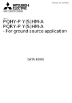
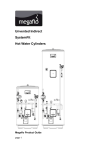
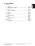
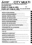
Air-Conditioners For Building Application INDOOR UNIT INSTALLATION MANUAL GB CMB-P-V-G1 CMB-P-V-GA1 (MAIN BC CONTROLLER) CMB-P-V-GB1 (SUBBC CONTROLLER) CMB-P-V-HA1 (MAIN BC CONTROLLER) CMB-P-V-HB1 (SUBBC CONTROLLER) INSTALLATIONSHANDBUCH D For safe and correct use, please read this installation manual thoroughly before installing the air-conditioner unit. MANUEL D’INSTALLATION F Zum sicheren und ordnungsgemäßen Gebrauch der Klimageräte das Installationshandbuch gründlich durchlesen. Voor een veilig en juist gebruik moet u deze installatiehandleiding grondig doorlezen voordat u de airconditioner installeert. MANUAL DE INSTALAÇÃO Para segurança e utilização correctas, leia atentamente este manual de instalação antes de instalar a unidade de ar condicionado. E°XEIPI¢IO O¢H°IøN E°KATA™TA™H™ °È· ·ÛÊ¿ÏÂÈ· Î·È ÛˆÛÙ‹ ¯Ú‹ÛË, ·Ú·Î·Ï›ÛÙ ‰È·‚¿ÛÂÙ ÚÔÛ¯ÙÈο ·˘Ùfi ÙÔ ÂÁ¯ÂÈÚ›‰ÈÔ ÂÁηٿÛÙ·Û˘ ÚÈÓ ·Ú¯›ÛÂÙ ÙËÓ ÂÁηٿÛÙ·ÛË Ù˘ ÌÔÓ¿‰·˜ ÎÏÈÌ·ÙÈÛÌÔ‡. РУКОВОДСТВО ПО УСТАНОВКЕ Для осторожного и правильного использования прибора необходимо тщательно ознакомиться с данным руководством по установке до выполнения установки кондиционера. MONTAJ ELK‹TABI I NL INSTALLATIEHANDLEIDING P Per un uso sicuro e corretto, leggere attentamente questo manuale di installazione prima di installare il condizionatore d’aria. GR MANUALE DI INSTALLAZIONE RU Para un uso seguro y correcto, lea detalladamente este manual de instalación antes de montar la unidad de aire acondicionado. TR MANUAL DE INSTALACIÓN E Veuillez lire le manuel d’installation en entier avant d’installer ce climatiseur pour éviter tout accident et vous assurer d’une utilisation correcte. РЪКОВОДСТВО ЗА МОНТАЖ За безопасна и правилна употреба, моля, прочетете внимателно това ръководство преди монтажа на климатизатора. BG Läs den här installationshandboken noga innan luftkonditioneringsenheten installeras, för säker och korrekt användning. RO INSTALLATIONSHANDBOK HR SW SL PO HG SV CZ Emniyetli ve do¤ru biçimde nas›l kullan›laca¤›n› ö¤renmek için lütfen klima cihaz›n› monte etmeden önce bu elkitab›n› dikkatle okuyunuz. 2 2.2 2.3 [Fig. 2.2.1] <A> Top view [Fig. 2.3.1] <B> Front view <A> 200 <B> B A (700) 250 450 C 130 B *1 D INDOOR UNIT SIDE 200 A Inspection hole B On the side of outdoor unit piping C Control box D On the side of indoor unit piping 100 B A *1 Dimensions with which pipe connection can be handled at site Model name CMB-P104V-G1 CMB-P105V-G1 CMB-P106V-G1 CMB-P108V-G1 CMB-P1010V-G1 CMB-P1013V-G1 CMB-P1016V-G1 CMB-P108V-GA1 CMB-P1010V-GA1 CMB-P1013V-GA1 CMB-P1016V-GA1 CMB-P104V-GB1 CMB-P108V-GB1 CMB-P1016V-HA1 CMB-P1016V-HB1 A B 648 - 1098 1110 200 648 - 1110 1098 200 - 2.4 [Fig. 2.4.1] CMB-P104, 105, 106, 108, 1010, 1013, 1016G1 (In the case the outdoor unit is 14-hp (P350 model) or less, and 16 or fewer ports are used.) A I A J H L h1 a C G b B M h2 C c D d e C C K C A Outdoor unit B BC controller C Indoor unit D P100 - P250 model: 2 ports merged. E Less than H=50 m (when the outdoor unit is higher than the indoor unit) F Less than H1=40 m (when the outdoor unit is lower than the indoor unit) G Twinning pipe (for Y Series) CMY-Y102S-G2 H Combined pipe (CMY-R160-J1: optional) I Less than 110 m K Up to three units for 1 branch hole Distance between BC controller and farthest indoor unit J Less than 40 m Total capacity: less than 80 (but same in cooling/heating mode) L Less than h1=15 m (10 m or less for 200, 250 unit type) M Less than h2=15 m Item A+B+a+b +c+d+e Length Total piping length Longest piping length Difference of elevation Between outdoor unit and BC controller Between indoor units and BC controller 2 Between indoor and outdoor units Piping portion A+e (Unit: m) Allowable value Not to exceed the maximum refrigerant piping length *1 165 m or less (Equivalent length of 190 m or less) A Below 110 e Below 40 *2 Above outdoor unit H Below 50 Below outdoor unit H1 Below 40 Between indoor units and BC controller h1 Between indoor units h2 Below 15 (Below 10)*3 Below 15 (Below 10)*3 Distance between BC contoroller and farthest indoor unit (m) EH F H1 B Notes: *1 Refer to “Restrictions on piping length” on P. 4. *2 Please refer to the figure “Distance between BC controller and farthest Indoor unit” when the distance between BC controller and farthest indoor unit exceeds 40 m. (Not applicable to the P250 model indoor unit) *3 The values in the parentheses show the maximum piping length to be followed when the connection capacity of the indoor unit is 200 or more. *4 In the system to which indoor units of the P200 model or above are connected, neither a branch joint nor a branch header may be used. *5 Do not connect the P200 or P250 models of indoor units and other models of indoor units at the same port. *6 In the system to which indoor units of the P100 through P140 models are connected, merge the two ports before connecting them. (Set DIP SW4-6 on the BC controller to ON.) *7 It is possible to connect the P100 through P140 models of indoor units to a single port. (Set DIP SW4-6 to OFF.) Note that the cooling capacity will somewhat decrease. (The factory setting for DIP SW4-6 is OFF.) *8 Indoor units that are connected to the same branch joint cannot be simultaneously operated in different operation modes. 70 60 50 40 30 20 10 0 0 5 10 15 Height difference between BC controller and farthest indoor unit (m) 2.4 [Fig. 2.4.2] CMB-P108, 1010, 1013, 1016GA1, P104, 108GB1 (GA1: In the case the outdoor unit is 26-hp (P650 model) or less.) CMB-P1016HA1, 1016HB1 (HA1: In the case the outdoor unit is 28-hp (P700 model) or more.) E A <System that has more than 16 branching points> F D G G D C N D H E C h2 LH M H1 I a C h3 B h1 e A B b c d D D D f *6 O F h1 h4 A K J A Outdoor unit B MAIN BC controller C SUB BC controller D Indoor unit E The twinning kit is connected inside the outdoor unit on the low-pressure side. Notes: A system that has more than 16 branching points requires 2 to 3 BC controllers (main and sub) and 3 pipes to connect the main and the sub BC controlWhen outdoor units of different capacities are connected, connect the twinning kit lers. to the unit with a higher capacity. *1 Refer to “Restrictions on piping length” on P. 4. F Twinning pipe (for R2 series) CMY-R100VBK, CMY-R200VBK *2 Please refer to the figure “Distance between main BC controller and far(for WR2 series) CMY-Q100VBK thest Indoor unit” when the distance between main BC controller and farthest indoor unit exceeds 40 m. (Not applicable to the P250 model G Twinning pipe (for Y series) CMY-Y202-G2, CMY-Y102L-G2, CMY-Y102S-G2 indoor unit) H Twinning pipe (CMY-R160-J1: optional) *3 The values in the parentheses show the maximum piping length to be I Twinning pipe (for Y series) CMY-Y102S-G2 followed when the connection capacity of the indoor unit is 200 or more. J P100 - P250 model: 2 ports merged *4 In the system to which indoor units of the P200 model or above are conK Maximum of 3 units per a pair of ports nected, neither a branch joint nor a branch header may be used. Total capacity of 80 or below *5 When connecting two sub BC controllers, the total piping length must be All units connected to the same port must be in the same operation mode. equal to or less than the maximum length as listed in on the left. L Less than H=50 m (when the outdoor unit is higher than the indoor unit) *6 When connecting two sub BC controllers, install them in parallel. M Less than H1=40 m (when the outdoor unit is lower than the indoor unit) *7 In the system to which indoor units of the P100 through P140 models are connected, merge the two ports before connecting them. (Set DIP SW4-6 N Less than h1=15 m (10 m or less for 200, 250 unit type) on the main BC controller to ON.) O Less than h2=15 m *8 It is possible to connect the P100 through P140 models of indoor units to a single port. (Set DIP SW4-6 to OFF.) Note that the cooling capacity will (Unit: m) somewhat decrease. (The factory setting for DIP SW4-6 is OFF.) Item Piping portion Allowable value *9 When the outdoor unit is 28-hp (P700 model) or more, use the HA-type Not to exceed the F+G+A+B+C main BC controller. The G-type BC controller cannot be connected to the maximum refrigerTotal piping length +D+E+a+b models between 16-hp (P400 model) and 26-hp (P650 model), and the Gant piping length *1 +c+d+e+f and GA-type BC controllers cannot be connected to the 28-hp (P650 165 m or less model) or more. *10 For Sub BC controller GB type, the connectable indoor unit capacities Longest piping length F(G)+A+C+E+f (Equivalent length may sum to equal that of a P350 unit or less. However, if two sub controlof 190 m or less) lers are used the TOTAL sum of connectable units connected to BOTH Between outdoor unit and F(G)+A Below 110 sub controllers must also not exceed that of a P350 unit. BC controller For sub BC controller HB type, the connectable indoor unit capacities Between indoor units and BC controller B+d or C+D+e or C+E+f Below 40 *2 may sum to equal that or a P350 unit or less. However, if two sub controlBetween outdoor units F+G Below 5 lers are used the TOTAL sum of connectable units connected to BOTH sub controllers must also not exceed that of a P450 unit. Between Above outdoor unit H Below 50 *11 Indoor units that are connected to the same branch joint cannot be siindoor and multaneously operated in different operation modes. outdoor units Below outdoor unit H1 Below 40 *12 Do not connect the P200 or P250 models of indoor units and other models of indoor units at the same port. Below 15 Between indoor units and BC controller h1 (Below 10)*3 Below 15 Distance between MAIN BC controller Between indoor units h2 and farthest indoor unit (Below 10)*3 Between BC controller (main or sub) 70 h3 Below 15 60 and BC controller (sub) 50 Between outdoor units h4 Below 0.1 Distance between MAIN BC controller and farthest indoor unit (m) Difference of elevation Length D 40 30 20 10 0 0 5 10 15 Height difference between MAIN BC controller and farthest indoor unit (m) 3 2.4 [Fig. 2.4.3] ●Restrictions on piping length PURY-P600/650YSHM-A, PURY-EP600YSHM-A 1000 1000 900 900 800 800 700 700 A A PURY-P200/250/300YHM-A, PURY-EP200YHM-A PQRY-P200/250/300YHM-A 600 600 500 500 400 400 300 300 200 200 10 20 30 40 50 60 70 80 90 100 110 10 20 30 40 50 B 70 80 90 100 110 70 80 90 100 110 B PURY-P350/400/450Y(S)HM-A, PURY-EP250/300YHM-A PURY-P700/750/800YSHM-A 1000 1000 900 900 800 800 700 700 A A 60 600 600 500 500 400 400 300 300 200 200 10 20 30 40 50 60 70 80 90 100 110 10 20 30 40 50 B 60 B PURY-P500/550YSHM-A, PURY-EP400/450/500/550YSHM-A(1) PQRY-P400/450/500/550/600YSHM-A 1000 900 800 A 700 600 500 400 300 200 10 20 30 40 50 60 70 80 90 100 110 B A Total piping length (m) B Piping length between outdoor unit and BC controller (m) 3 3.2 [Fig. 3.2.1] 14 A A 30 B 1 4 (Top view) 1 Hanging method A: Min. 30 mm A Hanging bolt ø10 (field supply) B Washer (field supply) 4 4.1 [Fig. 4.1.1] A A Indoor unit connecting port B Cutting point : ø9.52 (Liquid side) or ø15.88 (Gas side) (Indoor unit model : bigger than P50) C C B Cutting point : ø6.35 (Liquid side) or ø12.7 (Gas side) (Indoor unit model : P50 or smaller) D D Cut the piping at the cutting point E Have pipe expansion of indoor unit connecting port F Field pipe Note: Remove burr after cutting the piping to prevent entering the piping. Check that there is no crack at the pipe expansion part. E A A F F [Fig. 4.1.2] BC CONTROLLER/MAIN BC CONTROLLER High pressure Low pressure side side ø15.88*1 ø19.05*1 (BC CONTROLLER) (Brazing) (Brazing) CMB-P104V-G1 CMB-P105V-G1 CMB-P106V-G1 ø22.2 ø19.05 CMB-P108V-G1 (Brazing) (Brazing) CMB-P1010V-G1 CMB-P1013V-G1 ø28.58*1 CMB-P1016V-G1 (Brazing) ø19.05*1 (Brazing) Unit model Model name Outdoor unit side PURY-(E) P200 PQRY-P200 PURY-(E) P250 PQRY-P250 PURY-(E) P300 PQRY-P300 PURY-P350 PURY-(E) P400 PQRY-P400 PURY-(E) P450 PQRY-P450 PURY-(E) P500 PQRY-P500 PURY-(E) P550 PQRY-P550 PURY-(E) P600 PQRY-P600 PURY-P650 PURY-P700 PURY-P750 PURY-P800 (MAIN BC CONTROLLER) CMB-P108V-GA1 CMB-P1010V-GA1 CMB-P1013V-GA1 CMB-P1016V-GA1 Model name SUB BC CONTROLLER Total capacity High pressure Low pressure of indoor units (gas) side (gas) side When a system that has more than 16 branching points, use BC controllers (main and sub) to connect the pipes. ø22.2 (Brazing) below 200 ø28.58 (Brazing) ø28.58*1 (Brazing) ø15.88*1 (Brazing) ø19.05*1 (Brazing) ø9.52 (Brazing) CMB-P104V-GB1 CMB-P108V-GB1 CMB-P1016V-HB1 ø22.2 (Brazing) 201~300 ø19.05 (Brazing) 301~350 (MAIN BC CONTROLLER) CMB-P1016V-HA1 351~400 ø34.93*1 (Brazing) ø28.58 (Brazing) 401~450 ø9.52 or ø6.35 ø15.88 or ø12.7 (Brazing) (Brazing) Indoor unit side Liquid side ø22.2*1 (Brazing) ø28.58*1 (Brazing) ø12.7*1 (Brazing) ø15.88*1 (Brazing) ø9.52 or ø6.35 ø15.88 or ø12.7 (Brazing) (Brazing) *1 Use the supplied pipe. Total capacity of indoor units Below 140 141 to 200 201 to 250 A B C *1D E E F H G*2 63-80 E E 100-250 *3 E E I A To outdoor unit (MAIN BC CONTROLLER) B End connection (brazing) C BC controller (MAIN BC CONTROLLER / SUB BC CONTROLLER) D Reducer F Less than 50 G Combined piping kit (Model name: CMY-R160-J1) H Twinning pipe (Model name: CMY-Y102S-G2) I Up to three units for 1 branch hole; total capacity: below 80 (but same in cooling/ heating mode) E Indoor unit Liquid line ø9.52 Gas line ø15.88 ø19.05 ø22.2 *1. For connecting 15 to 50 type indoor units Have pipe expansion of indoor unit connecting port by cutting the piping at the cutting point which depends on the indoor unit capacity. Note: Remove burr after cutting the piping to prevent entering the piping. Check that there is no crack at the pipe expansion part. *2. To connect a unit with a capacity of higher than 81. After combining two branches using an optionally available piping kit (CMY-R160J1), connect indoor units. *3. Connection of plural indoor units with one connection (or joint pipe) • Total capacity of connectable indoor units: Less than 80 (Less than 250 with joint pipe) • Number of connectable indoor units: Maximum 3 Sets • Twinning pipe: Use the twinning pipe for CITY MULTI Y Series (CMY-Y102S-G2) • Selection of refrigerant piping Select the size according to the total capacity of indoor units to be installed downstream. 5 4.2 4.3 [Fig. 4.2.1] [Fig. 4.3.1] A Cut here B Remove brazed cap C B A A D B E F A Locally procured insulating material for pipes B Bind here using band or tape. c Do not leave any opening. D Lap margin: more than 40 E Insulating material (field supply) F Unit side insulating material 4.4 [Fig. 4.4.1] C A 1 D E F [Fig. 4.4.2] A B A B VP-30 B VP-25 G B D 2 5 B: C A: 25 cm 1.5 – 2 m A Downward pitch of more than 1/100 B Insulating material C Supporting bracket D Drain discharge port E Drain hose (200 mm long, accessory) A BC controller B Indoor unit F Tie band (accessory) G Hose band (accessory) C Collecting pipe D Please ensure this length is at least 10 cm. [Fig. 5.0.1] A B C D 6 A Control box B Power source wiring C ø21 hole (closed rubber bushing) D Transmission wiring 3 Contents 1. Safety precautions ...................................................................................... 1.1. Before installation and electric work .......................................... 1.2. Precautions for devices that use R410A refrigerant .................. 1.3. Before installation ...................................................................... 1.4. Before installation (relocation) - electrical work ......................... 1.5. Before starting the test run ........................................................ 2. Selecting an installation site ....................................................................... 2.1. About the product ...................................................................... 2.2. Installation site ........................................................................... 2.3. Securing installation and service space .................................... 2.4. Checking the installation site ..................................................... 7 7 7 8 8 8 8 8 8 9 9 3. Installing BC controller .............................................................................. 3.1. Checking the accessories with BC controller .......................... 3.2. Installing BC controllers ........................................................... 4. Connecting refrigerant pipes and drain pipes ........................................... 4.1. Connecting refrigerant pipes ................................................... 4.2. Refrigerant piping work ........................................................... 4.3. Insulating refrigerant pipes ...................................................... 4.4. Drain piping work ..................................................................... 5. Electrical work ........................................................................................... 6. Setting addresses and operating units ..................................................... 7. Test run ..................................................................................................... 10 10 10 10 10 11 12 12 12 12 12 : Indicates an action that must be avoided. • : Indicates a part which must be grounded. • Warning: Carefully read the labels affixed to the main unit. • HIGH VOLTAGE WARNING: • • • Control box houses high-voltage parts. When opening or closing the front panel of the control box, do not let it come into contact with any of the internal components. Before inspecting the inside of the control box, turn off the power, keep the unit off for at least 10 minutes. Warning: • • • • • • • • Ask the dealer or an authorized technician to install the air conditioner. - Improper installation by the user may result in water leakage, electric shock, or fire. Install the unit at a place that can withstand its weight. - Failure to do so may cause the unit to fall down, resulting in injuries and damage to the unit. Use the specified cables for wiring. Make the connections securely so that the outside force of the cable is not applied to the terminals. - Inadequate connection and fastening may generate heat and cause a fire. Prepare for earthquakes and install the unit at the specified place. - Improper installation may cause the unit to fall down and result in injury and damage to the unit. Always use accessories specified by Mitsubishi Electric. - Ask an authorized technician to install the accessories. Improper installation by the user may result in water leakage, electric shock, or fire. Never repair the unit. If the air conditioner must be repaired, consult the dealer. - If the unit is repaired improperly, water leakage, electric shock, or fire may result. If refrigerant gas leaks during installation work, ventilate the room. - If the refrigerant gas comes into contact with a flame, poisonous gases will be released. Install the air conditioner according to this Installation Manual. - If the unit is installed improperly, water leakage, electric shock, or fire may result. • • • D F E 1.2. Precautions for devices that use R410A refrigerant Caution: • • • • Do not use existing refrigerant piping. - The old refrigerant and refrigerant oil in the existing piping contains a large amount of chlorine which may cause the refrigerant oil of the new unit to deteriorate. - R410A is a high-pressure refrigerant and can cause the existing piping to burst. Use refrigerant piping made of phosphorus deoxidized copper and copper alloy seamless pipes and tubes. In addition, be sure that the inner and outer surfaces of the pipes are clean and free of hazardous sulphur, oxides, dust/dirt, shaving particles, oils, moisture, or any other contaminant. - Contaminants on the inside of the refrigerant piping may cause the refrigerant residual oil to deteriorate. Store the piping to be used during installation indoors and keep both ends of the piping sealed until just before brazing. (Store elbows and other joints in a plastic bag.) - If dust, dirt, or water enters the refrigerant cycle, deterioration of the oil and compressor failure may result. Apply a small amount of ester oil, ether oil, or alkyl benzene to flares. (for indoor unit) - Infiltration of a large amount of mineral oil may cause the refrigerant oil to deteriorate. 7 CZ : Beware of electric shock (This symbol is displayed on the main unit label.) <Color: Yellow> SV : Indicates that important instructions must be followed. I Symbols used in the illustrations NL • SL Caution: Describes precautions that should be observed to prevent damage to the unit. P Describes precautions that should be observed to prevent danger of injury or death to the user. GR • Warning: RU Symbols used in the text TR • Have all electric work done by a licensed electrician according to “Electric Facility Engineering Standard” and “Interior Wire Regulations”and the instructions given in this manual and always use a dedicated power supply. - If the power source capacity is inadequate or electric work is performed improperly, electric shock and fire may result. Securely install the cover of control box. - If the cover is not installed properly, dust or water may enter the outdoor unit and fire or electric shock may result. When installing and moving the air conditioner to another site, do not charge it with a refrigerant different from the refrigerant specified on the unit. - If a different refrigerant or air is mixed with the original refrigerant, the refrigerant cycle may malfunction and the unit may be damaged. If the air conditioner is installed in a small room, measures must be taken to prevent the refrigerant concentration from exceeding the safety limit if the refrigerant should leak. - Consult the dealer regarding the appropriate measures to prevent the safety limit from being exceeded. Should the refrigerant leak and cause the safety limit to be exceeded, hazards due to lack of oxygen in the room could result. When moving and reinstalling the air conditioner, consult the dealer or an authorized technician. - If the air conditioner is installed improperly, water leakage, electric shock, or fire may result. After completing installation work, make sure that refrigerant gas is not leaking. - If the refrigerant gas leaks and is exposed to a fan heater, stove, oven, or other heat source, it may generate noxious gases. Do not reconstruct or change the settings of the protection devices. - If the pressure switch, thermal switch, or other protection device is shorted or operated forcibly, or parts other than those specified by Mitsubishi Electric are used, fire or explosion may result. To dispose of this product, consult your dealer. The installer and system specialist shall secure safety against leakage according to local regulation or standards. - Choose the appropriate wire size and the switch capacities for the main power supply described in this manual if local regulations are not available. Pay special attention to the place of installation, such as basement, etc. where refrigeration gas can accumulate, since refrigerant is heavier than the air. HG s Before installing the unit, make sure you read all the “Safety precautions”. s The “Safety precautions” provide very important points regarding safety. Make sure you follow them. • PO 1.1. Before installation and electric work GB 1. Safety precautions • • • • • • D GB • Use liquid refrigerant to fill the system. - If gas refrigerant is used to fill the system, the composition of the refrigerant in the cylinder will change and performance may drop. Do not use a refrigerant other than R410A. - If another refrigerant (R22, etc.) is mixed with R410A, the chlorine in the refrigerant may cause the refrigerant oil to deteriorate. Use a vacuum pump with a reverse flow check valve. - The vacuum pump oil may flow back into the refrigerant cycle and cause the refrigerant oil to deteriorate. Do not use the following tools that are used with conventional refrigerants. (Gauge manifold, charge hose, gas leak detector, reverse flow check valve, refrigerant charge base, refrigerant recovery equipment) - If the conventional refrigerant and refrigerant oil are mixed in the R410A, the refrigerant may deteriorate. - If water is mixed in the R410A, the refrigerant oil may deteriorate. - Since R410A does not contain any chlorine, gas leak detectors for conventional refrigerants will not react to it. Do not use a charging cylinder. - Using a charging cylinder may cause the refrigerant to deteriorate. Do not use antioxidant or leak-detection additive. Be especially careful when managing the tools. - If dust, dirt, or water gets into the refrigerant cycle, the refrigerant may deteriorate. 1.4. Before installation (relocation) - electrical work Caution: • • • • • • • • F 1.3. Before installation Caution: E • • I • • GR P NL • Do not install the unit where combustible gas may leak. - If the gas leaks and accumulates around the unit, an explosion may result. Do not use the air conditioner where food, pets, plants, precision instruments, or artwork are kept. - The quality of the food, etc. may deteriorate. Do not use the air conditioner in special environments. - Oil, steam, sulfuric smoke, etc. can significantly reduce the performance of the air conditioner or damage its parts. When installing the unit in a hospital, communication station, or similar place, provide sufficient protection against noise. - Inverter equipment, private power generator, high-frequency medical equipment, or radio communication equipment may cause the air conditioner to operate erroneously, or fail to operate. On the other hand, the air conditioner may affect such equipment by creating noise that disturbs medical treatment or image broadcasting. Do not install the unit on or over things that are subject to water damage. - When the room humidity exceeds 80 % or when the drain pipe is clogged, condensation may drip from the indoor unit or BC controller. Perform collective drainage work together with the outdoor unit, as required. • • 1.5. Before starting the test run Caution: • • RU • • TR Ground the unit. - Do not connect the ground wire to gas or water pipes, lightning rods, or telephone ground lines. Improper grounding may result in electric shock. Install the power cable so that tension is not applied to the cable. - Tension may cause the cable to break and generate heat and cause a fire. Install a leak circuit breaker, as required. - If a leak circuit breaker is not installed, electric shock may result. Use power line cables of sufficient current carrying capacity and rating. - Cables that are too small may leak, generate heat, and cause a fire. Use only a circuit breaker and fuse of the specified capacity. - A fuse or circuit breaker of a larger capacity, or the use of substitute simple steel or copper wire may result in a general unit failure or fire. Do not wash the air conditioner units. - Washing them may cause an electric shock. Be careful that the installation base is not damaged by long use. - If the damage is left uncorrected, the unit may fall and cause personal injury or property damage. Install the drain piping according to this Installation Manual to ensure proper drainage. Wrap thermal insulation around the pipes to prevent condensation. - Improper drain piping may cause water leakage causing damage to furniture and other possessions. Be very careful about transporting the product. - One person should not carry the product. Its weight is in excess of 20 kg. - Some products use PP bands for packaging. Do not use any PP bands as a means of transportation. It is dangerous. Safely dispose of the packing materials. - Packing materials, such as nails and other metal or wooden parts, may cause stabs or other injuries. - Tear apart and throw away plastic packaging bags so that children will not play with them. If children play with a plastic bag which has not been torn apart, they face the risk of suffocation. • Turn on the power at least 12 hours before starting operation. - Starting operation immediately after turning on the main power switch can result in irreversible damage to internal parts. Keep the power switch turned on during the operational season. Do not touch the switches with wet fingers. - Touching a switch with wet fingers can result in an electric shock. Do not touch the refrigerant pipes during and immediately after operation. - During and immediately after operation, the refrigerant pipes may be hot or cold, depending on the condition of the refrigerant flowing through the refrigerant piping, compressor, and other refrigerant cycle parts. Your hands may suffer burns or frostbite if you touch the refrigerant pipes. Do not operate the air conditioner with the panels and guards removed. - Rotating, hot, or high-voltage parts can cause injuries. Do not turn off the power immediately after stopping operation. - Always wait at least 5 minutes before turning off the power. Otherwise, drainage water leakage or mechanical failure of sensitive parts may occur. 2.1. About the product 2.2. Installation site • • • Install the unit in a place not exposed to rain. The BC controller is designed to be installed indoors. • Install the unit with adequate space around it for servicing. • Do not install the unit in a place that would result in the piping length restrictions being exceeded. • Install the unit in a place not exposed to direct radiant heat from other heat sources. • Do not install the unit in any oily steamy place or near any machine that generates high frequencies. Doing so may cause a risk of fire, erroneous operation or dew drop. • Install the unit in a location where the noise from the unit will not be a problem. (Install indoor unit and BC controller at least 5 m away from each other when installed in a space with low background noise, e.g., hotel rooms). • Allow enough space and access to ensure water piping, refrigerant piping and electrical wiring can be easily connected. • Avoid places exposed to the generation, inflow, accumulation or leakage of flammable and sulfuric gases. • Ensure a downward gradient of at least 1/100 for drain piping. • Properly install the unit on a stable, load-bearing surface. Some of the tools and equipment used for installation with systems that use other types of refrigerant cannot be used with the systems using R410A. Refer to the Data Book for more information. • Do not use the existing piping, as it contains chlorine, which is found in conventional refrigerating machine oil and refrigerant. This chlorine will deteriorate the refrigerant machine oil in the new equipment. The existing piping must not be used as the design pressure in systems using R410A is higher than that in the systems using other types of refrigerant and the existing pipes may burst. PO HG This unit uses R410A-type refrigerant. Piping for systems using R410A may be different from that for systems using conventional refrigerant because the design pressure in systems using R410A is higher. Refer to the Data Book for more information. • SL SV CZ 2. Selecting an installation site 8 • Be sure to install the BC controller horizontally. 2.3. Securing installation and service space 1. For hanging from the ceiling (This is a reference view showing the least installation space.) [Fig. 2.3.1] (P.2) <B> Front view A Inspection hole B On the side of outdoor unit piping C Control box D On the side of indoor unit piping *1 Dimensions with which pipe connection can be handled at site B 648 - 1098 200 - Below 50 Below outdoor unit H1 Below 40 Between indoor units and BC controller h1 Between indoor units h2 Below 15 (Below 10)*3 Below 15 (Below 10)*3 Notes: *1 Refer to “Restrictions on piping length” on P. 4. *2 Please refer to the figure “Distance between BC controller and farthest Indoor unit” when the distance between BC controller and farthest indoor unit exceeds 40 m. (Not applicable to the P250 model indoor unit) *3 The values in the parentheses show the maximum piping length to be followed when the connection capacity of the indoor unit is 200 or more. *4 In the system to which indoor units of the P200 model or above are connected, neither a branch joint nor a branch header may be used. *5 Do not connect the P200 or P250 models of indoor units and other models of indoor units at the same port. *6 In the system to which indoor units of the P100 through P140 models are connected, merge the two ports before connecting them. (Set DIP SW4-6 on the BC controller to ON.) *7 It is possible to connect the P100 through P140 models of indoor units to a single port. (Set DIP SW4-6 to OFF.) Note that the cooling capacity will somewhat decrease. (The factory setting for DIP SW4-6 is OFF.) *8 Indoor units that are connected to the same branch joint cannot be simultaneously operated in different operation modes. Distance between BC controller and farthest indoor unit 2.4. Checking the installation site Check that the difference of elevation between indoor and outdoor units and the length of refrigerant piping are within the following limitations. 1. CMB-P104, 105, 106, 108, 1010, 1013, 1016G1 (In the case the outdoor unit is 14-hp (P350 model) or less, and 16 or fewer ports are used.) [Fig. 2.4.1] (P.2) 70 60 50 40 30 20 10 0 P 1110 1098 H GR - Above outdoor unit 0 RU 648 Below 40 *2 5 10 15 Height difference between BC controller and farthest indoor unit (m) TR 200 e A Outdoor unit B BC controller C Indoor unit D P100 - P250 model: 2 ports merged. E Less than H=50 m (when the outdoor unit is higher than the indoor unit) F Less than H1=40 m (when the outdoor unit is lower than the indoor unit) G Twinning pipe (for Y Series) CMY-Y102S-G2 H Combined pipe (CMY-R160-J1: optional) I Less than 110 m A Outdoor unit B MAIN BC controller K Up to three units for 1 branch hole C SUB BC controller D Indoor unit Total capacity: less than 80 (but same in cooling/heating mode) E The twinning kit is connected inside the outdoor unit on the low-pressure side. L Less than h1=15 m (10 m or less for 200, 250 unit type) M Less than h2=15 m CZ [Fig. 2.4.2] (P.3) Less than 40 m When outdoor units of different capacities are connected, connect the twinning kit to the unit with a higher capacity. F Twinning pipe (for R2 series) CMY-R100VBK, CMY-R200VBK G Twinning pipe (for Y series) CMY-Y202-G2, CMY-Y102L-G2, CMY-Y102S-G2 H Twinning pipe (CMY-R160-J1: optional) I Twinning pipe (for Y series) CMY-Y102S-G2 J P100 - P250 model: 2 ports merged K Maximum of 3 units per a pair of ports (for WR2 series) CMY-Q100VBK HG J 2. CMB-P108, 1010, 1013, 1016GA1, P104, 108GB1 (GA1: In the case the outdoor unit is 26-hp (P650 model) or less.) CMB-P1016HA1, 1016HB1 (HA1: In the case the outdoor unit is 28-hp (P700 model) or more.) SV 1110 Below 110 SL A A Total capacity of 80 or below All units connected to the same port must be in the same operation mode. L Less than H=50 m (when the outdoor unit is higher than the indoor unit) M Less than H1=40 m (when the outdoor unit is lower than the indoor unit) N Less than h1=15 m (10 m or less for 200, 250 unit type) O Less than h2=15 m 9 PO Model name CMB-P104V-G1 CMB-P105V-G1 CMB-P106V-G1 CMB-P108V-G1 CMB-P1010V-G1 CMB-P1013V-G1 CMB-P1016V-G1 CMB-P108V-GA1 CMB-P1010V-GA1 CMB-P1013V-GA1 CMB-P1016V-GA1 CMB-P104V-GB1 CMB-P108V-GB1 CMB-P1016V-HA1 CMB-P1016V-HB1 Between indoor and outdoor units Distance between BC contoroller and farthest indoor unit (m) <A> Top view Difference of elevation Caution: Be sure to install the unit horizontally. A+e Between outdoor unit and BC controller Between indoor units and BC controller Warning: Be sure to install the unit in a place that can sustain the entire weight. If there is a lack of strength, it may cause the unit to fall down, resulting in an injury. Longest piping length GB Ensure a pull out strength of at least 60 kg per bolt for hanging bolts. D • A+B+a+b +c+d+e Total piping length (Unit: m) Allowable value Not to exceed the maximum refrigerant piping length *1 165 m or less (Equivalent length of 190 m or less) F Install the unit in a suitable location (such as in the ceiling of a corridor or in the bathroom etc) away from places regularly occupied. Avoid installing in the center of a room. Piping portion E • Item I Provide an inspection hole 450 mm square in the ceiling surface as shown in [Fig. 2.3.1] (P.2). Length • NL 1. For hanging from the ceiling [Fig. 2.2.1] (P.2) Piping portion F+G+A+B+C +D+E+a+b +c+d+e+f Length Total piping length Longest piping length F(G)+A+C+E+f (Unit: m) Allowable value Not to exceed the maximum refrigerant piping length *1 165 m or less (Equivalent length of 190 m or less) Difference of elevation Between indoor and outdoor units Below 110 Below 40 *2 Below 5 Above outdoor unit H Below 50 Below outdoor unit H’ Below 40 Between indoor units and BC controller h1 Between indoor units h2 Between BC controller (main or sub) and BC controller (sub) Between outdoor units Below 15 (Below 10)*3 Below 15 (Below 10)*3 h3 Below 15 h4 Below 0.1 Notes: A system that has more than 16 branching points requires 2 to 3 BC controllers (main and sub) and 3 pipes to connect the main and the sub BC controllers. *1 Refer to “Restrictions on piping length” on P. 4. *2 Please refer to the figure “Distance between main BC controller and farthest Indoor unit” when the distance between main BC controller and farthest indoor unit exceeds 40 m. (Not applicable to the P250 model indoor unit) *3 The values in the parentheses show the maximum piping length to be followed when the connection capacity of the indoor unit is 200 or more. *4 In the system to which indoor units of the P200 model or above are connected, neither a branch joint nor a branch header may be used. *5 When connecting two sub BC controllers, the total piping length must be equal to or less than the maximum length as listed in on the left. *6 When connecting two sub BC controllers, install them in parallel. GR 3.1. Checking the accessories with BC controller The following items are supplied with each BC controller. CMBP104V-G1 P105V-G1 P106V-G1 P108V-G1 P1010V-G1 P1013V-G1 P1016V-G1 TR CZ SV Distance between MAIN BC controller and farthest indoor unit 70 60 50 40 30 20 10 0 0 5 10 15 Height difference between MAIN BC controller and farthest indoor unit (m) [Fig. 2.4.3] (P.4) A Total piping length (m) B Piping length between controller unit and BC controller (m) 3. Installing BC controller RU P NL I E F D GB Between outdoor unit and F(G)+A BC controller Between indoor units and BC controller B+d or C+D+e or C+E+f Between outdoor units F+G *7 In the system to which indoor units of the P100 through P140 models are connected, merge the two ports before connecting them. (Set DIP SW4-6 on the BC controller to ON.) *8 It is possible to connect the P100 through P140 models of indoor units to a single port. (Set DIP SW4-6 to OFF.) Note that the cooling capacity will somewhat decrease. (The factory setting for DIP SW4-6 is OFF.) *9 When the outdoor unit is 28-hp (P700 model) or more, use the HA-type main BC controller. The G-type BC controller cannot be connected to the models between 16-hp (P400 model) and 26-hp (P650 model), and the Gand GA-type BC controllers cannot be connected to the 28-hp (P650 model) or more. *10 For Sub BC controller GB type, the connectable indoor unit capacities may sum to equal that of a P350 unit or less. However, if two sub controllers are used the TOTAL sum of connectable units connected to BOTH sub controllers must also not exceed that of a P350 unit. For sub BC controller HB type, the connectable indoor unit capacities may sum to equal that or a P350 unit or less. However, if two sub controllers are used the TOTAL sum of connectable units connected to BOTH sub controllers must also not exceed that of a P450 unit. *11 Indoor units that are connected to the same branch joint cannot be simultaneously operated in different operation modes. *12 Do not connect the P200 or P250 models of indoor units and other models of indoor units at the same port. Distance between MAIN BC controller and farthest indoor unit (m) Item 1 2 3 4 Item Drain hose Tie band Hose band Refrigerant connection pipe Model name CMBCMBCMBCMBP108V-GA1 P104V-GB1 P1016V-HA1 P1016V-HB1 P1010V-GA1 P108V-GB1 P1013V-GA1 P1016V-GA1 3.2. Installing BC controllers Installing hanging bolts Install locally procured hanging bolts (threaded rod) following the procedure given in the figure. The hanging bolt size is ø10 (M10 screw). To hang the unit, use a lifting machine to lift and pass it through the hanging bolts. Suspension bracket has an oval hole. Use a large diameter washer. [Fig. 3.2.1] (P.4) 1 A: Min.30 mm A 1 1 1 1 1 1 Qty 1 1 1 3 3 8 1 1 1 1 1 1 1 8 Hanging method Hanging bolt ø10 (field supply) B Washer (field supply) s Be sure to install the BC controller horizontally, using a level. If the controller is installed at an angle, drain water may leak out. If the controller is slanted, loosen the fixing nuts on the hanging brackets to adjust its position. Caution: Be sure to install the unit horizontally. PO HG SL 4. Connecting refrigerant pipes and drain pipes 4.1. Connecting refrigerant pipes 1. Connect the liquid and gas pipes of each indoor unit to the same (correct) end connection numbers as indicated on the indoor unit connection section of each BC controller. If connected to wrong end connection numbers, there will be no normal operation. 2. List indoor unit model names in the name plate on the BC controller control box (for identification purposes), and BC controller end connection numbers and address numbers in the name plate on the indoor unit side. 3. If the number of ports is greater than the number of indoor units to be connected, use any ports. Seal unused end connections using cover caps just as they were capped when shipped from the factory. Not replacing on end cap will lead to refrigerant leak-age. 4. When using CMY-Y102S-G2, CMY-Y102L-G2, or CMY-Y202-G2, connect it horizontally. 10 5. Be sure to have pipe expansion of indoor unit connecting port by cutting the piping at the cutting point which depends on the indoor unit capacity. Note: Remove burr after cutting the piping to prevent entering the piping. Check that there is no crack at the pipe expansion part. [Fig. 4.1.1] (P.5) A Indoor unit connecting port B Cutting point : ø9.52 (Liquid side) or ø15.88 (Gas side) (Indoor unit model : bigger than P50) C Cutting point : ø6.35 (Liquid side) or ø12.7 (Gas side) (Indoor unit model : P50 or smaller) D Cut the piping at the cutting point E Have pipe expansion of indoor unit connecting port F Field pipe 7. After completing pipe connection, support the pipes to ensure that load is not imparted to the BC controller’s end connections (particularly to the gas pipes of indoor units). Caution: • • • Warning : When installing and moving the unit, do not charge it with refrigerant other than the refrigerant (R410A) specified on the unit. - Mixing of a different refrigerant, air, etc. may cause the refrigerant cycle to malfunction and result in severe damage. SUB BC CONTROLLER Total capacity High pressure Low pressure of indoor units (gas) side (gas) side Liquid side D Model name F When a system that has more than 16 branching points, use BC controllers (main and sub) to connect the pipes. E Outdoor unit side I ø19.05*1 (Brazing) ø9.52 (Brazing) NL ø19.05 (Brazing) 401~450 ø22.2*1 (Brazing) ø12.7*1 (Brazing) ø15.88*1 (Brazing) ø9.52 or ø6.35 ø15.88 or ø12.7 (Brazing) (Brazing) *1 Use the supplied pipe. B C D F G H I End connection (brazing) BC controller (MAIN BC CONTROLLER/SUB BC CONTROLLER) Reducer E Indoor unit Less than 50 Combined piping kit (Model name: CMY-R160-J1) Twinning pipe (Model name: CMY-Y102S-G2) Up to three units for 1 branch hole; total capacity: below 80 (but same in cooling/ heating mode) The size of BC controller’s branch piping is for 63 to 140 type indoor units. Therefore, if you want to connect indoor units other than the above, connect piping following the procedures below. *1. For connecting 15 to 50 type indoor units Have pipe expansion of indoor unit connecting port by cutting the piping at the cutting point which depends on the indoor unit capacity. Note: Remove burr after cutting the piping to prevent entering the piping. Check that there is no crack at the pipe expansion part. *2. To connect a unit with a capacity of higher than 81. After combining two branches using an optionally available piping kit (CMY-R160J1), connect indoor units. *3. Connection of plural indoor units with one connection (or joint pipe) • Total capacity of connectable indoor units: Less than 80 (Less than 250 with joint pipe) • Number of connectable indoor units: Maximum 3 Sets • Twinning pipe: Use the twinning pipe for CITY MULTI Y Series (CMY-Y102SG2) • Selection of refrigerant piping Select the size according to the total capacity of indoor units to be installed downstream. Total capacity of indoor units Below 140 141 to 200 201 to 250 Liquid line ø9.52 Note: Be sure to use non-oxidative brazing. RU To outdoor unit (MAIN BC CONTROLLER) 4.2. Refrigerant piping work After connecting the refrigerant pipes of all indoor and outdoor units with the outdoor units’ stop valves remained fully closed, evacuate vacuum from the outdoor units’ stop valve service ports. After completing the above, open the outdoor units’ stop valves. This connects the refrigerant circuit (between outdoor and BC controller) completely. How to handle stop valves is described on each outdoor unit. Notes: • After pipe connection, be sure to check that there is no gas leakage, using a leak detector or soap-and-water solution. • Before brazing the refrigerant piping, always wrap the piping on the main body, and the thermal insulation piping, with damp cloths to prevent heat shrinkage and burning the thermal insulation tubing. Take care to ensure that the flame does not come into contact with the main body itself. • Do not use leak-detection additives. Warning: Do not mix anything other than the specified refrigerant (R410A) into the refrigerating cycle when installing or moving. Mixing air may cause the refrigerating cycle to reach abnormally high temperature, resulting in burst pipes. Caution: Cut the tip of the outdoor unit piping, remove the gas, and then remove the brazed cap. [Fig. 4.2.1] (P.6) A Cut here B Remove brazed cap PO A GR 351~400 ø28.58*1 (Brazing) P 301~350 TR 201~300 CZ CMB-P104V-GB1 CMB-P108V-GB1 CMB-P1016V-HB1 ø22.2 (Brazing) SV ø15.88*1 (Brazing) SL below 200 HG 1. Size of BC controller’s end connection piping [Fig. 4.1.2] (P.5) BC CONTROLLER/MAIN BC CONTROLLER High pressure Low pressure Unit model Model name side side ø19.05*1 ø15.88*1 PURY-(E) P200 (BC CONTROLLER) (Brazing) (Brazing) CMB-P104V-G1 PQRY-P200 PURY-(E) P250 CMB-P105V-G1 CMB-P106V-G1 PQRY-P250 ø22.2 ø19.05 (Brazing) PURY-(E) P300 CMB-P108V-G1 (Brazing) CMB-P1010V-G1 PQRY-P300 CMB-P1013V-G1 ø28.58*1 CMB-P1016V-G1 PURY-P350 (Brazing) ø19.05*1 (Brazing) PURY-(E) P400 PQRY-P400 (MAIN BC PURY-(E) P450 ø22.2 CONTROLLER) (Brazing) PQRY-P450 CMB-P108V-GA1 PURY-(E) P500 CMB-P1010V-GA1 ø28.58 PQRY-P500 (Brazing) CMB-P1013V-GA1 PURY-(E) P550 CMB-P1016V-GA1 PQRY-P550 ø28.58*1 PURY-(E) P600 (Brazing) PQRY-P600 PURY-P650 PURY-P700 (MAIN BC ø34.93*1 ø28.58 PURY-P750 CONTROLLER) (Brazing) (Brazing) PURY-P800 CMB-P1016V-HA1 ø9.52 or ø6.35 ø15.88 or ø12.7 Indoor unit side (Brazing) (Brazing) • • Use refrigerant piping made of phosphorus deoxidized copper and copper alloy seamless pipes and tubes. In addition, be sure that the inner and outer surfaces of the pipes are clean and free of hazardous sulphur, oxides, dust/dirt, shaving particles, oils, moisture, or any other contaminant. - R410A is a high-pressure refrigerant and can cause the existing piping to burst. Store the piping to be used during installation indoors and keep both ends of the piping sealed until just before brazing. (Store elbows and other joints in a plastic bag.) - If dust, dirt, or water enters the refrigerant cycle, deterioration of the oil and compressor failure may result. Apply a small amount of ester oil, ether oil, or alkyl benzene to flares. (for indoor unit) - Infiltration of a large amount of mineral oil may cause the refrigerant oil to deteriorate. Do not vent R410A into the atmosphere. R410A is a Fluorinated Greenhouse gas, covered by the Kyoto Protocol with a Global Warming Potential (GWP) = 1975. GB 6. Be sure to use non-oxidative brazing where necessary. If you do not use nonoxidative brazing, it may clog the pipes. While under a nitrogen purge, braze the indoor unit connecting port before brazing the outdoor unit connecting port of BC controller. When brazing the indoor unit connecting port, supply a nitrogen gas into the outdoor unit connecting port of BC controller. When brazing the outdoor unit connecting port of BC controller, supply a nitrogen gas into the pipe between the outdoor unit and BC controller. Gas line ø15.88 ø19.05 ø22.2 11 4.3. Insulating refrigerant pipes Be sure to add insulation work to refrigerant piping by covering high-pressure pipe and low-pressure pipe separately with enough thickness heat-resistant polyethylene, so that no gap is observed in the joint between indoor unit and insulating material, and insulating materials themselves. When insulation work is insufficient, there is a possibility of condensation drip, etc. Pay special attention to insulation work in the ceiling plenum. • Connect the supplied drain hose to the discharge port on the unit body. Use hard vinyl chloride pipes VP-25 (ø32) for drain piping (2). Tighten the supplied drain hose onto the discharge port using the supplied hose band. (For this, do not use any adhesive because the drain hose will need to be removed for servicing at a later date.) • Do not use any odor trap around the discharge port. [Fig. 4.4.1] (P.6) [Fig. 4.3.1] (P.6) • Locally procured insulating material for pipes B Bind here using band or tape. C Do not leave any opening. D Lap margin: more than 40 E Insulating material (field supply) F Unit side insulating material Insulation materials for the pipes to be added on site must meet the following specifications: GB Outdoor unit -BC controller BC controller -indoor unit Temperature Resistance • D A • F • High-pressure pipe 10 mm or more Low-pressure pipe 20 mm or more Pipe size 6.35 mm to 25.4 mm 10 mm or more Pipe size 28.58 mm to 38.1 mm 15 mm or more 100°C min. Installation of pipes in a high-temperature high-humidity environment, such as the top floor of a building, may require the use of insulation materials thicker than the ones specified in the chart above. When certain specifications presented by the client must be met, ensure that they also meet the specifications on the chart above. The brazed connections must be covered with the insulations, its cutting surface upward and fastened with the bands. NL I E 4.4. Drain piping work 1. Drain piping work • Ensure that the drain piping is downward (pitch of more than 1/100) to the outdoor (discharge) side. If it is impossible to take any downward pitch, use an optionally available drain-up mechanism to obtain a downward pitch of more than 1/100. • Ensure that any cross-wise drain piping is less than 20 m. If the drain piping is long, support it with metal brackets to prevent it from bending, warping, or vibrating. P GR RU Downward pitch of more than 1/100 Insulating material C Drain discharge port E B: F Tie band (accessory) G 1.5 – 2 m Supporting bracket Drain hose (200 mm long, accessory) Hose band (accessory) As shown in 3, install a collecting pipe about 10 cm below the drain ports and give it a downward pitch of more than 1/100. This collecting pipe should be of VP-30. Set the end of drain piping in a place without any risk of odor generation. Do not put the end of drain piping into any drain where ionic gases are generated. Drain piping may be installed in any direction. However, please be sure to observe the above instructions. When using an optionally available drain-up mechanism, follow its instruction manual regarding its installation and use. [Fig. 4.4.2] (P.6) A C BC controller Collecting pipe B D Indoor unit Please ensure this length is at least 10 cm. 2. Discharge test After completing drain piping work, open the BC controller panel, and test drain discharge using a small amount of water. Also, check to see that there is no water leakage from the connections. 3. Insulating drain pipes Provide sufficient insulation to the drain pipes just as for refrigerant pipes. Caution: Be sure to provide drain piping with heat inslation in order to prevent excess condensation. Without drain piping, water may leak from the unit causing damage to your property. The switch capacity of the main power to BC controllers and the wire size are as follows: Warning: Switch (A) Capacity Fuse 16 16 Molded case circuit breaker 20 A Earth leakage breaker 20 A 30 mA 0.1 s or less Wire size 1.5 mm2 s Connect all wires securely. • For other detailed information, refer to the outdoor unit installation manual. • Fix power source wiring to control box by using buffer bushing for tensile force (PG connection or the like). • Power supply cords of appliances shall not be lighter than design 245 IEC 53 or 227 IEC 53. [Fig. 5.0.1] (P.6) • A switch with at least 3 mm contact separation in each pole shall be provided by the Air conditioner installation. TR CZ SV SL • Electrical work should be handled by qualified electrical engineers in accordance with all related regulations and attached instruction manuals. Special circuits should also be used. If there is a lack of power capacity or a deficiency in electrical work, it may cause a risk of electric shock or fire. A Control box B Power source wiring C ø21 hole (closed rubber bushing) D Transmission wiring s Never connect the power cable to the terminal board for control cables. (Otherwise it may be broken.) s Be sure to wire between the control wire terminal boards for indoor unit, outdoor unit and BC controller. Use non-polarized 2-wire as transmission cables. Use 2-core shielding cables (CVVS, CPEVS) of more than 1.25 mm2 in diameter as transmission cables. Caution: Do not use anything other than the correct capacity fuse and breaker. Using fuse, conductor or copper wire with too large capacity may cause a risk of malfunction or fire. Ensure that the outdoor units are put to the ground. Do not connect the earth cable to any gas pipe, water pipe, lightening rod or telephone earth cable. Incomplete grounding may cause a risk of electric shock. 6. Setting addresses and operating units The address switch of each BC controller is set to “000” when shipped from the factory. • Set the address switch to 1 + the address of the outdoor unit. 7. Test run HG • • • 25 cm A B D 5. Electrical work s Consult all related regulations and power companies beforehand. PO • A: Before commencing a test run please check the following: s After installing, piping and wiring the indoor units and BC controllers, check to see again that there is no refrigerant leakage and no slack on power and control cables. s Use a 500 V megger to check that there is an insulation resistance of more than 1.0 MΩ between the power terminal block and the ground. If it is less than 1.0 MΩ, do not operate the unit. 12 s The BC controller address should generally be set to 1 + the address of the outdoor unit. However, if this would result in it having the same address as another outdoor unit, set the address between 51 and 100, making sure that it is different from the address of other controllers. • Please refer to the outdoor unit installation manual. Caution: Never measure the insulation resistance of the terminal block for any control cables. This product is designed and intended for use in the residential, commercial and light-industrial environment. The product at hand is based on the following EU regulations: • • Low Voltage Directive 2006/95/EC Electromagnetic Compatibility Directive 2004/108/EC Please be sure to put the contact address/telephone number on this manual before handing it to the customer. HEAD OFFICE: TOKYO BLDG., 2-7-3, MARUNOUCHI, CHIYODA-KU, TOKYO 100-8310, JAPAN WT05845X01 Printed in Japan