1
,,m,.i,
owner's
manual
Model No.
536.270211
£RRFTSMRN
CAUTION:
Read And Follow
All Safety Rules
And Instructions
Before Operating
This Equipment.
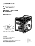
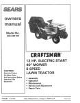
13.5 HP. ELECTRIC START
30" MOWER / MULCHER
5 SPEED
REAR ENGINE RIDER
•
•
•
°
F-99636
Assembly
Operation
Customer Responsibilities
ServiceAnd Adjustment
Sears, Roebuck and Co., Hoffman Estates, IL. 60179 U.S.A.
Printed
in US A
TABLE OF CONTENTS
WARRANTY .........................................
CUSTOMER RESPONSIBILITIES
2
......................
........
:;'i: ........
,i :i'ii ;i
t8
CHECK THE TIRES...,
•;'i..., .........
, ;. ; • ..........
HOW TO REMOVE AND INSTALL THE BLADE ...........
HOW TO SHARPEN THE BLADE ..........................
7
8
9
HOW TO ADJUST THE ATTACHMENT CLUTCH .............
HOW TO CHECK AND ADJUST THE DRIVE BRAKE .........
HOW TO CHECK AND ADJUST THE CLUTCH ..............
20
21
21
HOW TO REMOVE THE SIDE PANEL
BATTERY SERVICE
22
22
22
23
24
CHECK THE TIRES;_.;.,.:,.,:_..:.,I:..I.I:.;:.,..I:.,.....
CHECKTHEDR!VEBRAKE;,:._;,I::;_,..,I_;.,..
CHECK THE;:BELTS:I:;:, ;:i:.:.:; ..._:_ _ .._... !;..i;,,
19 : : :WHERE TO LUBRICATE
:.:..:...:.,.;
...............
; .....
9:
::: : HOW TO CHECK THE OIL i .....
.... _._ .......
.;:..,,i:,,
: 9
:: HOW TO CHANGE THE OIL ......................
.........
, ......
.. :.,...,
: "oWTo
CHARGE
TH; 'B' , 'F;;'IIIIIIIIIIIIIIIIIII'.IIIII
i::::_
26
..............
USE THE SHiFTLEVER
HOW
HOW
HOW
HOW
HOW
SET THE PARKING BRAKE :i"; _' ................
CHANGE THECUTTING HEIGHT .................
STOP THE UNIT. :i ..............................
TRANSPORT THE UNIT ..........................
OPERATE WITH THE MOWER HOUSING ..........
.i:::
'.:::iii!:
i_
:
12 ........ HOW TO REMOVE THE MOWER HOUSING
13
13
13
13
14
HOW TO OPERATE THE UNIT ON HILLS ...................
BEFORE STARTING THE ENGINE .........................
HOW TO START THE ENGINE .............................
14
15
15
HOW TO START WITH A WEAK BATTERY .................
HOW TO CHANGE THE MULCHER PLATE .................
15
16
OPERATING TIPS ........................................
MOWING AND BAGGING TIPS ............................
MULCHING TIPS
...... . .......
;:.,,;;
.......
;:,:
26
27
27
................
HOW TO INSTALL THE MOWER HOUSING .................
HOW TO LEVEL THE MOWER HOUSING ...................
HOW TO REPLACE THE MOTION DRIVE BELT .............
28
29
3O
31
31
31
31
32
HOW TO REPLACE THE MOWER DRIVE BELT .............
HOW TO REPLACE THE FUSE .:. .... ::il. :----. *...........
HOW TO SET THE CUTTING HEIGHT ......................
HOW TO CLEAN THE MOWER HOUSING .........
, ........
FRONT WHEEL ALIGNMENT ..............................
17
17
._, ::::17
STORAGE (OVER 30 DAYS) ...............................
TROUBLE SHOOTING
CHART ........................
33
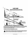
SLOPE
GUIDE
34
INDEX
..............................................
.......................................
35
36
:REPAIR:PARTS
LIMITED TWO YEAR wARRANTY
ON ELECTRIC
....
24
24
24
25
25
HOW TO CHECK THE SPARK PLUG .......................
!2 :::: SERVICE AND ADJUSTMENT
.........................
THE ATTACHMENT CLUTCH
HOWTO
TO
TO
TO
TO
TO
......................
_t0
: HOW T0 CLEAN THE COOLING SYSTEM...
............
10
HOW TO CHECK THE MUFFLER ..... . :.., : ...... _ ........
11, _ : HOW TO CLEAN THE AIR FILTERS . I:. ..........
i,i ........
:::LocATION oFcoNTROLs
__i :.i..; ._,,, !, ,:,,..:ii_ i !.._ ......
HOW TOUSE THE ;THROTTLE CONTROL:.
i. _!, ..
HOW ToUsE
i
18
19
19
,:,, ..
...
i
HOW TO INSTALL THE SEAT:;::.
: ::;.::_ ::.: ::. _.. _.. _... :.
CHECK THE LEVEL OF THE MOWER HOUSING .... ; .......
OPERATION;_I;_;;._!::_.:_:.IiI!!:;_I_....:_..;....:...;..
::
18
......................
MAINTENANCE FREE BATTERY ,_., ..i;i; ._
_;,__,:;_, ._ • •,
HOW TO ASSEMBLE THE STEERING WHEEL i, _. _., _....,..
HOW
TOASSEMBLE
THE
HUB
CAPS
:
RESPONSIBILITIES
MAINTENANCE CHART ; ............
3
3
4
5
6
RESPONSIBILITY OF THE OWNER .......
::: ........
:;::
ACCESSORIES AND ATTACHMENTS ;..: ;_:: !. i:i...:.. :.
: ASSEMBLY
CUSTOMER
i i.....
....:
START
....
RIDING
....
:
_
I!
H
EQUIPMENT
........ ....
H !
Fortwo(2)yearsfremthedateotpurchase,if thi_ri_ingequipmentis _a=_tained,
_ub_ioated
and tunedupaccordingtothe
I_:iil]
instructions
H
in the owner's
workmanshiP-i
This warranty
manuaI,
Sears will repair
i .... :
:
or replace,
: :
:
does not cover
free of charge
any parts found to be defective
: :
: ::
i
Tire replacement or repair caused by punctures from outside objects, such as nails, thorns, stumps or giass
Repairs necessary because of operator abuse, negligence,
improper :storage or acc dent orthe failure:to maintain
Riding equipment
to the instructions
used for commercial
contained
inthe owner's
spark plugs, air cleaners
manual,
:
or rental purposes.
'
::
LIMITED 90 DAY WARRANTY ON BATTERY
ti:it
:
:
according
normal use, such as blades,
or
::
:
Expendable
equipment
worn during
:
:
•
•
items which become
in material
li:!t
and belts.
[:]
H
I:::I
the
:
ti]
:
....
t:!:!I
:
liil]
I]
For 90 days from the date of purchase,
if any battery :included
workmanship
and our testing determines
the battery
WARRANTY
SERVICE
CENTER/DEPARTMENT
IS AVAILABLE
This warranty gives you specific
F-99636
..............................................
::
THE RIDING
i
Sears will replace
EQUIPMENT
:::
proves defective
:....
the battery
TO THE NEAREST
in material
and Coo, DI871WA,
......
2
Hoffman
_1
Ii t
SEARS SERVICE/_l!:il
:
Estates,
or
at no charge
H
legal rights, and you may also have other rights which may vary from state to state
Sears, Roebuck
.....
will not hold a charge,
BY RETURNING
IN THE UNITED STATES.
with this riding equipment
illinois
60179
..........................................................................
l_:ili!_t
H
i
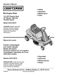
Congratulations on your purchase of a Sears Rider it has been
designed, engineered and manufactured to give you the best
possible dependability and performance
NOTE: This unit is equipped with an internal combustion engine and
must not be used on or near any unimproved forest-covered,
brush-covered or grass-covered land unless the engine's exhaust
system is equipped with a spark arrester meeting applicable local
or state laws (if any). If a spark arrester is used, it must be
maintained in effective working order by the operator.
If you experience any problems you cannot easily remedy, please
see your nearest Sears Service Department. We have competent,
well trained technicians and the proper tools to service or repair this
unit.
fn the State of California, the above is required by law (Section 4442
of the California Public Resources Code) Other states may have
similar laws. Federal laws apply on federal lands. See an Authorized
Service Center for a spark arrester for the muffler.
Please read and keep this manual. The instructions will enable you
to assemble and maintain your unit propedy Always observe the
"Safety Rules".
CUSTOMER
RESPONSIBILITIES
•
Carefully read and follow the rules for safe operation
the unit.
•
Follow all the assembly instructions. Carefully adjust the unit.
-
Know how tooperate all standard and accessary equipment on
the unit, Make sure the operator can correctly operate the unit.
operate the unit only with guards, shields and other safety
items in place and working correctly.
•
Inspect
•
Complete all maintenance on the unit. Service the unit only with
authorized or approved replacement parts
•
See the Maintenance Chart.
....
.........
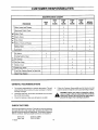
MAINTENANCE
AGREEMENT
A Sears Maintenance Agreement is available on this unit See the
nearest Sears Store for information.
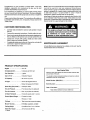
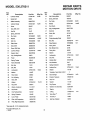
PRODUCT SPECIFICATIONS
Engine
......................
13.5 HP
Charging System .........
3 amperes at 3600 rpm
Fuel Tank Size ...........
1 gallon
Type of Fuel .............
Unleaded Regular
Oil Capacity
32 ounces (1 quart)
.........
Rear Engine Rider
Record in the space below the serial number and the date
of purchase of this unit.
The model number and serial number are found on a decal
attached to the rear of the frame.
Model Number: 536,270211
Oil Type .................
Above 32 degrees SAE 30
Serial Number:
Below 32 degrees SAE 5W30
Spark Plug (Gap 0.030") o, Champion RJ4C
Tire Air Pressure .........
Front 22 psi (See tire sidewall)
Tire Air Pressure .........
Rear 14 psi (See tire sidewall)
All Gear Transaxle ........
5 forward speeds and 1 reverse
Ground Speed Range .....
Forward 4 3 mph
..........
Tilt Seat.
Date of Purchase:
Keep these numbers for future reference
Reverse 2 1 mph
_...............
T_ltsforward to access the battery.
Mower Housing
..........
Full-floatingsuspension,oneblade
Cutting Height
......
8 positions from 14/2to 4 inches.
Blade Nut Torque .........
F-99636
30 foot-pounds (ft-lbs)
3
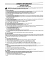
OWNER'S INFORMATION
SAFETY RULES
Safe Operation Practices for Ride-on Mowers
WARNING: This cutting machine is capable of amputating hands and feet and throwing objects. Failure to observe the
following safety instructions could result in serious injury :or death.
i.
•.,
"-eneral
oper-'*ion
=L
......
1. Read, understand andfollow all instructionsinthe instructionBook,on the machine, the engineandwith any attachmentsbefore starting
2. Only a! ow responsibleadults, who are familiar with the instructions,to operate the machine
3. Clear the area:of objects such as r0cksl toysi:wire_etc which could be picked up and thrown by the blade
4. Be sure the area is clear of other people before mowing Stop the machine if anyone enters the area.
5. Nevercarry passengers. :
:: ....
6. Turn offpower to the blades or any attachments before backing up. Do not mow in reverse unlessabsolutely necessary Always look
down and behind before and while backing.
7. Be aware ofthe mowerdischarge directionand do notpointitat anyone. Do notoperate the mowerwithouteither the entire grassbagger
or the mower guard in place_
:
:
8. Slow down before turning :
9. Never leave a machine unattended with the engine running.Always turn off the blade(s), set the parking brake, stop the engine and
remove the key before dismounting
10 Turn offpower to attachment(s) when transporting or not in use. Turn off the blade(s) when not mowing
11. Stop the engine before removing the grass bagger or uncloggingthe chute.
12 Mow only in daylight or good artificial light
t3. Do not operate the machine while underthe influence of alcohol or drugs or when very tired
14. Watch for trafficwhen operating near or crossingroadways.
' 15. Use extra caution when loadingor unloadingthe machine into a trailer or truck.
16. Always wear goggles, safety glasses, or an eye shield when you operate the unit to protect youreyes from foreign objects that can be
thrown from the unit. Always wear eye protectionwhen you make an adjustment or repair to the machine
17. Use care when pullingloads or using heavy equipment
a. Use only approved drawbar hitch points
b. Limit loads to those you can safely control
c. Do not turn sharply. Use care when backing.
d. Use counterweightsor wheel weights when suggested in the Instruction Book
18. Do not operate this machine if you are takingdrugs or other medication which can cause drowsiness or affect yourability to operate
this machine.
19 Do not use thismachine if you are mentally or physically unable to operate this machine safely
!1. Slope operation
Slopes and rough terrain are major factors related to loss-of-control and tip-over accidents, which can result in severe injury
or death. ALL slopes require extra caution. If you cannot back up the slope or if you feel uneasy on the slope, do not mow it. See
the "Slope Guide" in the back of this book to check for safe operation.
DO
1.
2.
3.
4.
5.
6
7.
Mow up and down slopes, not across.
Remove obstacles such as rocks, limbs, etc...
Watch for hoIes, ruts or bumps. Uneven terrain could overturn the machine. Tall grass can hide obstacles.
Follow the manufacturer's recommendations for wheel weights or counterweights to improve stability.
Use extra care with grass baggers or other attachments they can change the stability of the machine.
Keep all movement on the slopes slow and gradual. Do not make sudden changes in speed or direction.
Avoid starting or stopping on a slope. If tires lose traction, turn off the blades and proceed slowly straight down the slope
DO NOT
1.
2.
3
4.
5.
Do not turn on slopes unless absolutely necessary, then only turn slowly and gradually downhill, if possible
Do not mow drop-offs, ditches or embankments A wheel over the edge or an edge caving in could cause a sudden overturn and an
injury or death
Do not mow on wet grass Reduced traction could cause sliding
Do not try to stabilize the machine by putting your foot on the ground
Do not use a grass bagger or other rear mounted accessories on steep slopes (greater than 10 degrees)
I!i. Children
Tragic accidents can occur if the operator is not alert to the presence of children. Children are often attracted to the machine and
the mowing activity. NEVER assume that children will remain where you last saw them.
1. Keep children out of the mowing area and in the watchful care of another responsible adult
2
Be alert and turn the engine off if chi|dren enter the area
3. Before and when backing, took behind and down for small children.
F-99636
OWNER'S INFORMATION
4
5.
6.
Never carry children or any passengers, even with the blades off. They may fall off and be seriously injured or interfere with the safe
operation of the machine
Never alfow children to operate the machine. Instruct children in the potential dangers of the machine
Use extra care when approaching blind comers, shrubs, trees or other objects that may obscure vision.
IV. Service
1.
i
!
:
Use extra care when handlinggasotine and other fuels Fuets are flammable and the vapors are explosive
a Use only an approved container.
b Never remove the gas cap or add fuel with the engine running Atlow the engine to cool for several minutes before refueling Do
not smoke.
....
_ :
, : :
c. Never refuel the machine indoors,
d Never store the machine with fuel in the tank or fuel container inside where there is an open flame, such as a water heater.
2,
Never start or run the engine inside a closed area
3. Keep all nuts and bolts, especially the blade attachment nuts tight Frequently Check the blade(s) for wear or damage such as cracks
and nicks A blade that is bent or damaged must be immediately replaced with an original equipment blade from an authorized service
dealer. For safety, replace the blade every two years. Keep the equipment in good condition
4
Never tamper with the safety devices, Check their proper operation regularly.
5
To reduce fire hazards, keep the machine free of grass, leaves or other debris build-up Clean up oil or fuel spills Allow the machine
to cool before stodng.
6
Stop and inspect the equipment ff you strike an object Repair, if necessary, before restarting.
7
Never make adjustments or repairs with the engine running The carburetor can be adjusted with the engine running. Do not change
the engine governor settings or over-speed the engine.
8.
Grass bagger components are subject to wear, damage and deterioration, which could expose moving parts or allow objects to be
thrown Forstorage, always make sure the grass bag is empty. Frequently check components and replace with manufacturer's recommended parts when necessary
9.
Mower b ade(s) are sharp and can cut. Wrap the b ade(s) or wear g oves and use extra caution when servicing them or the blade housing
area.
10. Check the brake operation frequently. Adjust and service as required ........
11. Wa_ for all movement to stop before servicing any part of the unit.
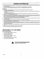
RESPONSIBILITY
Environmental
OF THE OWNER
Awareness
•
•
•
•
•
•
Do not fill the engine's fuel tank completely full.
Drain fuel for off-season storage .....
Use only unleaded gasoline.
:
Service the air cleaner regularly.
Change oil regularly Use 30W oil in summer.
Tune-up the engine regularly
•
Keep equipment in efficient operating condition.
Dispose of used engine oil properly
precautions.
symbol
indicates:
"Attention!
Look for this This
symbol
to indicate
important
safety
Become Alert! Your Safety Is At Risk,"
H
F-99636
5
ACCESSORIES
AND ATTACHMENTS
i
ACCESSORIES
AND ATTACHMENTS
These accessories and attachments were available when the unit was purchased. They are also available at most Sears retail outlets,
catalog and service centers Most Sears stores can order these items for you when you provide the mode_ number of your riding mower
ENGINE
SPARKPLUG
MUFFLER
AIR FILTER
ENGINE OIL
STABILIZER
PERFORMANCE
Sears offersa wide variety of attachments that fit your ridingmower. Many of these are listed below with brief explanations of how they can
help you. This list was current at the time of publication, however, it may change in future years- more attachments may be added, changes
may be mode in these attachments, or some may no longer be available or fit your modei Contact your nearest Sears store for the
accessories and attachments that are available for your unit.
Most of these attachments do not require additional hitches or conversion kits (those that do are indicated) and are designed for easy
attaching and detaching
GRASS BAGGER lets you collect grass clippingsand leaves for a
healthier, neater lookinglawn. Two Grass containers hold33 galfon
disposable plasticbags and offers7 bushel capacity.
CORING AERATOR takes small plugs out of soil to allow moisture
and nutrientsto reach grass roots 36-inch swath 24 hardened
2.5-inch steel coringtips. 150-|b we ght tray ......
LAWN SWEEPERS ]et you collect grass clippings and leaves
AERATOR promotesdeep root growth for a healthy lawn Tapered
2.5-inch steel spikes mounted on 10-_nch diameter disc puncture
holes in soil at close intervals to let moisture soak in Steel weight
tray for increased penetration
LAWN VACS for powerful collection of heavy grass clippings and
leaves. Wand attachment to pickup debris in hard-to-reach places.
CARTS make hauling easy Variety of sizes available.
MULCH RAKFJDETHATCHER loosens soil and flips thatch and
matted leaves to lawn surface for easy pickup Twenty spring tine
teeth Useful to prepare bare areas for seeding. Available for front
or rear mounting.
ROLLER for smoother lawn surface. 36-inch wide, 18-inch
diameter water-tight drum holds up to 390-|bs of weight Rounded
edges prevent harm to turf. Adjustab e scraper automatically cleans
drum
SPRAYERS use 12.Vott DC electric motor that connects to the
riding mower battery or other 12-volt source Includes booms for
automatic sprayLng when pulling, and hand held wand for spot
spraying Wand has adjustable spray pattern For applying
herbicides,insecticides,fungicidesand tiquid fertilizers
SPREADER/SEEDERS make seeding, fertilizing and weed killing
easy Broadcast spreaders are also useful for granular deicers and
sand
NOTE: Do not use pull-behind attachments on slopes that are greater than 10 degrees,
F-99636
6
ASSEMBLY
PREPARATION
5.
Phillips screwdriver
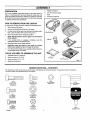
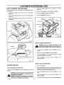
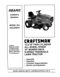
The unit is completely assembled except for the items shown in
Figure 1, These items are in the carton along with a parts bag The
parts bag contains the fasteners needed to complete the assembly
of the unit. Find and remove these items Do not discard any parts
or material until the unit is assembled
6
7
Low Tire pressure gauge
Knife
8
Socket Set (Optional)
HOW TO REMOVE FROM THE CARTON
To remove the un!t from the carton, follow the instructions below.
1
Open the top 0{ the carton
: ' :
2
Remove the wood frame at the top of the carton
3
Cut each corner of the carton from the top to the bottom with a
knife Lower the sides of the carton to the ground.
4.
SteeringWheel
--
Move the shift lever to the neutral (N) position.
NOTE: See the Operation section, page 11, for the location
of the controls.
5
If the parking brake is engaged, completely
clutch/brake pedal to release the brake
Move the lift lever to the highest position.
6,
push the
CAUTION: Check the bottom of the carton for staples,
Remove any staples that are in the path of the tires,
7.
Seat Bracket
From the back of the riding mower, carefully pull the riding mower backwards off the wood frame
TOOLS YOU NEED TO ASSEMBLE
1
Adjustable wrench (2 required)
2
3.
Open end wrench 1/2" -9/16"
Open end wrench 7/16"-'{/2"
4.
Blade type screwdriver
THE UNIT
Parts Bag
Owner's Manual
Figure 1
MOWER
PARTS
BAG - CONTENTS
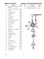
The fasteners and other loose parts are shown below The fasteners are shown at full size The quantity is shown in brackets ().
On some models, all of the fasteners are not required
%
2x_53
lx102
(I) Hex Bolt
5/16"-18x1_/2 "
STD523115
lx45
(2) Hex Bolt
_/le"-18x5i¢'
STD523106
I x38
(2) HexBolt
114"20x518°
STD523106
F-99636
"
(3) Carriage Bolt
STD533107
18x1_6
(2) Lockwasher
STD551131
54"148
(1) Cover, Battery
Terminal
15x88
(4) FlangeNut
51t6_-18
STD541431
Q
15x66
(2) Locknut
V4%-20
STD541425
91275
(2) Ignition Key
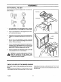
ASSEMBLY
MAINTENANCE
FREE
4
BA'I-rERY
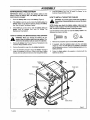
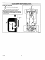
IMPORTANT: Before you attach the battery cables to the
battery, check the battery date. The battery date tells if the
battery must be charged.
1.
Check the battery date on top of the battery (Figure 2)
2.
If the battery is put into service before the battery date, the
battery cables can be attached without charging the battery
See "How To Install The Battery Cables".
3
HOW TO INSTALL
_
FREE BATTERY
Remove the battery. See "How To Remove The Battery" in the
Customer Responsibilities section.
2.
Remove
3.
Use a 12 volt battery charger to charge the battery Charge at
a rate of 6 amperes for one hour. If you do not have a battery
charger,
the protective
service center charge the battery.
, x°o
Remove the protective caps from the battery terminals
2.
If equipped, slide the terminal cover onto the red cable
(Figure 2) Fasten the red cable to the positive (+) terminal
with the fasteners as shown Push the terminal cover onto the
battery terminal
3.
Fasten the black cable to the negative (-) terminal with the
fasteners as shown.
caps from the battery terminals.
have an authonzed
the
positive To
(+)prevent
terminalsparks,
before fasten
you connect
black
WARNING:
the redthe
cable
to
cable.
IA!!!!!!!!!!
1,
1.
CABLES
Use the fasteners shown below to install the battery cables The
fasteners are shown at ful! size
smoke.
KeepWhen
the battery
away from
sparks.
WARNING:
you charge
the any
battery,
do The
not
fumes from the battery acid can cause an explosion.
,_
THE BATTERY
NOTE: Before you attach the battery cables, make sure the
battery is fully charged. This will extend the life of the battery
and provide the necessary power to start the engine.
If the battery is put into service after the battery date, the
battery must be charged. See "How To Charge The
Maintenance Free Battery",
HOW TO CHARGE THE MAINTENANCE
Install the battery See "How To Install The Battery* in the
Customer Responsibilities section ....
Positive (+)
Terminal
B
Battery [
Black Cable
Battery
Terminal
A
A
Red
CaNe
Z
i
Battery Clamp
Figure 2
F-99636
8
illll
ii,i
i
ASSEMBLY
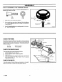
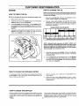
HOW TO ASSEMBLE
THE STEERING WHEEL
Use the fasteners shown below to instatlthe steering wheel, The
fasteners are shown at full size.
(B)
(A)
lx102
15x88
1
Make sure the front wheels point forward
2
Some models have an optional bellows, Slide the bellows
over the steering post. Make sure the collar of the bellows is
on top (Figure 3)
3
SteeringWheel
B
Bellows
(Optional)
Steering Post
Attach the steering wheel to the steering post with the fasteners Tighten the fasteners.
Figure 3
CHECK THE TIRES
Belt Guides_
MotionDrive Belt
Check the air pressure in the tires Tires with too much air pressure
will cause the unit to ride rough Also, the wrong air pressure will
keep the mower housing from cutting level. The correct air pressure
(PSD is as follows,
i ....
Front Tires
Rear Tires
CHECK
The
1
2
3.
4
:
THE DRIVE
Belt Guide
Mower DriveBelt
:22 PS1(1.5 BAR)
14 PSI (1 BAR)
Transaxte Pulley
Idler Pulley
BRAKE
drive brake Can be easily checked as follows.
Set the parking brake. See page 13.
Move the shift lever to the neutral (N) position
Push the unit
If the rear wheels rotate, adjust the drive brake See "How To
Check And Adjust The Drive Brake" in the Customer
Responsibilities section.
CHECK
THE
BELTS
Check the routing of the belts. Make sure the belts are not twisted
Make sure the belts are inside all the belt guides (Figure 4).
:
F-99636
9
i :¸
i
•
•
ASSEMBLY
i
HOW TO INSTALL THE SEAT
:
i
Use the fasteners shown belowto install the seat. The fasteners are
shown at full size:
:_
....
:
i
i
,i
Seat Hinge
D
'_lx45
::::
.....
2x53
....
;:
:i{B)
i::18x16
(D)
15x88
1
Set the seat bracket on the seat support (Figure 5) Pull the
wire harness between the seat hinge and the seat bracket.
2
Fasten the seat bracket to the seat support with the fasteners. Do nottighten the fasteners
.....
3.
Carefully remove the protective sleeve and the plastic bag from
the seat, Do not damage the wire attached to the bottom of the
seat.
....
Seat Bracket
Figure 5
Seat
Atign the holes in the seat hinge to the holes in the seat
(Figure 6). Fasten the seat to the seat hinge with the fasteners
as shown. Tighten the fasteners.
Check the operatingposition of the seat. :If:the seat needs to
be adjusted, slide the seat bracket forward or backward along
the seat adjusting holes as shown To keep the seat straight,
tighten the rear nut and then tighten the two front nuts
Fasten the connector to the wire harness. Make sure the tab
on the connector locks into the wire harness.
fasten the connector to the wire harness. If the
WARNING: For correct and safe operation of the unit,
connector is not attached, the engine will stop when
the attachment clutch is engaged.
Adjustin_°_les
"_
gure 6
CHECK THE LEVEL OF THE MOWER HOUSING
housing does not cut level, see the instructionson "How To Level
The Mower Housing" in the Service And Adjustment section of this
instruction book.
NOTE: After the unit is fully assembled, read the Operation
section.
The level of cut was set at the factory To check the level of cut, mow
a short distance and look at the area that was cut If the mower
F-99636
t0
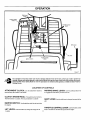
OPERATION
Clutch
Clutch / Brake
Pedaf
Throttle Control
Lever
Shift Lever
Lift Lever
Ignition
Ik
_
Switch
ParkingBrake
Lever
.
'
.....
[111
,m
I
Figure 7
The operation of any lawn mower can result in foreign objects thrown in the eyes, which can result in severe eye
damage. Always wear safety glasses or eye shields before starting your lawn mower and while mowing. We recommend the Wide Vision Safety Mask for over the spectacles or standard safety glasses, available at Sears Retail or
Catalog Stores.
LOCATION
OF CONTROLS
ATFACHMENT
CLUTCH:
Use the attachment clutch to
start and stop the rotation of the blade,
PARKING
BRAKE LEVER: Use the parking brake lever
to engage the brake when you leave the unit
CLUTCH / BRAKE PEDAL: The pedal has two functions
The first function is a clutch. The second function is a brake
SHIFT LEVER:
Use the shift lever to change the speed of the
unit.
IG NITION
SWITCH:
Use the ignitionswitch to start and stop
the engine
THROTTLE
LIFT LEVER:
F-99636
Use the lift lever to change the height of cut
CONTROL
LEVER:
Usethe throttle controt
lever to increase or decrease the speed of the engine
11
OPERATION
2
Move the attachment clutch to the ENGAGE position to rotate the blade(s),
3
The FAST position is marked with a detent. For normal operation and when using a grass bagger, move the throttle control
to the FAST position For maximum charging of the battery and
also for acooler running engine, operate the engine inthe FAST
position
Move the attachment clutch to the DISENGAGE position to
stop the blade(s) Before you leave the operator's position,
make sure the blade(s) has stopped rotating
4,.
Before you ride the unit across a sidewalk or a road, move the
attachment clutch to the DISENGAGE position.
2
For transport and to tow pull behind attachments, move the
throttle control to the SLOW position.
_
3
The engine governor isset at the factory for maximum performance Do not adjust the governor to increase the speed of the
engine
HOW TO USE THE THRO'I-rLE
CONTROL
Use the throttle control to increase or decrease the speed of the
engine
from
the blade,
deflector
opening,
WARNING:
Always
keep your
handsand
andthe
feetmower
away
housing when the engine runs.
>f
HOW TO USE THE A'I'rACHMENT CLUTCH
AttachmentClutch
_._
Note: If the engine stops when you engage the blade(s), the
seat switch is not activated. Make sure you sit in the middle of
the seat. Also, make sure the wire is connected to the seat
switch.
The attachment clutch isnext to the steering wheel (Figure 8). Use
the attachment clutch to engage the blade(s)
!.
Disengage_Position /_
Before you start the engine, make sure the attachment clutch
is in the DISENGAGE position
Figure 8
HOW TO USE THE SHIFT LEVER
To change the forward speed or the direction of the unit, fotlowthe
steps below
CAUTION: Before you move the shift lever, completely push
the clutchlbrake pedal forward to stop the unit. If the u nit is not
stopped, the gearbox can be damaged,
1.
Completely push the clutch/brake pedal forward to stop the
unit Keep your foot on the pedal
2.
Move the throttle control lever to the SLOW position
3
To move the shift lever to neutral (N) from a forward gear, pull
the shift lever back and then move to the right (Figure 9)
4.
To move the shift lever to a forward gear from neutral (N), pul!
the shift lever to the left and then push the shift lever forward.
5.
Slowly release the clutch/brake pedal. Do not keep your foot on
the pedal.
6
Move the throttle control to the FAST position
7
To move the shift lever to reverse,stop the unit Move the shift
lever back to reverse (R)
NOTE: Belt noise can occur when the clutch is engaged. This
noise is normal and does not affect the operation of the unit.
-
FUNCTION
SHIFTLEVER THROTTLE
5 Speeds
1
Trimming
Bagging Grass
1 or2
Mulching Grass
1 or2
Normal Mowing
2or3
Easy Mowing
3or4
FAST
i FAST
Shift Lever
II
Illll
m
m
SLOW
THROTTLE
SLOW - FAUST
Transpo_
C.OKEI lib
j
Pull Behind
Attachments
2or3
THROTTLE
Figure 9
i
F-99636
t
12
OPERATION
HOW TO SET THE PARKING BRAKE
1
2
3.
Completely push the clutch/brake pedal forward
Lift the parking brake lever (Figure !0)
Remove yourfoot from the clutch/brake pedal and then release
the parking brake lever Make sure the parking brake will hold
the unit
4
To release the parking brake, completely push the clutch!brake
pedal forward The parking brake will automatically release
WARNING: Before you leave the operator's
Parking Brake
Lever
Lift Lever
position,
parkingthebrake.
Move
attachment
ctutch Set
to the
move
shift lever
to the
the neutral
(N) position.
the
DISENGAGE position. Stop the engine and remove
the ignition key.
,_
HOW
TO CHANGE
THE
CUTTING
HEIGHT
To change the cutting height, raise or lower the lift lever as follows.
1
Move the lift lever forward to lower the mower housing and
back to raise the mower housing
2
When you ride on a sidewalk or road, move the lift lever to the
highest position and move the attachment clutch to the DISENGAGE position.
HOW
Figure 10
TO STOP THE UNIT
1.
Completely push the clutch/brake pedal forward to stop the
unit. Keep yourfoot on the pedal
2
Move the attachment clutch to the DISENGAGE position.
3
Move the shift lever to the NEUTRAL position
4.
Set the parking brake.
HOW TO TRANSPORT
,_
5.
Move the throttle control to the SLOW position
6.
To stop the engine, turntheignit]onkeytotheOFFposition
move the key.
Re-
THE UNIT
To transport the unit, follow the steps below
1. Move the attachment clutch to the DISENGAGE position
2
Raise the lift lever to the highest position
F-99636
WARNING:
Make sure the parking brake will hold the
unit.
!3
3.
Move the throttle control to a position between SLOW and
FAST.
4.
To go faster, move the shtft lever to a faster speed
OPERATION
HOWTO OPERATEWITH THE MOWERHOUSING
6
WARNING: The deflector is a safety device. Do not remove the deflector. The deflector forces the dis,_
NOTE: When you mow in heavy grass or mow with a
bagger, put the shift lever in the slowest speed.
charged
toward
the ground.
Always keep
the
deflector material
in the down
position.
If the deflector
is damaged, replace the deflector with an original equipment
part from an authorized service center.
t
Start the engine.
2.
Move the lift lever to a height of cut position In high or thick
grass, cut the grass in the highest position first and then lower
the mower housing to a lower position.
3
Move the throttle control to the SLOW position.
4.
Move the attachment clutch to the ENGAGE position.
5.
Push the clutch!brake pedal completely forward.
Move the shift lever to one of the speed settings
7,
Slowly release the clutch/brake pedal
8.
Move the throttle control to the FAST position. If you need to go
faster or slower, stop the unit and move the shift lever to another
speed setting.
9,
Make sure the level of cut is still correct. After you mow a short
distance, look at the area that was cut. If the mower housing
does not cut level, see the instructions on "How To Level The
Mower Housing" in the Service And Adjustment section.
,_
WARNING:
better control of the unit, always
select a safe For
speed.
3.
To start again, make sure the shift lever is in the slowest speed.
Move the throttle control to the SLOW position Slowly release
the pedal.
4.
If you must stop or start on a hill, always have enough space
for the unit to roll when you release the brake and engage the
clutch.
5.
Be very careful when you change directions on a hill When on
a slope or in a turn on a hill, move the throttle control to the
SLOW position to help prevent an accident.
HOW TO OPERATE THE UNIT ON HILLS
steep to back straight up. Never ride the unit across
WARNING:
Dothe
not "Slope
ride up Guide"
or downinslopes
that are
too
a slope. See
the back
of this
book for information on how to check slopes.
,_
1.
Before you dde up or down a hill, move the shift lever to the
slowest speed.
2
Do not stop or change speed settings on a hil!. If you must stop,
quickly push the clutch/b rake pedal forward and set the parking
brake
F-99636
14
OPERATION
BEFORE
STARTING
THE
ENGINE
CAUTION: A mixture of alcohol (ethanol or methanol) and
gasoline (called gasohol), will attract moisture and cause acid
deposits during storage. While the unit is in storage, the acids
in the fuel can damage the fuel system.
CHECK THE OIL
NOTE: The engine was shipped from the factory filled with SAE
30 weight oil. Check the level of the oil. Add oil as needed.
1 Make sure the unit is level
To prevent engine problems with the fuel system, empty the fuel
system before storage of 30 days or longer as follows.
NOTE: Do not check the level of the oil while the engine
runs.
2
3.
4.
Clean the area around the dipstick Remove the dipstick. Wipe
the oil from the dipstick
Insert the dipstick into the oil fill tube. Turn the dipstick clockwise until it is tight. Remove the dipstick. Check the oil level on
the dipstick. The oil level must reach the FULL mark on the
dipstick,
If necessary, add oil until the oil reaches the FULL mark on the
dipstick The quantity of oil needed from ADD to FULL is shown
on the dipstick. Do not add too much oil.
2.
Start the engine Let the engine run until the fuel lines and the
carburetor are empty.
3.
After storage, make sure you use fresh fuel. See the storage
instructionsfor additional information
4
Never use engine cleaner or carburetor cleaner in the fuel tank
or permanent damage can occur.
The factory settings for the carburetor are for most conditions. Ifthe
engine is operated under the following conditions, you can adjust
the carburetor mixture. See =How To Adjust The Carburetor _ in the
Service And Adjustment section
Do not smoke
add gasoline
when you
are inside
when adding
gasoline
to the an
fuelenclotank.
sure. Before you add gasoline, stop the engine and
let the engine cool for several minutes.
Fill the fuel tank with regular
unleaded gasoline.
Do not use
premium
unleaded
gasoline
Make sure the gasoline is fresh
and clean. Leaded gasoline will
increase
deposits
and shorten
the tife of the valves.
Drain the fuel tank
CARBURETOR
ADD GASOLINE
WARNING: Always use a safety gasoline container.
A
1.
1
The engine has a loss o| power or does not run smooth
Fuel Tank
A change from summer to winter operation.
-
A 40 degree change in the operation temperature The carbu reter was adjusted at 80 degrees at the factory.
3.
4.
The engine is operated above 4,000 feet.
III
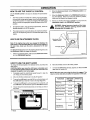
HOW TO START THE ENGINE
WARNING: The electrical system has an operator
presence system that includes a sensor switch
trical
system
if the
operator
sitting on the
This
mounted
in the
seat.
These is
components
tellseat.
the elecsystem will stop the engine when the operator leaves
the seat if the attachment clutch is engaged. For your
protection, always make sure this system operates
correctly.
1.
2
3
Move the shift lever to the neutral (N) position.
Make sure the attachment clutch is in the DISENGAGE position.
4
Move the throttle control completely forward to the CHOKE or
FAST position Somemodelshaveaseparatechokeknob
Pull
the choke knob to the full CHOKE position.
Turn the ignition key to the START position. Release the key
when the engine starts.
NOTE: If the engine does not start after four or five tries,
move the throttle control to the FAST position. Again try to
start the engine. If the engine will not start, see the
TROUBLE SHOOTING CHART.
Slowly move the throttle control to the SLOW position,
Let a cold engine run for several minutes. Begin workwhen the
engine is warm To start a hot engine, move the throttle control
to a position between FAST and SLOW.
5.
NOTE: The engine will not start unless you depress the
clutch/brake pedal, move the shift lever to the neutral (N)
position, and move the attachment clutch to the DISENGAGE
position.
6
7.
Sit in the middle of the seat Push the clutch/brake pedal completely forward Keep your foot on the pedal.
I
Jllll
1
I1[111[
[
HOW TO START WITH A WEAK BATTERY
NOTE: The unit is equipped with a 12 volt negative to ground
system. Also, the other vehicle must have a 12 volt negative to
ground system.
F-99636
IIII
I
J
I
III
I
II III
III
NOTE: If the seat is raised when starting the engine, move the
attachment clutch to the DISENGAGED position and engage
the parking brake.
If the battery is too weak to start the engine, the battery needs to be
charged. If =Jumper Cables" are used to start the engine in an
emergency, follow the procedure below.
A
I IIIIII I
1
2
Put a wet cloth over the vent caps of each battery
Connect each end of the RED "Jumper Cable" to the positive
(+) terminals of each battery Make sure you do not touch the
chassis with the cables.
3
Connect one end of the BLACK"Jumper Cable" to the negative
(-) terminal of the charged battery
Connect the other end of the BLACK "Jumper Cable" to the
mower's engine block,
Start the engine that has the weak battery last Allow the engine
to run.
WARNING: Do not smeke. The fumes from the battery
4
from
any flames
or explosion,
sparks. To prevent
acid can
cause an
Keep thesparks,
batteryfasten
away
the red "Jumper cable" to the positive (+) terminal before connecting the black "Jumper cable".
5
6
15
To disconnect the"Jumper Cables", reverse the above steps
OPERATION
HOW
TO CHANGE
THE
MULCHER
PLATE
3.
Lift the mulcher plate away from the mower
(Figure I3)
housing
connect
theTo
wire
from the
sure disthe
WARNING:
prevent
the spark
engineplug.
fromMake
starting,
attachment clutch is in the DISENGAGE position.
,_
The mulcher plate lets you mulch the grass for a clean, fine cut. To
discharge the grass out the side or into a grass bagger, remove the
mulcher plate as follows
Deflector
How To Remove The Mulcher Plate
1.
Raise the deflector. Remove the two wingnuts B and two carriage bolts A (Figure 11)
\
\
\
Mutcher Plate
Mufchef
Plate
Figure 13
4.
2.
Slide the mulcher plate toward the front (Figure 12). Make
sure the tabs on the mufcher plate are not locked behind the
nuts.
IMPORTANT: There are several different types of grass. Some
types of grass are more difficult to cut. If you remove the
mulcher plate and the grass does not discharge correctly,
replace the blade with a standard blade. The part number of the
standard blade is 56212E701.
To remove, slide forward
To install, slide backward
\
Attach wingnuts B and carriage bolts A to the mulcher plate
for future use.
Nut
How To Install The Mulcher Plate
Mulcher Plate
Figure 12
F-99636
16
1
Remove wingnuts B and carriage bolts A from the mulcher
plate.
2.
Raise the deflector. Slidethe mulcher plate under the deflector (Figure 13).
3.
Push the mulcher plate to the rear. (Figure 12). Make sure the
two tabs on the mulcher plate are lockedaround the two nuts
for the deflector bracket
4.
Fasten the mulcher plate with two wingnuts A and two cardage bolts B (Figure 11).
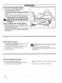
OPERATION
OPERATING
1.
TIPS
Check the attachment clutch for correct adjustment. For the
blade(s) to disengage correctly, the adjustment must be correct
5.
Before you make an inspection,adjustment (except for the carburetor) or repair, make sure the wire from the spark plug is disconnected.
6
Make sure the seat switch wire is connected. If the wire is not
connected, the engine will not start.
7.
For longer life of the battery, charge the battery every three
months
8
Use the shift lever to change the ground speed, notthe throttle
control.
9
Belt noise can occur when the blade or clutch isengaged This
noise is normal and does not affect the operation of the unit.
For a lawn to look better, check the cutting level of the mower
housing. See "How To Level The Mower Housing" in the Service And Adjustment section.
10.
For better engine performance
and an even discharge of the
cut grass, always operate the engine with the throttle in FAST
position.
2.
For the mower housing to cut level, make sure the tires have
the correct amount of air pressure (PSI)
11_ When you use a bagger, operate the engine with the throttle
FAST position and the shift lever in first or second gear
3,
Every time you use the unit, check the blade. If the blade is bent
or damaged, immediately replace the blade. Also, make sure
the nut for the blade is tight.
Before you use the unit, check the oil in the engine and add oil
if necessary
3.
If the engine will not start, first make sure the wire is attached
to the spark plug.
Make sure all the belts are inside all the belt guides See the instructions on how to remove and install the motion drive and
mower drive belts.
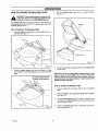
MOWING AND BAGGING TIPS
12.
4_
Keep the blade(s) sharpened.
of the grass to turn brown
5.
Do not cut or bag grass that is wet Wet grass wil not discharge
correctly Let the grass dry before cutting.
6.
Use the left side of the mower housing to trim near an object
7.
Discharge the cut grass onto the mowed area. The result is a
more even discharge of cut grass
8
When you mow large areas, start by turning to the right so that
the cut grass will discharge away from shrubs, fences, driveways, etc. After one or two rounds, mow in the opposite dkection making left turns until finished (Figure 14).
9.
If the grass is very high, cut two times to decrease the load on
the engine. First cut with the mower housing in the higbest position and then lower the mower housing for the second cut
13.
For better cutting performance
shift lever in one of the slower
and a quality cut, mow with the
speeds.
After each use, clean the bottom and top of the mower housing
for better performance.
prevent a fire
Wom blades will cause the ends
in
Also, a clean mower
housing
will help
.J
• IIIml
MULCHING
II
J
Figure 14
IIII
TIPS
When you use a mutcher attachment, the grass is cut into very small
pieces These small pieces will quickfy break down. Because the
nutrients are returned to the soil, the lawn will need less fertilizer Too
correctly mulch the grass, follow the steps below.
1.
2
4
Set the throttle in the FAST position Operate the mower at a
slower ground speed. If ground speed is too fast, the grass will
not have an even cut.
Set the height of the mower housing so that only the top third
of the grass is cut. If the grass is too high, set the height of the
mower housing to the maximum height Then, lower the mower
housing for the second cut Also, instead of using the full width
of the mower housing, mulch at half the w=dth
5.
Clean the bottom of the mower housing Grass and other debris
can keep the mower from working correctly
Keep a sharp edge on the blade A blade that is not sharp will
cause the ends of the grass to become brown
6.
If the grass grows fast, mulch more often.
7
If an area needs improvement, mulch a second time.
3. Make sure the grass is dry. Wet grass is difficult to cut
F-99636
17
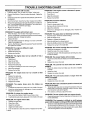
CUSTOMER
RESPONSIBILITIES
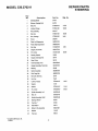
MAINTENANCE
II
PROCEDURE
EACH
USE
CHART
i ii
IIII
FIRST
2
HOURS
EVERY
25
HOURS
Blade, Inspect and Sharpen
4
Attachment Clutch, Check
4
M
Brake, Check
4
iO
Clutch, Check
4
W
EVERY
50
HOURS
EVERY
100
HOURS
,,
BEFORE
STORAGE
,
J
.......
E
Tire.s, Check
4
4
R
Battery, Check and Charge
4
4
Battery, Clean
!Lubrication
Oil, Check
4
Cooling System, Clean
4
4
4
,/
4
4
4
4
4
E
N
G
Oil, Change
Air Filter, Clean
4
I
Muffler, Check
4
N
Spark Piug, Check
4
E
...........
Fuel Filter, Replace (RemoteFuelTanksOnly)
4
Spark Plug, Replace
4
GENERAL
RECOMMENDATIONS
1.
The owner's responsibility is to maintain this product This will
extend the life of the product and is also necessary to maintain
warranty coverage.
2.
Check the spark plug, drive brake, lubricate the unit, and clean
the air filter once a year.
3
4.
WARNING: Before you make an inspection, adjust_
Check the fasteners Make sure al! fasteners are tight.
CHECK
THE TIRES
Check the air pressure in the tires Tires with too much air pressure
will cause the unit to ride rough. Also, the wrong air pressure will
keep the mower housing from cutting level. The correct air pressure
(PSI) is as follows Semi-pneumatic front tires do not require air.
Front Tires
RearTires
F-99636
22 PSt (1.5 BAR)
14 PSI (1 BAR)
Follow the Customer Responsibility and the Service And Adjustment section to keep the unit in good operating condition.
18
ment,
repair
to thethe
unit,wire
disconnect
wireplug
to the
spark or
plug.
Remove
from thethe
spark
to
prevent the engine from starting by accident.
CUSTOMER
RESPONSIBILITIES
INSPECT BLADE
9
Tighten the nut that holds the blade to a torque of 30 foot
pounds (41,5 N-m)
10 Install the mower housing See "How To Install The Mower
Housing".
WARNING= Before you inspect or remove the blade,
disconnect the wire to the spark plug. If the blade bits
an
stop has
the sharp
engine.
Check
the unit
damage.object,
The blade
edges.
When
you for
hold
the
blade, use gloves or cloth material to protect your
bands.
If you keep the blade sharp and inspect the blade for damage, the
blade wilf cut better and be more safe to operate Frequently check
the blade for excessive wear, cracks, or other damage. Frequently
check the nut that holds the blade. Keep the nut tight If the blade
hits an object, stop the engine. Disconnect the wire to the spark plug
See if the blade is bent or damaged Check the blade adapter for
damage. Before you operate the unit, replace damaged parts with
original equipment parts See the authorized service center in your
area_Every three years, have an authorized service person inspect
the blade or replace the old blade with an original equipment part
HOW
!
2
3.
TO REMOVE
AND
INSTALL
THE
Blade
A&_pt1
1
er_
Blade
I
BellevilleWasher
(Outsiderim must be
againstthe blade )
//
_/
Nut
Figure 16
I
BLADE
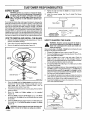
HOW TO SHARPEN
Remove the mower housing See the instructionson "How To
Remove The Mower Housing".
Use a piece of wood to keep the blade from rotating
Remove the nut that holds the blade (Figure 15).
THE BLADE
WARNING: Vibration can be caused if the blade is
,_not
correctly
if the
blade can
is damaged.
A
blade
that is balanced
damaged orwith
cracks
break and
cause an accident.
Keep a sharp edge on the blade A blade that is not sharp will cause
the tips of the grass to become brown.
1. Sharpen the blade two times a year or every 25 hours
2
Remove the blade according to the instructions in "How To Remove And Install The Blade".
Hi-Lift
Edge Up
3.
Mandrel
4.
5
Blade Adapter
Blade
6.
Figure
4.
5
6
15
7.
Check the blade and the blade adapter according to the instructions for "Inspect Blade". Replace a badly worn or damaged blade with an original equipment blade See an
authorized service center in your area
Clean thetop and bottom ofthe mower housing Remove atlthe
grass and debris
Mount the blade and blade adapter on the mandrel
(Figure t5)
7
Mount the blade so that the hi-lift edges are up. If the blade
is upside down, the blade will not cut correctly and can cause
an accident.
8
Fasten the blade with the original washers and nut. Make sure
the outside rim of the Belleville washer is against the blade
(Figure 16)
,_
F-99636
Clean the blade with a brush, soap and water Check the
blade. Look for cracks, nicks, or other damage. Replace a
badly worn or damaged blade with an original equipment blade.
See an authorized service center in your area.
Sharpen the blade with a file (Figure 17). Make sure you keep
the original bevel angle.
Make sure the blade is balanced Use a screwdriver and hold
the blade parallel to the ground (Figure 17). A blade that is
balanced will stay parallel to the ground. Ifthe blade is not balanced, the heavy end will rotate toward the ground Sharpen
the heavy end until the blade is balanced.
A new blade will cut better than a badly worn blade. Every three
years, have an authorized service person inspect the blade or
replace the old blade with an original equipment blade
Assemble the blade according to the instructions"How To Remove And Install The Blade"
Blade
Screwddv__
I
WARNING=
Always
thecan
nutcause
tight that
holds the
blade. A loose
nut orkeep
blade
an accident.
19
Bladeis balanced
I
when parallelto the ground I
Ground
[
"/
Figure17
CUSTOMER
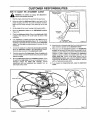
HOW TO ADJUST THE ATI'ACHMENT
,_
RESPONSIBILITIES
CLUTCH
AttachmentClutch
EngagePostion
1
Stop the engine. Disconnect the wire from the spark plug
2.
Before you adjust the attachment clutch, check and level the
mower housing. See "How To Level The Mower Housing"
Make sure the mower housing is level before go to the next
step.
3.
Set the height of the mower housing in the lowest position.
4.
Move the attachment
(Figure 18).
5.
Check the attachment clutch. Before the attachment clutch
engages, there must be 1/8" to 3/8" (3ram to 9mm) of free
movement.
6
If an adjustment is needed, disconnect the clevis from the
pivot rod and bracket assembly (Figure 19). Turn the clevis
clockwise to decrease the free movement of the attachment
clutch. Turn the clevis counterclockwise to increase the free
movement.
7.
"x,,.._
WARNING:
prevent
an injury, the attachment
clutch must To
operate
correctly.
%
clutch to the DISENGAGE position
Free Movement
1/8"-3/8" (3mm- 9ram)
Connect the clevis to the pivot rod and bracket assembly
Move the attachment
clutch to the DISENGAGE
position
Check the free movement of the attachment
clutch
Move the attachment clutch to the ENGAGE position. Check
the pad for the blade brake If the pad is excessively worn or
damaged, replace the brake pad assembly. Correct
replacement parts and assistance are available from an
authorized service center
Figure 18
10.
Attach the wire to the spark plug. Mow for a short distance and
again check the operation of the attachment clutch
11.
When you move the attachment clutch to the DISENGAGE
position, all movement will stop within five seconds if the adjustmentis correct If there is movement of the bett orthe blade
continue to rotate, engage and disengage the attachment
clutch five times to remove any excess rubber from a new
mower drive belt. If there is still blade rotation from the
DISENGAGED position, again adjust the attachment clutch
beginning with the first step tf you need assistance, take the
unitto an authorized service center.
12.
if you replace the mower drive belt, adjust the attachment
clutch.
Check the operation of the blade brake Rotate the pulley with
your hand Make sure that the blade brake pad presses tightly
against the pulley
9.
p'.
Blade Brake
Clevis Pin
Mower DrLve Belt
PivotRodand
BracketAssembly
Cotter P_n
Figure 19
F-99636
20
CUSTOMER
RESPONSIBILITIES
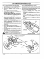
HOW TO CHECK AND ADJUST THE DRIVE BRAKE
HOWTO CHECKAND ADJUSTTHE CLUTCH
I.
If the motion drive belt is loose, the clutch will slip when, (1) going
up a hill, (2) pulling a heavy load, or (3) the unit wilt not move forward
Check the clearance at the rear of the pedal lever (Figure 21) If the
motion drive belt is loose, the clearance wilt be less than 1/2 inch
and the clutch will slip. Adjust the clutch as follows
I.
Disconnect the adjustable
nut from the idler bracket
(Figure 21).
2. Turn the adjustable nut clockwise to increase the fength of
the clutch rod. This adjustment will increase the clearance at
the pedal.
3
Connect the adjustable nut to the idler bracket with the
washer and cotter pin Check the clearance at the pedal
There must be 1/2 to 5/8 inch clearance at the back of the
pedal
4. After making an adjustmentto the pedal, check the brake rod
as described inthe instructions,"How To Check And Adjust The
Drive Brake".
2.
3.
4
5.
6.
7.
8
9.
Before you adjust the brake, check the clutch adjustment See
the instructions on "How To Check And Adjust The Clutch"
Make sure the shift lever is in the neutral (N) position.
Disconnect the adjustable
nut from the brake arm
(Figure 21),
Push the brake arm forward and hold in position.
With the brake arm forward, rotate the adjustable nut
counterclockwise on the brake rod until the adjustable nut
is in line with hole in the brake arm.
NOTE: If the adjustable nut will not line up with the hole in
the brake arm, go to step 6. If the adjustable nut does line
up with the hole in the brake arm, go to step 12.
Pull the brake arm to the rear of the unit.
The brake adjustment of the transaxle is located on the
underside of the transaxle (Figure 20) Use one wrench to hold
the brake stud and another wrench to hold the hex nut.
Loosen the hex nut approximately2 turns.
Turn the brake stud clockwise 1/2 turn. Try to push the unit. if
the unit roils, again turn the brake stud clockwise 1/2 turn.
Continue this adjustment until you feel resistance from the
brake when you push the unit.
Turn the brake stud countemtockwiseoneturn. Then, holdthe
brake stud with one wrench while you tightenthe hex nut with
another wrench
t 2. Connect the adjustable nut to the brake arm with the washer
and cotter pin.
13 Apply the parking brake Try to push the unit If the rear wheels
do notturn, the brake iscorrectlyadjusted. Release the parking
brake. Push the unit to see if the wheels will freely roll
,_
4%1
_
10 Push the brake arm forward and hotd in position.
11. With the brake arm forward, rotate the adjustable nut
clockwise until the adjustable nut is in line with the hole in the
brake arm
t,,,-_
Transaxle
Brake Stud
(TurnClockwise)
"%
WARNING:
If you
correctly adjust
drive
brake, take the
unitcannot
to an Authorized
ServicetheCenter.
i
VIEW FROM UNDERSIDE
Figure20J
Adjustable Nut (To increase the operation
the brake, turn counterc[ockwise )
Brake Arm
Cotter Pin
Nut
clearance,turn clockwise
)
]"_
Washer
Brake Rod
1/2" to 5/8"
(13ram to 16ram)
Cleat
Pedal
idler Bracket
\
/
Cotter Pin
CtutchRod
Figure 21
F-99636
1
21
CUSTOMER
RESPONSIBILITIES
HOW TO REMOVE THE SIDE PANEL
1.
To help service the engine or the battery, each side panel can be
easily removed.
Remove the black cable from the negative (-)
(Figure 24)
2.
Remove the red cable from the positive (+) terminal.
3.
Remove the battery clamp from the battery.
4
Remove the battery from the unit.
1.
Remove the screws that hold the back of the side panel
(Figure 22)
2.
Remove the large screws that hold the front of the side panel
(Figure 23).
3
Slideet;aenSjlde
panel back approximately oneinch Remove the
Positive (+)
Terminal
Date Code
terminal
_-...__.
Nut
BlackCable
/
Terminal Cover
Bolt
Battery Clamp
Figure 24
HOW TO CHARGE THE BATTERY
Side Panel
,_
Screws
/
smoke.
KeepWhen
the battery
away from
sparks.
WARNING:
you charge
the any
battery,
do The
not
fumes from the battery acid can cause an explosion.
1.
For longer life of the battery, charge the battery every three
months
2.
Before you charge the battery, remove the battery.
3.
To charge the battery, use a 12 voltbattery charger Charge at
a rate of 3 amperes for 2 to 3 hours.
4
Install the battery. See "How To Install The Battery _ in the
Assembly section,
Figure 23
HOW TO CLEAN THE BATTERY
BATTERY SERVICE
HOW TO REMOVE
THE BATTERY
1.
Remove the battery
2.
Wash the battery with a solution of one gallon of water and four
tablespoons of baking soda (sodium bicarbonate). Make sure
the solution does not get into the battery cells.
3.
Clean the terminals
brush.
4
install the battery
Assembly section.
5
To prevent corros=on, apply grease to the battery terminals.
To charge or clean the battery, remove the battery from the unit as
follows.
WARNING: To prevent sparks, disconnect the black
battery cable from the negative (-) terminal before you
,_
F-99636
disconnect The
the battery
red cable.
WARNING:
contains sulfuric acid which is
harmful to the skin, eyes and clothing. If the acid gets
on the body or clothing, wash with water.
22
and the ends of the cables with a wire
See "How To Insta]t The Battery" in the
CUSTOMER
RESPONSIBILITIES
WHERE TO LUBRICATE
Lubricate the areas shown with engine oil.
-'_
Apply grease with a brush to the areas shown.
NOTE: Apply grease to the steering gear assembly,
CAUTION: If the unit is operated in dry areas that have sand,
use a dry graphite spray to lubricate the unit, Do not lubricate
the nylon bearings for the front wheels. Oil or grease will
damage the bearings.
II
Shift Lever
/
Figure 25
F-99636
23
CUSTOMER
RESPONSIBILITIES
ENGINE
HOW
HOW
TO CHECK
THE
OIL
NOTE: Do not drain the oil from a cold engine. Before you drain
the oil, let the engine run for several minutes. Make sure you do
not get oil on the belts.
THE OIL
NOTE: Do not check the level of the oil while the engine runs.
1.
Make sure the unit is level.
2.
Clean the area around the dipstick (Figure 26). Remove the
dipstick. Wipe the oil from the dipstick.
3.
Insert the dipstick into the oilfi![ tube. Turn the dipstick clockwise until it istight. Remove the dipstick. Check the oil level on
the dipstick. The oil level must reach the FULL mark on the
dipstick.
4.
TO CHANGE
1.
Remove the oil drain cap. Drain the oil completely from the
engine. Instalt and tighten the oil drain cap
2.
Only use a high quality detergent oil rated with API service
classification
SG Select the oil's SAE viscosity grade
according to the expected operating temperature using the
temperature chart below:
Required
If necessary, add oil until the oil reaches the FULL mark on the
dipstick The quantity of oil needed from ADD to FULL is
shown on the dipstick Do not add too much oil.
Air Screen
SAE viscosity
<
•
grades
+
c, 3o
2_
TEMPERATURE
1'o
RANGE
.....
•
o
ANTICIPATED
1_
BEFORE
_;0
NEXT
I
OIL
_
I
CHANGE
Dipstick
NOTE: Although multi-viscosity
oils (5W30, !0W30, etc.)
improve starting in cold weather, these multi-viscosity oils will
result in increased oil consumption when used above 320 F.
Check the engine oil level more frequently to avoid possible
engine damage from running low on oil.
Clean the area around the dipstick Remove the dipstick.
Slowly pour approximately 32 ounces (1 quart) of oil into the
oil extension tube.
4.
Oil Dram Cap_
HOW
TO CLEAN
Engine Shroud
Figure 26
THE COOLING
insertthe dipstick intothe oil extensiontube Turn the dipstick
in a clockwise direction until it is tight. Remove the dipstick
Check the oil level on the dipstick. The oil level must reach the
FULL mark on the dipstick,
SYSTEM
The engine is air cooled The air that cools the engine enters through
the air screen on top of the engine. Clean the engine every 100
hours or every year as follows
1.
Remove any grass, dzrtor debns from the air screen with a
cloth or brush
2.
laspect the edge of the engine shroud for grass or debris.
Remove any grass or debris visible at the bottom edge of the
engine shroud
HOW TO CHECK THE MUFFLER
Check the muffler every 56 hours. Make sure the muffler is correctly
mounted and is not Ioose If the muffler is wom or burnt, replace with
a new muffler A worn muffler is a fire hazard and can damage the
engine
24
F-99636
If you mount a spark arrester to the muffler, also check the spark
arrester when you check the muffler. If the spark arrester is worn or
damaged, replace it with a new spark arrester See your nearest
authorized service center for a spark attester
CUSTOMER
RESPONSIBILITIES
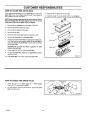
HOW TO CLEAN THE AIR FILTERS
Some engines have two filters, an outer foam filter around an inner
paper filter Clean the air filters every 50 hours tf you operate in
dirty conditions, service more often
11. Assemble the air filters with the two nuts
12. Install the cover Fasten the cover with the two wingnuts
NOTE: Never run the engine with the air filters removed. The air
filters witl help protect the engine against wear. For the correct
replacement filter, see the parts list for the engine.
Wingnut
1.
Remove the two wlngnuts from the cover (Figure 27)
2.
Remove the cover from the air cleaner
3.
Remove the two nuts from the filters.
4.
Remove the air filters.
5.
Clean the inside of the base and the cover with a cloth.
6.
Remove the foam filter from the paper filter.
7.
If equipped,wash the foam filter in a detergent and water solution. To remove the water solution, tightly roll the foam filter in
a dry cloth. Remove the foam filter from the cloth Completely
dry the foam filter
Cover
Nut
Foam Filter
Base
CAUTION: Do not wash the filters in gasoline or other
solvents that will burn.
8.
Evenly apply SAE 30W oil to the dry foam filter
9.
To clean the paper filter, lightly tap the paper filter against a
hard flat surface
Figure 27
10. If the paper filter is very dirty, replace the paper filter
]
I
HOW TO CHECK
]]
THE
SPARK
PLUG
1
Check the gap of the spark plug with a feeler gauge
(Figure 28). The correct gap is 0.030".
2.
For easy starting and good performance, replace the spark
plug every two years.
Feeler Gauge
0 030"
Spark Ptug
F-99636
25
Figure 28
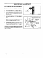
SERVICE AND ADJUSTMENT
HOW TO ADJUST THE THROTrLE
CONTROL
CHOKE
/
For the best engine performance, set the throttle control as follows
1
Move the throttle control to the FAST position (Figure 29).
2.
Loosen the clamp screw so that the throttle control cable
can move in the cable clamp (Figure 30) Do not remove the
cable clamp or disconnect the throttle control cable from the
engine control lever.
FAST
Throttle Control
3.
4.
SLOW
Figure 29
Move the engine control lever until the stot in the lever is
aligned (lines up) with the hole in the control bracket as
shown.
Engine Control Lever - FAST position
(Skitin leveralignedwithholein bracket)
Tighten the clamp screw. Move the throttle control to the
SLOW positionand then back to the FAST position.Check the
atignment of the throttle control lever See step 3.
Throttte Control
Cable
The throttle control is now set at the correct speed When the
throttle
control is at the FAST position, the engine speed is
3400 + or - 100 RPM. When the throttle
control is in the
SLOW position,
the engine speed is 2150 + or-
Cable Clamp
Clamp Screw
100 RPM.
IMPORTANT; Do not change the engine governor. If the engine
governor needs an adjustment, go to the nearest Authorized
Service Center. They have the equipment and experience to
make the adjustment.
F-99636
Control Bracket
Figure 30
26
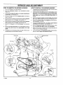
SERVICE AND ADJUSTMENT
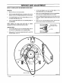
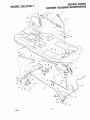
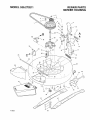
HOW TO REMOVE THE MOWER HOUSING
HOW TO INSTALL THE MOWER HOUSING
1.
2
Move the lift lever to the middle position
1.
Move the attachment
(Figure 31 )
Completely turn the steering wheelto the right. Push the mower
housing under the left side of the unit.
2
Slide the mower drive belt between the stack pulley and the
belt guide Put the mower drive belt around the stack pulley
Make sure the "V" side of the mower drive belt is against the
stack pulley. Also, make sure the mower drive belt is not
twisted.
clutch
to the DISENGAGE position
3.
Disconnect the blade drive link from the pivot rod and bracket assembly See illustration "C".
4.
Remove the hair pins from the adjuster plates
tions "A" and "B".
5
3.
Move the mower housing to the left until the right side adjuster
plate separates from the hanger. See illustration "A".
Attach the mower housing to the front hanger with the long
pin. Fasten with the washer and hair pin. See illustration "D"
4
6
Move the mower housing to the rightuntit the left side adjuster
plate separates from the hanger. See illustration "B".
Attach the adjuster plates to the hangers with the hair pins
See illustrations"A" and "B"
5
7.
Remove the long pin from the front hanger. See illustration
Connect the blade drive link to the pivot rod and bracket
assembly with the fasteners. See illustration "C'.
6.
Move the attachment clutch to the ENGAGE position Make
sure the mower drive belt is inside all the belt guides.
7.
Make sure the mower housing is level See the instructions on
"How To Level The Mower Housing".
8
Check the operation of the attachment clutch. See the instructions on "How To Adjust The Attachment Clutch".
lIg_
See illustra-
-
Remove the mower drive belt fromthe stack pulley. Slide the
mower drive belt between the stack pulley and the belt
guide
9.
Completely turn the steering wheel to the right. Pull the mower
housing away from the left side of the unit.
Stack Pulley
Attachment
Clutch
t
Blade
Drive
Link
Belt Guide
/
Long Pin
/"
Lift Lever
Hair Pin
D
Hanger
Mower DnveBelt
B
\
Adj
/__1
Hanger
Front Hanger
F-99636
27
c B'_lade DnveLink
SERVICE AND ADJUSTMENT
HOW TO LEVEL THE MOWER HOUSING
1.
If the mower housing is level, the blade wiltcut easier and the lawn
will look better.
2.
WARNING: Before you make an inspection, adjust_iL
ment,
repair
to the the
unit,spark
disconnect
the to
wire
to the
spark or
plug.
Remove
plug wire
prevent
the engine from starting by accident.
1.
Make sure the unit is on a hard level surface
2.
Check the air pressure in the tires. If the air pressure is mcorrect, the mower housing will not cut level Make sure the rear
tires are inflated to 14 psi. (1 BAR) and the front tires to 22 psi.
(1.5 BAR)
Move the lever for the attachment clutch to the ENGAGE position Move the lift lever to the middle position
There are two adjustment procedures below that will levet the
mower housing
3.
4.
3.
THE
4.
Disconnect one or both adjuster plates from the hangers
(Figure 33)
The higher number holes in the adjuster plates will raise the
height of the mower housing The lower number holes will lower
the mower housing
Connect the adjuster plates to the hangers in the holes that
will level the mower housing. Fasten the adjuster plates with
the hair pins
Check the housing for the correct adjustment If necessary, repeat the adjustment
\.
Hanger
SIDE TO SIDE ADJUSTMENT
There are measuring points on the mower housing indicated by
small round dimples A, B, C, and D shown in Figure 32. To
determine if an adjustment is needed, use a ruler and measure the
distance from the level surface to the bottom of the mower housing
at points C and D. in correct adjustment, the mower housing at
points C and D must be within 1/4" (6 mm) of the same height If the
difference in the measurement is more than 1/4" (6 mm), adjust as
follows.
Hair Pin
i///
AdjusterPlate
THE
J.m/
TO BACK
ADJUSTMENT
To determine if an adjustment is needed, use a ruler and measure
the distance from the level surface to the bottom of the mower
housing at points A and B. In correct adjustment, the front of the
mower housing at pointA wiltbe 1/8" to 3/8" (3mm to 9ram) lower
than the back of the mower housing at point B. Adjust as follows.
SIDE VIEW
,
bottom
of the mower housing
FRONT
Figure 33
1.
2.
_,
LEVELSURFACE
3
4.
5.
Loosen the jam nut (Figure 34).
Turn the Iocknut clockwise to raise the front of the mower
housing Turn the Iocknut counterclockwiseto lower the front
of the mower housing
Check the housing for the correct adjustment if necessary, repeat the adjustment
Tighten the jam nut
Connect the wire to the spark plug.
Suspens=on Bracket
Suspension Rod
C
D
Adjusting Clevis
Jam Nut
Counterclockwise
Locknut
Figure 32
F-99636
Figure 34
28
SERVICE AND ADJUSTMENT
HOW TO REPLACE THE MOTION DRIVE BELT
2
Slide the motion drive belt between the belt retainer and idler
pulley Make sure the ftat side of the motion drive belt is against
the idler pulley. Also, make sure the belt is not twisted
3
Install the motion drive belt around the drive pulley
4.
Make sure the motion drive belt is inside all the belt guides
Try to pull the motion drive belt off the drive pulley If the belt
guides are too close to the drive pulley, loosen the belt
guides (Figure 36)
5.
Make sure all the belt guides are tight
6
Before you use the unit, check the adjustment of the clutch See
the instructions "How To Check And Adjust The Clutch".
4.
5.
Remove the motion drive belt from the idler pulley
Pull the motion drive belt toward the front of the unit.
7
install the mower housing See the instructions"How To install
The Mower Housing"
6.
Remove the motion drive belt from the stack pulley. If
necessary, loosen the belt guide at the stack pulley. A correct
replacement part or assistance is available from an authorized
service center in your area
REMOVAL
1.
Remove the mower housing See the instructions on "How To
Remove The Mower Housing"
2.
Completely push the clutch/brake pedal forward and engage
the parking brake.
3.
INSTALLATION
1
Slide the motion drive belt between the stack pulley and the
belt guide, install the motion drive belt on the top pulley of the
stack pulley. Make sure the "V" side of the belt is against the
pulley (Figure 35).
j
Pulley
F_gure 35
Stack Pulley
Loosen
Belt Guide
BeltRetainel
Belt Guide
Drive PuIley
O
Figure 36
F-99636
29
SERVICE
HOW
TO REPLACE
THE
MOWER
AND ADJUSTMENT
DRIVE
BELT
REMOVAL
1
Move the lift lever to the lowest position.
2
Slide the mower drive belt between the stack pulley and the
belt guide. Remove the mower drive belt from the stack pulley
3.
Pull the belt retainer away from the idler pulley and remove
the mower drive belt (Figure 38).
4.
Slide the mower drive belt between the mandrel pulley and
the belt guides
3
Pull the belt retainer away from the idler pulley. Put the
mower drive belt around the idler pulley
4.
Make sure the mower drive belt is inside all the belt guides
Also make sure the mower drive belt is not twisted.
5
Slide the mower drive belt between the stack pulley and the
belt guide. Install the mower drive belt around the the stack
pulley
6
Before you mow, check the attachment clutch See the instructions on =How To Adjust The Attachment Clutch".
NOTE: Replace the mower drive belt with an original
equipment belt from an authorized service center.
INSTALLATION
1.
Pull the belt guides away from the mandrel pulley Slide the
belt between the belt guides and the mandrel pulley.
2,
Make sure the =V" s=deof the mower drive belt is against the
mandrel pulley (Figure 37).
_
Pulley
Figure37
@
Belt Retainer
Idler Pulley
Mower Ddve Belt
Figure 38
F-99636
30
SERVICE AND ADJUSTMENT
HOW TO REPLACE THE FUSE
If the fuse is blown, the engine will not start The location of the fuse
is next to the battery Remove the fuse and replace with a 15 amp
automotive fuse (Figure 39)
15 amp
_
AutomoUveFuse
Figure39
HOW TO SET THE CUTTING HEIGHT
The cutting height is set at the factory from tl/2 to 4 inches. To lower
or raise the cutting height, make an adjustment to the lifter rod as
follows.
1_
Move the lift lever to the lowest position
2.
Disconnect the lifter rod from the lifter arm (Figure 40).
3.
Turn the lifter rod clockwise to lower or counterclockwise to
raise the cutting height
4.
Attach the lifter rod to the lifter arm.
5.
Move the lift leverto the highest position. Make sure the pulleys
or belt do not touch the bottom of the frame
Hair Pin
""----
\
Ufter Rod
Wash
Figure 40
HOW TO CLEAN THE MOWER HOUSING
,_
stop
the engine
and you
disconnect
the mower
wire to the
spark
WARNING:
Before
clean the
housing,
plug.
Grass and other debris on top of the mower housing can keep the
belt from working correctly For safety and correct operation,
frequently clean the top of the mower housing Remove grass and
debris from around the pulleys and other moving parts
2.
Clean the top of the mower housing.
3.
Move the lever for the attachment clutch to the DISENGAGE
position.
4.
Again clean the top of the mower housing
5.
After you cut the grass, clean the bottom of the mower housing.
FRONT
WHEEL
ALIGNMENT
The alignment of the front wheels cannot be adjusted Ifthe steering
is damaged and the alignment has changed, see your nearest
Move the lever for the attachment clutch to the ENGAGE posiauthorized service center
tion.
F-99636
31
1.
SERVICE AND ADJUSTMENT
prevent engine problems with the fuel system, empty the fuel
system before storage of 30 days or longer.
STORAGE (over 30 days)
At the end of each year, prepare the unit for storage as follows
NOTE: Fuel stabilizer (like STA-BtL)
is an acceptable
alternative in reducing the formaUon of fuel gum in the fuel tank
and the gasoline storage container. Always follow the mix ratio
located on the container of stabilizer. Ru n the engine at least 10
minutes after adding the stabilizer to allow the stabilizer to
reach the carburetor. Do not drain the fuel tank and carburetor
if stabilizer is used.
GENERALINSPECTION
1.
Inspect the belts. If the belts are damaged or worn, replace with
replacement belts from the factory See the belt replacement
instructions in the Service And Adjustment section.
2
Make sure all nuts, bolts and screws are tight, inspect moving
parts for damage, breakage and wear Replace if necessary.
MOWER
1.
If you do not use a stabilizer, do the following:
HOUSING
Clean the mower housing See "How To Clean The Mower
Housing".
LUBRICATE
1.
Startthe engine.
2.
Run the engine until the fuel tank and the carburetor are out of
fuei and the engine stops.
3
Do not leave fueiin the fueltankor the carburetor The fueican
damage the function of the fuel system. Some models have a
fuel drain (Figure 41) Hold a ctoth under the fuel drain Push
the fuel drain until the carburetor is empty.
4.
After storage, make sure you use fresh fuel.
THE UNIT
See the =Where To Lubricate"
Responsibilities section.
instructions in the Customer
THE ENGINE
1.
Clean the dirt and grass from the engine.
2.
Change the oil. See the instructions, "How To Change The Oil".
3.
Check the air screen. See the instructions, "How To Clean The
Cooling System".
4
Check the spark plug. See the instructions, "How To Check The
Spark Plug".
/
Fuel Drain
Figure 41
THE FUELSYSTEM
THE BATTERY
,_
ing
or near aDo
fire.
not the
smoke
because
thea fumes
WARNING:
notDo
drain
gasoline
inside
buildfrom the fuel can cause an explosion.
CAUTION: During storage, it is important to prevent deposits
from occurring in fuel system parts like the carburetor, fuel
filter, fuel line and the fuel tank. Alcohol gasoline mixtures
(called gasohol or using ethanol or methanol) attract moisture
causing acid deposits during storage. While the unit is in
storage, the acids in the fuel can damage the fuel system. To
F-99636
1
Remove the battery
2
Clean the battery terminals of any deposits
3.
Charge the battery. See the instructions on "How To Check And
Charge The Battery".
4.
Store the battery in a cool, dry place
NOTE: After a tong time in storage, charge the battery.
32
TROUBLE
SHOOTING
CHART
PROBLEM: The engine will not start.
1
Follow the steps, =HowTo Start The Engine" in this book
PROBLEM: A hot engine causes a decrease
1. Clean the air screen
2
Electric-Start Models Clean the battery terminals 33ghten the
cables
2
Check the oil
3
Check for a loose wire Tighten the limit switches. (See the wiring diagram.)
Drain the fuel tank Clean the fuel fine Replace the fuel filter.
Remove the spark plug(s). Move the throttle to the SLOW position. Turn the ignition key to the ON position.Try to start the engine several times install the spark plug
Replace the spark plug
Adjust the carburetor
3
4
Adjust the carburetor
Replace the fuel filter
4
5.
6.
7.
PROBLEM: The engine will not turn over.
t.
Follow the steps, "Hew To Start The Engine" in this book.
2
Electric-Start Models: Check the level of the acid in the battery
tf needed, add water. Charge the battery
3. Replace the fuse.
4
Check the wiring harness for damage or a loose connection
Repair the damaged wire
5. Electric-Start Models replace the solenoid. Recoil-Start Models: replace the module.
PROBLEM: The engine is difficult
1
Adjust the carburetor
2
Replace the spark plug
3
Replace the fuel filter
PROBLEM: The engine
loss of power.
1
Check the oil.
2. Clean the air filter.
3
Clean the air screen.
4
5.
6
7.
4.
or has a
Replace the spark plug
The engine is working too hard. Use a lower gear
Adjust the carburetor
Replace the fuel filter
PROBLEM:
The engine does
speed.
1
Replace the spark piug
2
Adjust the throttle control
3. Clean the air filter.
not run smooth
PROBLEM: Excessive vibration,
1. Replace the blade
2
Check for loose engine botts.
3
Decrease the air pressure in the tires
4.
5.
Adjust the carburetor
Check for a damaged belt or damaged pulley Replace the
damaged parts.
PROBLEM: The grass does not discharge correctly.
t.
2.
3.
4.
5.
Stop the engine Clean the mower housing
Raise the height of cut.
Replace or sharpen the blade(s).
Move the shift lever to a slower speed.
Move the throttle control to the FAST position.
6.
Replace the spring for the blade idler.
PROBLEM: The mower housing does not cut level.
t. Check the air pressure in the tires
2. Adjust the level of the mower housing
3. Check the front axle If the frontaxle does not freelypivot, loosen the axle bolt(s).
to start.
does not run smooth
in power,
at fast
Replace the fuel filter
PROBLEM:
The engine stops when the blades
are
engaged.
I.
Toactivate the seat sensor, always sit inthe middle of the seat
2
Check the wiring harness for damage or a loose connection.
Repair the damaged wire.
PROBLEM: On slopes, the engine stops.
1. Mow up and down slopes Never mow across a slope
2
To activate the seat sensor, always sit in the middle of the seat
PROBLEM: The engine will not idle.
1
Replace the spark plug.
2
Clean the air filter
3
Adjust the carburetor
4
Adjust the throttle control
5
Drain the fuel tank Clean the fuel line Replace the fuel filter
33
F-99636
PROBLEM: The mower blades will not rotate.
1. Check the mower drive belt Make sure the belt is installedcorrectTy.
2, Replace the mower drive belt
PROBLEM: The unit will not move when the clutch is
engaged.
1. Check the motion drive belt Make sure the belt is installed
correctly.
2. Adjust the clutch
3. Replace the motion drive belt
PROBLEM: The unit moves slower
clutch is engaged.
1. Adjust the clutch
2. Replace the motion drive belt.
or stops when the
PROBLEM: When the clutch/brake pedal is released, belt
noise can be heard.
1. Temporarybelt noisedoes notchangethe operation ofthe unit.
tt belt noise is continuous, check the routing of the belt Make
sure the belt is inside all belt guides.
2
If the noise is continuous, adjust the clutch.
PROBLEM: The rear wheels spin over uneven terrain.
1. Check the front axle. If the front axle does not freely pivot, loosen the axle bolt(s).
PROBLEM: The transaxle is difficult to shift between
gears with the engine running and the clutch depressed.
1. Check the clutch adjustment to make sure the belt stops when
the clutch pedal is depressed with the transaxle in (N) neutral
2
Check the belt guides around the transaxle drive pulley Make
sure the belt guides do not touch the pulley
QD
1
Operate a walk-behind mower
across the face of slopes,
never up or down slopes.
I
GO
4:=
[
L
10 DEGREES
15 DEGREES
Operate a riding mower
up or down slopes, never
across the face of slopes.
On a riding mower to determine if a slope is safe to mow: (1) disengage the blade(s), (2) put the unit in reverse, and (3) try to back straight up the
slope. If you can back up the slope, it is generally safe to mow. However, if you do not feel safe, or if you are not completely sure, use this guide
and do not mow a slope that is greater than 15 degrees. If the riding mower is used with a pull-behind
or rear mounted attachment,
do not operate the unit on a slope that is greater than 10 degrees.
A 15 degree slope is a hill that increases
A 10 degree slope is a hill that increases
in height at approximately
in height at approximately
2.5 feet in 10 feet.
1.7 feet in 10 feet.
slopes.
Operate
riding
mowerand
upavoid
or down
slopes,
never
across the face
of slopes.
Operate a walk-behind
acrossin mowing
the face on
Use
extreme
carea at
all times,
sudden
turns
or maneuvers.
Follow
other instructions
in this manualmower
for safety
of slopes, never up or down slopes. Use extra care when operating on or near slopes and obstructions.
.....................................
c'u__#_ _(; OS'E'SZ_P_
&_16E"....................................
INDEX
A
D
Adjustments
Attachment Clutch, 20
Clutch, 21
Drive Brake, 21
Mower Housing
Cutting Height, 31
Level, 28
Air Screen, 24
Attachment Clutch
Adjust, 20
Location, 11
Operation, 12
Attachments, 6
Drive Brake
Adjust, 21
Check, 21
E
Engine
Cooling System, 24
Fuel, 15
Lubrication, 24
Muffler, 24
Oil, 15, 24
Spark Arrester, 24
Starting, 15
Throttle Control, 12
B
F
Battery
P
Filter, Air, 25
Charge, 22
Check, 8
Check Acid Level, 22
Clean, 22
Emergency
Start, !5
Install, 8
Removal, 8, 22
Belt
Motion
Type, 15
Operation
Attachment Clutch, 11, 12
Clutch / Brake Pedal, 11
Emergency Start, 15
Ignition Switch, 11
Lift Lever, 11, 13
Location Of Controls, 11
Mower Housing, 14
Mowing And Bagging, 17
Mulching, 17
Operate On Hills, 14
Parking Brake, 11, 13
Shift Lever, tl, 12
Start The Engine, 15
Stop The Unit, 13
Throttle Control, 1t, 12
Transport, 13
Fuel, Type,
Ignition
Switch,
Parking Brake
Location, 11
Operation, 13
Location,
Adjust, 21
Replace, 29
Routing, 9
Mower Drive
Location, 11
Operation, 13
Lubrication
Engine, 24
Mower, 23
M
19
C
Clutch
Adjust, 21
Check, 21
Clutch / Brake Pedal, Location, 11
Customer Responsibilities
Attachment Clutch, 20
Battery
Charge, 22
Check Acid, 22
Clean, 22
Blade, 19
Clutch, 21
Drive Brake, 2t
Filter, Air, 25
Lubrication, 23
Maintenance Chart, 18
Muffler, 24
Spark Plug, 25
Cutting Height
Adjust, 28, 31
Change, 13
F-99636
S
Seat, Install, 10
Lift Lever
Adjust, 20
Replace, 30
Routing, 9
Blade
11
Safety Rules, American National
Standard Institute, 4-5
L
Drive
Inspect, 19
Remove And Install,
Sharpen, 19
15
Fuse, 31
Maintenance Chart, 18
Motion Drive Belt
Adjust, 21
Replace. 29
Mower Drive Belt
Adjust, 20
Replace, 30
Mower Housing
Clean, 31
Cutting Height, 13, 31
Install, 27
Level Adjustment, 28
Operation, 14
Remove, 27
Muffler, 24
Spark Arrester, 24
Mulcher
Install, 16
Operation, 17
Remove, 16
0
Service And Adjustment
Belt
Motion Ddve, 29
Mower Drive, 30
Fuse, 31
Mower Housing
Clean, 31
Cutting Height, 31
Instal[, 27
Level, 28
Remove, 27
Storage, 32
Shift Lever
Location, 11
Operation, 12
Side Panel, 22
Slope Guide, 34
Spark Attester, 24
Spark Plug, 25
Steering Wheel, 9
Storage, 32
T
Throttle Control
Location, 11
Operation, 12
Tire Pressure, 9, 18, 28
Trouble Shooting Chart, 33
W
Oil
Change, 24
Check, 15, 24
35
Wheel Alignment, 31
MODEL 536.270211
REPAIR PARTS
BODY CHASSIS
14
13
2O
26
8
22
36
17
10
28
\
64
22
27
21
_,
32
3O
21
22
34,
31
16 35_
5O
//
//
\
/
/
22
\
\
t
11
45
iX
/
41
58
65
62
63
F-99636
REPAIR PARTS
BODY CHASSIS
MODEL 536.270211
Key
No.
Description
Part No.
Key
No.
Mfg. No.
Description
Part No.
1
Seat
92387
36
Screw
26x250
2
Hinge,Seat
56516E700
37
Support,Body
56122E700
3
Retainer
28x64
38
Belt,Shoulder
9x29
4
Lockwasher
STD551131
39
Lockwasher
STD551231
40
Screw
26x49
18x16
lx45
5
Bert, Hex
STD523t06
6
Plate,Seat Switch
91963Z
41
Locknut,Range
STD541437
7
Spring,Compression
164x26
42
ClampAssembly,Battery
54800Z
8
G[ide,Seat Spring
91822
43
Washer
STD551025
9
Bolt, Shoulder
9x38
44
Support,SteeringColumn
56240E700
10
Spring, Seat
91964
45
Mat,Left
54795
11
Locknut,Flange
STD541431
46
Mat,Right
54796
12
Bracket, Seat Pivot
56518E700
47
Frame
56612E549
13
Cap, Push On
28x23
48
Screw
6x74
14
Rod, Seat Hinge
56537Z
49
Locknut
STD54t425
!5
Support,Seat
56519E700
50
16
Screw
26x249
Engine,Craftsman
Model143.981300
Bolt, Carriage
STD533107
51
Bolt,EngineMount
25x7
17
18
Panel, Right Side
54764E549
56
Cap,Fuel
92317
19
Panel, Left Side
54763E549
57
Tank,Fuel
55805
Cover,SteeringColumn
94353
58
Screw,Hex
26x213
20
Bracket, Panel
54747E549
59
Clamp,Hose
23717
2t
Screw,Tapping
26x270
60
Line,Fuel
91022
22
23
Panel,Control
94351
61
Bracket,RemoteTank(Front) 94940
24
Screw
STD610803
62
Clamp,GasLine
91174
25
Throttle Control
56247
63
Filter,Fuel
56002
26
Console
56405E549
64
Panel,Rear
54782E549
27
Cap, Front Console
56407E549
65
Bracket,RemoteTank(Rear) 94941
Cover, Lower Console
94352
-
Owner'sManual(English)
F-99636
28
29
Retainer
28x52
-
Owner'sManual(Spanish)
F-99636 SP
30
J-Nut
28x18
-
Decal RightPanel
44x7970
Panel,Front
56235E549
Decal LeftPanel
44x7969
3I
32
Screw,Southco
91330
DecalShift
44x4741
Panel, LeftAccess
56406E549
Decal FrontConsole
44x7973
33
Bearing, SteeringPost
56022
Decal Clutch/Brake
44x1627
34
35
Bracket,Cover Mounting
56233E700
15x88
2x53
26x201
Decal FrontConsoleWarning 44x7325
* NOTE:Seepages50 - 55for replacement
parts.
F-99636
37
Mfg. No.
19x6
15x84
17x38Z
15x66
7
\
_4
_..
_ro
\
_6
\
/
->
I
/AO
,
\
29
't59
5
%
e
'tO
_4
>_77_
_@9635
• it-"
REPAIR PARTS
MOTION DRIVE
MODEL 536.270211
Key
No.
Description
Part No.
1
Locknut,
Flange
STD541431
3
Guide,Belt
4
Mfg. No.
15x88
Key
No.
Description
Part No.
Mfg. No.
40
Unk,Parking Brake
56565Z
93349
41
Spring, Extension
165x107
Shifter
Assembly
56610E700
42
Pin,Cotter
STD560907
30x50
5
Locknut,
Flange
STD541437
43
Washer
STD551031
17x46Z
6
Screw
26x267
44
Rod, Clutch
5653tZ
7
Grip,ShiftLever
56161
45
Stop, Parking Brake
56227E700
8
HexNut
15x79
47
Grommet
56623
9
Spring,Extension
165x100
48
Guide, Belt
56215Z
t0
Pin,Cotter
STD560907
30x20
49
Screw
26x49
11
Washer
STD551037
17x53Z
50
Pulley Assembly,Stack
92504Z
12
Bolt,Hex
STD522506
lx38
51
Bolt, Hex
STD523715
lx111
13
Plate,Index
56595E700
52
Ring, Retainer
STD582062
11x7
14
Gate,Shift
56606E700
53
Pulley, Drive
56562
15
Brace,ShiftGate
56529E700
54
Belt, Motion Drive
37x65
16
Locknut,Flange
STD541425
55
Pulley,Idler
56526
Washer
t7x170
15x84
15x89
17
Support,Seat
56519E549
56
18
Grip,ParkingBrake
55873
57
Lockwasher
STD551243
20
Pedal
56409E549
58
Bolt, Hex
lx140
Bracket, Idler
56520E700
21
Spring,Torsion
166x18
59
22
FrameAssembly
56612E549
60
Bolt,Shoulder
9x42
23
Bolt,Hex
Ix124
61
Spring,Extension
165x81
62
Locknut,Hex
STD541431
63
Washer
17x148
25
Bolt,Hex
lx145
26
Lockwasher
STD551125
27
Washer
17x36Z
64
Transaxle, Dana Model 4450-1
28
Yoke,Brake
56500Z
65
Bolt, Carriage
STD533107
29
Nut,Adjusting
21920
66
Bracket,Transaxle
56503E700
30
Yoke,Shift
56505Z
67
Bolt, Hex
lx139
31
Washer
STD551031
68
Washer
t7x160
32
Rod,Shift
56591Z
69
Key, Square
56534
33
Washer,Hardened
17x!74HT
70
Wheel &Tire Assembly
92308-601
34
Rod,Broke
56530Z
71
Washer
17xt95
35
Rod,ParkingBrake
56410Z
72
E-Ring
STD581075
36
Spring,Extension
t65x85
73
Valve Stem **
24373
37
Lever,Pedal
56511E700
74
Tire Only**
24393
38
Plate,LeftSuspension
56224E700
75
HubCap, Optional
94618
39
Plate,RightSuspension
56023E700
18x32
t7x47Z
* See pages 48 - 49 for replacementparts.
** IncludedwithKey No. 70.
F-99636
39
19x35
15x43
:_
2x53
11x3
MODEL 536.270211
REPAIR PARTS
STEERING
\
\
10
13
14
32
17
26
37
40
27
36
39
41
F-99636
40
REPAIR PARTS
STEERING
MODEL 536.270211
Key
No.
* Included withKey No. 40.
F-99636
Part No.
Description
Mfg. No.
1
Steering
Wheel
54783
2
Bellows,
Steering
Post
54789
3
Bolt,Hex
STD523115
lx102
4
Locknut,
Flange
STD541431
15x88
5
Post,Steering
56417C
6
Nut,Hex
STD541531
15x90
9
Bolt,Carriage
STD533107
2x64
10
Screw
26x249
11
Plate,LeftSuspension
56224E700
13
Plate,RightSuspension
56023E700
14
Bolt,Hex
STD623725
15
Support,FrontAxle
56231E700
16
Pin,Cotter
STD561220
17
Bearing,Spindle
55003
18
Adapter,SteeringPost
56416
19
Gear,Pinion
56418
20
AxleAssembly,
Front
56223E549
21
HangerAssembly,FrontAxle
56230E700
22
Bearing
55168
23
SectorAssembly
56236E700
24
Rod,DragUnk
56625E700
25
BallJoint,Steering
21031
26
Nut,Hex
15x61
27
Lecknut,Ftange
STD541537
28
Washer
17x87
30
Washer
STD551037
17x53
32
Pin,Cotter
STD560907
30x20
34
SpindleAssembly,Left
55039E549
35
Rod,Tie
55026E700
36
SpindleAssembly,Right
55038E549
37
Bearing,Wheel*
56105
38
TireOnly*
55700
39
ValveStem*
24373
40
Wheel& TireAssembly
92303-601
41
Washer
17×197
42
HubCap
94648
41
1x69
30x49
15x87
REPAIR PARTS
MOWER HOUSING SUSPENSION
MODEL 536.270211
7
\
/
/
/
/
/
//
/
/
/
/
42
/
//
/
/
t9
j¢
" 17
/
,
/
/
/
24
/
1
,
22
\\
21
\
/
/_
/
5
/
/
\
28
\
23
20
1
-\
25
22
24
_
/
A
27
23
39
1
42
F-99636
40
MODEL 536.270211
REPAIR PARTS
MOWER HOUSING SUSPENSION
Key
No.
F-99636
Description
Part No.
Mfg. No.
1
2
Locknut,Flange
Washer
STD541437
15x84
STD551037
17x53
3
Pin,Cotter
STD560907
30x20
4
Screw
26x249
5
Bolt,Shoulder
9x9Z
6
Nut,Adjusting
21920
7
Grip,BladeControl
54786
6
LeverAssembly,Lilt
56031E700
9
Grip,LiftLever
56161
10
Attachment,
Clutch
55928Z
11
12
Bolt,Hex
Locknut
STD522510
lx76
STD541425
15x66
13
Locknut,
Flange
STD541425
15x89
14
Cam,BladeControl
55853
15
16
Plate,LeftSuspension
Screw
56224E700
17
Locknut,Flange
STD541431
15x88
18
Bo_t,Carriage
STD533t07
2x64
19
Strut,Frame
55326E700
20
Plate,Mounting
55270E700
21
RodAssembly,
RearSuspension
55346E700
22
23
Bolt,Shoulder
Pin,Hair
9x4
24
Plate,Adjusting
55344E700
25
Rod,Lifter
24839E700
27
Rod,Suspension
55957E700
28
Clevis
24471Z
29
Nut,Hex
15x2
30
3I
Link,BladeDrive
Washer
55271Z
32
RodandArmAssembly
55930E700
33
Spring,Extension
165x67
26x249
31x4
17x48
34
Unk,FrontDeck
55179E700
35
Bracket,FrontSuspension
55139E700
36
Lever,Pedal
5651IE700
37
Washer
17x122
38
Clevis
55298
39
Locknut,Hex
15x73
40
Bolt,Shoulder
9x17
41
Plate,RightSuspension
56023E700
42
Bolt,Hex
STD523106
43
Plate,Index
56595E700
43
lx45
MODEL 536.270211
REPAIR PARTS
MOWER HOUSING
18
/
B
15
16
1!
A
\
14
21
18
28
\
29
27
26
F-99636
17
REPAIR PARTS
MOWER HOUSING
MODEL 536.270211
Key
No.
Description
Part No.
Mfg. No.
Key
No.
Description
Part No.
Mfg. No.
1
Belt,MowerDrive
37x57
27
Spring,Torsional
166x4
2
Pulley,Splined
91951
28
PushOn Cap
28x23
3
Lockwasher
18x33
29
Rod
21197Z
4
Locknut,Hex
15x100
3O
Hinge,ChuteDeflector
56213E701
5
Nut,Hex
STD54t 45O
31
Washer
17x91 Z
6
Pulley,Idler
69041O
32
Spring,Extension
165x68
7
Bracket,UpperIdler
55921E701
33
Spacer
690369
8
Spacer
55895Z
34
Bracket,Front
55916E701
9
Assembly,
BladeIdler
55979E701
35
S£_,[ew
26x216
10
Locknut,Flange
STD541431
36
Bolt,Hex
STD523117
11
Pin,Clevis
29x99
37
Deflector,Chute
55971
12
Clevis
24471Z
38
Mandrel
91921
13
Bolt,Hex
STD523106
lx45
39
Adapter,Blade
92466
14
Pin,Hair
STD624003
31x6
40
Washer,Beifeville
17x166
15
Guide,Belt
55977E701
41
Washer,Hardened
17x165
16
Bracket,LowerIdler
55920E701
42
Nut,Hex
15x100
17
Bolt,Carriage
STD533107
2x53Z
43
Pin,Pull
90828Z
18
Nut,Ffange
STD541031
15x79
44
Washer
STD551050
17x67Z
19
Guide,Belt
55894E701
45
Pin,Hair
STD624005
31x4
20
Spacer
91925
46
Housing,Blade
56059E701
21
Bolt,Hex
STD525015
47
Blade,Mutcher
56210E701
22
Housing,Mandrel
55962E70I
MowerHousing,Complete
403343
23
Guide,Beft
55956Z
48
Plate,Mulcher
56211E701
24
Bracket,Hanger
55974E701
49
Bolt,Carriage
STD533107
25
Spring,Compression
164xl
50
Wingnut
14x86
26
Nut,Hex
STD541431
51
Blade,Standard
56212E701
F-99636
15x41
15x88
1x127
1-47
15x43Z
45
lx75
2x64
ORANGE
POS
,s)
YELLOW
YELLOW I
14
18
2
/
9
RED
FUNCTION
CIRCUIT
(MAKE)
1
OFF
M+G
2
RUN
NONE
3
START
B+S
O
m
r
REPAIR PARTS
ELECTRICAL SYSTEM
MODEL 536.270211
Key
No.
F-99636
Pad No.
Description
Mfg. No.
1
Switch, Seat Sensor
91031
2
Locknut
STD541425
15x66
3
Bolt, Hex
STD522506
lx38
4
Battery (Type U1-L5)
92196
5
Cable, Battery Ground (Black)
24x3
6
Screw
26x249
7
Cable, Positive Battery (Red)
24x24
8
Cap, Ignition Switch
91488
9
Solenoid
94613
10
Nut, Ignition Switch
91489
12
Switch, Ignition
21064
t3
Key, Ignition
91275
14
Harness,Wire
250x84
15
Fuse
54212
t6
Holder,Fuse
407078
17
Switch,Attachment Clutch
91032
t8
Screw
26x2.33
19
Switch, Limit
24273
22
Cover,Terminal
54148
23
Tray,Battery
91896
24
Strap,"Se
32618
25
Clamp
91565
26
Tube,Battery Drain
91584
47
-I3
!
'43
0
O_
13
ill
/
I""
tJ!'1
0')
k_
",4
18
29
8
_o
/
21
/
/
/
23
24
/
25
/
/
/
42
28
/
I3
/
//*
//
/
Z'O
/
26
/'
/
27
,,1__ "lg
MODEL 536.270211
Key
No.
1
3975
Key
No.
30
Description
Washer, Plain .505 x .942 x .0_0
Part No.
*3886
Screw,Tapping
1f4-29x .734(14req.)
1919
30
Washer,Plain .505 x .942x .015
*3887
3
4
Ball,Detent(2 req.)
Spring,Detent(2req.)
t151
30
Washer, Plain .505 x 342 x .020
"388B
3626
30
Washer,Plain .505x .942x .026
*3889
5
Screw,Set(2 req.)
3623
30
Washer, Plain .505 x .942 x .030
.3121
6
7
Ring,Retainer
Washer,Plain.632x 1.00x .031
1099
30
Washer, Plain .505 x .942 x .040
*3890
"1082
30
Washer, Plain .505 x .942 x .060
*3892
2
Description
Housing,Upper
Part No.
7
7
Washer,Plain.632x 1.00x .036
Washer,Plain.632x 1.00x .041
"1424
31
Gear, Spur-t0T
3933
"1068
32
Washer, Plain 1.01 x t.50 x .06I
.396t
7
Washer,Plain.632x t .00x .046
"1425
32
Washer, Plain 1.01 x 1.50 x .075
*3993
7
7
7
Washer,Plain.632x 1.00x .050
Washer,
Plain.632x 1.00x .060
Washer,Plain.632x 1.00x .082
"1358
32
Washer, Plain 1.0t x 1.50 x .090
*3994
"1145
33
Bearing, Flange (2 req.)
3937
"t319
34
Disc, Brake
3990
6
9
Washer,Plain.632x 1.38x .046(2 req.)
Key,Woodruff,#9
3876
35
Collar, Clutch
3959
1374
36
Key, Cfutch (2 req.)
3996
10
11
AssemblyKit,InputShaft
Pinion,Bevel13T
4513
37
Shaft, Drive
3997
3936
38
Ring, Retainer
3958
12
13
14
Ring,Retainer
Seal,Felt (2req.)
Axle,L.H.
3956
39
Gear, Spur-20"1-
3949
3191
40
Gear, Spur -32t-
3948
3939
41
Gear, Spur -261
3947
15
15
Washer,Plain.758x 1.25x .020
Washer,Plain.758x 125 x .025
*3408
42
Gear, Spur -22T
3946
*3732
43
Gear, Spur -21T
3945
15
15
Washer,Plain.758x 1.25x .031
Washer,Plain.758x 1.25x .035
"3184
44
Gear, Bevel, Comb. 39 & 18T
3938
*3733
45
Washer, Plain 1.01 x 1.50 x .061
3961
15
Washer,Plain.758x 1.25x .040
"3198
46
Housing, Lower
3974
Washer,Plain.758x 1.25x .045
Washer,Plain.758x 1.25x .050
*3734
47
Shaft, B_ake
5003
*3735
48
V-Ring (2 req.)
3789
3780
15
15
*
REPAIR PARTS
5 SPEED TRANSAXLE
DANA MODEL: 4450-1
16
17
18
Gear,Miter-15T{2 req.)
Ring,Retainer(2 req.)
Gear,Spur-39T
49
Spacer(2 req.)
5036
3656
50
Puck, Friction (2 req.)
5034
3934
51
Stud, Adjustment -Brake
3998
19
Shaft,Cross
3919
52
Cam, Adjustment-Slotted
5000
20
Gear,Miter-15T(2 req.)
3781
53
Cam, Adjustment -Brake
3999
21
22
Washer,Plain.758x 1.25x .062(2 req.)
Axle,R.H.
3180
54
Assembly, Shifter
4449
3940
55
Screw,Tap 1/4 -18 x .875
3396
23
Gear,Spur-12T
3953
56
Shaft, Idler
3987
24
25
Gear,Spur-17-1
Gear,Spur-21T
3951
57
Washer, Plain .505 x .942 x .015
3887
3941
58
Assembly, Gear Spur -10T
4492
26
Gear,Spur-23T
3942
59
Washer, Plain .325 × .750 x .059
3906
27
28
Gear,Spur-25T
Washer,Plain.758x 1.88x .062
3943
60
Locknut 5/!6 -24
3847
3955
61
Grease
4300
29
Bearing,Flange
3991
Use in variouscombinations
to maintainproperclearances.
**
Order Key Number 10.
F-99636
49
MODEL 536.270211
ENGINE 143.981300
347
263
308A
135
153
266
155
F-99636
50
REPAIR PARTS
MODEL 536.270211
ENGINE 143.981300 REPAIR PARTS
400
F-99636
51
MODEL 536.270211
Key No.
Description
ENGINE 143.981300 REPAIR PARTS
Part No.
Key No.
Description
Part No.
1
Cylinder (Incl. 2 & 20)
35943A
68
Ground,
2
Dowel Pin
27652
69
Mounting
14
Washer
28277
70
Governor Rod
35324
Mounting Flange
(Incl. 72, 75 & 80)
35711A
15
16
Governor Lever
36284A
72
Oil Drain Plug
31927
17
Governor Lever Clamp
29916
75
Oil Seal
35319
18
Screw, 8-32 x 5/16"
651O28
80
Governor,
19
Extension Spring
35945
81
Washer
20
Oil Seal
35319
82
Governor
Gear Ass'y.
35321
25
Blower Housing Baffle
36460
83
Governor
Spool
35322
26
Screw, 1/4-20 x 5/8"
650561
84
Retaining
Ring
29193
28
Lock Nut, 8-32
30322
86
Screw, 1/4-20 x 1-3/16"
650833
30
Crankshaft
35336B
88
Spacer
31707A
31
Counterbalance, Gear
35327
89
Flywheel Key
32589
90
Flywheel (W/Ring Gear)
611093
92
Lock Washer
650880
Flywheel Nut
650881
Terminal
33356
Flange Gasket
Shaft
35317
35712
35479
35
Screw, 10-32 x 3/4"
29826
36
Lock Washer
29918
37
Lock Nut, 10-32
29216
93
38
Retaining, Ring
29642
100
Solid State Ignition
35135
40
Piston, Pin & Ring Set (Std.)
35776A
101
Spark Plug Cover
610118
4O
Piston, Pin & Ring Set (.010" OS)
35777A
102
Solid State Mounting
103
Screw, TorxT-15,
110
Ground Wire
35183
119
Cylinder Head Gasket
35946
120
Cylinder Head
35948
123
Intake Pipe Brace
35288
124
Screw
65t 031
! 25
Exhaust Valve (Std.)
35308
125
Exhaust Valve (1/32" OS)
35433
126
Intake Valve (Std.)
35309
126
Intake Valve (1/32" OS)
35432
127
Washer
650691
128
Bellevilte Washer
650690
130
Screw, 5/16-I8
135
Resistor Spark Plug (RJ4C)
34645
150
Valve Spring
33507
15!
Valve Spring Keeper
33508
153
Push Rod Guide
35949
154
Rocker Arm Stud
650945
155
Rocker Arm
35950
156
Lock Washer
650890
4O
Piston, Pin & Ring Set (.020" OS)
35778A
41
Piston & Pin Ass'y. (Std.) (Incl. 43)
35773A
41
Piston & Pin Ass'y. (.010" OS)
(Incl. 43)
35774A
41
Piston & Pin Assly. (.020" OS)
(Incl. 43)
35775A
42
Ring Set (Std.)
35779
42
Ring Set (.0t0" OS)
35780
42
Ring Set (.020" OS)
35781
43
Piston Pin Retaining Ring
35772
45
Connecting Rod Ass'y. (Incl. 47)
36895
47
Connecting, Rod Bolt
651033
48
Valve Lifter
35313
5O
Camshaft
35939
51
Counterbalance Weight
35315A
52
Oil Pump Ass'y.
31356
60
Blower Housing Extension
35316A
62
Screw, 8-32 x 3/8"
650760
63
Grommet
28545
65
Screw, 10-24 x 1/2"
650128
66
Screw, Torx T-30
65099O
F-99636
52
Stud
10-24 x t5/16"
x 2-1/2"
651024
651007
650946
MODEL 536.270211
ENGINE 143.981300
REPAIR PARTS
157
Lock Nut, 5/16-24
650947
265
Cylinder Head Cover
35959
158
Push Rod
35951
266
Screw, 5/16-18 x 1-1/4"
650876
159
Rocker Arm Cover Gasket
35952
269
Exhaust
Manifold
35762
160
Rocker Arm Housing
35953A
270
Exhaust
Manifold
36839
16 t
Screw, Torx T-30,
270A
Exhaust
Port Liner
35829A
169
Valve Cover Gasket
27896A
271
Locking Plate
35293
170
Breather
28423
275
Muffler & Manifold
36542
171
Breather Element
28424
276
Locking Plate
35348
172
Valve Cover
28425
277
Screw, 5/16-18
173
Breather
35350
290
Fuel Line (13.00 _)
30705
174
Screw, 10-24 x 1/2"
650128
292
Fuel Line Clamp
26460
180
Blower Housing Extension
35954
296
Fuel Filter (Incl. 292)
34279B
181
Screw, 10-24 x 9/16"
30200
305
Oil Fill Tube
35574
182
Screw, 1/4-20
650517
307
"O'. Ring
35499
184
Carburetor
33263
308
Fill Tube Clip
33997
185
Intake Pipe
35955
308A
Fill Tube Clip
35437
186
Governor Link
36285
310
Dipstick
35576
186A
Choke Link
35957
314
Screw, 1/4-20
200
Control Bracket (Incl. 203 & 204)
35956
315
611116
203
Compression
36482
Alternator Coil (3 Amp)
(Incl. 321-323)
204
Screw, 6-32 x 21/32"
650777
321
Diode
611161
209
Screw, 10-32 x 7/16"
650902
322
Connector
210
Conduit Clip
27793
323
Terminal
611118
211
Screw, t 0-32 x 3/8"
28942
325
Wire Clip
34246
Bushing
36288
326
Blower
36210
337
Deflector
347
Screw, 10-32
361
Screw, Torx T-30
650990
363
Spring
34148
370
Instruction Decal
36261
370G
Instruction
Decat
35274
380
Carburetor
(Incl. 184)
640115
212A
1/4-20
x 1/2"
Body
Tube
x 27/32"
To Intake Pipe Gasket
Spring
30063
223
Screw, Torx
650971
224
Intake Pipe Gasket
35958
234
Nut & Lockwasher,
237
Air Cleaner Adapter
35286
238
Screw
650875
239
Air Cleaner Gasket
33629
240
Air Cleaner Body (Incl. 239)
35960
245
Air Cleaner Filter (Incl. 234)
35403
!/4-20
650825
245A
Air Cleaner Filter
35404
250
Air Cleaner Cover
35961
251
Wing Nut, 1/4-20
650886
260
Blower Housing
262
Screw, Torx T-30,
263
Trim Ring
264
Screw, 5/16-18
264A
F-99636
x 1/2"
x 5/8"
Screw, Torx T-30,
1/4-20
650273
x 1/2"
30063
53
x 3/4"
Body
Housing Plug
650877
650873
611117
36407
x 9/16"
650949
Cup and Screen
35962
394
Washer
650948
395
Electric Starter Motor (12 Volt)
36680
400
Gasket
33263
35317
35352
35947
414
Screen Kit (Optional)
35352
900
Replacement
Engine, None
0
900
Replacement
from 71-999
SB 752321, order
0
30063
35963
x 4-1/2"
393
35964
1/4-20
Gasket
Set: Includes 27896 (2),
(1), 33629 (2), 34265 (1),
(1), 35762 (2), 35946 (1),
(1), 35958 (1).
MODEL 536.270211
Key No.
Part No.
Description
(IncLIA,184
ENGINE 143.981300
of Engine
640115
0
Carburetor
Parts List)
1
Throttle Shaft & Lever Assembly
632649
1A
Bushing
36288
2
Throttle
4
Dust Seal Washer
631184
5
Dust Seal
631183
6
Throttle
632517
7
Shutter Screw
650506
10
Choke Shaft & Lever Assembly
632472
11
Choke Return Spring
632473
12
Dust Seal Washer
631184
13
Dust Seat
631183
14
Choke Shutter
632429A
16
Fuel Fitting
632527
17
Throttle
Screw
651025
18
Tension Spring
20
Idle Restrictor
Screw
640018
20A
Idle Restrictor
Screw Cap
64OO53
Return Spring
Shutter
Crack Screw / Idle Speed
Key No.
REPAIR PARTS
Description
Part No.
47
Welch Plug, Idle Mixture Well
630748
48
Welch Plug, Atmospheric
631027
Vent
632685
CARBURETOR
630766
I
I
3t
25
Float Bowl
631867
27
Float Shaft
63I 024
t
28
Float
632019
€_-37
29
Float Bowl "O" Ring
631028
30
Inlet Needle, Seat, & Clip
631021
31
Spring Clip
631022
36
Main Nozzle Tube
640005
37
"O" Ring, Main Nozzle Tube
632547
40
High Speed Bowl Nut
640116
44
Bowl Nut Washer
27110
i
25 "_
F-99636
54
3_
ENGINE 143.981300 REPAIR PARTS
MODEL 536.270211
y
ELECTRIC STARTER
4
3
t
Key
No,
F-99636
Description
Part No.
0
Electric Starter
36680
!
Dust Cover
33451
2
Retainer Ring
33842
3
Spring Retainer
33430
4
Anti-drift Spring
33854
5
Gear
33432
6
Nut & Retainer
35893
7
Lock Nut
33450
8
Drive End Cap Assiy.
35894
9
Armature
35895
10
Housing Ass'y
36699
12
Brush & Spring Kit
35896
14
Thrust Washer
35897
15
Bolt, 10-32 X 4-11/64"
35898
16
17
End Cap & Brush Card Ass'y. (Inc1.12,14,17,18)
Washer
35899
650168
18
Nut
65O864
2O
Screw, Torx T-30, 1/4-20 x 15/32"
55
650990
REPAIR PARTS
ELECTRICAL SCHEMATIC
MODEL 536.270211
BATFERY
I
RED
,,
III I
BLACK
=
12V
STARTER
RED
FUSE 15 AMP
RED r
t
ORANGE
i HIIIIII |
IGNITION
SWITCH
ATTACHMENT
INTERLOCK SWITCH
(DISENGAGED)
_
i
PARK BRAKE
INTERLOCK SWITCH
(BRAKE ENGAGED)
r-t-1
•
I0-_
r-t-l
i
lo_-c ,,
_°__o,_) o_,_
L____
o0,.o_
L___
_O_,°O_
'
)-'J
M "_)
YELLOW_a
'
_
r ........
0--'('SOLID STATE
]-/
S_=
!"
IL
V
........
',r
IGNmON ,I
J v
Fo
-_.-,
u ......
/_
/
•
"
SPARK
PLUG
_
F---I
BLK
r---"l
>"
!
SEAT SWITCH
rr
L--J
BLK L__J
N,C. CONNECTOR
(CLOSED IF UNPLUGED
FROM SEAT SWITCH)
F.....
t
RED
RECTIFIER
(DIODE)
E
CHARGING COIL
1
L
J
"_
5 AMPS AT 3600 RPM
CHASSIS
GROUND
FUNCTION
|11 |
3
Start
B+S
POSITION
2
Run
B÷L
off
G+M
1
F-99636
CIRCUIT
11 HI
56
NOTES
F-99636
57
NOTES
F-99636
58
NOTES
F-99636
59
SE/A/ S
CRRFTSMRN
owner's
manual
13.5 HP. ELECTRIC START
30" MOWER / MULCHER
5 SPEED
REAR ENGINE RIDER
The Model Number for the mower is found on a decal attached to the back of
the frame The Model Number for the engine is found on the blower housing
above the spark plug Always give the Model Number when you call for service
or order repair parts for your unit
Model No.
536,270211
Repair parts can be ordered from any Sears Service Center/Department and
most Sears Stores.
WHEN ORDERING REPAIR
INFORMATION
AS SHOWN
•
PRODUCT-
•
MODEL NUMBER-
•ENGtNE
•
PARTS, ALWAYS
IN THIS LIST
HAVE THE FOLLOWING
REAR ENGINE RIDER
MODELNO
536.270211
143 981300
PART NUMBER
• PART DESCRIPTION
To Call Toll Free
For Service
1-800-4-REPAIR
(1-800-473-7247)
For Parts
1-800-366-PART
(1-800-366-7278)
F-99636
Your Sears merchandise has added vatue when you consider Sears has service units
nationwide staffed with Sears trained technicians Sears technicians have the necessary
parts, tools and equipment to meet the Sears pledge, '_/e Service What We SelF".
Sears, Roebuck and Co., Hoffman Estates, IL. 60179 U.S.A.
Printed
inU S A