1
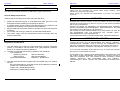
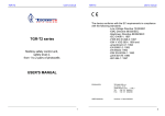
SB series User’s manual SB4 series Level 4 infrared safety barriers SB2 series Level 2 infrared safety barriers USER'S MANUAL SB series User’s manual SB series User’s manual SB series User’s manual READ AND UNDERSTAND THIS MANUAL INTRODUCTION This instruction Manual describes the SBx Safety Light Curtain (SLC). General Safety Requirements Always heed the following points when using the SBx SLCs: • • • • • Read this manual thoroughly to understand and make good use of the descriptions before installing and operating the product. A qualified person should conduct a risk assessment on the machine, and determine the suitability of this product before installation. Keep this Manual at the place where the operator can refer to it whenever necessary. Do not open the housing or make any unauthorised modifications. The power supply must be disconnected before proceeding with any external intervention. Regulations and Standards Regulations and Standards 1. The SBx safety light curtains are electro-sensitive protective equipment (ESPE) in accordance with European Union (EU) Machinery Directive Annex IV, B, Safety Components and Item 1. 2. The SBx complies with the following regulations and standards: (1) EU regulations Machinery Directive: Directive 98/37/EC EMC Directive: Directive 89/336/EEC (2) European standards: EN61496-1, prEN61496-2 3. The SBx received the following approvals from notified body TÜV Product Service: EC Type-Examination in accordance with the EU Machinery Directive TYPE 2 and 4 ESPE (EN61496-1), TYPE 2 and 4 AOPD (prEN61496-2) Certificate of a Notified Body for EMC Please read and understand this manual before storing, installing, operating, maintaining, or disposing of the product. Please consult your TECHNO GR representative if you have any questions or comments. WARRANTY TECHNO GR's exclusive warranty is that the products are free from defects in materials and workmanship for a period of one year (or other period if specified) from date of sale by TECHNO GR. TECHNO GR MAKES NO WARRANTY OR REPRESENTATION, EXPRESS OR IMPLIED, REGARDING NONINFRINGEMENT, MERCHANTABILITY, OR FITNESS FOR PARTICULAR PURPOSE OF THE PRODUCTS. ANY BUYER OR USER ACKNOWLEDGES THAT THE BUYER OR USER ALONE HAS DETERMINED THAT THE PRODUCTS WILL SUITABLY MEET THE REQUIREMENTS OF THEIR INTENDED USE. TECHNO GR DISCLAIMS ALL OTHER WARRANTIES, EXPRESS OR IMPLIED. LIMITATION OF LIABILITY TECHNO GR SHALL NOT BE RESPONSIBLE FOR SPECIAL, INDIRECT, OR CONSEQUENTIAL DAMAGES, LOSS OF PROFITS OR COMMERCIAL LOSS IN ANY WAY CONNECTED WITH THE PRODUCTS, WHETHER SUCH CLAIM IS BASED ON CONTRACT, WARRANTY, NEGLIGENCE, OR STRICT LIABILITY. In no event shall responsibility of TECHNO GR for any act exceed the individual price of the product on which liability is asserted. IN NO EVENT SHALL TECHNO GR BE RESPONSIBLE FOR WARRANTY, REPAIR, OR OTHER CLAIMS REGARDING THE PRODUCTS UNLESS TECHNO GR'S ANALYSIS CONFIRMS THAT THE PRODUCTS WERE PROPERLY HANDLED, STORED, INSTALLED, AND MAINTAINED AND NOT SUBJECT TO CONTAMINATION, ABUSE, MISUSE, OR INAPPROPRIATE MODIFICATION OR REPAIR. SB series User’s manual SB series User’s manual SUITABILITY FOR USE DEFINITION OF SYMBOLS TECHNO GR shall not be responsible for conformity with any standards, codes, or regulations that apply to the combination of products in the customer's application or use of the product. Information in this manual that is of particular importance can be identified as follows; At the customer's request, TECHNO GR will provide applicable third party certification documents identifying ratings and limitations of use that apply to the products. This information by itself is not sufficient for a complete determination of the suitability of the products in combination with the end product, machine, system, or other application or use. The following are some examples of applications for which particular attention must be given. This is not intended to be an exhaustive list of all possible uses of the products, nor is it intended to imply that the uses listed may be suitable for the products: • • • WARNING indicates a potentially hazardous situation, which, if not avoided, will result in minor or moderate injury, or may result in serious injury or death. Additionally there may be significant property damage. CAUTION indicates a potentially hazardous situation, which, if not avoided, will occasionally result in minor or moderate injury, or result in physical damage to property. NOTICE is used to emphasise essential information. Outdoor use, involving potential chemical contamination or electrical interference or conditions or use not described in this document. Nuclear energy control systems, combustion systems, railroad systems, aviation systems, medical equipment, amusement machines, vehicles, and installations subject to separate industry or government regulations. Systems, machines, and equipment that could present a risk to life or property. Please know and observe all prohibitions of use applicable to the products. NEVER USE THE PRODUCTS FOR AN APPLICATION INVOLVING SERIOUS RISK TO LIFE OR PROPERTY WITHOUT ENSURING THAT THE SYSTEM AS A WHOLE HAS BEEN DESIGNED TO ADDRESS THE RISKS, AND THAT THE TECHNO GR PRODUCT IS PROPERLY RATED AND INSTALLED FOR THE INTENDED USE WITHIN THE OVERALL EQUIPMENT OR SYSTEM. NOTE: Some specifications of the products may be changed without any notice. Special model numbers may be assigned to fix or establish key specifications for your application on your request. Please consult with your TECHNO GR representative at any time to confirm actual specifications of purchased products. MANUFACTURER: TECHNO-GR s.r.l. via Torino, 13/15 10046 Poirino (TO) - ITALY Tel. +39 011 9452041 FAX +39 011 9452090 E-Mail [email protected] WWW www.technogr.com USER’S MANUAL: Version 2..0 dated 29-03-2006 SB series User’s manual SB series User’s manual 11 GENERAL INFORMATION AND USEFUL DATA .......................... 41 INDEX 12 TECHNICAL SPECIFICATIONS...................................................... 42 section 1 2 3 4 5 6 page 13 DIMENSIONS ................................................................................... 45 OPERATION ......................................................................................9 14 NOTE:............................................................................................... 48 PRECAUTIONS AND CRITERIA FOR INSTALLATION ................10 2.1 CALCULATION OF THE MINIMUM DISTANCE FOR INSTALLATION ............... 10 2.2 REFLECTING SURFACES................................................................................... 12 MECHANICAL ASSEMBLY.............................................................16 CONNECTIONS ...............................................................................17 4.1 REFERENCES FOR CABLES:............................................................................. 17 4.2 NOTES ON CONNECTIONS................................................................................ 18 4.3 CODES AND SPECIFICATIONS OF AVAILABLE MODELS ............................... 19 4.4 DEFINITION OF CONTROLLED HEIGHT............................................................ 20 ALIGNMENT PROCEDURE ............................................................21 OPERATING PROCEDURES ..........................................................22 6.1 SETTING THE INTERNAL DIP-SWITCHES ........................................................ 22 6.1.1 SELECTION OF RESET MODE.................................................................... 22 7 MUTING, OVERRIDE AND FLOATING BLANKING FUNCTIONS 23 7.1 GENERAL INFORMATION ON THE THREE FUNCTIONS ................................. 23 7.2 MUTING FUNCTION ............................................................................................ 23 7.3 DESCRIPTION OF SINGLE MODULE MUTING AND MODULAR MUTING ....... 24 7.3.1 DEFINITION OF MODULE. ........................................................................... 24 7.3.2 SINGLE MODULE MUTING AND MODULAR MUTING ............................... 25 7.3.3 SELECTION OF MODULAR MUTING MODE (STANDARD) ....................... 25 7.3.4 SELECTION OF SINGLE MODULE MUTING............................................... 25 7.4 TIMING CONSTRAINTS (muting function) ........................................................... 31 7.5 Timing constraints (for SLCs with postfix “–MTL” at the ordering code) ............... 32 7.6 OVERRIDE ........................................................................................................... 33 7.6.1 ENABLING THE OVERRIDE FUNCTION ..................................................... 33 7.7 FLOATING BLANKING FUNCTION ..................................................................... 34 7.7.1 Definition of “Blanking” and of “Floating blanking” ......................................... 34 7.7.2 Alternative Blanking possibility....................................................................... 35 7.7.3 Blanking recording procedure ........................................................................ 37 8 LED DIAGNOSTICS.........................................................................38 8.1 LED’s Description.................................................................................................. 38 9 ROUTINE CONTROLS AND MAINTENANCE... Error! Bookmark not defined. 10 FINAL CHECKS AFTER INSTALLATION ......................................41 7 8 SB series 1 User’s manual SB series 2 OPERATION The Safety Light Curtain (SLC) is made up of one bar with transmitting optical elements called Transmitter (TX) and one with receiving optical elements called Receiver (RX). The photosensitive elements are regularly scanned in sequence along all its length. The operator has a multifunction pushbutton, which is used for the following: • TEST: If pressed during normal operation, it checks if all of the system, comprising of the SLC and the machine is working. Pressing the TEST button (opening the contact) basically simulates the interruption of one or more safety beams and it is possible to check that the machinery stops in the correct time and configuration. • RESTART: If pressed after an intervention by the SLC, (manual reset condition) the system will be reset. • ALIGNMENT: If the button is pressed when there is no power supply to the SLC and then power is restored, whilst the button is being pressed, it enters alignment mode, i.e. it provides an indication of the alignment position of the unit by means of two yellow LEDs. • OVERRIDE: (only present if the muting function is operational) if the button is pressed within 5 seconds of switching on and it is kept pressed for at least 5 seconds, the SLC will close the safety outputs if the beams are interrupted. This condition stops as soon as the button is released or automatically after 120 seconds. PRECAUTIONS AND CRITERIA FOR INSTALLATION The area where the SLC is to be installed must be compatible with the SLC ‘s technical specifications. The temperature of the environment, interference caused by electromagnetic disturbance and sources of light and such like, should be assessed a competent person. Please contact the manufacturer for any information not contained in this manual. 2.1 CALCULATION OF THE MINIMUM DISTANCE FOR INSTALLATION The safety distance ‘S’ must guarantee that the operator cannot reach the danger zone before the machinery with the moving parts has stopped. The formula to calculate the safety distance for multi-beam SLCs is as follows: S=(K*T)+C S T = safety distance. = T1 + T2 where T1 = machinery’s response time in seconds. T2 = barrier’s response time in seconds. K = approach speed of the body to the danger zone: 2000 mm/s for SBx models, 1600mm/s for SBx-K models C =8*(d-14)mm for SBx models, 850 mm for SBx-K models where d is the minimum object that can be detected (35mm for SBx and 14mm for SBx-HR) S 1. Automatic reset: After the SLC has detected an object, it returns to normal operation as soon as the object is removed. 2. Manual reset: Normal operating mode is only restored after the object has been removed and the reset button has been pressed. To enable the muting function, the LMS muting indicator must be connected when the SLC is not connected to the power supply, as shown in section 6, and then the SLC’s power supply must be restored. To disable the muting function, the LMS muting indicator must be disconnected when the SLC is not connected to the power supply, and then the SLC’s power supply restored. Please remember that by enabling/disabling the muting function the override function is automatically enabled/disabled. The outputs are PNP type. Should the load to be controlled have alternating current or require more than 250mA consumption, it is necessary to use an external safety relay module. 9 User’s manual H2 H1 S = safety distance. H1 = the bottom optical beam must not have a height above 400 mm. H2 = the top optical beam must not be below 900 mm. Table suitable only for body protection light curtains Number of beams 4 (SBx-K4 ) Heights above the reference plane, e.g. ground in mm 300, 600, 900, 1200 3 (SBx-K3) 300, 700, 1100 2 (SBx-K2 ) 400, 900 Reference from EN999 10 SB series User’s manual If the barriers are installed in a horizontal position, the optical bars must be installed so that the distance that exists between the danger zone and the furthest optical ray is equal to the result of the calculation using the formula, with the following parameters: S=(K*T)+C T= T1 + T2 where K C H T1 = machinery’s response time in seconds. T2 = barrier’s response time in seconds. = 1600 mm/s (approach speed of the body to the danger zone). = 1200 - 0.4 * H. = height of the optical rays compared to the floor. SB series 2.2 User’s manual REFLECTING SURFACES Be sure to install the SLC to minimize the effect of reflection from nearby surfaces. Serious injuries can result if these effects are not taken into consideration. Should there be any reflecting surfaces, the distance must be sufficient to safeguard against passive reflections. The distance can be calculated following the table below: where ‘D’ and ‘L’ are expressed in m reflecting surface S H S = safety distance. H = the optical beam must have a height between 225 mm and 1m. When Floating Blanking is used the system resolution change. Please refer to Floating blanking chapter for the variation SBx-K series do not use in a horizontal position S H 11 12 SB series User’s manual This table will help to calculate the distance between SLC and reflecting surfaces Use this table with SB2 and SB2-HR light curtains User’s manual If several SLCs are used, care must be taken that each SLC does not interfere with the ones nearby; please install as follows: RX1 0.5 to 3 m Minimum permitted installation distance D 0.26m Over 3 m L/2 x tan5° = L/2 x 0.088 (m) L distance between SLCs SB series TX1 TX2 RX2 Use this table with SB4 and SB4-HR light curtains 0.5 to 3 m Minimum permitted installation distance D 0.13m Over 3 m L/2 x tan2,5° = L/2 x 0.044 (m) L distance between SLCs Install the SLC so that they emit in the opposite directions (Staggered) RX1 TX2 RX1 TX1 TX2 RX2 Use this table with SB2-K light curtains 0.5 to 3 m Minimum permitted installation distance D 0.26m Over 3 m L/2 x tan 5° = L/2 x 0.088 (m) L distance between SLCs Use this table with SB4-KL and, over 4mt, SB4-K light curtains 0.5 to 3 m Minimum permitted installation distance D 0.13m Over 3 m L/2 x tan 2,5° = L/2 x 0.044 (m) L distance between SLCs TX1 RX2 All these installation will prevent mutual interference between SLC. 13 14 SB series User’s manual Insert a non-transparent wall if it is not possible to connect the SLC as shown previously. RX1 TX1 wall RX2 SB series 3 User’s manual MECHANICAL ASSEMBLY Use the appropriate brackets provided to complete the mechanical assembly. The securing brackets nuts c slide in the container’s grooves so the TX2 brackets d can be placed at an equal distance from each other. RX1 wall RX2 Fixing facilities list 1) Movable nuts (8pcs) 2) Fixing brackets (4pcs) 3) Washer (8pcs) 4) Grower (8pcs) 5) Nut (8pcs) TX1 TX2 The two bars must be mounted symmetrically as shown in the picture: Top view 15 16 SB series 4 4.1 User’s manual SB series 4.2 CONNECTIONS NOTES ON CONNECTIONS • REFERENCES FOR CABLES: • • • • • • • 17 User’s manual The transformer needed to power the system must comply with standard EN 60742 (dual isolation), or with equivalent isolation, e.g. VDE 0551, protective separation is required. The control unit must be protected with an external fuse, whose rated breaking current must be 1A. The TEST/RESTART button must be located so that the operator can see the protected area when restarting, testing or overriding. The external illuminated indicator for muting override enabled must be located so that it can be seen from all sides of operation. Read the section on the muting function and its use before locating the sensors for the activation of this function. Check that the load does not absorb current in excess of 250mA for each OSSD; in this case a protection device will intervene to limit the maximum current. If loads with currents in excess of 250mA for each OSSD or alternating current are to be controlled, please connect an external safety relay module. Muting input A and Muting input B can be provided by mechanical switch, photoelectric sensors, proximities switch, with closed contact in the presence of the object to be detected. The test connection must always be executed with a N.C. button or connected to an automatic device, such as a PLC. 18 SB series 4.3 User’s manual CODES AND SPECIFICATIONS OF AVAILABLE MODELS The columns with “Number of modules” and “Number of optical units per module” refer to operating management with muting (see section 9.3). The following table shows the standard models available in the SBx series, based on the length of the bars and their operating features: All models in the SB series guarantee 35 mm resolution. Height controlled mm Total height mm Total number of optical units Response time ms SBx-150 182 240 8 SBx-300 329 347 SBx-450 476 SBx-600 Number of modules Number of optical units per module 14 4 2 16 14 4 4 494 24 16 4 6 623 641 32 16 4 8 SBx-750 770 788 40 18 5 8 SBx-900 917 935 48 20 6 8 SBx-1200 1211 1229 64 22 4 16 SBx-1500 1505 1523 80 24 5 16 SBx-1650 1652 1670 88 26 4 22 Models The following table shows the standard (1) models available in the SBx-K series with variable resolution: Height controlled mm Total height mm Total number of optical units Response time ms Number of modules Number of optical units per module SBx-K-2-500 518 641 2 14 2 1 SBx-K-3-800 818 941 3 14 3 1 SBx-K-4-900 918 1041 4 14 4 1 SBx-K-4-1200 1218 1341 4 14 4 1 Models SB series User’s manual The following table shows the standard models available in the SBx-HR series, based on the length of bars and their operating features. All the models in the SBx-HR series guarantee 14 mm resolution. Height controlled mm Total height mm Total number of optical units Response time ms Number of modules Number of optical units per module SBx-HR-150 161 240 21 15 7 3 SBx-HR-300 308 347 42 18 7 6 SBx-HR-450 455 494 63 22 7 9 SBx-HR-600 602 641 84 24 6 14 SBx-HR-750 749 788 105 27 7 15 SBx-HR-900 896 935 126 30 6 21 SBx-HR-1200 1190 1229 168 36 8 21 SBx-HR-1500 1484 1523 210 42 10 21 SBx-HR-1650 1631 1670 231 45 11 21 Models 4.4 DEFINITION OF CONTROLLED HEIGHT Dimension indicated with “E” represent the height controlled by the light curtain. In this area every object with dimension equal to the resolution of light curtain can be seen. The “E – res” dimension indicate the effective sensing area of the light curtain. (1) Protected heights not included in the list of standard models can be supplied on request. 19 20 SB series 5 User’s manual ALIGNMENT PROCEDURE 6 After completing correct mechanical assembly and connections, as described in the previous sections, the SLC should be aligned as follows: • • • • • • • • SB series Disconnect the SLC’s power supply. Open the test/restart contact. Restore the SLC’s power supply. Adjust the direction of the SLC by moving the transceiver or the mirror. The 2 yellow LEDs located on the transceiver will both be lit when the SLC is aligned correctly. In addiction also the green guard LED will switch on and the red break LED will switch off After aligning the SLC, secure the bolts firmly. Disconnect the power supply. Restore the SLC’s power supply (with the test contact closed); it will enter operating mode. Complete all the tests described in section 9 (final checks) and those required for routine maintenance (section 10). 6.1 User’s manual OPERATING PROCEDURES SETTING THE INTERNAL DIP-SWITCHES • Disconnect the SLC’s power supply and remove the connector side RX, so that you can reach the two banks four-way dip-switches located there. • Use a suitably sized screwdriver to set the dip-switches as per the required configuration according to the following tables. 6.1.1 SELECTION OF RESET MODE Single switch number 4 Reset OFF Manual ON Automatic (default setting) ATTENTION In every unit there are two separate dip-switch banks. The two banks must be set in the same way to get a valid configuration. Single switch number 3 OFF ON No function DEFAULT SETTING NOT ALLOWED Dip switches number 1 and 2, act on the partial muting configuration. See “Partial muting configuration”. 21 22 SB series User’s manual 7 MUTING, OVERRIDE AND FLOATING BLANKING FUNCTIONS 7.1 7.3 GENERAL INFORMATION ON THE THREE FUNCTIONS The muting, override and floating blanking functions enable the barrier (or a part of it) to be bypassed when it is working for operational requirements. As required by current standards, the barrier is provided with inputs for the activation of these functions. It should however be remembered that these functions basically override the system and they should therefore be used with due care. 7.2 SB series MUTING FUNCTION As mentioned in the introduction, the muting function can be enabled with any SLC by simply connecting the LMS muting indicator when the SLC is switched off. The presence of this indicator is recognised when the SLC is switched on. If its presence is detected, the SLC will enable the muting function and if it is not present the SLC will ignore any request for muting. It is important to note that if the muting indicator is connected when the SLC is already connected to the power supply, it will not be recognised and the muting function will not be enabled. Once enabled, if the LMS muting indicator develops a fault or is removed without first disconnecting the SLC’s power supply, it will signal an error with the muting light, as described in section 10. User’s manual DESCRIPTION OF SINGLE MODULE MUTING AND MODULAR MUTING With this series of barriers it is possible to specify single module muting or modular muting function at the moment of purchase. There follows a brief description of these two types of muting. 7.3.1 DEFINITION OF MODULE. Module means a portion of barrier whose size can contain the amount of optical units per module defined in the table in section 6. For example, a SBx-600 should be considered as 4 adjacent modules, each containing 8 optical units for a total of 32 optical units, whereas a SBx-HR-300 should be considered as 7 adjacent modules, each containing 6 optical units for a total of 42 optical units. Various configurations can be achieved on request, according to requirements. The layout of the modules is illustrated below: Umpteen module 4th module To disable the muting function, the power supply must be turned on without the LMS muting indicator connected. In brief: this function, present on all SLC s, is enabled and disabled by means of the following simple procedure: 3rd module Disconnect the SLC’s power supply. Connect the appropriate LMS muting indicator and the muting sensors (see section 6) - Restore the SLC’s power supply. Bypass the muting function as follows. - Disconnect the SLC’s power supply. - Disconnect the LMS muting indicator and the muting sensors (see section 6) Restore the SLC’s power supply - 2nd module 1st module Connector 23 Connector 24 SB series User’s manual 7.3.2 SINGLE MODULE MUTING AND MODULAR MUTING Single module muting enables only one module at a time to be made transparent according to requirements, whereas modular muting makes it possible to make the sum of two or more modules transparent, until even the whole barrier has been bypassed. Should a muting request be made for modules that are not managed when in single module muting mode (for example bypassing of the 4th module with a barrier that manages only three), the barrier will remain operational. Please note that in single module muting is not possible to select the module containing the optic ray placed in the opposite side opf connector. In that case the muting function will not work properly. Should a modular muting request also involve modules that are not managed (for example muting of modules 1+2+3 with a barrier that manages only two), the barrier will enter total muting mode There follow the settings for the various muting modes. 7.3.3 SELECTION OF MODULAR MUTING MODE (STANDARD) Single switch 1° 2° OFF OFF OFF ON ON OFF ON ON 7.3.4 • • User’s manual The single module muting function must be requested in the purchase order. The single module muting function excludes the modular muting function. Take adequate care when installing the muting sensors to prevent undesired requests for muting: 1. Wiring must be done correctly. 2. The muting sensors must recognise the whole length of the material (i.e. pallets, vehicles...). 3. The sensors must be arranged so that the material is also recognised if it has to be lifted for processing. 4. The effect of various transportation speeds in the field of muting on the overall duration of muting must be taken into account, if any. 5. All the safety photocells and muting sensors must be arranged so that the previous material clears the last muting sensor before the new material reaches the first sensors Modular muting Muting of all modules (standard total muting) Muting of modules 1+2+3 Muting of modules 1+2 Muting of modules 1 SLC SELECTION OF SINGLE MODULE MUTING Single switch 1° 2° OFF OFF OFF ON ON OFF ON ON Muting of single module Muting of module 1 Muting of module 2 Muting of module 3 Muting of module 4 B2 WARNING In every unit are present two different dip-switch banks and that two banks must be set in the same way. • SB series A2 B1 A1 Example of conveyor protection installation, which must allow a box to pass through but not a person. The SLC is connected to the control panel, and A1, A2, B1 and B2 are sensors used to enable muting. The contacts for these sensors are controlled on the transceiver unit. Sensors A1, A2, B1 and B2 can be optical, mechanical or proximity sensors etc., with closed contact in the presence of the object to be detected. The modular muting function with all modules activated is setted by factory as default. 25 26 SB series User’s manual The following drawings show several examples of configurations with the use of the muting function: SB series User’s manual Application with four sensors and single direction for material exit: Application with four sensors – ‘Bi directional muting’ B2 A2 B2 SLC B1 A2 SLC B1 A1 D a n g e r o u s A1 D a n g e r o u s D1 D1 z o n e D2 D Electrical connection of muting input z o n e D2 D Electrical connection of muting input +24Vdc +24Vdc Input of A1 sensor Input of A1 sensor Muting input A (Green – 3) Input of A2 sensor Muting input A (Green – 3) Input of A2 sensor Muting input B (Yellow – 4) Muting input B (Yellow – 4) Input of B1 sensor Input of B1 sensor Input of B2 sensor Input of B2 sensor 27 28 SB series User’s manual Application with two sensors and single direction for material exit: This muting activation sequence is only available for SLCs with postfix “–MTL” at the ordering code. SLC B1 D1 A1 D a n g e r o u s z o n e D2 D SB series User’s manual Where: D: minimum dimension of package that can cross the SLC. D1: distance between muting actuator B and SLC. It MUST be as short as possible. Minimum distance allowable depends on the speed of conveyour, the response time of SLC and response time of muting actuator. D2: Distance between muting actuator A and muting actuator B. It must be > 250mm It also depends on the conveyour speed: dmax [cm]= v[m/s] * 3[s] * 100 > 25 It is necessary that this distance does not allow both sensors to be activated and thus muting if a person goes through by accident. Muting lamp Start & Test buttons Cable to lamp Supply Cable Muting cable Electrical connection of muting input +24Vdc Protect cables RX cable TX cable Muting input A (Green – 3) Input of A1 sensor Muting input B (Yellow – 4) Input of B1 sensor 29 30 SB series • • • • 7.4 User’s manual The TEST/RESTART button must be located so that the operator can see the protected area when restarting, testing or overriding. The external illuminated indicator for muting override enabled must be located so that it can be seen from all sides of operation. If the muting sensors are installed very close to the SLC, care must be taken that the receivers of the sensors are mounted on the mirror side of the SLC in order to avoid interference. The system is protected against the possibility of faults due to damage to the wires; however we recommend laying the cables for all connections in order to avoid damage to the connection cables. TIMING CONSTRAINTS (muting function) a) The muting request must take place with the correct timing sequence: the Muting A input must be enabled first and then the Muting B input. The request for the latter must be made within a maximum of 3 seconds and not before 30 ms (TM) after enabling Muting A input. Otherwise the muting function will not be enabled. An incorrect sequence on the muting inputs will not start the muting process. b) Muting status can be maintained for an unlimited period of time as long as the muting signals are valid. SB series 7.5 User’s manual Timing constraints (for SLCs with postfix “–MTL” at the ordering code) a) The muting request must take place with the correct timing sequence: the Muting A input must be enabled first and then the Muting B input. The request for the latter must be made within a maximum of 3 seconds and not before 30 ms after the enabling of the Muting A input. Otherwise the muting function will not be enabled. An incorrect sequence on the muting inputs will not start the muting process. b) There are 5 seconds maximum from the activation of muting to the package entrance in the protected area by interrupting the SLC. If this time is exceeded, muting function will stop immediately. c) As long as a package interrupts the protected area (at least one beam), the muting function is maintained d) Muting status can be maintained for an unlimited period of time as long as the muting signals are valid. Timing chart SLC Timing chart Free Interrupted SLC F re e OSSD ON In te rru p te d OSSD OFF ON Muting Input A OFF M u tin g In p u t A OFF ON OFF M u tin g In p u t B Muting Input B ON ON OFF OFF M u tin g S ta tu s ON Muting Status A c tiv e Active OFF OFF 0 .0 3 s e c < T m < 3 s e c 0.03 sec < Tm < 3sec Ts< 5 sec A muting request cannot be made if the SLC outputs are open, that is to say when the beams have been interrupted. 31 32 SB series 7.6 User’s manual OVERRIDE This function makes it possible to override or bypass the system. It is used to start up the machine after the material has interrupted one or more of the SLC beams and to free the protected area from any material that is present in front of the SLC, If a pallet has stopped in front of the protected area, it will not be possible to restart the conveyor belt because the SLC detects one or more beams have been interrupted and therefore will not close the outputs; therefore the protected area cannot be cleared. However, it can be cleared if the override function is enabled. This function can be used for all SLCs with the LMS muting indicator connected, as described in section 3. 7.6.1 ENABLING THE OVERRIDE FUNCTION • Switch the appliance off. • Switch it on again and press the test/restart button within 5 seconds, keeping it pressed for at least 5 seconds. • The override function is now enabled. The LMS muting indicator flashes to signal the exclusion of the SLC. • The maximum duration of the override function is 120 seconds, after which the SLC is reset, even if the button is kept pressed. Naturally, if the button is released before this, the override function will terminate immediately. SB series 7.7 User’s manual FLOATING BLANKING FUNCTION 7.7.1 Definition of “Blanking” and of “Floating blanking” For Blanking we mean the permanent masking of a determined number of optical elements in a well-defined part of the sensitive zone of the barrier. This can be caused for example from a part of the machine that permanently obscures a part of the barrier. To allow to the connected machine to operate in safety condition the barrier must recognize the masking object as a conventional situation and lock the machine as soon as other optical are obscured, for example by a hand or a body of a person. The blanking function is a feature that allows the interdiction of some rays of the barrier without locking the machine. If the object that covers the optical is free of moving lengthwise on the barrier optical range, it masks different optical during its movement. In this case we talk about floating blanking and the barrier functionality that allows this movement is the floating blanking function. blanking floating blanking Most of cases the object covers more than one optical. The maximum number of optical elements that can be simultaneous masked is limited (for safety reasons) and depends on the total number of optical elements in the barrier. The masked optical can't exceed 30% of the total optical elements, and anyway can’t be more of 20 optical masked. Examples: 1) total optical elements = 24 optical elements available for Blanking = 7 33 34 SB series User’s manual The zone that can be masked will have max 7 optical elements. 2) total optical elements = 105 optical elements available for Blanking = 31 SB series User’s manual In the case which It’s sure that the object will cover just one optical more of the starting position it’s useful that the barriers allows just the +1. This is the case for example of an object that during its rotation covers one more optical. The zone that can be masked will have max 20 optical elements, even if 30% of the total would be 31. 7.7.2 Alternative Blanking possibility To set the blanking function is necessary that the barrier recognises the object length as explained in above paragraph. In case of floating blanking the number of covered optics depends, besides to the object length, also to the starting position of the object. To cover an optical is necessary to completely cover his beam; the beams appear as equally spaced cylinders as shown in the following figure. The following table resume all the selectable blanking modes. beams Consider as example an object able to cover three optical beams: the initial number of covered optical depends from its starting position. starting position at 3 covered optical In similar cases is better set the barrier in the “+1 floating blanking“ mode. If the object doesn’t moving the barrier can be set in the “fixed blanking” mode, if no blanking is needed it can be set in the “no blanking” mode. The blanking mode can be selected setting the dip switches on the receiver motherboard (see paragraph operating procedures). starting position at 2 covered optical During the object movement could happen that (in some moments) in the first case only 2 optical are obscured, in the second case instead there are three optical covered. So the barrier must allow a number of covered optical equal to the starting number -1 in the first case and +1 in the second case. Since the starting positions of the object can be different the barrier must allow the +1 and -1 at the same time. This functionality is called “±1 floating blanking“. 35 blanking mode n. of beams that can be masked ±1 floating blanking (default) dip switch pos. resolution N.1 N.2 HR ST dimension of object ± 1 beam off off 28 mm 70 mm +1 floating blanking dimension of object + 1 beam off on 21 mm 51 mm fixed blanking dimension of object on off 14 mm 35 mm no blanking none on on 14 mm 35 mm The resolution (the minimal dimension of an object placed across the curtain that cause the machine shutdown) depends from the selected blanking mode: it decreases increasing the “optic tolerance” (the +1 or the ±1) embodied from the type of blanking. In a standard resolution barrier (ST) the resolution is halved (the object dimension is doubled) respect to a high resolution (HR) because the distance between the optical elements is double (7 mm for a HR, 14 mm for a ST). 36 SB series 7.7.3 User’s manual SB series User’s manual Blanking recording procedure 8 LED DIAGNOSTICS To record the object, proceed as follows: 1. 2. 3. 4. 5. 6. 7. 8. 9. Turn the power of the barrier off, Position the object to determine the Blanking area. Connect Muting input A to the 24Vdc. Make sure that the contact of the Test/Reset button is closed. Power the barrier again. Now connect the 24Vdc to the MUTING B input. The recording of the object is indicated by the yellow LOWER led blinking, which also confirms the successful recording of the Blanking. If the led doesn't blink in this phase it means that the object activates over 30% of optical elements present Disconnect the Muting A and Muting B inputs from the +24Vdc. Make sure the barrier is functioning correctly in the Blanking configuration, with the yellow LOWER led blinking. The optical element opposite the connector cannot be used in the Blanking function because it is the optical element for the synchronism between the two barriers. If a Blanking recording is done without the object, and therefore with the beams free, at the end of the operations the yellow LOWER led won't blink because all of the barrier is active; this is a simple way to reset the Blanking recording. If the object recorded is removed for some reason, or occupies a number of optical elements which is lower with respect to the recording situation, the barrier will indicate an anomaly and the outputs will be de-energized. To indicate this particular condition, the LOWER (yellow) and BREAK (red) led blink. Solve this error by pressing and releasing the TEST/RESET button on the condition that the object has been replaced. 8.1 LED’s Description The operator is able to recognise the operating status of the SLC by means of five LED located on the SLC. The status of the LED indicates the following: (looking at the front of the transceiver from right to left) Basic understanding of LED indicators Disposition of indicator Name of indicator Colour Power Green Lower Yellow Guard Green Break Red Upper Yellow LED signal Pattern Normal Operation LED signal Pattern Description OSSD ON OSSD OFF, object in the field Interlock, waiting for test button pressure Correctly aligned in aligning procedure Dust indication, probable lost of signal due to dust on the front cover A short circuit on OSSD is present Floating blanking correctly activated 37 38 SB series User’s manual SB series 9 Faulty conditions LED signal Pattern User’s manual ROUTINE CONTROLS AND MAINTENANCE These checks are recommended and should be carried out on a regular basis by qualified personnel: Description Power supply is too low 1) Micro controller fault 2) Fault on output system Muting lamp connection fault or muting lamp burned 3) Optical defect Floating blanking error 4) 5) Check that the SLC remains blocked by inserting an object that intercepts the beams along the entire length of the protected area. Check via the opening of the TEST/RESTART contact, that the safety outputs open (red LED lit and controller machinery stopped). Check that it is not possible to access the danger areas of the machinery from any area that is not protected and that the minimum distance between the dangerous areas and the SLC is no less than that calculated as per formulas 4.1 and 4.2.) Check that it is not possible for a person to get between the SLC and the dangerous parts of the machinery. Check that there is no external damage to the SLC and/or to the external electrical connections. Repeat checks 1 and 2 daily. Repeat checks 1 to 5 every 6 month maximum. The interval between the above actions can be shorter depends on the individual application and the environmental conditions where the SLC is used. 39 40 SB series User’s manual 10 FINAL CHECKS AFTER INSTALLATION • • SB series User’s manual 12 TECHNICAL SPECIFICATIONS Check that the area protected by the SLC is free of obstacles. Check that the safety outputs open correctly by interrupting the protection beams (BREAK LED lit, machinery under control stops). ITEM Rated operating distance 0,2m … 6m SBx-HR model 0,2m … 15m SBx-model 0.2m … 25m SB4-KL model 4m … 50m SB4-K model 0.5m … 50m SB2-K model Emitted light source Infrared LED (880 nm) Ambient light immunity According to IEC61496-2 beam pitch (center) SBx-K2-500 Æ 500mm SBx-K3-800\SBx-K4-1200 Æ 400mm SBx-K4-900 Æ 300mm SBx Æ 18mm SBx-HR Æ 7mm number of beams See table of available models protective height See table of available models EAA According to IEC 61496-2 11 GENERAL INFORMATION AND USEFUL DATA Everyone MUST be aware of issues regarding safety. Safety devices are only useful if they are installed correctly according to the recommendations set down by regulations. If you are not sure that you are able to install safety devices correctly, you should contact our service department or have them installed by a professional. This appliance is covered by a total warranty for 12 months from the date of its delivery. Faults that were clearly caused by damage due to incorrect use, accidental circumstances or catastrophic events are not covered by the guarantee. In case of faults, please send the SLC to: TECHNO-GR via Torino, 13/15 10046 Poirino (TO) - ITALY Tel. +39 011 9452041 FAX. +39 011 9452090 E-Mail [email protected] Indicators Receiver: A description of the fault found and the period of use must always accompany the appliance. Transmitter Dimensions (width x depth) Length 41 SPECIFICATION 2 green LEDS 2 yellow LEDS 1 red LED 1 green LED 1 yellow LED Profile: 35*45mm +2mm for connector part See Mechanical drawings 42 SB series User’s manual ITEM Materials Housing Front panel Sealing gasket Connector parts SB series SPECIFICATION Powder-coated aluminum, Polycarbonate EPDM (synthesis rubber) Metal: Galvanized brass Plastic: PVC User’s manual ITEM SPECIFICATION Outputs PNP Output circuit protection PNP short circuit protected Output current 250 mA each OSSD Max. Capacitive load 200nF (pure capacitive load) Output voltage drop < 2.0 V (excl. voltage drop due to cable extension) Housing color Yellow, RAL 1023 Connection M12 connector, 8-pole M12 connector 4 pole Operation temperature range - 10 °C ... + 55 °C Residual current < 100 µA Storage temperature range - 25 °C ... + 70 °C Circuit protection Relative humidity 15 % ... 95 % RH (no condensing) Reverse polarity, Overload Short-circuit (pulsed) Enclosure rating (EN 60529) IP 65 Input circuit Logical Zero level 0 – 8V Logical One level 14 – 24Vdc Pollution degree II Input pulse duration Min. 2 cycle time Installation category II process control equipment Response time See table of available models Altitude Up to 2000m External controls Test/Restart Muting and override Reset time (TOFF ÆTON) (interlock) ≤ 300ms Resistance to Vibration (to IEC 68-2-6) Shock (to IEC 68-2-27) 10 – 55 Hz ± 0.35mm amplitude, X, Y, Z directions 10G, 16ms, X, Y, Z direction Insulation resistance 800 MΩ @ 500Vdc Dielectric voltage strength 350Vac, 50/60 Hz (1 min) Rated operating voltage + 24 Vdc (± 20%) Configuration Manual reset / Automatic reset (default) Operating voltage range +19.2 … 28.8Vdc Operating modes Muting / Override (by wiring setting) Current consumption < 420mA (muting lamp included) Power-on delay < 800ms 43 44 SB series User’s manual SB series User’s manual Fixing movable bolt 13 DIMENSIONS All dimensions are shown in millimeters Fixing bracket 45 46 SB series User’s manual SB series Light curtains specification User’s manual 14 NOTE: E Models A L Height controll ed mm Total height mm SBx-150 53 182 240 SBx-300 53 329 347 SBx-450 53 476 494 SBx-600 53 623 641 SBx-750 53 770 788 SBx-900 53 917 935 SBx-1200 53 1211 1229 SBx-1500 53 1505 1523 SBx-1650 53 1652 1670 SBx-K-2-500 110 518 641 SBx-K-3-800 110 818 941 SBx-K-4-900 110 918 1041 SBx-K-4-1200 110 1218 1341 SBx-HR-150 47.5 161 240 SBx-HR-300 47.5 308 347 SBx-HR-450 47.5 455 494 SBx-HR-600 47.5 602 641 SBx-HR-750 47.5 749 788 SBx-HR-900 47.5 896 935 SBx-HR-1200 47.5 1190 1229 SBx-HR-1500 47.5 1484 1523 SBx-HR-1650 47.5 1631 1670 47 48