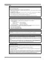
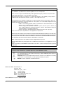
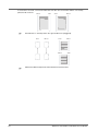
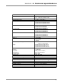
1
Cat.No. E45E-EN-02
F3S-TGR-SB4-KxC
F3S-TGR-SB2-KxC
Type
yp 4 Safety
y Light
g Curtain
Type 2 Safety Light Curtain
Introduction
INTRODUCTION
This instruction Manual describes the F3S-TGR-SBx-KxC Safety Light Curtain (SLC).
General Safety Requirements
Always heed the following points when using the F3S-TGR-SBx-KxC:
•
Read this manual thoroughly to understand and make good use of the descriptions before installing
and operating the product.
•
A qualified person should conduct a risk assessment on the machine, and determine the suitability of
this product before installation.
•
Keep this Manual at the place where the operator can refer to it whenever necessary.
•
Do not open the housing or make any unauthorised modifications.
•
The power supply must be disconnected before proceeding with any external intervention.
Regulation and Standards
1. The F3S-TGR-SBx-KxC safety light curtains are electro-sensitive protective equipment (ESPE) in accordance with European Union (EU) Machinery Directive Annex IV, B, Safety Components and Item 1.
2. The F3S-TGR-SBx-KxC complies with the following regulations and standards:
(1) EU regulations
Machinery Directive: Directive 98/37/EC
EMC Directive:
Directive 89/336/EEC
(2) European standards:
EN61496-1, prEN61496-2
3. The F3S-TGR-SBx-KxC received the following approvals from notified body TÜV Product Service:
EC Type-Examination in accordance with the EU Machinery Directive
TYPE 2 and 4 ESPE (EN61496-1),
TYPE 2 and 4 AOPD (prEN61496-2)
Certificate of a Notified Body for EMC
READ AND UNDERSTAND THIS MANUAL
Please read and understand this manual before storing, installing, operating, maintaining, or disposing of
the product.
Please consult your TECHNO GR representative if you have any questions or comments.
WARRANTY
TECHNO GR's exclusive warranty is that the products are free from defects in materials and workmanship
for a period of one year (or other period if specified) from date of sale by TECHNO GR.
TECHNO GR MAKES NO WARRANTY OR REPRESENTATION, EXPRESS OR IMPLIED, REGARDING
NONINFRINGEMENT, MERCHANTABILITY, OR FITNESS FOR PARTICULAR PURPOSE OF THE PRODUCTS.
ANY BUYER OR USER ACKNOWLEDGES THAT THE BUYER OR USER ALONE HAS DETERMINED
THAT THE PRODUCTS WILL SUITABLY MEET THE REQUIREMENTS OF THEIR INTENDED USE.
TECHNO GR DISCLAIMS ALL OTHER WARRANTIES, EXPRESS OR IMPLIED.
LIMITATION OF LIABILITY
TECHNO GR SHALL NOT BE RESPONSIBLE FOR SPECIAL, INDIRECT, OR CONSEQUENTIAL DAMAGES, LOSS OF PROFITS OR COMMERCIAL LOSS IN ANY WAY CONNECTED WITH THE PRODUCTS,
WHETHER SUCH CLAIM IS
BASED ON CONTRACT, WARRANTY, NEGLIGENCE, OR STRICT LIABILITY.
In no event shall responsibility of TECHNO GR for any act exceed the individual price of the product on
which liability is asserted.
IN NO EVENT SHALL TECHNO GR BE RESPONSIBLE FOR WARRANTY, REPAIR, OR OTHER CLAIMS
REGARDING THE PRODUCTS UNLESS TECHNO GR'S ANALYSIS CONFIRMS THAT THE PRODUCTS
WERE PROPERLY HANDLED, STORED, INSTALLED, AND MAINTAINED AND NOT SUBJECT TO
CONTAMINATION, ABUSE, MISUSE, OR INAPPROPRIATE MODIFICATION OR REPAIR.
3
SUITABILITY FOR USE
TECHNO GR shall not be responsible for conformity with any standards, codes, or regulations that apply to
the combination of products in the customer's application or use of the product.
At the customer's request, TECHNO GR will provide applicable third party certification documents identifying ratings and limitations of use that apply to the products.
This information by itself is not sufficient for a complete determination of the suitability of the products in
combination with the end product, machine, system, or other application or use.
The following are some examples of applications for which particular attention must be given. This is not
intended to be an exhaustive list of all possible uses of the products, nor is it intended to imply that the uses
listed may be suitable for the products:
• Outdoor use, involving potential chemical contamination or electrical interference or conditions or use not described in this document.
• Nuclear energy control systems, combustion systems, railroad systems, aviation systems, medical equipment, amusement machines, vehicles, and installations subject to
separate industry or government regulations.
• Systems, machines, and equipment that could present a risk to life or property.
Please know and observe all prohibitions of use applicable to the products.
NEVER USE THE PRODUCTS FOR AN APPLICATION INVOLVING SERIOUS RISK TO LIFE OR PROPERTY WITHOUT ENSURING THAT THE SYSTEM AS A WHOLE HAS BEEN DESIGNED TO ADDRESS
THE RISKS, AND THAT THE TECHNO GR PRODUCT IS PROPERLY RATED AND INSTALLED FOR
THE INTENDED USE WITHIN THE OVERALL EQUIPMENT OR SYSTEM.
Note: Some specifications of the products may be changed without any notice.
Special model numbers may be assigned to fix or establish key specifications for your application on your
request.
Please consult with your TECHNO GR representative at any time to confirm actual specifications of purchased products.
DEFINITION OF SYMBOLS
Information in this manual that is of particular importance can be identified as follows;
!
!
)
WARNING indicates a potentially hazardous situation, which, if not avoided, will result in minor or moderate injury, or may result in serious injury or death. Additionally there may be significant property damage.
CAUTION indicates a potentially hazardous situation, which, if not avoided, will occasionally
result in minor or moderate injury, or result in physical damage to property.
NOTICE is used to emphasise essential information.
MANUFACTURER: TECHNO-GR s.r.l.
via Torino, 13/15
10046 Poirino (TO) - ITALY
Tel.
+39 011 9452041
FAX
+39 011 9452090
E-Mail [email protected]
WWW www.technogr.com
USER'S MANUAL: Version 5.1 dated 29-3-2006
4
INDEX
Section
Page
1
Operation . . . . . . . . . . . . . . . . . . . . . . . . . . . . . . . . . . . . . . . . . . . . 7
2
Precautions and criteria for installation . . . . . . . . . . . . . . . . . . . . . . . . . . . 8
2-1
Calculation of the minimum distance for installation . . . . . . . . . . . . . . . . 8
2-2
Reflecting surfaces. . . . . . . . . . . . . . . . . . . . . . . . . . . . . . . . . 9
3
Mechanical Assembly . . . . . . . . . . . . . . . . . . . . . . . . . . . . . . . . . . . . . 12
4
Connections . . . . . . . . . . . . . . . . . . . . . . . . . . . . . . . . . . . . . . . . . . 13
4-1
Reference for cables . . . . . . . . . . . . . . . . . . . . . . . . . . . . . . . . 13
4-2
Notes on connections . . . . . . . . . . . . . . . . . . . . . . . . . . . . . . . 13
5
Alignment Procedure . . . . . . . . . . . . . . . . . . . . . . . . . . . . . . . . . . . . . 14
6
Operating procedures . . . . . . . . . . . . . . . . . . . . . . . . . . . . . . . . . . . . . 15
6-1
Setting the internal DIP-Switches . . . . . . . . . . . . . . . . . . . . . . . . . 15
6-1-1
Selection of reset mode . . . . . . . . . . . . . . . . . . . . . . . 15
7
Muting and override functions . . . . . . . . . . . . . . . . . . . . . . . . . .
7-1
General information . . . . . . . . . . . . . . . . . . . . . . . . . .
7-2
Muting function . . . . . . . . . . . . . . . . . . . . . . . . . . . . .
7-3
Partial muting configuration . . . . . . . . . . . . . . . . . . . . . .
7-4
Criteria for installation . . . . . . . . . . . . . . . . . . . . . . . . .
7-5
Timing constants (muting function) . . . . . . . . . . . . . . . . . .
7-6
Timing constraints (for SLCs with postfix "-MTL" at the ordering code)
7-7
Override . . . . . . . . . . . . . . . . . . . . . . . . . . . . . . . .
7-7-1
Enabling the Override Function . . . . . . . . . . . . .
8
LED diagnostics . . . . . . . . . . . . . . . . . . . . . . . . . . . . . . . . . . . . . . . . 23
8-1
LED's Description . . . . . . . . . . . . . . . . . . . . . . . . . . . . . . . . . 23
9
Routine controls and maintenance . . . . . . . . . . . . . . . . . . . . . . . . . . . . . . 25
10
Final checks after installation . . . . . . . . . . . . . . . . . . . . . . . . . . . . . . . . . 26
11
General information and useful data . . . . . . . . . . . . . . . . . . . . . . . . . . . . . 28
12
Technical specifications . . . . . . . . . . . . . . . . . . . . . . . . . . . . . . . . . . . . 29
13
Dimensions . . . . . . . . . . . . . . . . . . . . . . . . . . . . . . . . . . . . . . . . . . . 31
14
Note . . . . . . . . . . . . . . . . . . . . . . . . . . . . . . . . . . . . . . . . . . . . . . . 32
INDEX
.
.
.
.
.
.
.
.
.
.
.
.
.
.
.
.
.
.
.
.
.
.
.
.
.
.
.
.
.
.
.
.
.
.
.
.
.
.
.
.
.
.
.
.
.
. 16
. 16
. 16
. 17
. 18
. 21
. 21
. 22
. 22
5
6
INDEX
Section 1: Operation
The Safety Light Curtain (SLC) is made up of one active side with transmitter and receiver optical elements
called the transceiver and one completely passive side, with a mirror system.
The operator has a multifunction pushbutton, which is used for the following:
•
TEST: If pressed during normal operation, it checks if all of the system, comprising of the SLC and the
machine is working. Pressing the TEST button (opening the contact) basically simulates the interruption
of one or more safety beams and it is possible to check that the machinery stops in the correct time and
configuration.
•
RESTART: If pressed after an intervention by the SLC, (manual reset condition) the system will be
reset.
•
ALIGNMENT: If the button is pressed when there is no power supply to the SLC and then power is
restored, whilst the button is being pressed, it enters alignment mode, i.e. it provides an indication of the
alignment position of the unit by means of two yellow LEDs.
•
OVERRIDE: (only present if the muting function is operational) if the button is pressed within 5 seconds
of switching on and it is kept pressed for at least 5 seconds, the SLC will close the safety outputs if the
beams are interrupted. This condition stops as soon as the button is released or automatically after
120 seconds.
1.
2.
Automatic reset: After the SLC has detected an object, it returns to normal operation as soon as the object is removed.
Manual reset: Normal operating mode is only restored after the object has been removed and the reset
button has been pressed.
To enable the muting function, the LMS muting indicator must be connected when the SLC is not connected to the power supply, as shown in section 6, and then the SLC's power supply must be restored. To
disable the muting function, the LMS muting indicator must be disconnected when the SLC is not connected to the power supply, and then the SLC's power supply restored.
Please remember that by enabling/disabling the muting function the override function is automatically enabled/disabled.
The outputs are PNP type.
Should the load to be controlled have alternating current or require more than 250 mA consumption, it is necessary to use an external safety relay module.
7
Section 2: Precautions and criteria for installation
The area where the SLC is to be installed must be compatible with the SLC 's technical specifications. The
temperature of the environment, interference caused by electromagnetic disturbance and sources of light
and such like, should be assessed a competent person. Please contact the manufacturer for any information
not contained in this manual.
2-1
Calculation of the minimum distance for installation
The safety distance 'S' must guarantee that the operator cannot reach the danger zone before the machinery
with the moving parts has stopped. The formula to calculate the safety distance for multi-beam SLCs is as
follows:
S = (K * T) + C
S = safety distance.
T = T1 + T2
where T1 = machinery's response time in seconds.
T2 = SLC's response time in seconds.
K = 1600 mm/s (approach speed of the body to the danger zone).
C = 850 mm
S
H2
H1
S = safety distance.
H1 = the bottom optical beam must not have a height above 400 mm.
H2 = the top optical beam must not be below 900 mm.
Number of beams
4 (F3S-TGR-SBx-K4C)
3 (F3S-TGR-SBx-K3C)
2 (F3S-TGR-SBx-K2C)
Heights above the reference plane, e.g. ground in mm
300, 600, 900, 1200
300, 700, 1100
400, 900
Reference from EN999
! Do not use F3S-TGR-SBx-KxC series in
horizontal position.
S
H
8
2-1 Calculation of the minimum distance for installation
2-2
Reflecting surfaces
!
Be sure to install the SLC to minimize the effect of reflection from nearby surfaces. Serious injuries
can result if these effects are not taken into consideration.
Should there be any reflecting surfaces, the distance must be sufficient to safeguard against passive
reflections.
The distance can be calculated following the table below:
where 'D' and 'L' are expressed in m
Reflecting surface
Model
F3S-TGR-SB2-KxC
F3S-TGR-SB4-KxC
L distance between SLCs
0.5 to 3 m
Over 3 m
0.5 to 3 m
Over 3 m
2-2 Reflecting surfaces
Minimum permitted installation distance D
0.26 m
L/2 x tan5° = L/2 x 0.088 (m)
0.13 m
L/2 x tan5° = L/2 x 0.044 (m)
9
If several SLCs are used, care must be taken that each SLC does not interfere with the ones nearby;
please install as follows:
Mirror1
)
Mirror1
10
SLC2
Mirror2
Install the SLC so that they emit in the opposite directions (Staggered)
SLC1
)
SLC1
Mirror2
SLC1
Mirror1
Mirror2
SLC2
SLC2
All these installation will prevent mutual interference between SLC.
Section 2: Precautions and criteria for installation
!
Insert a non-transparent wall if it is not possible to connect the SLC as shown previously.
SLC1
Mirror1
SLC1
wall
wall
Mirror1
)
SLC2
Mirror2
SLC2
Mirror2
The two bars must be mounted symmetrically as shown in the picture:
Top view
2-2 Reflecting surfaces
11
Section 3: Mechanical Assembly
Use the appropriate brackets provided to complete the mechanical assembly.
The securing brackets nuts A slide in the container's grooves so the brackets B can be placed at an equal
distance from each other.
Fixing facilities list
1) Movable nuts (8pcs)
2) Fixing brackets (4pcs)
3) Washer (8pcs)
4) Grower (8pcs)
5) Nut (8pcs)
0 - 15.7
37.3
47.3
25.6
37.6
12
6.5
Section 4: Connections
4-1
Reference for cables
The test connection must always be executed with a N.C. button or connected to an automatic device, such
as a PLC.
TRANSCEIVER
OUT 1
OUT 2
RL 500 mA max.
GRAY PINK
RL 500 mA max.
Muting B
LMS
Muting A
Test/Restart
0 VDC
24 VDC
Shield
SHIELD BROWN BLUE WHITE GREEN YELLOW RED
Connection with muting function activate
TRANSCEIVER
OUT 2
RL 500 mA max.
OUT 1
GRAY PINK
RL 500 mA max.
N.C.
N.C.
N.C.
Test/Restart
0 VDC
24 VDC
Shield
SHIELD BROWN BLUE WHITE GREEN YELLOW RED
Connection with muting function disabled
Wire color
White
Brown
Green
Yellow
Gray
Pink
Blue
Red
4-2
Notes on connections
!
•
!
•
)
)
)
•
•
The external illuminated indicator for muting override enabled must be located so that it
can be seen from all sides of operation.
•
Read the section on the muting function and its use before locating the sensors for the
activation of this function.
•
Check that the load does not absorb current in excess of 250 mA forr each OSSD; in
this case a protection device will intervene to limit the maximum current. If loads with
currents in excess of 250 mA for each OSSD or alternating current are to be controlled,
please connect an external safety relay module.
Muting input A and Muting input B can be provided by mechanical switch, photoelectric
sensors, proximities switch, with closed contact in the presence of the object to be
detected.
The test connection must always be executed with a N.C. button or connected to an
automatic device, such as a PLC.
!
)
)
4-1 Reference for cables
The transformer needed to power the system must comply with standard EN 60742
(dual isolation), or with equivalent isolation, e.g. VDE 0551.
The control unit must be protected with an external fuse, whose rated breaking current
must be 1 A.
The TEST/RESTART button must be located so that the operator can see the protected
area when restarting, testing or overriding.
•
•
13
Section 5: Alignment Procedure
After completing correct mechanical assembly and connections, as described in the previous sections, the
SLC should be aligned as follows:
•
•
•
•
•
•
•
•
14
Disconnect the SLC's power supply.
Open the test/restart contact.
Restore the SLC's power supply.
Adjust the direction of the SLC by moving the transceiver or the mirror. The 2 yellow LEDs located on
the transceiver will both be lit when the SLC is aligned correctly. In addiction also the green guard LED
will switch on and the red break LED will switch off
After aligning the SLC, secure the bolts firmly.
Disconnect the power supply.
Restore the SLC's power supply (with the test contact closed); it will enter operating mode.
Complete all the tests described in section 9 (final checks) and those required for routine maintenance
(section 10).
Section 6: Operating procedures
6-1
Setting the internal DIP-Switches
•
•
6-1-1
Disconnect the SLC's power supply and remove the connector side of the transceiver, so that you can
access the two banks four-way dip-switches located there.
Use a suitably sized screwdriver to set the dip-switches as per the required configuration according to
the following tables.
Selection of reset mode
Single switch number 4
OFF
ON
!
Reset
Manual
Automatic (Default setting)
ATTENTION
In every transceiver unit there are two separate dip-switch banks. The two banks must be set in the
same way to get a valid configuration.
Single switch number 3
OFF
ON
No function
DEFAULT SETTING
NOT ALLOWED
Dip switches number 1 and 2, act on the partial muting configuration.
See "Partial muting configuration" chapter 7.3.
6-1 Setting the internal DIP-Switches
15
Section 7: Muting and override functions
7-1
General information
The muting and override functions enable the SLC to be bypassed for operational requirements. As required
by current standards, the SLC is provided with inputs for the activation of these functions. It should however
be remembered that these functions basically override the system and they should therefore be used with
due care.
7-2
Muting function
As mentioned in the introduction, the muting function can be enabled with any SLC by simply connecting the
LMS muting indicator when the SLC is switched off.
The presence of this indicator is recognised when the SLC is switched on. If its presence is detected, the
SLC will enable the muting function and if it is not present the SLC will ignore any request for muting. It is
important to note that if the muting indicator is connected when the SLC is already connected to the
power supply, it will not be recognised and the muting function will not be enabled. Once enabled, if
the LMS muting indicator develops a fault or is removed without first disconnecting the SLC's power supply,
it will signal an error with the muting light, as described in section 10.
To disable the muting function, the power supply must be turned on without the LMS muting indicator connected.
In brief: this function, present on all SLC s, is enabled and disabled by means of the following simple procedure:
- Disconnect the SLC's power supply.
- Connect the appropriate LMS muting indicator and the muting sensors (see section 6)
- Restore the SLC's power supply.
Bypass the muting function as follows.
- Disconnect the SLC's power supply.
- Disconnect the LMS muting indicator and the muting sensors (see section 6)
- Restore the SLC's power supply.
16
7-1 General information
7-3
Partial muting configuration
This feature is available only on the F3S-TGR-SBx-K3C and F3S-TGR-SBx-K4C models.
It gives the users the opportunity to mute only half of the light curtain. The other half remains active.
The configuration of this function is done by setting the internal dip switches 1 & 2.
For correct configuration and identification of dip switch and bypassed optics refer to the following drawing
and table.
TX2
RX2
TX1
RX1
Dip-Switch
1
2
OFF
OFF
OFF
ON
ON
OFF
ON
ON
Muted Beams
All 4 optics (Default setting)
Only TX1 - RX1
Only TX2 - RX2
NOT ALLOWED
CONNECTOR SIDE.
7-3 Partial muting configuration
17
7-4
Criteria for installation
Take adequate care when installing the muting sensors to prevent undesired requests for muting:
1.
2.
3.
4.
5.
Wiring must be done correctly.
The muting sensors must recognise the whole length of the material (i.e. pallets, vehicles...).
The sensors must be arranged so that the material is also recognised if it has to be lifted for processing.
The effect of various transportation speeds in the field of muting on the overall duration of muting must
be taken into account, if any.
All the safety photocells and muting sensors must be arranged so that the previous material clears the
last muting sensor before the new material reaches the first sensors
Transceiver
B2
A1
B1
A2
Example of conveyor protection installation, which must allow a box to pass through but not a person. The
SLC S is connected to the control panel, and A1, A2, B1 and B2 are sensors used to enable muting. The
contacts for these sensors are controlled on the transceiver unit.
Sensors A1, A2, B1 and B2 can be optical, mechanical or proximity sensors etc., with closed contact in the
presence of the object to be detected.
The following drawings show several examples of configurations with the use of the muting function:
Application with four sensors - 'Bi directional muting'
A2
B2
S
B1
A1
D
a
n
g
e
r
o
u
s
D1
z
o
n
e
D2
D
Electrical connection of muting input
+24 VDC
Input of A1 sensor
Muting input A (Green – 3)
Input of A2 sensor
Muting input B (Yellow – 4)
Input of B1 sensor
Input of B2 sensor
18
Section 7: Muting and override functions
Application with four sensors and single direction for material exit:
B2
A2
S
B1
A1
D
a
n
g
e
r
o
u
s
D1
z
o
n
e
D2
D
+24 VDC
Electrical connection of muting input
Input of A1 sensor
Muting input A (Green – 3)
Input of A2 sensor
Muting input B (Yellow – 4)
Input of B1 sensor
Input of B2 sensor
Application with two sensors and single direction for material exit:
)
This muting activation sequence is only available for SLCs with postfix "-MTL" at the
ordering code
S
B1
D1
A1
D
a
n
g
e
r
o
u
s
z
o
n
e
D2
D
Electrical connection of muting input
+24 VDC
Muting input A (Green – 3)
Input of A1 sensor
Muting input B (Yellow – 4)
Input of B1 sensor
7-4 Criteria for installation
19
Where:
D: minimum dimension of package that can cross the SLC.
D1:
distance between muting actuator B and SLC.
It MUST be as short as possible.
Minimum distance allowable depends on the speed of conveyour, the response time of SLC and
response time of muting actuator.
D2:
Distance between muting actuator A and muting actuator B.
It must be > 250mm
It also depends on the conveyour speed:
dmax [cm] = v[m/s] * 3[s] * 100 > 25
It is necessary that this distance does not allow both sensors to be activated and thus muting if a person
goes through by accident.
Muting
lamp
Start & Test
buttons
Cable to lamp
Supply Cable
Muting cable
Protect
cables
•
•
•
•
20
RX cable
TX cable
The TEST/RESTART button must be located so that the operator can see the protected area when
restarting, testing or overriding.
The external illuminated indicator for muting override enabled must be located so that it can be seen
from all sides of operation.
If the muting sensors are installed very close to the SLC, care must be taken that the receivers of the
sensors are mounted on the mirror side of the SLC in order to avoid interference.
The system is protected against the possibility of faults due to damage to the wires; however we recommend laying the cables for all connections in order to avoid damage to the connection cables.
Section 7: Muting and override functions
7-5
Timing constants (muting function)
a)
b)
The muting request must take place with the correct timing sequence: the Muting A input must be enabled first and then the Muting B input. The request for the latter must be made within a maximum of 3
seconds and not before 30 ms (Tm) after enabling Muting A input. Otherwise the muting function will not
be enabled. An incorrect sequence on the muting inputs will not start the muting process.
Muting status can be maintained for an unlimited period of time as long as the muting signals are valid.
Timing chart
Free
SLC
Interrupted
SD
ON
OFF
Muting
Input A
ON
OFF
Muting
Input B
ON
OFF
Muting
Status
Active
OFF
0.03 sec < Tm < 3 sec
A muting request cannot be made if the SLC outputs are open, that is to say when the beams have
been interrupted.
7-6
Timing constraints (for SLCs with postfix "-MTL" at the ordering code)
a)
The muting request must take place with the correct timing sequence: the Muting A input must be enabled first and then the Muting B input. The request for the latter must be made within a maximum of 3
seconds and not before 30 ms after the enabling of the Muting A input. Otherwise the muting function
will not be enabled. An incorrect sequence on the muting inputs will not start the muting process.
b) There are 5 seconds maximum from the activation of muting to the package entrance in the protected
area by interrupting the SLC. If this time is exceeded, muting function will stop immediately.
c) As long as a package interrupts the protected area (at least one beam), the muting function is maintained
d) Muting status can be maintained for an unlimited period of time as long as the muting signals are valid.
Timing chart
SLC
Free
Interrupted
SD
ON
OFF
Muting
Input A
ON
OFF
Muting
Input B
ON
OFF
Muting
Status
Active
OFF
0.03 sec < Tm < 3 sec
7-5 Timing constants (muting function)
Ts< 5 sec
21
7-7
Override
This function makes it possible to override or bypass the system. It is used to start up the machine after
the material has interrupted one or more of the SLC beams and to free the protected area from any material that is present in front of the SLC,
If a pallet has stopped in front of the protected area, it will not be possible to restart the conveyor belt because the SLC detects one or more beams have been interrupted and therefore will not close the outputs;
therefore the protected area cannot be cleared.
However, it can be cleared if the override function is enabled.
This function can be used for all SLCs with the LMS muting indicator connected, as described in section 3.
7-7-1
Enabling the Override Function
•
•
•
•
22
Switch the appliance off.
Switch it on again and press the test/restart button within 5 seconds, keeping it pressed for at least 5
seconds.
The override function is now enabled. The LMS muting indicator flashes to signal the exclusion of the
SLC.
The maximum duration of the override function is 120 seconds, after which the SLC is reset, even if the
button is kept pressed. Naturally, if the button is released before this, the override function will terminate
immediately.
Section 7: Muting and override functions
Section 8: LED diagnostics
8-1
LED's Description
The operator is able to recognise the operating status of the SLC by means of five LED located on the transceiver. The status of the LED indicates the following: (looking at the front of the transceiver from right to left)
Basic understanding of LED indicators
Disposition of
indicator
Name of indicator
Colour
Power
Lower
Guard
Break
Upper
Green
Yellow
Green
Red
Yellow
LED signal
Pattern
ON
OFF
Blinking
Normal Operation
LED signal Pattern
MEANING
OSSD ON
OSSD OFF, object in the field
Interlock, waiting for test button pressure
Correctly aligned in aligning procedure
Dust indication, probable lost of signal due to dust on the front cover
A short circuit on OSSD is present
Faulty conditions
LED signal Pattern
MEANING
Power supply is too low
Micro controller fault
Fault on output system
Muting lamp connection fault or muting lamp burned
Optical defect
8-1 LED's Description
23
24
Section 8: LED diagnostics
Section 9: Routine controls and maintenance
!
These checks are recommended and should be carried out on a regular basis by qualified personnel:
(1) Check that the SLC remains blocked by inserting an object that intercepts the beams along the entire
length of the protected area.
(2) Check via the opening of the TEST/RESTART contact, that the safety outputs open (red LED lit and
controller machinery stopped).
(3) Check that it is not possible to access the danger areas of the machinery from any area that is not protected and that the minimum distance between the dangerous areas and the SLC is no less than that
calculated as per formulas 4.1 and 4.2.)
(4) Check that it is not possible for a person to get between the SLC and the dangerous parts of the
machinery.
(5) Check that there is no external damage to the SLC and/or to the external electrical connections.
)Repeat checks 1 and 2 daily.
)Repeat checks 1 to 5 every 6 month maximum.
The interval between the above actions can be shorter depends on the individual application and the environmental conditions where the SLC is used.
25
Section 10: Final checks after installation
•
•
26
Check that the area protected by the SLC is free of obstacles.
Check that the safety outputs open correctly by interrupting the protection beams
(BREAK LED lit, machinery under control stops).
27
Section 11: General information and useful data
Everyone MUST be aware of issues regarding safety.
Safety devices are only useful if they are installed correctly according to the recommendations set down by
regulations.
If you are not sure that you are able to install safety devices correctly, you should contact our service department or have them installed by a professional.
This appliance is covered by a total warranty for 12 months from the date of its delivery.
Faults that were clearly caused by damage due to incorrect use, accidental circumstances or catastrophic
events are not covered by the guarantee.
In case of faults, please send the SLC to:
TECHNO-GR
via Torino, 13/15
10046 Poirino (TO) - ITALY
Tel.
+39 011 9452041
FAX.
+39 011 9452090
E-Mail
[email protected]
A description of the fault found and the period of use must always accompany the appliance.
28
Section 12: Technical specifications
ITEM
Rated operating distance
Emitted light source
Ambient light immunity
beam pitch (center)
number of beams
protective height
resolution
EAA
Indicators
Dimensions (width x depth)
Length
Materials
Housing
Front panel
Sealing gasket
Connector parts
Housing color
Connection
Operation temperature range
Storage temperature range
Relative humidity
Enclosure rating (EN 60529)
Pollution degree
Installation category
Altitude
External controls
VALUE
0,5m … 6,0m K2C model
0,5m … 5,0m K3C and K4C model
Infrared LED (880 nm)
According to IEC61496-2
F3S-TGR-SBx-K2C-500 Î 500 mm
F3S-TGR-SBx-K3C-800 Î 400 mm
F3S-TGR-SBx-K4C-900 Î 300 mm
F3S-TGR-SBx-K2C-500 Î 2
F3S-TGR-SBx-K3C-800 Î 3
F3S-TGR-SBx-K4C-900 Î 4
F3S-TGR-SBx-K2C-500 Î 516
F3S-TGR-SBx-K3C-800 Î 816
F3S-TGR-SBx-K4C-900 Î 916
F3S-TGR-SBx-K2C-500 Î 516
F3S-TGR-SBx-K3C-800 Î 416
F3S-TGR-SBx-K4C-900 Î 316
According to IEC 61496-2
2 green LEDS
2 yellow LEDS
1 red LED
Profile: 35*45mm
+2mm for connector part
F3S-TGR-SBx-K2C-500: 595 mm
F3S-TGR-SBx-K3C-800: 941 mm
F3S-TGR-SBx-K4C-900: 1041 mm
Powder-coated aluminum,
Polycarbonate
EPDM (synthesis rubber)
Metal: Galvanized brass
Plastic: PVC
Yellow, RAL 1023
M12 connector, 8-pole
- 10 °C ... + 55 °C
- 25 °C ... + 70 °C
15 % ... 95 % RH (no condensing)
IP 65
II
II process control equipment
Up to 2000m
Test/Restart Muting and override
29
ITEM
Resistance to
Vibration (to IEC 68-2-6)
Shock (to IEC 68-2-27)
Rated operating voltage
Operating voltage range
Current consumption
Power-on delay
Outputs
Output circuit protection
Output current
Max. Capacitive load
Output voltage drop
Residual current
Circuit protection
Input circuit
Input pulse duration
Response time
Reset time (TOFF 'TON) (interlock)
Insulation resistance
Dielectric voltage strength
Configuration
Operating modes
30
VALUE
10 - 70 Hz 1.5mm amplitude, X, Y, Z directions
30G, 16ms, X, Y, Z direction
+ 24 V DC, polarized
+19.2 … 28.8 VDC
< 420mA (muting lamp included)
< 800ms
PNP
PNP short circuit protected
250 mA each OSSD
200nF (pure capacitive load)
< 2.0 V
(excl. voltage drop due to cable extension)
< 100 µA
Reverse polarity,
Overload
Short-circuit (pulsed)
Logical Zero level 0 - 8 V
Logical One level 14 - 24 VDC
Min. 2 cycle time
≤ 16ms
≤ 300ms
800 MΩ @ 500 VDC
350 VAC, 50/60 Hz (1 min)
Manual reset / Automatic reset (default)
Muting / Override (by wiring setting)
Section 12: Technical specifications
Section 13: Dimensions
All dimensions are shown in millimetres
L
E
13.2
A
13.2
A
B
L
B
C
L
D
Mounting bracket
MODEL
F3S-TGR-SBx-K2C-500
F3S-TGR-SBx-K3C-800
F3S-TGR-SBx-K4C-900
A
66
110
110
B
500
400
300
C
--60
300
D
--340
300
E
516
816
916
L
595
941
1041
31
Section 14: Note
32
33
34
Section 14: Note