1
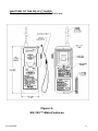
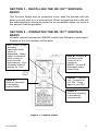
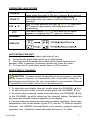
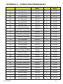
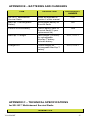
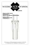
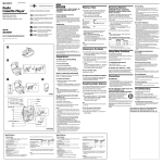
About Cobham Life Support, ACR Products
Cobham Life Support, ACR Products, www.acrelectronics.com, designs
and manufactures a complete line of safety and survival products
including EPIRBs, PLBs, AIS, SARTs, Strobe Lights, Life Jacket Lights,
Search Lights and safety accessories. The quality systems of this
facility have been registered by UL to the ISO 9001:2000 Series
Standards. Recognized as the world leader in safety and survival
technologies, ACR has provided safety equipment to the aviation and
marine industries as well as to the military since 1956.
About Cobham plc
Cobham plc is an international company engaged in the development,
delivery and support of advanced aerospace and defence systems for
land, sea, air and space, The company has four divisions that
collectively specialize in the provision of components, subsystems and
services that keep people safe, improve communications and enhance
the capability of aerospace and defence platforms.
CAUTION: Before proceeding to install, test or use your new ACR
Electronics’ product, please read this Product Support Manual in its
entirety.
If you have questions regarding the contents of the manual, please
contact our Technical Service Department at ACR Electronics, Inc.,
Telephone +1 (954) 981- 3333. Please be ready to provide the
technician with the page number you wish to discuss. If you have a
question that is not covered in the manual, please visit our website and
access the Frequently Asked Questions (FAQs) section for further
information or call our Technical Service Department. The website
address is www.acrelectronics.com. If in the future you lose this manual,
you may access and print a replacement on the ACR website.
Call Sign: ______________________________________
Vessel: ________________________________________
Battery Expiration Date: ___________________________
Table of Contents
SECTION 1 – INTRODUCTION ______________________________ 3
SECTION 2 – PREPARING TO INSTALL ________________________ 4
SECTION 3 – INSTALLING THE SR-103™ SURVIVAL RADIO ________ 6
SECTION 4 – OPERATING THE SR-103™ SURVIVAL RADIO ________ 6
SECTION 5- SENDING DISTRESS COMMUNICATIONS ____________ 9
SECTION 6 – MAINTAINING THE SR-103™ SURVIVAL RADIO ____ 10
APPENDIX A – OPERATING FREQUENCIES ____________________ 15
APPENDIX B – BATTERIES AND CHARGERS ___________________ 17
APPENDIX C – TECHNICAL SPECIFICATIONS ___________________ 17
APPENDIX D – WARRANTY, USEFUL LIFE POLICY, NOTICES _______ 18
PLEASE READ ALL WARNINGS, CAUTIONS
AND NOTES CAREFULLY
Y1-03-0128F
2
SECTION 1 – INTRODUCTION
OVERVIEW
This manual contains necessary information for the operation,
maintenance and performance of distress communications utilizing the
ACR/2727
Multichannel
Survival
Craft
Portable
Two-Way
Radiotelephone. The user is strongly recommended to read this manual
in its entirety. A photocopy of the suggested procedures for distress
communications outlined in Section 5 should be kept with each
radiotelephone to aid the designated operator and maximize the
intelligibility and success of his radio distress request.
The Multichannel Survival Craft Portable Two-Way VHF Radiotelephone
is intended to be used for on-scene emergency communications
between survival craft and ship, and survival craft and rescue units. The
radio is equipped with a 5 year lithium survival battery pack which is
user replaceable. With the lithium battery pack installed, the unit meets
all IMO, SOLAS and FCC requirements for survival craft two-way VHF
transceivers. An optional rechargeable MaxCap™ battery pack is also
available.
RADIO LICENSE REQUIREMENTS
This radio is FCC Type Accepted and GMDSS listed (FCC Part
80.1101) as a survival craft two-way VHF radiotelephone apparatus
which complies with the 1988 GMDSS SOLAS amendments. To install
the radio on a survival craft, the host ship must have a valid Ship Station
License as required by law. To obtain an application for an FCC Ship
Station License (U.S. ships), the user should contact the nearest FCC
office.
In the USA, contact the Federal Communications Commission (FCC) at
www.fcc.gov on the internet. You will need Form 605, “Quick-Form
Application for Authorization in the Ship, Aircraft, Amateur, Restricted
and Commercial Operator, and General Mobile Radio Services”, which
may be downloaded or completed online. You may also call FCC’s
Forms Distribution Center at 800-418-3676.
Please note that regulations for VHF radios may be different in different
parts of the world. Always contact your local authority to determine the
requirements that apply to you.
Y1-03-0128F
3
SECTION 2 – PREPARING TO INSTALL
ITEMS INCLUDED IN PURCHASE:
1. Multichannel Survival Radio with lithium battery, wrist
lanyard and radio cover
2. Warranty card
3. Commercial Registration Advisory
4. Product Support Manual
If any of the above is missing, please contact ACR
Electronics’
Technical
Service
by
email
at
service@acrelectronics,com or by phone at +1 (954) 9813333.
Figure 1ACR Multichannel Survival Craft Portable
Two-Way Radiotelephone
Y1-03-0128F
4
ANATOMY OF THE SR-103™ RADIO
The key components of the SR-103™ Radio are:
Figure 2SR-103™ Main Features
Y1-03-0128F
5
SECTION 3 – INSTALLING THE SR-103™ SURVIVAL
RADIO
The Survival Radio and its protective cover shall be packed with the
ship’s survival craft or in a survival suit. When not packed with a life raft,
the radiotelephone should be stored in an accessible place, as close to
the survival craft as possible.
SECTION 4 – OPERATING THE SR-103™ SURVIVAL
RADIO
All radio controls (except the ON/OFF switch) are flat-panel, push-types
located on the front surface of the radio.
PTT: Push-To-Talk
activates
transmitter while
switch is
depressed. When
switch is released,
radio returns to
receive mode
automatically. Also
refreshes channel
display for 1 sec.
VOL ▲: Volume ▲
increases audio
output level to
maximum,
VOL▼: Volume ▼
decreases audio
output level
ON/OFF: Press for
one (1) second to
turn ON. Press
again to turn OFF.
CHAN ▲:
Switches channels
in increasing
channel order
CHAN ▼:
Switches channels
in decreasing
channel order
Figure 3- Control Panel
Y1-03-0128F
6
OPERATING INDICATORS
CHAN ▲
CHAN ▼
VOL ▲ ▼
PTT
CHANNEL
The switch includes a RED light which will be illuminated when the radio is ON and Channel ▲ is selected.
The switch includes a GREEN light which will be
illuminated when the radio is ON and Channel ▼ is
selected.
Both of these switches will light up YELLOW when the
PTT switch is depressed, indicating that radio is
transmitting.
The switch blinks YELLOW at a slow rate to assist
operator in locating the PTT switch in darkness.
Indicates which channel is selected
DISPLAY
ACTIVATING THE UNIT
1. Locate slide switch on upper right side of unit.
2. Using thumb, push slide switch up to ON position.
3. Front panel will illuminate and noise will be heard coming from
speaker. After 3 seconds, automatic squelch will mute the noise.
4. To turn unit off, push slide switch down to OFF position.
SELECTING A CHANNEL
CAUTION: To assure ease of operation in an emergency, the radio
will be tuned to Channel 16 immediately after it has been turned on. In
non-emergency situations, the user must select a new channel. Channel
16 should only be used in the event of an emergency.
1. To select the next higher channel, briefly press the CHANNEL ▲ key.
2. To select the next lower channel, briefly press the CHANNEL ▼ key.
3. To select other channels, press and hold either the CHANNEL ▼ key
or the CHANNEL ▲ while observing the channel display. Release the
key when the desired channel appears on the display.
4. Certain channels used internationally for duplex operation, have been
designated in the United States by the FCC with an “A” suffix as simplex
channels. The GMDSS Survival Radio uses simplex (single-frequency)
operation only. Therefore, these channels all have an “A” suffix:
Y1-03-0128F
7
01A
02A
03A
04A
05A
07A
61A
62A
63A
64A
65A
66A
78A
79A
80A
81A
82A
83A
88A
5. The channels appear on the display in the following order:
VHF marine band channels 01A- 28
VHF marine band channels 60- 88A
VHF marine weather channels -1 through -0, display (WX1WX10)
The order is rolled over, i.e., WX10 is followed by Channel 1A.
6. The channel designators are displayed as follows:
a. Simplex only channels — the channel number remains on the
display for five (5) seconds after the CHANNEL ▲or CHANNEL ▼
key is released. The display is then blanked to conserve battery
power.
b. Simplex/duplex channels (“A” suffix) — The ACR survival radio
uses simplex mode only. After the channel has been selected, the
channel number followed by the “A” alternately flash one (1) second
each for five (5) seconds. The display is then blanked.
c. Weather channels — The display consists of a “-” followed by the
single-digit channel number. For WX10, the display shows -0. The
display is lighted for five (5) seconds after the channel is selected,
then is blanked.
7. To restore the channel display, press PTT briefly. LEDs will show
current channel number for one (1) second (simplex/duplex channels —
channel numbers for ½ second followed by an “A” for ½ second).
RECEIVING A CHANNEL AND SETTING VOLUME
1. The radio is in receive-mode as soon as a channel is selected.
Automatic squelch circuit will cause unit to be silent unless a signal is
present on the selected channel.
2. To lower the volume, press the VOLUME ▼key. Repeated pressing
of the VOLUME ▼ key will step through the volume settings until lowest
setting is reached.
3. To raise the volume, press VOLUME ▲key. Unit will be set to
maximum volume.
4. To receive very weak signals, it may be helpful to turn off the
automatic squelch. This may be done by pressing both VOLUME ▲and
VOLUME ▼simultaneously. Noise will be heard from speaker when
squelch is turned off. Pressing any key will restore the automatic
squelch.
Y1-03-0128F
8
CAUTION: Operating unit with squelch off for long periods of time
will reduce battery life.
TRANSMITTING
1. Select channel.
2. Press and hold PTT (Push To Talk) button. PTT, VOLUME ▲and
VOLUME ▼keys will illuminate.
3. Speak loudly and clearly into speaker area from a distance of
approximately 3" to 6" (7.5 to 15 cm).
4. Release PTT button to return to receive mode.
BATTERY SAVE FEATURE
To conserve battery life, the unit will automatically shut-off following a
period of approximately 20- 30 minutes of idle radio activity.
SECTION 5- SENDING DISTRESS COMMUNICATIONS
The following are a set of observations intended to help the user
maximize his success during the course of a rescue where two-way
communication is possible.
1. Transmit only when the channel is clear of activity, or between other
stations' transmissions during a distress.
2. Use the world recognized expression M'AIDER or MAYDAY to call
for help. Note that MAYDAY is commonly pronounced as it is read in
English, when utilized in English speaking countries. To improve the
chances of being understood internationally, it is best to pronounce the
above expression two ways:
a. The internationally recognized way, M'AIDER (in French)
pronounced phonetically as “mě - dě,” (see any French
language instruction book for further details) and,
b. The commonly used pronunciation in English speaking
countries MAYDAY pronounced phonetically as “mā - dā.”
To prevent the distress signal from being misunderstood, and to
improve the intelligibility of the distress call, use the two pronunciations
above when calling, for example (also, see example for part c):
“M’AIDER MAYDAY M’AIDER THIS IS MARY JANE WXT599
WXT599 WXT599”.
3. Always use the ICAO Convention (Convention on International Civil
Aviation) recognized alphabet for spelling.
Y1-03-0128F
9
ICAO recognized alphabet:
A
B
C
D
E
F
G
H
I
J
K
L
M
Alpha
Bravo
Charlie
Delta
Echo
Foxtrot
Golf
Hotel
India
Juliet
Kilo
Lima
Mike
N
O
P
Q
R
S
T
U
V
W
X
Y
Z
November
Oscar
Papa
Quebec
Romeo
Sierra
Tango
Uniform
Victor
Whiskey
X-ray
Yankee
Zulu
EXAMPLE: “M’AIDER MAYDAY M’AIDER THIS IS MARY JANE
Whiskey X-ray Tango 599 Whiskey X-ray Tango 599 Whiskey X-ray
Tango 599”
To acknowledge that a transmission has been received and understood
in its entirety, simply use the expression “R R R” spoken as “Romeo
Romeo Romeo” (“R” stands for received). Note: some radio operators
use the expression “Roger” instead of “Romeo”.
4. Antenna height and range of communications are intimately related.
In general, a higher antenna will have a longer range than a similar
lower antenna.
The typical range for a transmitting radio held at about 1.2 meters (4.0
ft) above average water level is expected to equal 4.5 kilometers (2.8
statute miles). The receiving shipborne antenna can extend the range if
it is mounted high. Airborne receivers greatly extend the above range
(over 150 kilometers/100 miles for aircraft flying over 1500 meters/5000
ft).
Because of the above fact, and to maximize the range of the survival
craft VHF radiotelephone, the unit should be held as high as possible
without endangering the safety of the operator.
SECTION 6 – MAINTAINING THE SR-103™ SURVIVAL
RADIO
MANDATORY TESTING
Radiotelephones operated within the U.S.A. must be operationally
tested on a periodic basis (FCC regulations, Part 80, section 80.834,
until superseded by section 80.1095).
Y1-03-0128F
10
To test the radiotelephone, follow the steps given below.
NOTE: This test requires that a separate VHF marine radio transceiver
be used to monitor transmitted and received signals.
Any transmissions effected for the purpose of testing the Survival Radio
shall be as brief as possible. The recommended test
message format is as follows: “<name of station
receiving the test message> THIS IS <name of
station transmitting this text><station call
sign or call letters>”. EXAMPLE: “BLUE
DUCK THIS IS MARY JANE WXT599”.
When a second radiotelephone or the
ship's receiver is utilized to monitor
proper operation of the Survival Radio,
the test distance between devices
should be kept to a maximum and the
following message format should be
observed:
“<name
of
station
transmitting this text> THIS IS <name
of station transmitting this text>
MOBILE 1”. EXAMPLE: “MARY JANE
THIS IS MARY JANE MOBILE 1
WXT599”
NOTE: If the unit to be tested is not on
board the vessel containing the fixed
station, “UNIT 1” should be used rather
than “MOBILE 1”.
1. Remove the radio from its survival
craft package.
2. Remove control panel protective
cover.
3. Slide ON/OFF switch up to ON
Figure 4- Protective Cover
position.
4. Listen for the tone and for the squelch action 3 seconds after
activating the unit.
5. The receiver tunes to Channel 16 automatically when unit is turned
ON.
6. Listen for any activity on the frequency (channel 16).
7. If no activity is detected, transmit the test message and have
someone monitor the transmission (see above for suggested test
message formats).
Y1-03-0128F
11
8. If the test signal was not heard (full quieting), replace the battery
and retest. If the test signal is still not heard (full quieting), have the unit
inspected at your nearest authorized service center.
9. Have someone return the call from the monitoring station (lowest
power setting) to verify proper radiotelephone receiver operation.
10. If a response is not heard (full quieting), have the radio unit
inspected at your nearest authorized service center.
11. Press the CHAN ▼ key to tune unit to any channel (except
Channel 16).
12. Set the monitoring transceiver to the same frequency (see
Appendix for operating frequencies).
13. Listen for any activity.
14. If no activity is detected, transmit the test message and have
someone monitor the transmission (see above for suggested test
message formats).
15. If the test signal was not heard (full quieting), have the unit
inspected at your nearest authorized service center.
16. Have someone return the call from the monitoring station (lowest
power setting) to verify proper radiotelephone receiver operation.
17. If a response is not heard (full quieting), have the radio unit
inspected at your nearest authorized service center.
18. Slide ON/OFF button to turn unit OFF.
19. Replace control panel protective cover.
20. Replace unit into its survival craft package.
VISUAL INSPECTION
Periodically inspect the Survival Radio for damage, cracks and front
panel label wear. Wipe off any salt deposits with a damp cloth.
Y1-03-0128F
12
BATTERY INFORMATION
Figure 5- Battery Installation
Battery options
Lithium Survival Battery (Product No. 1066)
The Survival Radio is supplied with a replaceable lithium battery pack.
This primary battery pack will operate the radio for at least 8 hours, in
compliance with IMO/SOLAS and FCC requirements for a survival craft
radio. To maintain compliance with these regulations, the lithium battery
pack must be replaced after 5 years or after any use (with the exception
of activating the unit for the purpose of testing.)
Additional lithium battery packs may be stored in survival craft along
with the radio for extended operating life.
CAUTION: The battery is internally fused to avoid fire hazard. Do
not immerse in water, short circuit or incinerate.
Y1-03-0128F
13
MaxCap™ Rechargeable (Ni-Cad) Battery (Product No. 1067)
To allow the survival radio to be used in non-emergency situations, a
rechargeable battery pack (ACR Product No. 1067), and a MaxCap™
Charger (ACR Product No. 2711) are also available. The rechargeable
battery pack will operate the unit for approximately four to six hours. The
charger is capable of charging the battery in less than 135 minutes.
Refer to charger manual for charging instructions.
CAUTION: When the radio is operating with the rechargeable
battery pack, it does not comply with the SOLAS/GMDSS regulation for
battery life.
How to replace the battery pack
Lift the battery handle, turn it counter-clockwise until it stops and pull the
battery out. Replace a fresh battery into the rear of the radio. Turn the
handle clockwise until it stops and snap it down to lock into position.
Make sure battery is engaged by turning the unit ON and then OFF.
Y1-03-0128F
14
APPENDIX A – OPERATING FREQUENCIES
CHANNEL
DESCRIPTION
TRANSMIT
(MHz)
MODE
RECEIVE
(MHz)
01A
Port Operations
156.050
S
156.050
02A
Port Operations
156.100
S
156.100
03A
Port Operations
156.150
S
156.150
04A
Port Operations
156.200
S
156.200
05A
Port Operations
156.250
S
156.250
06
Intership Safety
156.300
S
156.300
07A
Commercial, Intership
156.350
S
156.350
08
Commercial, Intership
156.400
S
156.400
09
Com’l/Non-Commercial
156.450
S
156.450
10
Commercial, Intership
156.500
S
156.500
11
Commercial, Intership
156.550
S
156.550
12
Port Operations
156.600
S
156.600
13
Bridge to Bridge
156.650
S
156.650
14
Port Operations
156.700
S
156.700
15
Environmental
156.750
S
156.750
16
Distress, Safety & Calling
156.800
S
156.800
17
Maritime Control
156.850
S
156.850
18A
Commercial, Intership
156.900
S
156.900
19A
Commercial, Intership
156.950
S
156.950
08
Commercial, Intership
156.400
S
156.400
09
Com’l/Non-Commercial
156.450
S
156.450
10
Commercial, Intership
156.500
S
156.500
11
Commercial, Intership
156.550
S
156.550
12
Port Operations
156.600
S
156.600
13
Bridge to Bridge
156.650
S
156.650
14
Port Operations
156.700
S
156.700
15
Environmental
156.750
S
156.750
Y1-03-0128F
15
16
Distress, Safety & Calling
156.800
S
156.800
65A
Port Operations
156.275
S
156.275
66A
Port Operations
156.325
S
156.325
67
Bridge-to-Bridge
156.375
S
156.375
68
Non-Commercial
156.425
S
156.425
69
Non-Commercial
156.475
S
156.475
71
Non-Commercial
156.575
S
156.575
72
Non-Commercial
156.625
S
156.625
73
Port Operations
156.675
S
156.675
74
Port Operations
156.725
S
156.725
75
Guardband (Rec. only)
---------
R
156.775
76
Guardband (Rec. only)
---------
R
156.825
77
Intership, Port Operations
156.875
S
156.875
78A
Non-Commercial
156.925
S
156.925
79A
Commercial, Intership
156.975
S
156.975
80A
Commercial, Intership
157.025
S
157.025
81A
U.S. Government Only
157.075
S
157.075
82A
U.S. Government Only
157.125
S
157.125
83A
U.S. Government Only
157.175
S
157.175
88A
Commercial, Intership
157.425
S
157.425
WX1
Weather (Receive Only) — NOAA
162.550
WX2
Weather (Receive Only) — NOAA
162.400
WX3
Weather (Receive Only) — NOAA
162.475
WX4
Weather (Receive Only) — CANADA
162.425
WX5
Weather (Receive Only)
162.450
WX6
Weather (Receive Only)
162.500
WX7
Weather (Receive Only) — CANADA
162.525
WX8
Weather (Receive Only) — ENVIRONMENTAL
161.650
WX9
Weather (Receive Only)
161.775
WX10
Weather (Receive Only)
163.275
Y1-03-0128F
16
APPENDIX B – BATTERIES AND CHARGERS
ITEM
DESCRIPTION
ACR PRODUCT
NUMBER
SR-103™ Multichannel
Survival Radio
Radio as described in
Section 2 of this manual
2727
MaxCap™ Rechargeable
Battery
Rechrgeable battery for
Survival Radio
1067
Lithium Survival Battery
Lithium battery pack for
Survival Radio (5-year
replacement life)
1066
MaxCap™ Charger
Fast charger (<3 hours)
for rechargeable
MaxCap™ battery.
Includes battery.
2711, 2711.1
Charger XLT
Trickle charger for
rechargeable MaxCap™
battery.
2713, 2713.1
APPENDIX C – TECHNICAL SPECIFICATIONS
for SR-103™ Multichannel Survival Radio
TRANSMITTER
Y1-03-0128F
17
Power output (ERP)
500mW ± 2.5dB
Frequency control
Quartz crystal (±.001%)
Modulation type
Phase
Max. modulation
± 5kHz
Audio width
300/2500Hz
RECEIVER
Sensitivity (12dB SINAD)
1.0 µV
Audio output
300mW
BATTERY
Type
Primary: lithium
Storage life
10 years
Operating life under
typical duty of 1:9 (i.e., 6
sec Tx, 6 sec Rx, 48 sec
stand by)
8 hours @ -20°C
SERVICE CONDITIONS
Temperature
-20°C to +50°C
Altitude
0 to 40,000ft/ 0 to 12000m
Water resistance
3m depth, max up to 5 minutes
DIMENSIONS (less antenna)
Height
7.6in/ 19.3cm
Width
2.6in/ 6.6cm
Thickness
1.7in/ 4.3cm
Antenna
11.5in/ 29.2cm
Weight (includes battery)
1.0lb/ 0.46kg
APPENDIX D – WARRANTY, USEFUL LIFE POLICY,
NOTICES
LIMITED WARRANTY
This product is warranted against factory defects in material and workmanship for a
period of 1 (one) year* from date of purchase or receipt as a gift. During the warranty
period ACR Electronics, Inc. will repair or, at its option, replace the unit at no cost to
you for labor, materials and return transportation from ACR. For further assistance,
please contact our Technical Service Department at ACR Electronics, Inc.,5757
Ravenswood
Road,
Fort
Lauderdale,
FL
33312-6645.
Email:
Y1-03-0128F
18
[email protected], Fax: +1 (954) 983-5087, Telephone: +1 (954) 9813333.
This warranty does not apply if the product has been damaged by accident or
misuse, or as a result of service or modification performed by an unauthorized
factory. Except as otherwise expressly stated in the previous paragraph, THE
COMPANY MAKES NO REPRESENTATION OR WARRANTY OF ANY KIND,
EXPRESS OR IMPLIED, AS TO MERCHANTABILITY, FITNESS FOR A
PARTICULAR PURPOSE, OR ANY OTHER MATTER WITH RESPECT TO THIS
PRODUCT. The Company shall not be liable for consequential or special damages.
To place the warranty in effect, register online at www.acrelectronics.com or return
the attached card within 10 days.
*Five years for the following products: EPIRB, PLB, S-VDR, SSAS.
USEFUL LIFE POLICY
The typical service life of a properly maintained Product is limited to 12 years from
date of manufacture. Products that are 12 years and 1 month or older from date of
manufacture will not be serviced by ACR or our Battery Replacement Centers. A
Product that is 12 or less years old from date of manufacture will be serviced as long
as the unit appears fit to be placed back into its final operational cycle. Service
includes the replacement of those items that must be replaced at service intervals
and the verification that the device appears to be in good mechanical and electrical
working condition by an ACR authorized service technician.
NOTICES
ACR Electronics diligently works to provide a high quality Product Support Manual,
however, despite best efforts, information is subject to change without notice, and
omissions and inaccuracies are possible. ACR cannot accept liability for manual
contents. To ensure that you have the most recent version of the Product Support
Manual, please visit the ACR website at www.acrelectronics.com.
©2009 by ACR Electronics, Inc., part of Cobham plc. All rights reserved.
Reproduction in whole or in part is permitted only with permission of ACR
Electronics, Inc.
___________________________________________________________________
Ongoing product improvements may change product specifications without notice.
Trademarks or registered trademarks are the property of their respective owners.
Y1-03-0128F
19