1
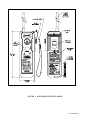
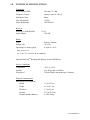
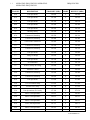
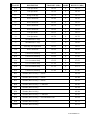
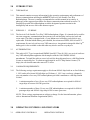
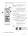
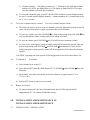
PRODUCT
SUPPORT
MANUAL
Y1-03-0128
Rev. E
SR-103
Product No. 2727
GMDSS Survival Radio
This radio meets GMDSS requirements only when used
with ACR's Lithium Battery Product No. 1066. The
performance specifications listed in this manual are
based on the 1066 Lithium Battery as the power source.
ACR Electronics, Inc.
5757 Ravenswood Road
Fort Lauderdale, Fl 33312
+1(954) 981-3333 · Fax +1 (954) 983-5087
www.acrelectronics.com
Email: [email protected]
A Chelton Group company
TABLE OF CONTENTS
FIGURE 1: ACR/GMDSS SURVIVAL RADIO...............................................................................1
1.0
TECHNICAL SPECIFICATIONS.......................................................................................2
1.1
Operating Frequencies ......................................................................................... 3-4
2.0
INTRODUCTION................................................................................................................5
2.1
This Manual .............................................................................................................5
2.2
Purpose.....................................................................................................................5
2.3
Authorization ..........................................................................................................5
2.4
Carriage Requirements.............................................................................................5
3.0
OPERATING CONTROLS AND INDICATORS ..............................................................6
3.1
Operating Controls...................................................................................................6
3.2
Operating Indicators.................................................................................................6
FIGURE 2: ACR/GMDSS SURVIVAL RADIO CONTROL PANEL...................................6
4.0
OPERATION ................................................................................................................... 7-8
4.1
To Activate the Unit.................................................................................................7
4.2
To Select a Channel .................................................................................................7
4.3
To Receive a Channel and Set Volume ...................................................................8
4.4
To Transmit..............................................................................................................8
4.5
Battery Save Feature ................................................................................................8
5.0
INSTALLATION AND MAINTENANCE ................................................................... 9-11
5.1
Installation................................................................................................................9
5.2
Mandatory Testing ...................................................................................................9
5.3
Visual Inspection....................................................................................................10
FIGURE 3: CONTROL PANEL PROTECTIVE COVER .................................................11
6.0
BATTERY INFORMATION ...................................................................................... 12-13
FIGURE 4: BATTERY REPLACEMENT .........................................................................12
6.1
Battery Options ......................................................................................................13
6.1.1 Lithium Survival Battery (Product No. 1066)............................................13
6.1.2 MaxCap Rechargeable (Ni-Cad) Battery (Product No. 1067) ...................13
6.2
How to Replace the Battery Pack...........................................................................13
7.0
DISTRESS COMMUNICATIONS ............................................................................. 13-15
i
FIGURE 1: ACR/GMDSS SURVIVAL RADIO
Y1-03-0128 Rev. E
1.0
TECHNICAL SPECIFICATIONS
Transmitter
Power Output (ERP)
500 mW ± 2.5 dB
Frequency Control
Quartz Crystal (± .001%)
Modulation Type
Phase
Max. Modulation
±5 kHz
Audio Bandwidth
300/2500 Hz
Receiver
Sensitivity (12dB SINAD)
Audio Output
1.0 µV
300 mW
Battery
Type
Primary, Lithium
Storage Life
10 Years
Operating Life under typical
8 hours @ -20°C
duty cycle of 1:9
(i.e., 6 sec Tx, 6 sec Rx, 48 sec stand by)
Optional MaxCapTM Rechargeable Battery for non-GMDSS use.
Service Conditions
Temperature
-20°C to +50°C
Altitude
0 to 40,000 ft/0 to 12000 m
Waterproof
3 Meter Depth, maximum up to 5 minutes
Physical Characteristics
Dimensions (Less Antenna)
Height
7.6 in/19.3 cm
Width
2.6 in/ 6.6 cm
Thickness
1.7 in/4.3 cm
Antenna
11.5 in/29.2 cm
Weight (includes Battery)
1.0 lb/0.46 kg
Y1-03-0128 Rev. E
1.1
OPERATING FREQUENCIES.1 OPERATING
OPERATING FREQUENCIES
FREQUENCIES.1
CHANNEL
DESCRIPTION
TRANSMIT (MHz)
MODE
RECEIVE (MHz)
01A
Port Operations
156.050
S
156.050
02A
Port Operations
156.100
S
156.100
03A
Port Operations
156.150
S
156.150
04A
Port Operations
156.200
S
156.200
05A
Port Operations
156.250
S
156.250
06
Intership Safety
156.300
S
156.300
07A
Commercial, Intership
156.350
S
156.350
08
Commercial, Intership
156.400
S
156.400
09
Com’l/Non-Commercial
156.450
S
156.450
10
Commercial, Intership
156.500
S
156.500
11
Commercial, Intership
156.550
S
156.550
12
Port Operations
156.600
S
156.600
13
Bridge to Bridge
156.650
S
156.650
14
Port Operations
156.700
S
156.700
15
Environmental
156.750
S
156.750
16
Distress, Safety & Calling
156.800
S
156.800
17
Maritime Control
156.850
S
156.850
18A
Commercial, Intership
156.900
S
156.900
19A
Commercial, Intership
156.950
S
156.950
20A
Port Operations
157.000
S
157.000
21A
U.S. Government Only
157.050
S
157.050
22A
Liaison USCG Only
157.100
S
157.100
23A
Port Operations, Gov’t only
157.150
S
157.150
60
Public Correspondence
156.025
S
156.025
61A
Public Correspondence
156.075
S
156.075
62A
Public Correspondence
156.125
S
156.125
63A
Com’l, Port Operations
156.175
S
156.175
64A
Public Correspondence
156.225
S
156.225
Y1-03-0128 Rev. E
CHANNEL
DESCRIPTION
TRANSMIT (MHz)
MODE
RECEIVE (MHz)
65A
Port Operations
156.275
S
156.275
66A
Port Operations
156.325
S
156.325
67
Bridge-to-Bridge
156.375
S
156.375
68
Non-Commercial
156.425
S
156.425
69
Non-Commercial
156.475
S
156.475
71
Non-Commercial
156.575
S
156.575
72
Non-Commercial
156.625
S
156.625
73
Port Operations
156.675
S
156.675
74
Port Operations
156.725
S
156.725
75
Guardband (Rec. only)
---------
R
156.775
76
Guardband (Rec. only)
---------
R
156.825
77
Intership, Port Operations
156.875
S
156.875
78A
Non-Commercial
156.925
S
156.925
79A
Commercial, Intership
156.975
S
156.975
80A
Commercial, Intership
157.025
S
157.025
81A
U.S. Government Only
157.075
S
157.075
82A
U.S. Government Only
157.125
S
157.125
83A
U.S. Government Only
157.175
S
157.175
88A
Commercial, Intership
157.425
S
157.425
WX1
Weather (Receive Only) — NOAA
162.550
WX2
Weather (Receive Only) — NOAA
162.400
WX3
Weather (Receive Only) — NOAA
162.475
WX4
Weather (Receive Only) — CANADA
162.425
WX5
Weather (Receive Only)
162.450
WX6
Weather (Receive Only)
162.500
WX7
Weather (Receive Only) — CANADA
162.525
WX8
Weather (Receive Only) — ENVIRONMENTAL
161.650
WX9
Weather (Receive Only)
161.775
WX10
Weather (Receive Only)
163.275
Y1-03-0128 Rev. E
2.0
INTRODUCTION
2.1
THIS MANUAL
2.1.1
This manual contains necessary information for the operation, maintenance and performance of
distress communications utilizing the ACR/2727 Survival Craft Portable Two-Way
Radiotelephone. The user is strongly recommended to read this manual in its entirety. A
photocopy of the suggested procedures for distress communications outlined in section 7.0
should be kept with each radiotelephone to aid the designated operator maximize the
intelligibility and success of his radio distress request.
2.2
PURPOSE .2
2.2.1
The Survival Craft Portable Two-Way VHF Radiotelephone (Figure 1) is intended to be used for
on-scene emergency communications between survival craft and ship, and survival craft and
rescue units. The radio is equipped with a 5 year lithium survival battery pack which is user
replaceable. With the lithium battery pack installed, the unit meets all IMO, SOLAS and FCC
requirements for survival craft two-way VHF transceivers. An optional rechargeable MaxCapTM
battery pack is also available so that the radio may also be used for everyday use.
2.3
AUTHORIZATION
2.3.1
This radio is FCC Type Accepted and GMDSS listed (FCC Part 80.1101) as a survival craft twoway VHF radiotelephone apparatus which complies with the 1988 GMDSS SOLAS
amendments. To install the radio on a survival craft, the host ship must have a valid Ship Station
License as required by law. To obtain an application for an FCC Ship Station License (U.S.
ships), the user should contact the nearest FCC office.
2.4
CARRIAGE REQUIREMENTS
2.4.1
The following carriage requirements apply to all relevant SOLAS ships built on or after February
1, 1992, and to all relevant SOLAS ships as of February 1, 1995. Any vessel may voluntarily
carry any number of two-way VHF radiotelephones provided it maintains a valid Ship Station
License:
PURPOSE
1.
A minimum number of two (2) two-way VHF radiotelephones are required for SOLAS
cargo ships of between 300-500 gross tons.
2.
A minimum number of three (3) two-way VHF radiotelephones are required for SOLAS
passenger ships and SOLAS cargo ships of 500 or more gross tons.
NOTE: These carriage requirements are subject to change. For the latest information, please
refer to International Maritime Organization (IMO).
3.0
OPERATING CONTROLS AND INDICATORS
3.1
OPERATING CONTROLS .1
OPERATING CONTROLS
All controls (except the ON/OFF switch) are flat panel push types located on the front surface of
the radio (see Figure 2, Control Panel).
ON/OFF
Slide up to turn ON, and slide down to turn OFF.
VOLUME s
Increases audio output level to maximum.
VOLUME t
Decreases audio output level.
PTT
Push To Talk activates transmitter while switch
is depressed. When switch is released, radio
returns to receive mode automatically. (Also
refreshes channel display for 1 second.)
CHANNEL s
Switches channels in increasing channel order.
CHANNEL t
Switches channels in decreasing channel order.
3.2 OPERATING INDICATORS
.2
OPERATING INDICATORS.2 OPERATING INDICATORS
CHANNEL s
This switch includes a RED light which will be
illuminated when the radio is ON and the
Channel s is selected.
CHANNEL t
This switch includes a GREEN light which will be
illuminated when the radio is ON and Channel t
is selected.
VOLUME s t Both of these switches will light up YELLOW
when the Push To Talk switch is depressed,
indicating that the radio is transmitting.
PTT
This switch blinks YELLOW at a slow rate to
assist operator in locating the PTT (Push To
Talk) switch in darkness.
CHANNEL
Indicates which channel is selected.
Figure 2: GMDSS Survival
Radio Control Panel
DISPLAY
4.0
OPERATION .0 OPERATION
Y1-03-0128 Rev. E
4.1
To activate the unit.1 To activate the unit:
a)
b)
c)
d)
4.2
Locate slide switch on upper right side of unit (Figure 1).
Using thumb, push slide switch up to ON position.
Front panel will illuminate and noise will be heard coming from speaker. After 3
seconds, automatic squelch will mute the noise.
To turn unit off, push slide switch down to OFF position.
To select a channel.2 To select a channel:
CAUTION: To assure ease of operation in an emergency, the radio will be tuned to
Channel 16 immediately after it has been turned on. In non-emergency situations, the user
must select a new channel. Channel 16 should only be used in the event of an emergency.
a) To select the next higher channel, briefly press the CHANNEL s key.
b) To select the next lower channel, briefly press the CHANNEL t key.
c) To select other channels, press and hold either the CHANNEL s key or the
CHANNEL t while observing the channel display. Release the key when the
desired channel appears on the display.
d)
Certain channels used internationally for duplex operation, have been designated in
the United States by the FCC with an “A” suffix as simplex channels. The GMDSS
Survival Radio uses simplex (single-frequency) operation only. Therefore, these
channels all have an “A” suffix:
01A
02A
03A
e)
04A
05A
07A
61A
62A
63A
64A
65A
66A
78A
79A
80A
81A
82A
83A
88A
The channels appear on the display in the following order:
VHF marine band channels 01A — 28
VHF marine band channels 60 — 88A
VHF marine weather channels -1 through -0, display (WX1 — WX10)
The order is rolled over, i.e., WX10 is followed by Channel 1A.
f)
The channel designators are displayed as follows:
1) Simplex only channels — the channel number remains on the display for five
(5) seconds after the CHANNEL s or CHANNEL t key is released. The
display is then blanked to conserve battery power.
2) Simplex/duplex channels (“A” suffix) — The ACR survival radio uses simplex mode
only. After the channel has been selected, the channel number followed by the “A”
alternately flash one (1) second each for five (5) seconds. The display is then blanked.
Y1-03-0128 Rev. E
3) Weather channels — The display consists of a “-” followed by the single-digit channel
number. For WX10, the display shows -0. The display is lighted for five (5) seconds
after the channel is selected, then is blanked.
g) To restore the channel display, press PTT briefly. LEDs will show current channel number
for one (1) second (simplex/duplex channels — channel numbers for ½ second followed by
an “A” for ½ second).
4.3
To receive a channel and set volume.3 To receive a channel and set volume:
a)
The radio is in receive mode as soon as a channel is selected. Automatic squelch circuit will
cause unit to be silent unless a signal is present on the selected channel.
b) To lower the volume, press the VOLUME tkey. Repeated pressing of the VOLUME t key
will step through the volume settings until lowest setting is reached.
c)
To raise the volume, press VOLUME s key. Unit will be set to maximum volume.
d) To receive very weak signals, it may be helpful to turn off the automatic squelch. This may
be done by pressing both VOLUME s and VOLUME t simultaneously. Noise will be
heard from speaker when squelch is turned off. Pressing any key will restore the automatic
squelch.
CAUTION: Operating unit with squelch off for long periods of time will reduce battery life.
4.4
To transmit.4
a)
To transmit:
Select channel as in section 3.2.
b) Press and hold PTT (Push To Talk) button. PTT, VOLUME s and VOLUME t keys will
illuminate.
c)
Speak loudly and clearly into speaker area from a distance of approximately 3" to 6"
(7.5 to 15 cm).
d) Release PTT button to return to receive mode.
4.5
Battery save feature
a)
To conserve battery life, the unit will automatically shut-off following a period of
approximately 20 – 30 minutes of idle radio activity
5.0
INSTALLATION AND MAINTENANCE 5.0
INSTALLATION AND MAINTENANCE
5.1
INSTALLATION .1 INSTALLATION
Y1-03-0128 Rev. E
The Survival Radio and its protective cover shall be packed with the ship's survival craft
or in a survival suit. When not packed with a life raft, the radiotelephone should be
stored in an accessible place, as close to the survival craft as possible.
5.2
MANDATORY TESTING .2
MANDATORY TESTING
5.2.1
Radiotelephones operated within the U.S.A. must be operationally tested on a periodic
basis (FCC regulations, part 80, section 80.834, until superseded by section 80.1095). To
test the radiotelephone, follow the steps given below (Note: this test requires that a
separate VHF marine radio transceiver be used to monitor transmitted and received
signals). Any transmissions effected for the purpose of testing the Survival Radio shall be
as brief as possible. The recommended test message format is as follows: “<name of
station receiving the test message> THIS IS <name of station transmitting this
text><station callsign or call letters>.” EXAMPLE: “BLUE DUCK THIS IS MARY
JANE WXT599.” When a second radiotelephone or the ship's receiver is utilized to
monitor proper operation of the Survival Radio, the test distance between devices should
be kept to a maximum and the following message format should be observed: “<name of
station transmitting this text> THIS IS <name of station transmitting this text>
MOBILE 1.” EXAMPLE: “MARY JANE THIS IS MARY JANE MOBILE 1 WXT599”
(NOTE: if the unit to be tested is not on board the vessel containing the fixed station,
“UNIT 1” should be used rather than “MOBILE 1”.)
a.
Remove the radio from its survival craft package.
b.
Remove control panel protective cover.
c.
Slide ON/OFF switch up to “ON” position.
d.
Listen for the tone and for the squelch action 3 seconds after activating the unit.
e.
The receiver tunes to Channel 16 automatically when unit is turned ON.
f.
Listen for any activity on the frequency (Channel 16).
g.
If no activity is detected, transmit the test message and have someone monitor the
transmission (see above for suggested test message formats).
h.
If the test signal was not heard (full quieting), replace the battery and retest. If the
test signal is still not heard (full quieting), have the unit inspected at your nearest
authorized service center.
i.
Have someone return the call from the monitoring station (lowest power setting) to
verify proper radiotelephone receiver operation.
j.
If a response is not heard (full quieting), have the radio unit inspected at your nearest
authorized service center.
Y1-03-0128 Rev. E
k.
Press the CHANNEL t key to tune unit to any channel (except Channel 16).
l.
Set the monitoring transceiver to the same frequency. (See Table 4.1 for operating
frequencies.)
m. Listen for any activity.
n.
If no activity is detected, transmit the test message and have someone monitor the
transmission (see above for suggested test message formats.)
o.
If the test signal was not heard (full quieting), have the unit inspected at your nearest
authorized service center.
p.
Have someone return the call from the monitoring station (lowest power setting) to
verify proper radiotelephone receiver operation.
q.
If a response is not heard (full quieting), have the radio unit inspected at your nearest
authorized service center.
r.
Slide ON/OFF switch to “OFF” position.
s.
Replace control panel protective cover.
t.
Replace unit into its survival craft package.
5.3
VISUAL INSPECTION .3
VISUAL INSPECTION
5.3.1
Periodically inspect the Survival Radio for damage, cracks and front panel label wear.
Wipe off any salt deposits with a damp cloth.
Y1-03-0128 Rev. E
FIGURE 3: CONTROL PANEL PROTECTIVE COVER
6.0
BATTERY INFORMATION
Y1-03-0128 Rev. E
FIGURE 4: BATTERY REPLACEMENT
FIGURE 4 BATTERY REPLACEMENT6.1
6.1.1
Battery Options.
Lithium Survival Battery (Product No. 1066)
Y1-03-0128 Rev. E
The Survival Radio is supplied with a replaceable lithium battery pack. This
primary battery pack will operate the radio for at least 8 hours, in compliance
with IMO/SOLAS and FCC requirements for a survival craft radio. To maintain
compliance with these regulations, the lithium battery pack must be replaced after
5 years or after any use (with the exception of activating the unit for the purpose
of testing.)
Additional lithium battery packs may be stored in survival craft along with the
radio for extended operating life.
CAUTION: The battery is internally fused to avoid fire hazard. Do not immerse
in water, short circuit or incinerate.
6.1.2
MaxCapTM Rechargeable (Ni-Cad) Battery (Product No. 1067)
To allow the survival radio to be used in non-emergency situations, a
rechargeable battery pack (ACR Product No. 1067), and a MaxCapTM Charger
(ACR Product No. 2711) are also available. The rechargeable battery pack will
operate the unit for approximately four to six hours. The charger is capable of
charging the battery in less than 135 minutes. Refer to charger manual for
charging instructions.
CAUTION: When the radio is operating with the rechargeable battery pack, it
does not comply with the SOLAS/GMDSS regulation for battery life.
6.2
How to replace the battery pack: (Refer to Figure 4)
Simply lift the battery handle, turn it counter-clockwise until it stops and pull the
battery out. Replace a fresh battery into the rear of the radio. Turn the handle
clockwise until it stops and snap it down to lock into position. Make sure battery
is engaged by turning the unit ON and then OFF.
7.0
DISTRESS COMMUNICATIONS
7.1
The following are a set of observations intended to help the user maximize his success
during the course of a rescue where two-way communication is possible:
a.
Transmit only when the channel is clear of activity, or between other stations'
transmissions during a distress.
b.
Use the world recognized expression M'AIDER or MAYDAY to call for help. Note
that MAYDAY is commonly pronounced as it is read in English, when utilized in
English speaking countries. To improve the chances of being understood
internationally, it is best to pronounce the above expression two ways:
1.
The internationally recognized way, M'AIDER (in French) pronounced
(
(
phonetically as “ me - d e ” (see any French language instruction book for
further details) and,
Y1-03-0128 Rev. E
2.
The commonly used pronunciation in English speaking countries MAYDAY
pronounced phonetically as “ ma - d a . ”
To prevent the distress signal from being misunderstood, and to improve
the intelligibility of the distress call, use the two pronunciations above
when calling, for example (also, see example for part c): “M’AIDER
MAYDAY M’AIDER THIS IS MARY JANE WXT599 WXT599 WXT599.”
c.
Always use the ICAO Convention (Convention on International Civil
Aviation) recognized alphabet for spelling.
ICAO recognized alphabet:
A
B
C
D
E
F
G
H
I
J
K
L
M
Alpha
Bravo
Charlie
Delta
Echo
Foxtrot
Golf
Hotel
India
Juliet
Kilo
Lima
Mike
N
O
P
Q
R
S
T
U
V
W
X
Y
Z
November
Oscar
Papa
Quebec
Romeo
Sierra
Tango
Uniform
Victor
Whiskey
X-ray
Yankee
Zulu
Example: “M’AIDER MAYDAY M’AIDER THIS IS MARY JANE Whiskey Xray Tango 599 Whiskey X-ray Tango 599 Whiskey X-ray Tango
599”
To acknowledge that a transmission has been received and understood in its
entirety, simply use the expression “R R R” spoken as “Romeo Romeo
Romeo” (“R” stands for received). Note: some radio operators use the
expression “Roger” instead of “Romeo.”
d.
Antenna height and range of communications are intimately related. In
general, a higher antenna will have a longer range than a similar lower
antenna.
The typical range for a transmitting radio held at about 1.2 meters (4.0 ft)
above average water level is expected to equal 4.5 kilometers (2.8 statute
miles). The receiving shipborne antenna can extend the range if it is mounted
high. Airborne receivers greatly extend the above range (over 150
kilometers/100 miles for aircraft flying over 1500 meters/5000 ft).
Y1-03-0128 Rev. E
Because of the above fact, and to maximize the range of the survival craft
VHF radiotelephone, the unit should be held as high as possible without
endangering the safety of the operator.
COMMENTS (NOTES):
CALL SIGN: __________________________________________________________________
VESSEL: _____________________________________________________________________
BATTERY EXPIRATION DATE:
________________________________________________
Y1-03-0128 Rev. E