1
LBI-39101
INSTALLATION AND SET-UP MANUAL
C3 MAESTRO™ CONSOLE SYSTEM
WITH ENHANCED AUDIO ENCLOSURE
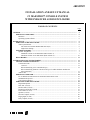
TABLE OF CONTENTS
Page
GENERAL ................................................................................................................................................
PERSONAL COMPUTERS ..............................................................................................................
Hardware ......................................................................................................................................
Operating System Software ...........................................................................................................
5
6
6
6
BOARD SET-UP....................................................................................................................................... 6
ENHANCED AUDIO ENCLOSURE ................................................................................................ 6
Audio System Board...................................................................................................................... 6
Mic Audio ALC Enable/Disable DIP Switch (S1)................................................................... 6
Digital Pots Settings ............................................................................................................... 7
SPEAKER ASSEMBLY .................................................................................................................... 7
Speaker Amp Board ...................................................................................................................... 7
Minimum Volume Level DIP Switch (SW1 Position 1) .......................................................... 7
Maximum Volume Level DIP Switch (SW1 Position 2).......................................................... 10
RS-422 BOARD.................................................................................................................................. 11
INTERCONNECTING THE EQUIPMENT ...........................................................................................
CEC/IMC INTERCONNECTIONS..................................................................................................
Control Data Link .........................................................................................................................
Overview................................................................................................................................
RS-422 Interfacing (Co-Located Hook-Ups) ...........................................................................
RS-232 Interfacing (Remote Console Hook-Ups Via 4-Wire Modems And RS-232
Interconnections)....................................................................................................................
Audio Links ..................................................................................................................................
PERSONAL COMPUTER ................................................................................................................
PC-To-Enhanced Audio Enclosure Serial Data Interconnect Cable................................................
Standard PC Keyboard ..................................................................................................................
Video Display Monitor..................................................................................................................
ENHANCED AUDIO ENCLOSURE ................................................................................................
Dispatch Keyboard ........................................................................................................................
Desk Mic (if used)........................................................................................................................
Headset Jacks (if used) ..................................................................................................................
Boom/Gooseneck Mic (if used)......................................................................................................
Footswitches (if used)....................................................................................................................
Speakers (if used)..........................................................................................................................
Recorder Outputs (if used).............................................................................................................
Paging Input (if used)....................................................................................................................
Relay Outputs (if used)..................................................................................................................
ericssonz
11
11
12
12
12
13
14
18
18
18
18
18
18
18
18
19
19
19
20
20
21
LBI-39101
TABLE OF CONTENTS
Page
Call Director (if equipped) ............................................................................................................
Console-to-CEC/IMC Audio Interconnections........................................................................
Console-to-Call Director Interconnections..............................................................................
EQUIPMENT ROOM GROUNDING..............................................................................................
AC POWER AND UPS EQUIPMENT .............................................................................................
21
21
21
23
23
AUDIO TOWER-TO-ENHANCED AUDIO ENCLOSURE REPLACEMENT.................................... 23
POWER-UP PROCEDURE ..................................................................................................................... 25
SOFTWARE INSTALLATION AND SET-UP PROCEDURE..............................................................
PC CMOS SET-UP PROGRAM.......................................................................................................
Hewlett-Packard PCs.....................................................................................................................
Other PCs ................................................................................................................................ .....
FILE DIRECTORIES AND CONTENTS ........................................................................................
AUTOEXEC.BAT File Contents...................................................................................................
CONFIG.SYS File Contents..........................................................................................................
EDITOR PROGRAM........................................................................................................................
Serial Ports' Settings .....................................................................................................................
Set-Up Titles.................................................................................................................................
Call Director ID............................................................................................................................
RUNNING THE C3 MAESTRO APPLICATION PROGRAM ......................................................
DATABASE INITIALIZATION.......................................................................................................
Console User Profile Configuration...............................................................................................
System Manager Database Uploads...............................................................................................
Console Privilege Lists..................................................................................................................
Saving Database Information ........................................................................................................
SOFTWARE INSTALLATION AND UPGRADES.........................................................................
26
26
26
26
26
27
27
27
27
27
27
28
28
28
28
29
29
29
ENHANCED AUDIO ENCLOSURE CONNECTOR PIN-OUTS.......................................................... 29
CABLE ASSEMBLY DIAGRAMS
CONTROL DATA CABLE (100-FOOT) 19B804083P3 .................................................................. 36
AUDIO CABLE (100-FOOT) 19B804083P2..................................................................................... 38
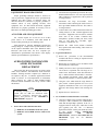
TABLES
Table 1 − Approved Personal Computers ......................................................................................
Table 2 − Audio System Board Mic Audio ALC Enable/Disable DIP Switch S1............................
Table 3 – Digital Pots ...................................................................................................................
Table 4 – Cable 19B804083P3 Color Coding ................................................................................
Table 5 − C3 Maestro-To-CEC/IMC Audio Line Requirements ....................................................
Table 6 − Boom/Gooseneck Mic Wiring*......................................................................................
Table 7 − Enhanced Audio Enclosure-To-CEC/IMC Signal Descriptions......................................
Table 8 − Enhanced Audio Enclosure-To-Call Director Signal Descriptions .................................
Table 9 – Dispatch Keyboard Cable Color Coding.........................................................................
Table 10 - C3 Maestro PC File Directories And Files ....................................................................
Table 11 – CEC/IMC Manager (MOM PC) Operations Guide Publication Numbers .....................
Table 12 – CEC/IMC Audio Lines (female DB-25 labeled "LINES 1-4") ....................................
Table 13 – Call Director (female DB-9 labeled "CALL DIR") .......................................................
Table 14 – Boom/Gooseneck Microphone (female DB-9 labeled "B/G MIC") ...............................
Table 15 – Desk Microphone (female DB-9 labeled "DESK MIC")...............................................
Copyright© February 1995, Ericsson Inc.
2
6
6
8
13
15
19
22
22
24
26
28
30
30
30
32
LBI-39101
TABLE OF CONTENTS
Page
Table 16 – Operator Headset (female DB-9 labeled "OPER H/S")................................................
Table 17 – Supervisor Headset (female DB-9 labeled "SUPER H/S")...........................................
Table 18 – Select Speaker (male DB-9 labeled "SEL SPKR").......................................................
Table 19 – Unselect Speakers –Three Total (male DB-9 labeled "UNSEL SPKRx").....................
Table 20 – Operator Footswitch (female DB-9 labeled "OPER FT. SW.") ...................................
Table 21 – Supervisor Footswitch (female DB-9 labeled "SUPER FT. SW.") ..............................
Table 22 – Optional RS-422 Input/Output (female DB-9 labeled "I/O").........................................
Table 23 – Personal Computer RS-232 Input/Output (female DB-9 labeled "PC").........................
Table 24 – Dispatch Keyboard Serial Input/Output (female DB-9 labeled "KBD").........................
Table 25 – Relay Connections (18-position terminal block labeled "RELAYS") ............................
Table 26 – Pager Input (4-position terminal block labeled "PAGING") .........................................
Table 27 – Recorder Outputs (4-position terminal block labeled "RECORDER") .........................
Table 28 – Auxiliary Audio Inputs (Not Supported).......................................................................
32
32
32
33
33
33
33
34
34
34
34
35
35
FIGURES
Figure 1 – C3 Maestro With Enhanced Audio Enclosure Equipment Interconnections...................
Figure 2 − Audio System Board DIP Switch S1 Factory Setting (ALC Enabled On All Mics)........
Figure 3 − Speaker Amp Board SW1 Factory Setting ....................................................................
Figure 4 - Plug-In RS-422 Board DB-25 Connector Pin-Out..........................................................
Figure 5 − Audio Line Input And Output Connections At Enhanced Audio Enclosure...................
Figure 6A − CEC/IMC-To-C3 Maestro Interconnections (Co-Located)..........................................
Figure 6B − CEC/IMC-To-C3 Maestro Interconnections (Remote And/Or RS-232).......................
Figure 7 – Recorder Outputs At Enhanced Audio Enclosure..........................................................
Figure 8 – Pager Inputs At Enhanced Audio Enclosure .................................................................
Figure 9 – Relay Terminal Block...................................................................................................
Figure 10 − Call Director Interface Connector At Enhanced Audio Enclosure ...............................
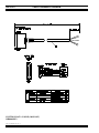
Figure 11 – Enhanced Audio Enclosure Rear Panel Connectors.....................................................
5
6
10
13
15
16
17
20
21
21
22
31
3
LBI-39101
This Page Intentionally Blank
Copyright© February 1995, Ericsson Inc.
4
LBI-39101
•
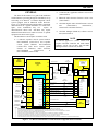
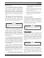
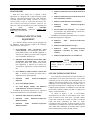
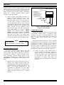
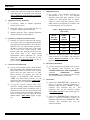
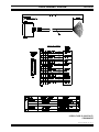
GENERAL
The intent of this manual is to guide field installation
and maintenance personnel through the installation, set-up
and testing of an EDACS® C3 Maestro dispatch console
system equipped with an Enhanced Audio Enclosure.
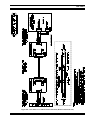
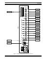
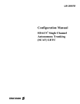
Figure 1 is a simplified diagram which indicates equipment
interconnections in a typical installation. As noted in the
figure, some installations may not
require all
interconnections shown and still others may require
additional interconnections to audio accessories or optional
equipment not shown in the figure.
•
•
•
C3 Maestro (PC) application software version 5.0x
(344A3922G12)
Enhanced Audio Enclosure firmware version 1.00
(350A1520G1)
CEC/IMC Digital Audio Switch firmware version
4.0x
(344A3564G11,
344A3565G11,
344A3567G11 and 344A3568G11)
CEC/IMC Manager (MOM PC) software version
4.0x (344A3630G11)
This document was developed in accordance with:
•
NOTE
C3 Maestro 2-speaker console system hardware
P29/7720045009 (350A1371P1) and 4-speaker
console system hardware P29/7720045010
(350A1371P2). Each above console system
includes an Enhanced Audio Enclosure
P29/7720040000
(350A1371P3)
or
P29/7720040001 (350A1371P4).
VIDEO
DISPLAY
MONITOR
PERSONAL
COMPUTER
(PC)
COM1
C3 Maestro application software version 5.0x
requires CEC/IMC Controller and Audio Board
firmware version 4.0x (or later), and CEC/IMC
Manager software version 4.0x (or later).
CABLE
19B804083P3
CON TROL DATA
CEC/IMC
DIGITAL AUDIO SWITCH
TO/FROM OTHER
CEC/IMC
INTERFACE
MODULES
RS-422 (4 W IRES)
COM2
STANDARD PC
KEYBOARD
RS-232
(3 WIRES)
(N OT USED DURING
NORMAL DISPATCH
OPERATION )
ENHANCED AUDIO ENCLOSURE
I/O BACKPLANE BOARD
DISPATCH
KEYBOARD
("CUSTOM
KBD
KEYBOARD")
AUDIO
SYSTEM
BOARD
SEE
NOTE 8.
PC
LIN ES
1-4
LINE 1 IN
SELECT
SPEAKER
SEL SPKR
4-W IRE DATA
MODEM
EQU IPMEN T
(REQU IRED FOR
A REMOTE
CON SOLE)
GSC CONTROL
DA TA
RS-232
(3 WIRES)
CABLE
P29/5010150000
(350A1371P29)
DATA
CON .
CARD
UNSELECT
SPEAKER 1
LOCAL CN TRL
RS-232
CON TROL
DATA
CABLE
19B804083P2
SELECT AU DIO
(2 W IRES)
MIC AU DIO
(2 WIRES)
UNSELECT AUDIO 1
(2 WIRES)
UNSELECT AUDIO 2
(2 WIRES)
UNSELECT AUDIO 3 OR
CD PATCHED RADIO AUDIO
(2 W IRES)
CD PATCHED MIC AUDIO OR
CONSOLE MIC AUDIO
(2 WIRES)
AUDIO
CON .
CARD
LIN E 1 OUT
LIN E 4 OUT
OPER H/S
CALL
DIR
LINE 4 OUT
LIN E 4 IN
CD RECEIVER AU DIO
(2 WIRES)
CD MIC AUDIO
(2 WIRES)
CD OUT
DESK MIC
CD IN
OPER
FT.SW .
LINE 3 OUT
SEE NOTES
6, 7 & 9.
SEE NOTES 4 & 5.
OPERATOR
FOOTSWITCH
(SEE NOTE 2)
LINE 1 OUT
LINE 2 OUT
LINE 3 IN
LINE 4 IN
DESK MIC
CIM
AUDIO
BOARD
LIN E 1 IN
SEE NOTE 3.
OPERATOR
HEADSET
CIM
CONTROLLER
BOARD
(SEE NOTE 2)
SEE
NOTES 2 & 9.
LINE 2 IN
UNSEL
SPKR1
TDM A UDIO
CD HOOK/
SENSE
CD CON TROL
(5 W IRES MAX.)
CALL
DIRECTOR
PHONE
LINES
SEE NOTE 7.
NOTES:
1. AC POWER CON NECTION S NOT SH OW N.
2. PUNCH BLOCKS, TELCO CABLES, CEC/IMC BACKPLAN E AND CON CENTRATOR CARD CABLES N OT IN DICATED.
3.
ON LY ON E U NSELECT SPEAKER SH OWN. SPEAKERS INTERCON NECTED USING CABLE P29/5010150000 (350A1371P29)
4.
SUPERVISOR HEADSET AND FOOTSWITCH, BOOM/GOOSENECK MIC, AN D CERTAIN AUDIO INPUTS SUCH AS PAGER ARE N OT SHOWN.
5. RELAY OUTPUT AN D DIGITAL IN PU T CON NECTION S ARE NOT SHOWN.
6. UNSELECT AUDIO LIN E(S) NOT REQU IRED IF CON SOLE IS NOT EQU IPPED W ITH RESPECTIVE UNSELECT SPEAKER(S).
7. IF CONSOLE SYSTEM DOES N OT SUPPORT CALL DIRECTOR TELEPHON E PATCH, ALL CD IN TERCON NECTION S ARE N OT REQU IRED.
8.
ENHANCED AUDIO ENCLOSURE LABELING MATCHES OR APPROXIMATELY MATCHES REAR PAN EL LABELING.
9. CABLE 19B804083P2 (LINE AU DIO) AND CABLE 19B804083P3 (RS-422 CON TROL DATA) PROVIDE ALL N ECESSARY C3 MAESTRO-TO-CEC/IMC IN TERCON NECTION S.
Figure 1 – C3 Maestro With Enhanced Audio Enclosure Equipment Interconnections
5
LBI-39101
PERSONAL COMPUTERS
IMPORTANT NOTE
In most cases, the Personal Computer (PC) used with
the C3 Maestro console is delivered with its hard disk drive
formatted and MS-DOS® operating system software
installed on the hard disk drive. In addition, all C3 Maestro
application software is also installed on the drive.
Hardware
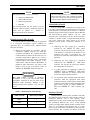
Table 1 lists the PCs approved for use with a C3
Maestro console system equipped with an Enhanced Audio
Enclosure. Use of an unapproved computer will void the
console system's warranty and support services. Subsequent
to the printing of this manual, additional PCs not listed in
the table may be approved.
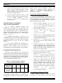
Table 1 − Approved Personal Computers
MANUFACTURER
MODEL NO. OR TYPE
Hewlett-Packard
Vectra /VL2 (486/66)
Hewlett-Packard
Vectra 25N
Hewlett-Packard
486SX/25
Operating System Software
The PC will have MS-DOS version 6.x installed on its
hard drive. Earlier versions of MS-DOS are not approved
for use with the C3 Maestro console system equipped with
an Enhanced Audio Enclosure.
NOTE
Unless otherwise noted, all procedures in this
manual should be performed in the order
presented.
BOARD SET-UP
ENHANCED AUDIO ENCLOSURE
Normally, the Enhanced Audio Enclosure is configured
at the factory for a standard C3 Maestro dispatch console
system installation. This configuration includes setting a
single 4-position DIP switch and programming all digital
pots for nominal audio input and output levels. The DIP
switch and digital pots within the Enhanced Audio
Enclosure are located on the Audio System Board.
6
In most cases, changes to the factory DIP switch
and digital pot settings ARE NOT REQUIRED.
The following information lists the normal
factory settings and the optional settings which
are available. Digital pot setting changes must
be accomplished after most of the installation
procedures presented later in this manual are
complete and the console has been powered-up.
However, for completeness of this section, a
setting procedure is included on page 7.
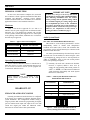
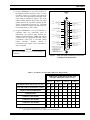
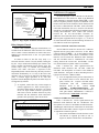
Audio System Board
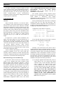
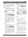
Mic Audio ALC Enable/Disable DIP Switch (S1)
DIP switch S1 on the Audio System Board is used to
independently enable or disable each microphone's
automatic level control (ALC) circuit. The switch has four
(4) positions, one for each mic that may be connected to the
Enhanced Audio Enclosure.
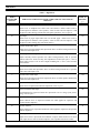
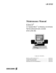
An Audio System Board ships from the factory with all
mic audio ALC circuits enabled. As shown in Figure 2, this
is accomplished by setting all four S1 switch positions to
"ON" or "CLOSED". Table 2 lists each switch position
and its corresponding microphone.
❏
Normally, mic audio ALC should not be disabled.
However, if required, disable a mic's ALC by
setting the corresponding DIP switch position to
"OFF" or "OPEN". See LBI-39100 for Enhanced
Audio Enclosure disassembly and Audio System
Board access instructions.
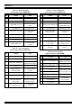
Table 2 − Audio System Board Mic Audio ALC
Enable/Disable DIP Switch S1
S1 POSITION
MICROPHONE
1
Operator Headset
2
Desk
3
Boom/Gooseneck
4
Supervisor Headset
ON
1
2
3
4
Figure 2 − Audio System Board DIP Switch S1
Factory Setting (ALC Enabled On All Mics)
LBI-39101
(on numeric keypad) keys. "Digital Pot Number:
?" is displayed in the lower left-hand side of the
C3 Maestro's display.
Digital Pots Settings
To provide computer-controlled level settings, the
Enhanced Audio Enclosure's audio input and audio output
circuits incorporate 256-position digitally-controlled
potentiometers. These digital pots, located on the Audio
System Board, allow adjustment of the Enhanced Audio
Enclosure's audio levels via the PC. Adjustments include
dispatcher-adjustable audio levels such as headset sidetone
volumes and system-level adjustments such as line input
and output levels to and from the CEC/IMC Digital Audio
Switch.
With the exception of the dispatcher's headset sidetone
volume adjustments, none of the digital pots provide
volume adjustments for the speaker or headset earphone
audio levels during normal dispatch operations. Speaker
and headset volume adjustments are accomplished at the
respective speaker or headset via mechanical pots.
NOTE
Communication module volume changes at the C3
Maestro effect CEC/IMC CIM line output levels,
not the digital pots within the Enhanced Audio
Enclosure.
Fifteen (15) dual digital potentiometer chips
(integrated circuits) are located on the Audio System Board
for a total of thirty (30) individual pots; there are no
mechanical potentiometers. All audio level adjustments are
accomplished via software. See Table 3. A dispatcher may
adjust the operator's sidetone digital pot using dedicated
keyboard keystrokes <Alt> <Vol ↑ > and <Alt> Vol ↓ > at
the Dispatch Keyboard.
All of the digital pots initially power-up with the wiper
in a 50% or centered position. The microcontroller on the
Audio System Board then immediately loads each pot in
accordance with its respective setting stored in a "working"
area of a serial EEPROM chip on the board. The EEPROM
also contains an unchangeable "default" digital pot storage
area. When shipped from the factory, the working area
matches the default area.
Digital pots may be adjusted using the C3 Maestro
application program via one of its note cards. This function
changes the settings stored in the EEPROM's working area.
Normally, this note card function should only be accessed
by the installation and/or service personnel. To change a
digital pot's setting, the following procedure may be
performed after the console's installation in complete and
it has been powered-up:
1.
From the Dispatch Keyboard, simultaneously press
the <Alt> (common control function) and the #
2.
From the numeric keypad, enter the number of the
digital pot to be changed. See Table 3. The digital
pot's existing setting is displayed.
3.
Press the ↑ (increase) or ↓ (decrease) key to
change the current setting. Changes are saved in
the EEPROM's working area as they are made.
4.
Press <Esc> to exit.
SPEAKER ASSEMBLY
Normally, a Speaker Assembly used with the Enhanced
Audio Enclosure is configured at the factory with its
minimum volume feature enabled and its maximum volume
output power set to 2 watts. This configuration is
accomplished by setting two positions on a 4-position DIP
switch located on the Speaker Amp Board.
NOTE
The following information lists the normal factory
settings and the optional settings which are
available.
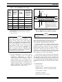
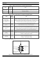
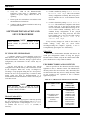
Speaker Amp Board
At each Speaker Assembly, a 4-position DIP switch
identified as SW1 is located on the Speaker Amp Board.
One position is used to enable or disable the minimum
volume level feature. A second position allows setting of
the maximum volume level to either 2 or 5 watts of output
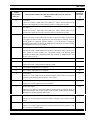
power. Factory settings are shown in Figure 3. These
switches have no effect on headset earphone output levels.
Currently, the other two DIP switch positions on SW1 are
not used.
NOTE
NOTE
SW1 may have a tape seal placed over the switches
to prevent changes.
Minimum Volume Level DIP Switch (SW1 Position 1)
When SW1 position 1 is "OFF" or "OPEN", the
minimum volume level feature is enabled. This is the
factory setting. With this setting, audio from the speaker
cannot be completely turned off by rotating the volume
control on the Speaker Assembly's front panel fully
counterclockwise.
7
LBI-39101
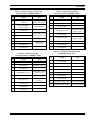
Table 3 – Digital Pots
AUDIO
SYSTEM BD.
POT NO.
1
ENHANCED AUDIO ENCLOSURE AUDIO CIRCUIT LOCATED IN /
ADJUSTS *
Call Director Input
TYPICAL
SETTING
**
120
Adjusts level of telephone line audio from Call Director. Affects audio levels to
operator/supervisor headsets, select speaker, select recorder and line output to CIM
line input (to radio) during Call Director radio patch operations. Also see pot 14.
28
Pager Input
130
Adjusts level of pager input audio from an external pager. Affects tone levels to
operator/supervisor headsets, select speaker, select recorder and line output to CIM
line input (to radio) during pager activations (PTTs).
3
Operator Headset Mic Input
75
Adjusts level of operator headset mic input audio. Does not affect boom/gooseneck mic
or desk mic audio input levels.
8
Selected Operator Mic Input
140
Adjusts currently selected operator mic (either boom/gooseneck, desk or operator
headset) audio level. In the circuitry, this adjustment is located after pots 3, 5 and 6.
Affects audio level(s) at one or more outputs including line 1, line 4, select recorder
and/or sidetone.
6
Desk Mic Input
85
Adjusts level of desk mic input audio. Does not affect boom/gooseneck mic or operator
headset mic audio input levels.
5
Boom/Gooseneck Mic Input
124
Adjusts level of boom/gooseneck mic input audio. Does not affect operator headset mic
or desk mic audio input levels.
4
Supervisor Headset Mic Input
75
Adjusts level of supervisor headset mic input audio. Also see pot 7.
7
Supervisor Headset Mic Input
140
Post adjustment for supervisor heaset mic input audio. Do not change from factory
setting. Also see pot 4.
9
Supervisor Sidetone
31
Adjusts sidetone level of supervisor headset mic audio applied to supervisor and
operator headset earphones.
10
Operator Sidetone
31
Adjusts sidetone level of operator headset mic audio applied to supervisor and operator
headsets earphones.
11
Line 1 Input
Adjusts level of line 1 input audio from CIM line 1 output. Affects audio level to select
audio output devices such as headset earphones, select speaker and select recorder.
8
125
LBI-39101
AUDIO
SYSTEM BD.
POT NO.
12
ENHANCED AUDIO ENCLOSURE AUDIO CIRCUIT LOCATED IN /
ADJUSTS *
Line 2 Input
TYPICAL
SETTING
**
125
Adjusts level of line 2 input audio from CIM line 2 output. Affects audio level to
unselect audio output devices such as unselect speaker 1 and unselect recorder.
17
Line 3 Input
125
Adjusts level of line 3 input audio from CIM line 3 output. Affects audio level to
unselect audio output devices such as unselect speaker 2 and unselect recorder.
18
Line 4 Input
125
Adjusts level of line 4 input audio from CIM line 4 output (from radio). Affects audio
levels applied to unselect audio output devices such as unselect recorder and, if a third
unselect speaker is employed, unselect speaker 3. If a Call Director is employed,
adjustment affects audio to Call Director telephone line and unselect recorder. Primary
line 4 adjustment. Also see pots 2 and 20.
20
Auxiliary Input
114
Adjusts level of line 4 input audio from CIM line 4 output (from radio). Affects audio
levels applied to select recorder, and all speakers during Call Director patch
operations. Secondary line 4 adjustment used only if console is equipped with a Call
Director. Also see pot 18.
27
N/A (pot not used)
127
15
Line 1 Output
40
Adjusts level of line 1 output audio to CIM line 1 input.
16
Line 2 Output (adjustments never required)
40
13
Line 3 Output (adjustment never required)
40
14
Line 4 Output
40
Adjusts level of line 4 output audio to CIM line 4 input. Affects audio level to patched
radio during Call Director patch operations. Also see pot 1.
21
Select Recorder Output
175
Adjusts level of audio applied to the select recorder.
19
Select Audio Output
190
Adjusts level of audio at an internal Enhanced Audio Enclosure reference point on
Audio System Board. Affects select speaker, select recorder, operator headset earphone
and supervisors headset earphone audio levels.
29
Select Speaker Output
128
Adjusts level of audio applied to the select speaker. This pot is not used as a volume
control.
30
Unselect Speaker 1 Output
128
Adjusts level of audio applied to the first unselect speaker (unselect speaker 1). This
pot is not used as a volume control.
9
LBI-39101
AUDIO
SYSTEM BD.
POT NO.
23
ENHANCED AUDIO ENCLOSURE AUDIO CIRCUIT LOCATED IN /
ADJUSTS *
Unselect Speaker 2 Output
TYPICAL
SETTING
**
128
Adjusts level of audio applied to the second unselect speaker (unselect speaker 2). This
pot is not used as a volume control.
24
Unselect Speaker 3 Output
130
Adjusts level of audio applied to the third unselect speaker (unselect speaker 3). This
pot is not used as a volume control.
22
Unselect/Telephone Recorder Output
175
Adjusts level of audio applied to the unselect recorder. This audio may be from an
unselect source or from the Call Director's telephone line.
2
Call Director Output
130
Adjusts level of audio to Call Director's telephone line (from radio). Also see pot 18.
25
Supervisor Headset Earphone Output
20
Adjusts level of audio applied to the supervisor headset earphones. This pot is not used
as a volume control.
26
Operator Headset Earphone Output
20
Adjusts level of audio applied to the operator headset earphones. This pot is not used
as a volume control.
* See Audio System Board maintenance manual for specific test points and additional alignment information.
** Numbers represent typical digital pot settings only. Factory settings are subject to change without notice as circuit improvements
occur. DO NOT ADJUST any digital pot from factory setting unless a full understanding of the consequences is known.
Specifically, with the volume control fully
counterclockwise and a nomimal audio level of 436
millivolts rms at a frequency of 1kHz from the Enhanced
Audio Enclosure, the audio output level from the speaker
will not drop below approximately 0.38 milliwatts or 55
millivolts rms across the 8-ohm speaker. This wattage
figure assumes SW1 position 2 is also "OFF" or "OPEN",
selecting the 2-watt maximum volume level. With SW1
position 2 selecting 5-watts, the minimum volume level is
approximately 1.25 milliwatts or 100 millivolts across the
8-ohm speaker.
When SW1 position 1 is "ON" or "CLOSED", the
minimum volume level feature is disabled and audio from
the speaker may be completely turned off by rotating the
volume control fully counterclockwise. This setting should
be used with caution since calls, especially calls on
unselect audio channels, are more likely to be missed.
Maximum Volume Level DIP Switch (SW1 Position 2)
SW1 position 2 allows setting of the speaker's
maximum volume level to either 2 or 5 watts of output
power. Normally, the factory setting is 2 watts. This level is
10
recommended, as it should be adequate in nearly all
dispatch environments. The 2-watt setting is selected by
setting the switch "OPEN" or "OFF". When the switch is
"CLOSED" or "ON", the maximum output power is
increased to approximately 5 watts.
Both wattage figures assume the volume control on the
Speaker Assembly's front panel is set at maximum (fully
clockwise) and a nominal audio signal input level of 436
millivolts rms at a frequency of 1 kHz is applied to the
Speaker Assembly.
ON
1
2
3
4
Figure 3 − Speaker Amp Board SW1 Factory Setting
❏
At this time, configure SW1 as required. If the
Speaker Assembly is a desktop (with case) style,
disassemble it by removing the four (4) screws
from the back of the case and then separate the
case's front and rear sections.
LBI-39101
•
RS-422 BOARD
Most PCs used within the C3 Maestro console
application are equipped with a plug-in RS-422 capable
board for serial data interfacing to the CIM within the
CEC/IMC Digital Audio Switch. Normally, no changes
from the factory set-ups are required on this board or any
other related serial COM port hardware within the PC.
However, it may be beneficial to review the information in
the
section
entitled
"CEC/IMC
INTERCONNECTIONS", subsection "Control Data
Link" (page 12) at this time.
INTERCONNECTING THE
EQUIPMENT
A C3 Maestro dispatch console system equipped with
an Enhanced Audio Enclosure requires the following
interconnections. See Figure 1:
•
•
•
•
•
•
PC-to-CEC/IMC Data Concentrator Card
control data link – Via twisted pairs, phone lines,
punch blocks and/or 4-wire modem equipment. A
100-foot (30.5 meters) pre-wired cable is supplied
for co-located RS-422 hook-ups.
Enhanced Audio Enclosure-to-CEC/IMC Audio
Concentrator Card audio link – Via 600-ohm
twisted pairs, phone lines, punch blocks and/or
mux equipment. A 100-foot (30.5 meters) prewired cable is supplied for co-located audio hookups.
PC-to-Enhanced Audio Enclosure control data
link – A 10-foot (3.05 meters) pre-wired cable is
supplied for this control data link.
Enhanced
Keyboard
Audio
Enclosure-to-Dispatch
PC-to-Video Display Monitor
PC, Video Display Monitor and Enhanced
Audio Enclosure AC Power Connections
In addition, the following connections are required if
the related external devices are used with the console:
•
•
•
Enhanced Audio Enclosure-to-Desk Mic
Enhanced
Audio
Headset Jack Box
Enclosure-to-Supervisor
Enhanced
Audio
Headset Jack Box
Enclosure-to-Operator
•
•
•
•
Enhanced Audio Enclosure-to-Boom/Gooseneck
Mic
Enhanced Audio Enclosure-to-Boom/Gooseneck
PTT and Monitor Switches
Enhanced Audio Enclosure-to-Footswitches
Enhanced
Assemblies
Audio
Enclosure-to-Speaker
PC-to-Standard PC Keyboard – The standard
PC keyboard is only utilized during console startup and maintenance operations.
In addition, the following interconnections are required
for optional equipment, if employed:
•
•
•
•
Enhanced
Equipment
Audio
Enclosure-to-Recorder
Enhanced Audio Enclosure-to-Pager
Enhanced
Equipment
Contacts
Audio
Enclosure-to-External
Controlled by Relay Form-C
Enhanced Audio Enclosure-to-Call Director
NOTE
Unless otherwise noted, all procedures in this
manual should be performed in the order
presented.
CEC/IMC INTERCONNECTIONS
The C3 Maestro console interfaces to the CEC/IMC via
a full-duplex serial control data link and a 4-wire audio
connection for the select audio and microphone link. In
addition, each unselect speaker at the console requires an
additional 2-wire connection from the CEC/IMC. Also, if
the console is interfaced to a Call Director for Call Director
telephone patch operations, an additional 4-wire audio link
between the C3 Maestro and the CEC/IMC is required. See
Figures 1 and 6 and Table 5.
As shown in Figures 1 and 6, all CEC/IMC
interconnections are made via Concentrator Cards. These
cards are located at the back of the CEC/IMC cabinet.
Control data connections are made via Data Concentrator
Cards and audio connections are made via Audio
Concentrator Cards. Typically, as shown in Figure 6, these
connections are extended out of the CEC/IMC cabinet via
Telco cables and terminations are actually made at punch
blocks located external of the CEC/IMC cabinet.
11
LBI-39101
CEC/IMC Concentrator Card pin-out details are listed
on the customer-specific system documentation print-outs.
These print-outs are included with the CEC/IMC when it
ships from the factory. See the CEC/IMC Digital Audio
Switch
Customer-Specific
System
Documentation
maintenance manual, LBI-38939 for sample print-outs and
complete print-out explanations.
Control Data Link
Overview
Either an RS-422 (four-wire) or an RS-232 (threewire) full-duplex serial control data link may be employed
between the console and the CIM within the CEC/IMC.
Since RS-422 interfacing is superior to RS-232, PCs used
within the C3 Maestro console application normally ship
from the factory with an RS-422 serial port provided for
this purpose. RS-232 has poorer noise performance than
RS-422 and therefore, it should never be used for cable runs
more than 50 feet (15.2 meters) in length. RS-422
connections may be up to 4000 feet (1219 meters) in
length.
If required for a remote console installation, fullduplex 4-wire data modems can be used between the C3
Maestro and the CEC/IMC. Typically, the PC-to-modem
and modem-to-CEC/IMC interconnections must be made
via RS-232 interconnections since many data modems do
not provide RS-422 hook-ups. These RS-232
interconnections should also not exceed 50 feet. See the
following subsections for additional remote console wiring
and modem configuration details.
At the C3 Maestro, RS-422/RS-232 serial control data
connections terminate at the PC's serial COM port.
Normally, COM1 is utilized for CEC/IMC interfacing. This
serial port is normally provided by a plug-in RS-422 board
inside the PC as described in the following section.
RS-422 Interfacing (Co-Located Hook-Ups)
In most cases, the PC used in the C3 Maestro console
system is not equipped with a main ("mother") board
RS-422 capable serial COM port. Therefore, a plug-in
RS-422 capable interface board is installed in one of the
PC's internal expansion slots and utilized for CEC/IMC
interfacing. If the plug-in RS-422 board's serial port is
configured as COM1 (normal factory configuration), the
PC's main board COM1 port is disabled to prevent
conflicts. Likewise, if the plug-in RS-422 board's serial port
is configured as COM2, the PC's main board COM2 port is
disabled. Depending upon the type of PC used, disabling of
the main board's COM port is done via either a DIP switch,
jumper, or a BIOS set-up program. For COM port
enable/disable configuration details, refer to the section
12
entitled "SOFTWARE INSTALLATION AND SET-UP
PROCEDURE", subsection "PC CMOS SET-UP
PROGRAM" later in this manual, and the PC
manufacturer's documentation.
The currently approved (factory installed) plug-in
RS-422 board is manufactured by B&B Electronics. Its
model
number
is
3PXOCC1A
(part
number
344A3927P38). Subsequent to the writing of this manual,
additional boards may be approved.
Factory-installed plug-in RS-422 boards are configured
correctly before the PC ships from the factory. This
configuration includes setting DIP switches and jumpers on
the plug-in board and disabling the PC's main board serial
COM port per manufacturer's instructions.
Configuration for the 3PXOCC1A board is:
Address Switches (S1)
(MSB)11111111(LSB)
= 3F8 Base Hex Address
Interrupt Jumper
IRQ4
Jumpers JP12 − JP15
Upper Position
Jumpers JP16 − JP17
Lower Position
If any other RS-422 plug-in serial board is used the
following board configuration is recommended:
COM Port
Port Address
Interrupt
COM1
3F8
IRQ4
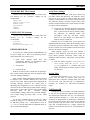
Normally, a pre-wired 100-foot (30.5 meters) cable is
supplied with the console equipment package for RS-422
control data interconnections between the CEC/IMC and a
co-located C3 Maestro console. The cable's part number is
19B804083P3. It has a female DB-25 connector on one end
for mating to the RS-422 male DB-25 connector at the PC.
The other end is "pig-tailed" (not terminated) so the cable's
24-gauge solid wires can be punched down to the correct
terminals at the required CEC/IMC punch block.
❏
If using the supplied control data cable, mate its
female DB-25 to the PC's RS-422 male DB-25
connector, route it to the CEC/IMC, shorten the
cable as required, and punch the wires to the
correct terminals. See Table 4 or the cable's
assembly diagram near the end of this manual for
wire color coding. Note the cable's "TX" wires
must connect to the "RX" pins/terminals at
CEC/IMC Data Concentrator Card or punch
block and likewise, the cable's "RX" wires must
connect to the "TX" pins/terminals at
CEC/IMC Data Concentrator Card or punch
block. Also see Figure 6A.
LBI-39101
Table 4 – Cable 19B804083P3 Color Coding
RS-422 TX(W HITE/BLUE)
PC
RS-422 CONSOLE
RS-422
PORT
SIGNAL
DB-25
PIN NO.
1
cable shield
WIRE
COLOR
n/a
TYPICAL
CEC/IMC
CONNECTION
IDENTIFICATION *
RS-422 RX(W HITE/ORANGE)
SHIELD
(W HITE/GREEN)
none **
2
TX-
white/blue
CRT 01 RX- DATA
14
TX+
blue
CRT 01 RX+ DATA
3
RX-
white/orange
CRT 01 TX+ DATA
16
RX+
orange
CRT 01 TX- DATA
7
ground
white/green
none **
1
If cable 19B802083P3 is not used for RS-422
hook-ups, see Figures 4 and 6A and/or the
manufacturer's documentation for COM port
connector pin-out details. Fabricate a cable as
required and then use it to interconnect the C3
Maesto's RS-422 control data COM port to the
appropriate CEC/IMC Data Concentrator Card as
required. Shielded cabling is recommended. Per
RS-422 specifications, cable length should be
limited to 4000 feet (1219 meters) or less.
3
15
4
16
5
17
RS-422 RX+
(ORANGE)
RS-422 TX+
(BLUE)
6
18
7
19
8
20
9
21
10
22
11
23
12
24
13
25
NOTES:
1. VIEWED FROM BA CK OF COMPUTER (MA LE DB-25) OR
WIRING SIDE OF MA TING CONNECTOR (FEMALE
DB-25).
2. TX LINES MUST CONNECT TO "CRT" RX LINES A T
CEC/IMC CONCENTRATOR CARD OR PUNCH BLOCK, +
TO + AND - TO -.
RX LI NES MUST CONNECT TO "CRT" TX LI NES AT
CEC/IMC CONCENTRATOR CARD OR PUNCH BLOCK, +
TO + AND - TO -.
3. COLOR CODING INDICA TES CA BLE 19B804083P3 WIRE
COLORS.
Figure 4 - Plug-In RS-422 Board DB-25 Connector
Pin-Out (B&B Electronics 3PXOCC1A Board)
NOTE
Do not over-tighten the screws on the DB-style
connectors.
NOTE
❏
2
14
* CEC/IMC Data Concentrator Card identification. See
customer-specific system documentation print-outs for specific
pin/terminal numbers.
** Wire not terminated at CEC/IMC punch block. Insulate and
tie back at punch block.
Cable 19B804083P3 is not compatible with
earlier plug-in RS-422 boards used with the C3
Maestro console system. These earlier plug-in
boards are manufactured by ICS and included
model numbers RS422AT-P and RS422I-P. They
can be easily identified by the presence of two
LED indicators visible on the rear plate. In
addition, the cable is also not compatible with
earlier C3 Maestro console PCs equipped with
main board RS-422 COM ports such as the Dasher
PCs manufactured by Data General.
SIGNAL GROUND
RS-232 Interfacing (Remote Console Hook-Ups Via
4-Wire Modems And RS-232 Interconnections)
When the C3 Maestro is installed at a remote location
from the CEC/IMC, a serial control data link must be
established via RS-232 connections and 4-wire full-duplex
9600 baud data modems. Since the C3 Maestro requires a
dedicated or continuous serial link (non-dial-up), a 4-wire
leased line (or equivalent) meeting 3002 data grade
specifications must be employed between the CEC/IMC and
the C3 Maestro in a remote console installation.
Figure 6B shows typical control data interconnections
for a remote console installation using RS-232 connections
and full-duplex 4-wire modems. At the CEC/IMC Data
Concentrator Card, RS-232 connections are made at J13,
not J12. Observe all notes listed in the figure if wiring an
installation of this type. Recommended modem settings
are:
•
Modem Options
DCE Rate = 9600
Originate/Answer = Originate (CEC/IMC modem)
Originate/Answer = Answer (C3 Maestro modem)
V.32 Fast Train = Enabled
Auto Retrain = Enabled
Internal/External Clock = Internal
13
LBI-39101
Dial-Up/Leased Line = Leased
Options = Retained At Disconnect
2-Wire/4-Wire = 4 Wire
•
TX Level = (as required; use -15 dBm if line loss is 0 dB)
•
Dial Backup = Manual
Loop Back Time = 15 minutes
Line Current Disconnect = Long
Control = On Until Carrier Detect
MNP Options
MNP Protocol = Enabled
Auto Fallback = Enabled (or Normal)
Flow Control = CTS Only
XON/XOFF Pass Through = Enabled
Data Compression = Disabled
Inactivity Timer = Off
Break Control = 5
DTE Options
Synchronous/Asynchronous Data = Asynchronous
DTE Rate = 9600
Character Length = 8 Bits
Parity = None
Commanded Dialer = Asynchronous
AT Command Set = Disabled
DTR Control = Disabled
DSR = Forced High
DCD = Normal
CTS = Forced High
DTE Fallback = Disabled
14
Speaker Options
Volume Control = Low
V.22 Guard Tone = Disabled
•
Dial Line Options - (not applicable; leave at factory
defaults)
Dial Line = RJ11
Long Space Disconnect = Enabled
•
•
Test Options - All Disabled (or factory defaults)
Audio Links
Audio Concentrator Cards at the back of the CEC/IMC
cabinet provide audio connections at the CEC/IMC. Like
the control data connections, audio connections are
normally extended out of the CEC/IMC cabinet via Telco
cable(s) and line terminations are actually made at punch
blocks. See Figure 6A. See the customer-specific system
documentation print-outs for Concentrator Card connector
pin-out details.
Table 5 shows line requirements between the C3
Maestro and theCEC/IMC for each audio input or output
2-wire 600-ohm twisted pair. Note that two (2) Enhanced
Audio Enclosure output pairs, Line 2 out and Line 3 out are
never used. These audio output lines are provided for future
expansion use.
At the C3 Maestro, audio connections terminate at the
DB-25 connector on the Enhanced Audio Enclosure's rear
panel. This connector is labeled "LINES 1-4". Its pin-out is
shown in Figures 5 and 6A and Table 12. It has female
contacts; therefore, the required mating connector is a male
DB-25.
Normally, a pre-wired 100-foot (30.5 meters) cable is
supplied with the console equipment package for audio
interconnections between the Enhanced Audio Enclosure
and the CEC/IMC. This 8-pair shielded cable's part number
is 19B804083P2. It has a male DB-25 connector on one end
for mating to the Enhanced Audio Enclosure's "LINES
1-4" female DB-25 connector. The other end is "pig-tailed"
(not terminated) so the cable's 24-guage solid wires can be
punched down to the correct terminals at the required
CEC/IMC's punch block.
LBI-39101
❏
If cable 19B804083P2 is used, mate its DB-25 to
the Enhanced Audio Enclosure, route it to the
CEC/IMC, shorten it as required, and punch the
wires to the correct punch block's terminals. Wire
color coding is indicated in Figure 5 and in the
cable's assembly diagram shown at the end of this
manual. Refer to the CEC/IMC customer-specific
system documentation print-outs for CEC/IMC
Audio Concentrator Card pin-outs which map over
to the punch blocks via Telco cables.
LINES
1-4
LINE 1 IN HI/+
1
(WHITE/BLUE)
LINE 1 IN LO/-
14
(BLUE)
15
LINE 1 OUT LO/(GRAY)
3
16
LINE 2 IN HI/+
4
(WHITE/ORANGE)
❏
LINE 1 OUT HI/+
(WHITE/GRAY)
2
LINE 2 IN LO/-
If cable 19B804083P2 is not used, fabricate an
equivalent cable, less unnecessary pairs, to
interconnect the required pairs between the
Enhanced Audio Enclosure's "LINES 1-4" DB-25
connector and the appropriate CEC/IMC Audio
Concentrator Card's pins or CEC/IMC punch
block's
terminals.
Shielded
cabling
is
recommended. See Figures 5 and 6 and Tables 5
and 12 for details.
17
(ORANGE)
LINE 2 OUT HI/+
(RED/BLUE)
5
18
LINE 2 OUT LO/(BLUE/RED)
6
19
LINE 3 IN HI/+
7
(WHITE/GREEN)
LINE 3 IN LO/-
20
LINE 3 OUT HI/+
(RED/ORANGE)
8
(GREEN)
21
LINE 3 OUT LO/(ORANGE/RED)
9
22
LINE 4 IN HI/+
10
(WHITE/BROWN)
LINE 4 IN LO/-
23
24
NOTE
Do not over-tighten the screws on the DB-style
connectors.
LINE 4 OUT LO/(GREEN/RED)
12
NOTES:
1. VIEWED FROM BACK OF ENHANCED
AUDIO ENCLOSURE (FEMALE DB-25)
OR WIRING SIDE OF MAT ING
CONNECT OR (MALE DB-25).
2. UNLABELED PINS ARE NO
CONNECT IONS (N.C.)
3. COLOR CODING INDICATES CABLE
19B804083P2 WIRE COLORS
LINE 4 OUT HI/+
(RED/GREEN)
11
(BROWN)
25
13
Figure 5 − Audio Line Input And Output Connections
At Enhanced Audio Enclosure
Table 5 − C3 Maestro-To-CEC/IMC Audio Line Requirements
ENHANCED AUDIO ENCLOSURE AND
CEC/IMC IDENTIFICATION (4-Wire)
LINE 1
LINE 2
LINE 3
LINE 4
CONSOLE INPUT OR OUTPUT (2-Wire)
IN
OUT
IN
OUT
IN
OUT
IN
OUT
CEC/IMC INPUT OR OUTPUT (2-Wire)
OUT
IN
OUT
IN
OUT
IN
OUT
IN
SELECT SPEAKER/HEADSET
X
MICROPHONE
UNSELECT SPEAKER 1
X
XX
UNSELECT SPEAKER 2
XX
UNSELECT SPEAKER 3 *
XX
CALL DIRECTOR PATCH *
XX
XX
"X" = 2-wire connection always required
"XX"= 2-wire connection required if console is so equipped
*
= Unselect speaker 3 not available if console is equipped with Call Director patch
15
LBI-39101
Figure 6A − CEC/IMC-To-C3 Maestro Interconnections (Co-Located)
16
LBI-39101
Figure 6B − CEC/IMC-To-C3 Maestro Interconnections (Remote And/Or RS-232)
17
LBI-39101
PERSONAL COMPUTER
Dispatch Keyboard
PC-To-Enhanced Audio Enclosure Serial Data
Interconnect Cable
The Dispatch Keyboard interfaces to the console
system via the Enhanced Audio Enclosure. This keyboard's
part number is P29/7590182003 (350A1371P17). It is
sometimes referred to as the "custom keyboard".
The PC-to-Enhanced Audio Enclosure RS-232 serial
data link uses cable P29/5010150000 (350A1371P29). This
cable has a female DB-9 connector on one end for mating
to the PC's male DB-9 serial COM port connector. The
cable's other end has a male DB-9 connector for mating to
the female DB-9 connector labeled "PC" at the Enhanced
Audio Enclosure. The cable is ten (10) feet long. It should
not be modified in any way and "extension" cables are not
recommended for this 19.2k baud serial link. Identical
cables are also used between the Enhanced Audio
Enclosure and the Speaker Assemblies.
❏
During dispatch operations, the standard PC keyboard
is not used. However, during the console set-up process,
access to this keyboard will be required:
•
for
file
management
(for
example
AUTOEXEC.BAT and CONFIG.SYS file changes
may be necessary)
•
to configure certain items via the Editor program
(see LBI-39056 for details)
•
to start the console's application program
❏
Connect the standard PC keyboard to the PC in
accordance with the manufacturer's instructions.
Typically, the plug on the keyboard's cable mates
with a connector on the back of the PC.
Video Display Monitor
Interconnect the video display monitor's video
cable to the Personal Computer in accordance with
the manufacturer's instructions.
ENHANCED AUDIO ENCLOSURE
All Enhanced Audio Enclosure interconnections are
made at the rear panel of the enclosure. Secure the cables
with cable ties as necessary.
18
Connect the Dispatch Keyboard to the Enhanced
Audio Enclosure by plugging its male DB-9
connector to the female DB-9 connector on
Enhanced Audio Enclosure's rear panel. On the
rear panel, this connector is labeled "KBD". Its
pin-out is indicated in Table 24.
Desk Mic (if used)
❏
Mate the cable's female DB-9 connector to the
PC's male DB-9 serial COM port connector used
for Enhanced Audio Enclosure interfacing.
Normally, the COM2 port is used. Mate the other
end of the cable to the
Enhanced Audio
Enclosure's DB-9 connector labeled "PC". This
interconnection is shown in Figure 1 but not in
Figure 6.
Standard PC Keyboard
❏
❏
Connect the desk microphone (option CRMC3D or
equivalent) to the Enhanced Audio Enclosure by
mating its male DB-9 connector to the female
DB-9 connector labeled "DESK MIC" on the
Enhanced Audio Enclosure's rear panel. The desk
mic's cable is five (5) feet (1.52 meters) long. The
DB-9's pin-out is shown in Table 15.
NOTE
Do not over-tighten the screws on the DB-style
connectors.
Headset Jacks (if used)
❏
At the selected location, secure each headset jack
box (part of option CRCN1W or equivalent) to the
mounting surface using the four (4) #10 threadforming screws supplied in the installation kit.
Before mounting, verify adequate clearance is
maintained for the headset's plugs. If using both
jack boxes, label them "SUPERVISOR" and
"OPERATOR".
❏
Connect each headset jack box to the Enhanced
Audio Enclosure using the 6-foot (1.83 meters)
cable supplied. This cable (part number
19C337102P1 supplied with CRCN1W) has male
DB-9 connectors on both ends. One end mates
with the female DB-9 connector at a headset jack
box and the other end mates to the female DB-9
connector at the Enhanced Audio Enclosure's rear
panel. The connectors on the rear panel are labeled
"SUPER H/S" and "OPER H/S" for the
supervisor and operator headsets respectively.
Interconnect the cables accordingly. The DB-9
connectors' pin-outs are indicated in Tables 16 and
17.
LBI-39101
NOTE
NOTE
Microphone priority is (highest to lowest):
•
Supervisory Headset Mic
•
Operator Headset Mic
•
Boom/Gooseneck Mic
•
Desk Mic
Footswitches (if used)
The boom/gooseneck mic has priority over the
desk mic when no headset is connected. Desk mic
audio will be ignored if a headset or
boom/gooseneck mic is connected.
Boom/Gooseneck Mic (if used)
A boom microphone (option CRMC3E or equivalent)
or a gooseneck microphone (option CRMC3F or
equivalent) may be connected to the Enhanced Audio
Enclosure as follows:
❏
All boom and gooseneck mic connectors (male
DB-9) must have pins 2 and 3 jumpered together
so the sense circuit will be active when the mic is
connected to the Enhanced Audio Enclosure.
Mount the microphone in accordance with the
instructions supplied with the mic. With the
gooseneck microphone, the supplied male DB-9
connector must be soldered to the cable's wires in
accordance with Table 6 after the mic's cable is
routed through the mounting surface. Connect the
boom/gooseneck male DB-9 connector to the
female DB-9 connector labeled "B/G MIC" on
Enhanced Audio Enclosure's rear panel. Cable
length is four (4) feet (1.22 meters). Table 14
indicates the "B/G MIC" connector's pin-out.
Two (2) female DB-9 connectors are located on the
rear panel of the Enhanced Audio Enclosure for footswitch
interconnections. Footswitches used with the C3 Maestro
dispatch console include single-footswitch option CRSU3B
and dual-footswitch option CRSU3C. On the
dualfootswitch, one switch (PTT) keys the mic and the other
switch is a monitor switch. A single-footswitch provides
only a PTT function. See Tables 20 and 21 for specific
connector pin-out details. Footswitch operation is as
follows:
•
•
•
CAUTION!
DO NOT connect a boom or gooseneck
microphone to one of the other female DB-9
microphone connectors at the rear panel of the
Enhanced Audio Enclosure. Damage to the
boom/gooseneck mic's magnetic voice coil may
occur.
Table 6 − Boom/Gooseneck Mic Wiring*
WIRE COLOR
DB-9 PIN NUMBER
Black
9
White
5
Shield
1
* Also see the following NOTE.
❏
Depressing the PTT switch on a footswitch
connected to the "OPER FT. SW." DB-9
connector will activate the operator's headset mic
if the headset is connected. If the headset is not
connected, the boom or gooseneck mic will
become active when this footswitch PTT switch is
depressed.
Depressing the PTT switch on a footswitch
connected to the "SUPER FT. SW.
" DB-9
connector will activate the supervisor's headset
mic if the headset is connected.
If a dual footswitch is connected to either the
"OPER FT. SW." or "SUPER FT. SW." DB-9
connectors, depressing its monitor switch will
activate the console's monitor function.
All footswitch cables terminate with male DB-9
connectors. Mate the appropriate male DB-9
footswitch connector to the respective female DB-9
connector at the Enhanced Audio Enclosure's rear
panel. Tables 20 and 21 indicate "OPER FT.
SW." and "SUPER FT. SW." connector pinouts.
Speakers (if used)
Desktop and rack-mount Speaker Assemblies used with
the Enhanced Audio Enclosure each basically consist of
mechanical hardware, one or more speakers, audio
amplification circuitry, and a volume control potentiometer.
The mechanical hardware may be of several different
varieties providing either desktop speaker operation in the
form of a self-contained single-speaker case or a rackmount version in the form of a standard 19-inch EIA rack
mount assembly. The 2-speaker rack-mount versions are
19
LBI-39101
generally assembled with one amplified speaker in the far
left-hand position (select speaker), one amplified speaker in
the far right-hand position (unselect speaker) and blank
panels installed in the two center positions. Four-speaker
consoles are
generally equipped with two separate
2-speaker rack mount assemblies.
❏
Install or mount each Speaker Assembly in a
suitable location and then interconnect it to the
Enhanced Audio Enclosure using cable
P29/5010150000 (350A1371P29). This cable is 10
feet (3.05 meters) in length. It is identical to the
cable that interconnects the PC's serial COM port
to the Enhanced Audio Enclosure. Mate the cable's
female DB-9 connector to the appropriate male
DB-9 connector on the Enhanced Audio
Enclosure's rear panel. These male connectors are
labeled "SEL SPKR" (select speaker), "UNSEL
SPKR1" (first unselect speaker), "UNSEL
SPKR2" (second unselect speaker) and "UNSEL
SPKR3" (third unselect speaker). Connect the
other end of the cable to the female DB-9
connector at the respective Speaker Assembly. If
necessary, see Tables 18 and 19 for DB-9 pin-outs.
NOTE
Load resistors are not required for
unused
Enhanced Audio Enclosure speaker outputs.
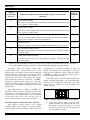
Recorder Outputs (if used)
To provide call-check recorder support, select and
unselect audio outputs are available from the Enhanced
Audio Enclosure. The unselect output may, however, be
reconfigured via software to output Call Director audio.
These unbalanced 600-ohm outputs appear at the
removable screw-terminal type terminal block labeled
"RECORDER" on the Enhanced Audio Enclosure's rear
panel.
❏
20
Interconnect the outputs to call-check recorders as
required. These outputs are not isolated from
ground through isolation transformers and the two
ground terminals are common. See Figure 7 and
Table 27 for terminal identification. See the
specifications in LBI-39100 for audio signal
output level specifications. If required, audio
output levels may be adjusted via a C3 Maestro
note card.
W IRE SECURING SCREWS
LOCATED ON TOP
W IRE ATTACHMENT:
1. UNPLUG TERMINAL BLOCK FROM
MATING CONNECTOR.
2. IF REQUIRED, COMPLETELY
LOOSEN WIRE SECURING SCREW.
3. INSERT WIRE.
4. TIGHTEN WIRE SECURING SCREW .
5. REPEAT FOR OTHER WIRES.
6. RECONNECT TERMINAL BLOCK TO
"RECORDER" MATING CONNECTOR.
RECORDER
1
4
UNSELECT/
TELEPHONE OUT
GROUND
SELECT OUT
GROUND
Figure 7 – Recorder Outputs At
Enhanced Audio Enclosure
Paging Input (if used)
Paging connections are located on a second removable
screw-terminal terminal block on Enhanced Audio
Enclosure's rear panel. A 600-ohm balanced line audio
input and a PTT (page enable) input are included. As
shown in Figure 8, this terminal block is labeled
"PAGING".
Pager balanced audio on terminals 1 and 2 is switched
in when the PTT line at terminal 3 becomes active by
grounding it to terminal 4. Typically, the PTT action is
accomplished by a relay in the pager. During a page, no
other audio signals are applied to the Line 1 output. Also,
the paging signal is sent to the headsets and speakers
approximately 16 dB lower than other audio signal levels.
❏
Connect the pager to the terminal block in
accordance with the manufacturer's instructions,
Figure 8 and Table 26. The audio terminals are
isolated from ground. See the specifications page
in LBI-39100 for audio signal input level
specifications. If required, audio input level
adjustment may be accomplished via a C3 Maestro
note card.
LBI-39101
W IRE ATTACHMENT:
1. UNPLUG TERMINAL BLOCK FROM
MATING CONNECTOR.
2. IF REQUIRED, COMPLETELY
LOOSEN WIRE SECURING SCREW.
3. INSERT WIRE.
4. TIGHTEN WIRE SECURING SCREW .
5. REPEAT FOR OTHER WIRES.
6. RECONNECT TERMINAL BLOCK TO
"PAGING" MATING CONNECTOR.
Call Director (if equipped)
PAGING
W IRE SECURING SCREWS
LOCATED ON TOP
1
4
PAGER AUDIO
INPUT +
PAGER AUDIO
INPUT PAGER PTT INPUT
GROUND
Figure 8 – Pager Inputs At Enhanced Audio Enclosure
Relay Outputs (if used)
Console-to-CEC/IMC Audio Interconnections
Form-C relay contacts (single-pole double-throw) are
available from the Enhanced Audio Enclosure for external
device control. Contact connections are made at the screwterminal type terminal block on the rear panel labeled
"RELAYS".
As shown in Table 25, the first relay (relay 1) is
activated when the console is keyed (PTTed). During the
key, the relay's common and normally-open contacts close
and its common and normally-closed contacts open. The
second relay's (relay 2) common and normally-open
contacts close while <Alt><F10> is depressed at the
Dispatch Keyboard. Like the first relay, this relay's action is
considered "momentarily" as it is only in the active state
when the <Alt><F10> keys are depressed. The third relay's
(relay 3) contacts toggle open/close at an <Alt><F9>
keystroke from the Dispatch Keyboard. The other relays are
not supported by software.
❏
As required, connect the relay contact outputs to
external equipment. See Table 25 and Figure 9.
Specified contact rating for all relays is 0.75 amps
at 26 Vdc. Open contact isolation is specified to
500 Vrms at 60 Hz. Isolation between any relay
terminal and the Enhanced Audio Enclosure's
ground is also specified to 500 Vrms at 60 Hz.
W IRE SECURING SCREWS
LOCATED ON TOP
RELAYS
1
18
RELAY OUTPUT
TERMINAL 1
As shown in Figure 1, all C3 Maestro-to-Call Director
interconnections at the console are made at the Enhanced
Audio Enclosure's connector labeled "CALL DIR". A Call
Director telephone patch also requires an additional 4-wire
balanced line between the Enhanced Audio Enclosure and
the console’s CIM within the CEC/IMC. At the CEC/IMC,
CIM audio channel/line four (4) is used for Call Director
interfacing. CD control data interfacing is handled over the
existing RS-232/RS-422 serial control data interface
between the PC and the CEC/IMC. Therefore, no
additional control data link must be added to support Call
Director patch equipment. Refer to Figures 1, 5, 6 and 10
for interconnection details and the following discussion on
CEC/IMC line audio line requirements.
RELAY OUTPUT
TERMINAL 18
W IRE ATTACHMENT:
1. UNPLUG TERMINAL BLOCK FROM MATING CONNECTOR.
2. IF REQUIRED, COMPLETELY LOOSEN WIRE SECURING SCREW.
3. INSERT W IRE.
4. TIGHTEN WIRE SECURING SCREW.
5. REPEAT FOR OTHER W IRES.
6. RECONNECT TERMINAL BLOCK TO "RELAYS" MATING CONNECTOR.
All CEC/IMC line audio in to and out of a C3 Maestro
dispatch console system enters and leaves via the DB-25
connector labeled "LINES 1 - 4" on the Enhanced Audio
Enclosure's rear panel. If the console is connected to a Call
Director, Line 4 between the Enhanced Audio Enclosure
and the CEC/IMC must be established for CD audio
routing between the console and the CEC/IMC. In this
case, the third unselect speaker audio is not available.
Table 7 describes the audio signals between the
Enhanced Audio Enclosure and the CIM within the
CEC/IMC. The descriptions are relative to the Enhanced
Audio Enclosure. All signals on these 600-ohm pairs have
typical levels between -5 dBm to 0 dBm.
❏
If not accomplished in the previous instructions in
this manual, install a 4-wire balanced line (two
pairs) between the required CEC/IMC Audio
Concentrator Card and
Enhanced Audio
Enclosure. Refer to the
section entitled
"CEC/IMC
INTERCONNECTIONS"
for
details. In most cases, the pre-wired 100-foot audio
cable (part number 19B804083P2) is utilized as
described in the "Audio Links" subsection.
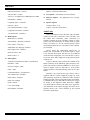
Console-to-Call Director Interconnections
Table 8 describes the various signals between the
Enhanced Audio Enclosure and the Call Director. The
descriptions are relative to the Enhanced Audio Enclosure.
All Enhanced Audio Enclosure connections are made at the
"CALL DIR" female DB-9 connector. Figure 10 and Table
13 indicate the connector's pin-out.
❏
Interconnect the Enhanced Audio Enclosure to the
Call Director as required per Tables 8 and 13,
Figure 10, and the Call Director's documentation.
Figure 9 – Relay Terminal Block
21
LBI-39101
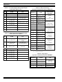
Table 7 − Enhanced Audio Enclosure-To-CEC/IMC Signal Descriptions
TYPE
INPUT /
OUTPUT
Patched Radio
Input
Radio audio from CIM TX channel/line 4. During a CD telephone patch, this audio is
heard at the telephone.
CD/Operator Mic
Output
Telephone/operator mic audio to CIM RX channel/line 4. This audio is heard at the radio.
USE
Table 8 − Enhanced Audio Enclosure-To-Call Director Signal Descriptions
INPUT /
OUTPUT
USE
ON-HOOK N.O.
(pin 1) and
ON-HOOK COMMON
(pin 6)
Output
Optional – Normally-open relay contact (Form-A). Closure generated when the
console disconnects the CD from the CEC/IMC. Used to put CD on-hook, if an
input exists. The relay remains energized for approximately 1.2 seconds. This value
is fixed in the firmware and cannot be changed. Relay contact rating:
0.75 A @ 26 Vdc, 500 Vrms isolation from ground @ 60 Hz
CD HOOK SENSE IN
(pin 2) *
Input
Active low when the CD is placed off-hook. Typically connects to a dry contact
(SPST switch, Form-A relay, etc.) from Call Director.
CD JACK SENSE IN
(pin 3) *
Input
Optional – Active low when a handset is plugged into the CD. This handset
overrides all audio connections to the Enhanced Audio Enclosure. The operator
talks directly to the phone via the handset instead of using the console’s headset or
mic/speaker. Typically connects to a dry contact from Call Director.
GROUND (pin 4) *
n/a
Signal ground for CD HOOK SENSE IN and CD JACK SENSE IN sense inputs.
CD IN
(pins 5 and 9)
Input
Audio from the CD (telephone mic). This audio is heard by a radio in patch
operation, or by operator headset in normal operation. 600-ohm balanced input:
-26 dBm to -14 dBm, typically -20 dBm.
CD OUT
( pins 7 and 8)
Output
Radio/operator mic audio to the CD (telephone receiver). This audio is heard by the
telephone. 600-ohm balanced output:
-11 dBm to +1 dBm, typically -5 dBm.
NAME
* GROUND (pin 4) is common for CD HOOK SENSE IN (pin 2) and CD JACK SENSE IN (pin 3)
This ground is not isolated from chassis ground.
CALL
DIR
1
6
CD HOOK SENSE IN
2
CD JACK SENSE IN
3
7
8
GROUND
ON-HOOK N.O.
ON-HOOK COMMON
HI/+
LO/-
CD OUT
HI/+
LO/-
CD IN
4
9
5
NOTE:
1. VIEWED FROM BACK OF ENHANCED
AUDIO ENCLOSURE OR WIRING SIDE
OF MAT ING CONNECTOR.
Figure 10 − Call Director Interface Connector At Enhanced Audio Enclosure
22
LBI-39101
EQUIPMENT ROOM GROUNDING
Proper grounding techniques should be observed in
order to protect the equipment and service personnel from
lightning and other sources of electrical surges. All
consoles should be connected to properly grounded 3terminal outlets. If used, lightning arrestors, UPS
equipment, and all other console-associated equipment
should also be properly grounded. If necessary, refer to
LBI-39067 for detailed grounding procedures.
❏
Disconnect the Dispatch Keyboard from the Logic
Board installed in the PC. If a new keyboard (with
DB-9 connector) is supplied, this old keyboard is
no longer needed.
❏
Disconnect the large PC-to-Audio Tower
interconnect cable connecting the Audio Tower to
the Logic Board installed in the PC. This cable is
no longer needed.
❏
At the Audio Tower, label and then disconnect all
cabling between it and external equipment and
accessories. Equipment and accessories includes
items such as the Volume Controller Box,
microphones, speakers, headset jack boxes, audio
lines to and from the CEC/IMC, pager,
recorder(s), Call Director, etc.
❏
Remove the Audio Tower, Volume Controller
Box, speakers and related cabling. These items are
no longer needed.
AC POWER AND UPS EQUIPMENT
All consoles require 115 or 230 Vac (47 to 63 Hz)
power sources. As a minimum, each outlet should be
circuit-breaker protected per local building codes.
UPS protection is optional. Maximum required UPS
wattage rating for a single console system should be based
on the required maximum sums of the Enhanced Audio
Enclosure (200 watts max.), the PC's computer (per
manufacturer's specifications) and the PC's video display
monitor (per manufacturer's specifications).
2.
AUDIO TOWER-TO-ENHANCED
AUDIO ENCLOSURE
REPLACEMENT
This section lists the steps necessary to replace earlier
Audio Tower hardware with Enhanced Audio Enclosure
hardware. Existing Personal Computer (PC) hardware is
not replaced, only the C3 Maestro application software
which it executes. To avoid duplication of information,
many references are made to other Enhanced Audio
Enclosure-related installation and set-up sections within
this manual.
Logic Board Removal
❏
Review the procedures in the documentation
included with the PC relating to expansion board
installation/removal.
❏
Remove the PC's outside cover in accordance with
the manufacture's instructions.
❏
Identify and remove the Logic Board installed in
one of the PC's expansion slots. The large PC-toAudio Tower interconnect cable (disconnected in
step 1) mated with this board's DB-37 connector.
The Dispatch Keyboard's small round DIN
connector also mated to a connector on this board.
❏
Using the screw which held the Logic Board in
place, install a blank expansion slot cover (not
supplied). Installation of this cover will prevent
dust and other foreign matter from entering the
PC.
❏
Replace the PC's outside cover.
NOTE
NOTE
If installing a complete new C3 Maestro console
system (new PC and new Enhanced Audio
Enclosure equipment), disregard this section
entirely and proceed to the POWER-UP
"
PROCEDURE" on page 25.
1.
Power-Down and Cable Disconnections
❏
REMOVE AC POWER from the PC system.
❏
REMOVE AC POWER from the Audio Tower
system.
3.
PC-To-Enhanced Audio Enclosure Serial Link
❏
Using PC's CMOS set-up program, enable the PC's
serial port (DB-9 connector) for COM2/address
2F8h and interrupt IRQ3 operation. If the PC is
equipped with two serial ports, enable the second
port (typically port "B"). The C3 Maestro's
application software sets the port's baud rate. Refer
to
the
section
entitled
"SOFTWARE
INSTALLATION
AND
SET-UP
PROCEDURE", subsection "PC CMOS SET-UP
PROGRAM"
(page
26)
for
additional
information.
23
LBI-39101
❏
4.
❏
If necessary, obtain C3 Maestro application
software V5.0 (or later).
❏
Install this software on PC's hard disk drive in
accordance with the supplied instructions.
❏
Normally, no console-to-CIM serial link changes
are necessary. However, if upgrading/replacing the
plug-in RS-422 board installed in one of the PC's
expansion slots (for improved static protection),
the DB-25 connector which plugs to this board
will, in most cases, require rewiring. Older
RS-422 boards have different pin-outs from the
newer boards. Refer to the plug-in boards'
documentation and/or LBI-39055 for
pin-out
information. Also see the subsection in this
manual entitled "Control Data Link" (begins on
page 12) and Figure 6 in this manual.
❏
If using existing modular cabling, cut the modular
plugs off modular cables. Maintain connections to
the CEC/IMC Audio Concentrator Card or punch
blocks. Next, wire these audio lines to a male
DB-25 connector (not supplied) and mate the
connector to the Enhanced Audio Enclosure's
"LINES 1-4" female DB-25 connector. See the
subsection in this manual entitled "Audio Links"
(begins on page 14) for additional information.
If using the pre-wired 100-foot audio cable,
remove the existing modular cabling connections
from the CEC/IMC Audio Concentrator Cards or
punch blocks. Next, wire the 100-foot audio cable
to the CEC/IMC Audio Concentrator Card/punch
block in accordance with the subsection in this
manual entitled "Audio Links" (begins on page
14).
The existing (old) Dispatch Keyboard was
disconnected in step 1. If a new Dispatch
Keyboard (with male DB-9 connector) is not
supplied and this keyboard must be utilized,
replace its small round DIN connector with a
DB-9 connector (not supplied) in accordance with
the following table. Also see Table 24:
Table 9 – Dispatch Keyboard Cable
Color Coding
Optional: Delete the old C3 Maestro application
software from the PC's hard disk drive.
Console-To-CIM Audio Link
❏
24
Dispatch Keyboard
Console-To-CIM Serial Control Data Link
❏
6.
7.
Application Software Installation
❏
5.
Connect this serial port (COM2) to the Enhanced
Audio Enclosure in accordance with subsection
"PC-To-Enhanced Audio Enclosure Serial Data
Interconnect Cable" in this manual (page 18).
❏
8.
CABLE
WIRE
COLOR
USE
1
red
dc power
2
white
keyboard data
4
green
ground
6
(bare)
shield
Connect the Dispatch Keyboard to the Enhanced
Audio Enclosure in accordance with subsection
entitled "Dispatch Keyboard" in this manual
(page 18).
Microphones & Headsets
❏
9.
MALE
DB-9 PIN
NUMBER
Connect existing mics and headset jack boxes to
the Enhanced Audio Enclosure per section
"INTERCONNECTING THE EQUIPMENT",
subsection
"ENHANCED
AUDIO
ENCLOSURE" in this manual (begins on page
18). No wiring changes are necessary.
Footswitches
❏
Audio Tower "FOOTSWITCH 1" should now be
used as an operator footswitch. Connect it to
Enhanced Audio Enclosure's "OPER FT. SW."
connector. This footswitch keys all
nonsupervisory mics. See the subsection entitled
"Footswitches (if used)" in this manual (page 19)
for additional details.
❏
Audio Tower "FOOTSWITCH 2" should now be
used as a supervisor footswitch. Connect it to
Enhanced Audio Enclosure's "SUPER FT. SW."
connector. This footswitch keys only the
supervisor's headset.
LBI-39101
10. Speakers
Speakers used with the Audio Tower are un-amplified
units; therefore, they cannot be used with the Enhanced
Audio Enclosure. Speakers used with the Enhanced Audio
Enclosure are amplified units and each includes a volume
control. The Volume Controller Box is not employed in
Enhanced Audio Enclosure applications.
❏
Existing (old) speakers and the Volume Controller
Box were disconnected in step 1. Install and cable
the new Speakers Assemblies (desktop or rackmount) to the Enhanced Audio Enclosure in
accordance with the subsection entitled "Speakers
(if used)" in this manual (page 19).
13. Relay Outputs
❏
14. Call Director
❏
11. Recorder Outputs
❏
If recorder outputs were utilized in the Audio
Tower installation, rewire these connections to the
Enhanced Audio Enclosure in accordance with the
subsection entitled "Recorder Outputs (if used)"
in this manual (page 20). Audio Tower recorder
connections utilized a large removable terminal
block; Enhanced Audio Enclosure recorder
connections utilize a smaller removable terminal
block - the terminal block must be changed.
However, note the pin-out sequence is identical.
Audio Tower I/O Board J1 terminal 1 (top
terminal of "UNSELECT RECORDER" and
"SELECT RECORDER" terminal block)
corresponds to Enhanced Audio Enclosure
"RECORDER" terminal 1. Likewise, Audio
Tower I/O Board J1 terminal 4 (bottom terminal)
corresponds to Enhanced Audio Enclosure
"RECORDER" terminal 4.
If a pager was utilized with the Audio Tower
installation, rewire these connections to the
Enhanced Audio Enclosure in accordance with the
subsection entitled "Paging Input (if used)" in
this manual (page 20). Audio Tower pager
connections utilized a large removable terminal
block; Enhanced Audio Enclosure pager
connections utilize a smaller removable terminal
block - the terminal block must be changed.
However, note the pin-out sequence is identical.
Audio Tower I/O Board J2 terminal 1 (top
terminal of "PAGE INPUT" and "PAGE PTT"
terminal block) corresponds to Enhanced Audio
Enclosure "PAGER" terminal 1. Likewise, Audio
Tower I/O Board J2 terminal 4 (bottom terminal)
corresponds to Enhanced Audio Enclosure
"PAGER" terminal 4.
If the Audio Tower was connected to a Call
Director, connect the male DB-9 connector on the
cable from the Call Director (disconnected in step
1 from Audio Tower's I/O Board "CALL
DIRECTOR" DB-9) to the Enhanced Audio
Enclosure's female DB-9 "CALL DIR" connector.
See the subsection entitled "Call Director (if
equipped)" in this manual (page 21) for additional
details. Line coupling transformers utilized
between an earlier ("Phase 1") Audio Tower and
the Call Director are not required and they should
be removed in Enhanced Audio Enclosure
applications.
15. Completion
❏
Continue with the following power-up procedure.
POWER-UP PROCEDURE
❏
The following C3 Maestro power-up procedure is
recommended:
1.
If the Personal Computer and/or monitor are
equipped with a voltage selector switch, verify the
switches are positioned correctly. The power
supply within the Enhanced Audio Enclosure will
operate from any ac voltage from approximately
100 Vac to 240 Vac; no voltage selection switch
exits on it.
2.
On the three (3) units, verify each power switch is
in the off position.
3.
Connect the PC, video display monitor and the
Enhanced Audio Enclosure to a 115 or 230 Vac
source. Normally, 1½ duplex ac receptacles are
required for the three (3) power cords. Refer to the
PC and monitor documentation as necessary.
Extension cords should not be used with the C3
Maestro console system.
4.
Verify all equipment is properly grounded.
5.
Power-up the Enhanced Audio Enclosure. The
on/off power switch lights when ac power is
applied and the switch is in the on position.
12. Paging Inputs
❏
If any relay outputs were utilized in the Audio
Tower installation, rewire these connections to the
Enhanced Audio Enclosure in accordance with the
subsection entitled "Relay Outputs (if used)" in
this manual (page 21).
25
LBI-39101
6.
Verify the
LED on the Enhanced Audio
Enclosure's front panel is illuminated. This
signifies the power supply within the unit is
operating.
7.
Power-up the PC and monitor in accordance with
the manufacture's instructions.
8.
Continue with the software installation and set-up
procedures that follow.
SOFTWARE INSTALLATION AND
SET-UP PROCEDURE
NOTE
Unless otherwise noted, all procedures in this
manual should be performed in the order
presented.
•
•
COM2 is enabled by setting "Serial Port B"
to "Serial 2F8h IRQ3". This is the standard
factory configuration. Normally, this serial port is
used to interface the PC to the Enhanced Audio
Enclosure.
COM1 is disabled by setting "Serial Port A"
to "Off". This disables the computer's main board
COM1 serial port so the plug-in RS-422 board
used for CEC/IMC control data interfacing can be
set to COM1 without conflicting. This is the
standard factory configuration. If the plug-in
RS-422 board is not being used and the main
board COM1 port is used for CEC/IMC control
data interfacing, set "Serial Port A" to
"Serial 3F8h IRQ4".
If any necessary changes are made to the COM1 or
COM2 settings, verify they are saved before
rebooting/resetting the computer. Typically, a save is
accomplished by pressing the <F3> function key.
Other PCs
PC CMOS SET-UP PROGRAM
C3 Maestro software is factory-installed on the PC's
hard disk drive and the software is configured properly for
standard installations. Therefore, during a typical console
configuration, the information in this section may be
bypassed.
All PCs used with the C3 Maestro store start-up
configurations in CMOS memory. This information is read
by the computer's BIOS and it may be changed by
executing a set-up program during the PC's boot process.
Execute the PC's set-up program only if a built-in (main
board) COM port must be disabled/enabled or if
documentation included with the PC deems it necessary for
some other reason.
NOTE
Time and date will be correctly set by the
CEC/IMC Manager (MOM PC) when the console
is on-line with the CEC/IMC.
Hewlett-Packard PCs
Typically, the HP set-up program is started by pressing
the <F2> function key when prompted with "Setup=F2"
during the boot process. Verify/configure "Serial Port
A" (COM1) and Serial
"
Port B" (COM2) as
necessary:
26
Refer to the documentation included with the PC for
COM port configuration details. If using the plug-in
RS-422 board as COM1, verify the PC's main board COM1
port is disabled. Also verify COM2 is enabled.
FILE DIRECTORIES AND CONTENTS
Table 10 specifies PC file directories and files directly
applicable to the C3 Maestro console. The MS-DOS file
directory and its files are not shown. Also, other utility files
not listed in the table may exist in a utility directory which
are not essential to the operation of the C3 Maestro
application program.
Table 10 - C3 Maestro PC File Directories And Files
ROOT DIRECTORY
(C:\)
AUTOEXEC.BAT
CONFIG.SYS
COMMAND.COM*
IO.SYS*
MSDOS.SYS*
CONSOLE
DIRECTORY
(C:\CONSOLE)
AUXIO.DAT
CONFIG.DAT
CONKEY.COM
CONSOLE.EXE
EDITOR.EXE
ENGLISH.DAT
ENTITY.DAT
FONT33.DAT
SETUPS.DAT
* MS-DOS 6.0 or later. IO.SYS and MSDOS.SYS are hidden
files.
LBI-39101
AUTOEXEC.BAT File Contents
Serial Ports' Settings
Contents of the AUTOEXEC.BAT file located in the
root directory (C:\) are as follows. Changes are not
recommended:
Normally, the PC's COM1 serial port is utilized for
CEC/IMC control data interfacing. The baud rate of this
port may be set to operate at 19,200 or 9600. The 19,200
setting is recommended for all co-located console hook-ups.
The 9600 baud setting is normally required when a data
modem is employed between the console and the CEC/IMC
in a remote console installation.
@ECHO OFF
PATH=C:\DOS;C:\UTIL
PROMPT $P$G
CD\CONSOLE
CONKEY
CONSOLE
❏
CONFIG.SYS File Contents
Contents of the CONFIG.SYS file located in the root
directory (C:\) are
as follows. Changes are not
recommended:
FILES=20
BUFFERS=40
DEVICE=C:\DOS\ANSI.SYS
EDITOR PROGRAM
If necessary, the Editor program (EDITOR.EXE) can
be used to change one or more or the following consolerelated parameters (non-inclusive list):
•
Serial Ports' Settings (baud rates and
serial/parallel interface; PC-to-Enhanced Audio
Enclosure interface is always serial)
•
Set-Up Titles
•
Call Director ID
With the exception of the Call Director ID parameter,
these console-related parameters cannot be changed via the
CEC/IMC Manager (MOM PC).
Most console-related configuration parameters should
be changed at the CEC/IMC Manager and sent to the
console. Users of the Editor program must understand the
CEC/IMC Manager should be the central point of
databasing and configuration for all C3 Maestro consoles
connected to the CEC/IMC Digital Audio Switch. Changes
made locally via the Editor program will override settings
previously made via the
CEC/IMC Manager.
Correspondingly, changes made via the CEC/IMC Manager
will override settings previously made via the Editor
program.
At the PC's standard keyboard, execute the Editor
program by typing EDITOR followed by an <Enter> from
an MS-DOS prompt. The current directory must be
C:\CONSOLE. See the LBI-39056 for additional details on
the use of the Editor program.
If necessary, use the Editor program to change the
COM1 baud rate. Save the change to the hard disk
drive. 19,200 baud is the factory (default) setting.
See LBI-39056 for additional details. The
CEC's/IMC's CIM has auto-baud sensing;
therefore, no CIM changes are required when a
baud rate change is made here.
Normally, the PC's COM2 serial port is utilized for
Enhanced Audio Enclosure control data interfacing. In this
case the port operates at 9600 baud. This setting is fixed in
the PC's software and in the Enhanced Audio Enclosure's
firmware. It cannot be changed.
Editor program version 5.0 (and later) includes a
setting to select Enhanced Audio Enclosure (serial) or
Logic Board (parallel) interfacing. When using an
Enhanced Audio Enclosure, enable/verify serial operation
as follows:
❏
From the Editor program's "CONFIGURATION
DATA" screen, verify the Serial
"
Audio
System" parameter is "Y" (enabled). This is the
factory default setting for Editor program version
5.0 (and later).
Set-Up Titles
From the Editor program's "USER PROFILE DATA"
screen, enter the titles as required. These titles are
displayed on the C3 Maestro's "Change Setup" note cards.
Ten (10) titles, each with thirty-one (31) alphanumeric
characters, are available. See LBI-39056 for additional
details.
Call Director ID
Call Director ID is a secondary console ID number that
is only used for Call Director telephone patch operations.
The default value for this ID is zero (0) − no Call Director.
Valid Call Director ID range is 1 - 16382. The zero setting
should not be changed unless a Call Director is attached to
the console and the console will be used for Call Director
patch operations. The ID resides in the unit/console ID
space and it should therefore be a unique (unused) ID
number. Console ID and Call Director ID should never be
identical.
27
LBI-39101
❏
If using CEC/IMC firmware version 2.x (and
earlier), set the Call Director ID number from the
Editor program's "CONFIGURATION DATA"
form. Save changes to the hard disk drive. See
LBI-39056 for complete details.
❏
If using CEC/IMC firmware version 3.x (and
later) the Call Director ID setting should be made
via the CEC/IMC Manager's "Console
Hardware Configuration" option and then
sent to the console.
Digital Audio Switch Installation, Set-Up And
Troubleshooting maintenance manual, LBI-38938. See
"STEP 6 - CONSOLE CONFIGURATION" in
LBI-38938 for details.
Console User Profile Configuration
From the CEC/IMC Manager, user profile data is sent
only to the targeted console. When a target console receives
user profile data from the CEC/IMC Manager it will send
an acknowledgment to the CEC/IMC Manager. Send user
profile data to the console as follows:
1.
From the CEC/IMC Manager's "CEC/IMC MOM
Options" main menu, select the "Console
Configuration" option. This will display the
console configuration menu.
2.
From this menu, select the "Console User
Profile" option. This will display the
"CONSOLE
USER
PROFILE
CONFIGURATION" screen.
3.
Verify the Console"
"
number matches the CIM's
console assignment number defined by the CIM's
Controller Board DIP switches.
4.
Verify the Unit
"
ID" number does not conflict
with any other console or radio ID number (LID)
in the system.
In a new console installation, after starting the C3
application program, databases must be initialized as
described in the following section. This must be
accomplished before dispatch operations can be performed.
5.
Select the correct "Setup" and then make any
required modification(s) to the configuration. Save
the new configuration. Refer to LBI-38938 and the
applicable CEC/IMC Manager publication listed
in Table 11 for complete details.
DATABASE INITIALIZATION
6.
Press the <F7> function key to send the Console
User Profile configuration to the console.
7.
When the "User Profile Successfully
Written..." message is displayed, return to the
CEC/IMC Manager's main menu. If an "Unable
to Write User Profile..." message
appears or no message appears after ten (10)
seconds, the CIM may not be properly installed
and/or configured. Check Controller Board
installation and DIP switch settings. Refer to the
CEC/IMC Digital Audio Switch Installation,
Set-Up And Troubleshooting maintenance manual,
LBI-38938.
A
"User
Profile
Successfully Written..." message must
be received before continuing.
RUNNING THE C3 MAESTRO
APPLICATION PROGRAM
The C3 Maestro application program will
automatically start when the PC is powered up via the
CONSOLE(.EXE) statement in the AUTOEXEC.BAT file.
After exiting the program, restart it again from the PC's
standard keyboard by typing CONSOLE followed by an
<Enter> at the MS-DOS prompt. The current directory
must be C:\CONSOLE.
The CONKEY.COM program is also run via the
AUTOEXEC.BAT file at boot-up. This program allows the
C3 application program to be quickly restarted by simply
pressing function key <F10> on the PC's standard
keyboard.
When the console initializes from a cold start, the
procedures presented in the following subsections should be
performed to insure proper operation. All console databases
are initialized via commands from the CEC/IMC Manager
(MOM PC). See the appropriate manual listed in Table 11
for CEC/IMC Manager operating details.
Table 11 – CEC/IMC Manager (MOM PC)
Operations Guide Publication Numbers
SOFTWARE
VERSION
PUBLICATION
NUMBER
V2.1x
V3.0x
V4.0x
LBI-38911 LBI-39024 LBI-39124
V5.x
(to be
determined)
Basically, except for sending console configurations,
all procedures presented assume all CEC/IMC console
configurations are complete as described in the CEC/IMC
28
System Manager Database Uploads
System Manager databases contain all system
information for all defined entities (units, groups, sites).
LBI-39101
These databases can be downloaded by the console by
requesting database uploads from the CEC/IMC Manager.
Since this data is broadcast to all consoles in the CEC/IMC
system, if possible, all consoles should be on-line when this
upload occurs. This avoids having to repeat the process for
other consoles at a later time.
1.
From the CEC/IMC Manager's "CEC/IMC MOM
Options" main menu, select the "System
Manager Data" option. This will display the
System Manager data menu.
2.
Select "Upload From System Manager".
3.
From the "SYSTEM
MANAGER
UPLOAD
STATUS" screen, select <F1> then <F8> for a full
unit upload. After the upload is complete, exit the
unit upload screen by pressing <Esc>.
4.
From the "SYSTEM
MANAGER
UPLOAD
STATUS" screen, select <F2> then <F8> for a full
group upload. After the upload is complete, exit
the group upload screen by pressing <Esc>.
5.
6.
From the "SYSTEM
MANAGER
UPLOAD
STATUS" screen, select <F6> then <F8> for a full
site upload. After the upload is complete, exit the
site upload screen by pressing <Esc>.
From the "System Manager Data" menu,
select the "Upload From MOM PC" option.
7.
From the "MOM PC BASED SYSTEM MANAGER
UPLOAD STATUS" screen, select <F3> then
<F8> for a full conventional channel upload. After
the upload is complete, exit the conventional
upload screen by pressing <Esc>.
8.
From the "MOM PC BASED SYSTEM MANAGER
UPLOAD STATUS" screen, select <F5> then
<F8> for a full console upload. After the upload is
complete, exit the console upload screen by
pressing <Esc>.
NOTE
System Manager database uploads must be
accomplished before sending console privilege
lists.
Console Privilege Lists
Each console must be sent its privilege list from the
CEC/IMC Manager as follows:
1.
From the CEC/IMC Manager's "CEC/IMC MOM
Options" main menu, select the "Console
Configuration" option. This will display the
console configuration menu.
2.
From this menu, select
Privilege List" option.
the
Console
"
3.
From the "CONSOLE PRIVILEGE LIST
UPLOAD" screen, enter the number of the console
(1 - 32).
4.
Select <F7> to send the privilege list data to the
console.
Saving Database Information
At the C3 Maestro console, the following database
information is saved automatically to the PC's hard disk
drive after the last record is received. No user action is
required:
•
User Profiles
•
Hardware Configurations
The following data is not saved automatically, but on
demand or by prompt:
•
System Manager Upload Data
•
CEC/IMC Manager Upload Data
•
Module Set-Ups
Upload data should be saved after it is transferred to
the console's PC. Modules set-ups should also be saved
after changes are made to the modules. Saving prevents
configuration problems if the PC's power is cycled or if it is
rebooted. To save upload data and module set-ups, press
<F10> on either keyboard. This will save the data to the
PC's hard disk.
SOFTWARE INSTALLATION AND
UPGRADES
As previously stated, all C3 Maestro application
software is installed on the PC's hard disk drive at the
factory. Refer to publication SRN-1000-xx which is
included with a software upgrade package if a reinstallation or an upgrade is necessary.
ENHANCED AUDIO ENCLOSURE
CONNECTOR PIN-OUTS
Tables 12 thru 28 that follow list the pin-outs of the
connectors on the Enhanced Audio Enclosure's rear panel.
"NAME" designations in the tables correspond to the
labeling used on the I/O Backplane Board schematic
29
LBI-39101
diagram. Figure 11 shows the rear panel and serves as a
guide to the desired table(s).
Table 12 – CEC/IMC Audio Lines
(female DB-25 labeled "LINES 1-4")
PIN
NAME
USE *
1
LINE_1_IN+
2
LINE_1_IN-
Line 1
balanced input
3
no connection
4
LINE_2_IN+
5
LINE_2_IN-
6
no connection
7
LINE_3_IN+
8
LINE_3_IN-
9
no connection
10
LINE_4_IN+
11
LINE_4_IN-
12
no connection
13
no connection
14
LINE_1_OUT+
15
LINE_1_OUT-
16
no connection
17
LINE_2_OUT+
18
LINE_2_OUT-
19
no connection
20
LINE_3_OUT+
21
LINE_3_OUT-
22
no connection
23
LINE_4_OUT+
24
LINE_4_OUT-
25
no connection
Line 2
balanced input
Line 3
balanced input
PIN
NAME
USE
1
ON_HOOK_NO
output;
see pin 6 and Table 8
2
CD_HOOK_SENSE_IN
3
CD_JACK_SENSE_IN
4
PS_GND_IN
5
CALL_DIRECTOR_IN-
½ CD bal. line input
6
ON_HOOK_COMMON
common for pin 1
7
CALL_DIRECTOR_OUT+
8
CALL_DIRECTOR_OUT-
CD balanced
line ouput
9
CALL_DIRECTOR_IN+
½ CD bal. line input
Line 1
balanced output
Line 2
balanced output
Line 3
balanced output
Line 4
balanced output
inputs; see Table 8
Table 14 – Boom/Gooseneck Microphone
(female DB-9 labeled "B/G MIC")
Line 4
balanced input
* With respect to the Enhanced Audio Enclosure. For example,
pins 1 and 2 are Enhanced Audio Enclosure line inputs; audio
signals on these inputs originate from the CEC's/IMC's CIM
line outputs. Also see Figure 5.
30
Table 13 – Call Director
(female DB-9 labeled "CALL DIR")
PIN
NAME
USE
1
AGND
mic audio shield
2*
PS_GND_IN
ground for pin 3
3*
B/G_MIC_SENSE_IN
mic connected/not
connected sense input
4
PS_GND_IN
ground for pin 6
5
B/G_MIC_IN_GND
mic audio ground
for pin 9
6
B/G_PTT_IN
PTT input; see pin 4
7
no connection
8
no connection
9
B/G_MIC_IN
mic audio input;
see pin 5 and Table 6
* Jumper pins 2 and 3 on mating connector.
J18
F
KBD
J17
F
PC
J16
F
I/O
J15
F
SUPER
OPER
See Table 14
F
See Table 13
F
M
J11
M
J10
J7
F
J6
F
See Table 15
See Table 12
AUX. IN
4
J2
1
4
J13
PAGING
ON
POWER
OFF
1
RECORDER
J1
See Table 16
J5
F
OPER
H/S
DESK
MIC
See Table 17
J4
F
See Table 18
J3
M
J9
See Table 20
M
J8
FT. SW.
See Table 21
J14
F
18
J20
See Table 22
See Table 19
B/G
MIC
See Table 27
See Table 23
See Table 19
CALL
DIR
LINES
1-4
See Table 26
See Table 24
See Table 19
SUPER
H/S
(TOP)
SEL
SPKR
CD/
UNSEL UNSEL UNSEL
SPKR1 SPKR2 SPKR3
RELAYS
1
See Table 25
DIG IN
1
J19
18
LBI-39101
Figure 11 – Enhanced Audio Enclosure Rear Panel Connectors
31
LBI-39101
Table 17 – Supervisor Headset
(female DB-9 labeled "SUPER H/S")
Table 15 – Desk Microphone
(female DB-9 labeled "DESK MIC")
PIN
NAME
1
no connection
2
PS_GND_IN
3
USE
PIN
NAME
1
no connection
ground for pin 3
2
no connection
MONITOR_PTT_IN
monitor PTT (enable)
input
3
SUPR_JACK_SENSE_IN
headset connected/not
connected sense input
4
PS_GND_IN
ground for pin 6
4
PS_GND_IN
ground for pins 3 & 6
5
DESK_MIC_IN_GND
mic audio ground
for pin 9
5
SUPR_HEADSET_
MIC_IN_GND
mic audio ground
for pin 9
6
DESK_MIC_PTT_IN
PTT input; see pin 4
6
SUPR_PTT_IN
PTT input; see pin 4
7
no connection
7
8
no connection
SUPR_HEADPHONE_
OUT
headphone/earphone
output; see pin 8
8
9
DESK_MIC_IN
SUPR_HEADPHONE_
OUT_GND
headphone/earphone
ground for pin 7
SUPR_HEADSET_
MIC_IN
mic audio input;
see pin 5
mic audio input;
see pin 5
9
Table 16 – Operator Headset
(female DB-9 labeled "OPER H/S")
PIN
NAME
1
no connection
2
no connection
USE
Table 18 – Select Speaker
(male DB-9 labeled "SEL SPKR")
USE
PIN
NAME
USE
1
SELECT_SPEAKER_OUT
high-impedance
speaker audio output
ground for pin 1
3
OPR_JACK_SENSE_IN
headset connected/not
connected sense input
2
SELECT_SPKR_OUT_GND
4
PS_GND_IN
ground for pins 3 & 6
3
no connection
5
OPR_HEADSET_
MIC_IN_GND
mic audio ground
for pin 9
4
+12V
6
OPR_PTT_IN
PTT input; see pin 4
5
+12V
7
OPR_HEADPHONE_OUT
headphone/earphone
output; see pin 8
6
no connection
7
PS_GND_IN
8
PS_GND_IN
9
no connection
8
9
32
OPR_HEADPHONE_
OUT_GND
headphone/earphone
ground for pin 7
OPR_HEADSET_MIC_IN
mic audio input;
see pin 5
speaker amp 12 Vdc
power; see pins 7 & 8
speaker amp
power grounds
LBI-39101
Table 21 – Supervisor Footswitch
(female DB-9 labeled "SUPER FT. SW.")
Table 19 – Unselect Speakers –Three Total
(male DB-9 labeled "UNSEL SPKRx"*)
PIN
NAME
USE
PIN
NAME
1
UNSELECT_SPEAKER_
x_OUT
high-impedance
speaker audio output
1
no connection
2
PS_GND_IN
2
USEL_SPEAKER_
x_OUT_ GND
ground for pin 1
3
no connection
3
no connection
4
MONITOR_PTT_IN
4
+12V
5
no connection
5
+12V
6
no connection
6
SUPER_PTT_IN
7
PS_GND_IN
7
no connection
8
PS_GND_IN
8
no connection
9
no connection
9
no connection
speaker amp 12 Vdc
power; see pins 7 & 8
speaker amp
power grounds
USE
ground for pins 4 & 6
monitor PTT (enable)
input; see pin 2
Supervisor PTT
input; see pin 2
* "x" = unselect speaker number (1, 2 or 3)
Table 22 – Optional RS-422 Input/Output
(female DB-9 labeled "I/O")
Table 20 – Operator Footswitch
(female DB-9 labeled "OPER FT. SW.")
PIN
NAME
1
no connection
2
PS_GND_IN
3
no connection
4
MONITOR_PTT_IN
5
no connection
6
B/G_PTT_IN
7
no connection
8
no connection
9
no connection
PIN
NAME
USE
1
no connection
2
no connection
3
no connection
4
TX_RS485_DATA_OUT+
½ serial data output
5
RX_RS485_DATA_IN+
½ serial data input
6
no connection
7
no connection
8
TX_RS485_DATA_OUT-
½ serial data output
9
RX_RS485_DATA_IN-
½ serial data input
USE
ground for pins 4 & 6
monitor PTT (enable)
input; see pin 2
B/G PTT input;
see pin 2
33
LBI-39101
Table 23 – Personal Computer RS-232 Input/Output
(female DB-9 labeled "PC")
PIN
NAME
USE
1
no connection
2
TX_PC_DATA_OUT
serial data output
3
RX_PC_DATA_IN
serial data input
4
no connection
5
PS_GND_IN
6
no connection
7
no connection
8
POWER_STATUS_OUT
9
no connection
ground for pins 2, 3 & 8
power-up status output
Table 24 – Dispatch Keyboard Serial Input/Output
(female DB-9 labeled "KBD")
Table 25 – Relay Connections
(18-position terminal block labeled "RELAYS")
TERMINAL
NAME*
ACTIVATION
METHOD
1
RELAY_1_NO
console
2
RELAY_1_C
PTT
3
RELAY_1_NC
(momentary action)
4
RELAY_2_NO
Dispatch Keyboard
5
RELAY_2_C
<Alt><F10>
6
RELAY_2_NC
(momentary action)
7
RELAY_3_NO
Dispatch Keyboard
8
RELAY_3_C
<Alt><F9>
9
RELAY_3_NC
(toggle action)
10
RELAY_4_NO
(currently not
11
RELAY_4_C
supported
PIN
NAME
USE
12
RELAY_4_NC
by software)
RELAY_5_NO
+5V_KB_OUT
keyboard dc power
output
13
1
(currently not
14
RELAY_5_C
supported
15
RELAY_5_NC
by software)
16
RELAY_6_NO
(currently not
17
RELAY_6_C
supported
18
RELAY_6_NC
by software)
2
RX_KEYBOARD_
DATA_IN
serial data input
(data from keyboard)
3
TX_KEYBOARD_
DATA_OUT
serial data output
(not used)
4
PS_GND_IN
ground for pins 1, 2 & 3
5
no connection
6
no connection
7
no connection
8
no connection
9
no connection
* See Table 9 for wire color coding.
34
* "NO" = normally-open contact; "C" = common contact;
"NC" = normally-closed contact.
Table 26 – Pager Input
(4-position terminal block labeled "PAGING")
TERMINAL
NAME
USE
1
PAGER_IN+
2
PAGER_IN-
balanced
audio input
3
PAGER_PTT_IN
PTT (enable) input
4
PS_GND_IN
ground for pin 3
LBI-39101
Table 27 – Recorder Outputs
(4-position terminal block labeled "RECORDER")
Table 28 – Auxiliary Audio Inputs (Not Supported)
(1/8-inch stereo phone jack labeled "AUX. IN")
TERMINAL
NAME
USE
TERMINAL
NAME
USE
1
USEL/TELE_
RECORDER_OUT
unselect/telephone
recorder output
tip
AUX_LEFT_IN
left chn. input (green)
ring
AUX_RIGHT_IN
right chn. input (red)
2
AGND
ground for pin 1
3
SELECT_
RECORDER_OUT
select recorder
audio output
4
AGND
ground for pin 3
sleeve
AUX_IN_GND grounds T and R (black)
35
LBI-39101
CABLE ASSEMBLY DIAGRAM
CONTROL DATA CABLE (100-FOOT)
19B804083P3
(Made from 19B804083, Sh. 4, Rev. 1)
36
CABLE ASSEMBLY DIAGRAM
LBI-39101
AUDIO CABLE (100-FOOT)
19B804083P2
(Made from 19B804083, Sh. 3, Rev. 1)
37
Ericsson Inc.
Private Radio Systems
Mountain View Road
Lynchburg, Virginia 24502
1-800-528-7711 (Outside USA, 804-528-7711)
Printed in U.S.A.