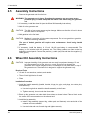
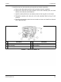
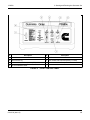
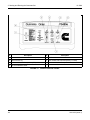
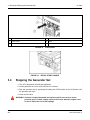
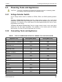
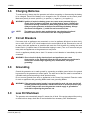
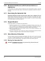
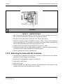
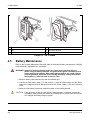
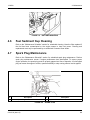
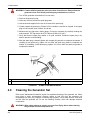
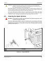
1
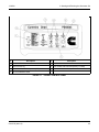
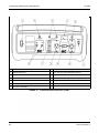
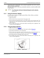
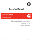
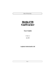
Operator Manual
Portable Generator Set
EGMBD,
EGMBD,
EGMBD,
EGMBE,
EGMBE,
EGMBE,
EGMBE,
English
12−2008
P5350ec
P5350ce
P5500ec
P5450ec
P5450ec
P5550ec
P6500ec
914−0103 (Issue 3)
Table of Contents
1. SAFETY PRECAUTIONS ...............................................................................................................
1
1.1 Exhaust Gas Is Deadly ............................................................................................................
1
1.2 Gasoline is Flammable / Explosive..........................................................................................
1
1.3 Generator Voltage is Deadly....................................................................................................
2
1.4 Moving Parts Can Cause Severe Personal Injury or Death ....................................................
2
1.5 Battery Gases Are Explosive ...................................................................................................
2
1.6 General Precautions ................................................................................................................
2
2. INTRODUCTION.............................................................................................................................
5
2.1 About This Manual ...................................................................................................................
5
2.2 Model Identification ..................................................................................................................
5
2.3 Wheel Kit..................................................................................................................................
9
2.4 Fuel Requirements...................................................................................................................
9
2.5 Assembly Instructions ............................................................................................................
10
2.6 Wheel Kit Assembly Instructions ...........................................................................................
10
2.7 Engine Oil Recommendations ...............................................................................................
12
2.8 Starting Battery ......................................................................................................................
12
3. STARTING AND RUNNING THE GENERATOR SET..................................................................
13
3.1 Control Panel .........................................................................................................................
13
3.2 Pre-Start Checks....................................................................................................................
19
3.3 Starting the Generator Set.....................................................................................................
20
3.4 Stopping the Generator Set ...................................................................................................
22
3.5 Powering Tools and Appliances ............................................................................................
23
3.6 Charging Batteries .................................................................................................................
25
3.7 Circuit Breakers .....................................................................................................................
25
3.8 Grounding ..............................................................................................................................
25
3.9 Low Oil Shutdown ..................................................................................................................
25
3.10 Electrical Interference with Communications or Appliances ................................................
26
3.11 Exercising the Generator Set...............................................................................................
26
3.12 Engine Break-In ...................................................................................................................
26
3.13 Out-of-Service Protection.....................................................................................................
26
4. MAINTENANCE ............................................................................................................................
29
4.1 Maintenance Schedule ..........................................................................................................
29
914-0103 (Issue 3)
i
Table of Contents
12-2008
4.2 General Inspections ...............................................................................................................
30
4.3 Changing Engine Oil ..............................................................................................................
30
4.4 Air Filter Maintenance ............................................................................................................
31
4.5 Battery Maintenance ..............................................................................................................
32
4.6 Fuel Sediment Cup Cleaning.................................................................................................
33
4.7 Spark Plug Maintenance........................................................................................................
33
4.8 Cleaning the Generator Set ...................................................................................................
34
4.9 Cleaning the Spark Arrester ..................................................................................................
35
5. TROUBLESHOOTING ..................................................................................................................
37
6. SPECIFICATIONS ........................................................................................................................
41
7. IMPORTANT INFORMATION FOR CALIFORNIA USERS ..........................................................
43
ii
914-0103 (Issue 3)
1
Safety Precautions
Thoroughly read the Operator Manual before operating the generator set. Safe operation
and top performance can only be obtained when equipment is operated and maintained
properly.
The following symbols, found throughout this manual, alert you to potentially dangerous
conditions to operators, service personnel, and the equipment.
DANGER: This symbol alerts you to an immediate hazard that will result in
severe personal injury or death.
WARNING: This symbol alerts you to a hazard or unsafe practice that can result in
severe personal injury or death.
CAUTION: This symbol alerts you to a hazard or unsafe practice that can result in personal
injury or damage to equipment or property.
1.1
Exhaust Gas Is Deadly
· Operate the generator set outdoors only. Stay away from the exhaust outlet.
· Make sure generator set exhaust will not enter windows, doors, vents, or air intakes of
adjacent buildings, vehicles, or boats.
· NEVER USE THE GENERATOR SET INSIDE a home, garage, crawl space, barn, shed,
cabin, boat, boat house, RV, or tent, or in a confined outdoor space such as an alley, ditch,
parking garage, or courtyard, or in any other space where exhaust can accumulate. Note
that HAZARDOUS CARBON MONOXIDE LEVELS FROM ENGINE EXHAUST CAN
ACCUMULATE INDOORS, EVEN WHEN ALL WINDOWS AND DOORS ARE OPEN AND
FANS ARE RUNNING.
· Even when you use a generator set correctly, CO may leak into the home. ALWAYS use a
battery-powered or battery-backup CO alarm in the home.
· If you feel sick, dizzy, or weak after the generator set has been running, move to fresh air
RIGHT AWAY. See a doctor. You could have carbon monoxide poisoning.
1.2
Gasoline is Flammable / Explosive
· Refuel the generator set outdoors only.
914-0103 (Issue 3)
1
1. Safety Precautions
12-2008
· Static electric sparks caused by fuel flowing through a service station pump nozzle can
ignite gasoline. Never fill the generator set with a service station pump nozzle. Instead, fill
a safety tank sitting on the ground and then slowly transfer fuel to the generator set from
the safety tank.
· DO NOT fill fuel tanks while the engine is running. A hot engine can ignite the fuel.
· To prevent fire due to fuel leakage, always close the fuel valve and let the generator set
cool before transporting it or storing it in a confined space.
· DO NOT SMOKE OR ALLOW AN OPEN FLAME near the generator set. Keep flames,
sparks, electrical switches, pilot lights, electrical arcs, arc-producing equipment, and all
other sources of ignition well away.
1.3
Generator Voltage is Deadly
· DO NOT CONNECT THE GENERATOR SET DIRECTLY TO ANY BUILDING
ELECTRICAL SYSTEM. Back-feed could cause electrocution of utility line workers and
could damage equipment. An approved switching device must be used to prevent
interconnections. A trained and experienced electrician must make electrical connections
when the generator set is used for emergency power.
· Make sure clothing, shoes, and skin are dry when handling electrical equipment.
· Never operate the generator set in rain or snow or when it is sitting on wet ground.
1.4
Moving Parts Can Cause Severe Personal Injury or
Death
· Before performing any maintenance on the generator set, disconnect the spark plug wire.
· Always keep hands away from moving parts.
· Do not wear loose clothing or jewelry while servicing the generator set. Loose clothing and
jewelry can become caught in moving parts. Jewelry can short out electrical contacts
causing sparks, flame and electrical shock.
· Make sure that fasteners and clamps on the generator set are tight. Keep guards in
position over fans, rotors, etc.
1.5
Battery Gases Are Explosive
· Wear safety glasses when servicing batteries.
· Do not smoke.
· To reduce arcing when disconnecting or reconnecting battery cables, always disconnect
the negative (–) cable of the battery first and reconnect it last.
1.6
General Precautions
· Keep children away from the generator set.
· Wear hearing protection when near an operating generator set.
2
914-0103 (Issue 3)
12-2008
1. Safety Precautions
· Keep a multi-class ABC fire extinguisher readily at hand. Class A fires involve ordinary
combustible materials, such as wood and cloth. Class B fires involve combustible and
flammable liquids and gaseous fuels. Class C fires involve live electrical equipment. (ref.
NFPA No. 10).
· Benzene and lead may be found in gasoline and have been identified by some state and
federal agencies as causing cancer or reproductive toxicity. Do not ingest, inhale, or
contact gasoline.
· Used engine oils have been identified by some state and federal agencies as causing
cancer or reproductive toxicity. Do not ingest, inhale, or contact used engine oil or its
vapors.
· Keep the generator set clean and dry at all times. Excess grease and oil can catch fire
and/or accumulate dirt, which can cause overheating.
· Do not store anything on the generator set, such as oil cans, oily rags, chains or wooden
blocks. A fire could result or operation could be adversely affected.
· Do not work on the generator set when you are mentally or physically fatigued or have
consumed alcohol or drugs.
914-0103 (Issue 3)
3
1. Safety Precautions
12-2008
This page is intentionally blank.
4
914-0103 (Issue 3)
2
Introduction
2.1
About This Manual
This manual covers the generator sets listed on the front cover. Study this manual and observe
all of its warnings and precautions. Using and maintaining the generator set properly will result
in longer generator set life, better performance, and safer operation.
2.2
Model Identification
Be ready to provide the generator set model and serial numbers on the generator set nameplate
when contacting Cummins Onan for parts, service, or product information. The nameplate and
its location on the generator set is illustrated in the Figure below.
WARNING: Many troubleshooting procedures or replacement of parts present hazards
that can result in equipment damage and severe personal injury or death.
Only trained and experienced service personnnel with knowledge of fuels,
electricity, and machinery hazards should perform service procedures.
Review the Safety Precautions section of this manual.
FIGURE 1.
914-0103 (Issue 3)
NAMEPLATE LOCATION FOR P5350, P5350C, P5450E, P5450EC, AND P5550E
GENERATOR SETS
5
2. Introduction
12-2008
FIGURE 2.
6
NAMEPLATE LOCATION FOR P5500 AND P6500
914-0103 (Issue 3)
12-2008
2. Introduction
No.
Description
No.
Description
1
Fuel Tank Cap
6
Recoil Starter Grip
2
Fuel Gauge
7
Control Panel
3
Choke Lever
8
Muffler
4
Fuel Level
9
Spark Plug Boot
5
Air Cleaner
NOTE: Carb models (P5350c and P5450ec) may include additional components not shown.
FIGURE 3.
COMPONENT LOCATIONS (P5350, P5350C, P5450E, P5450EC, P5500, AND P5550E)
914-0103 (Issue 3)
7
2. Introduction
No.
12-2008
Description
Description
1
Fuel Tank Cap
6
Recoil Starter Grip
2
Fuel Gauge
7
Battery
3
Choke Lever
8
Control Panel
4
Fuel Valve
9
Muffler
5
Air Cleaner
10 Spark Plug Boot
FIGURE 4.
8
No.
COMPONENT LOCATIONS (P6500)
914-0103 (Issue 3)
12-2008
2.3
2. Introduction
Wheel Kit
The assembled wheel kit shown below is standard equipment on P5350, P5350c, P5450e,
P5450ec, and P5550e models.
FIGURE 5. WHEEL KIT INSTALLED
2.4
Fuel Requirements
Use clean, fresh unleaded gasoline with an octane rating (anti-knock index) of 87 or higher.
During part of the year, only mandated "oxygenated" gasoline may be available. While
"oxygenated" gasoline is acceptable for use, it is not preferable. Using leaded gasoline will
result in extra maintenance to remove combustion changer and spark plug deposits. Do not use
starting fluids and do not use gasoline or gasoline additives (de-icers) containing methanol.
Methanol is corrosive to fuel system components.
WARNING: Evaporative starting fluids, such as ether, are highly explosive which can
result in severe personal injury or death. Do not use starting fluids.
CAUTION: Methanol is corrosive to fuel system components. Do not use gasoline or gasoline
additives containing methanol.
WARNING: Gasoline is highly flammable and explosive which can result in severe
personal injury or death. Do not smoke if you smell gasoline or are near fuel
tanks or gasoline-burning equipment, or are in the area sharing ventilations
with such equipment. Keep flames, sparks, electrical swithces, pilot lights,
arc-producing equipment,and all other sources of ignition well away from the
area.
914-0103 (Issue 3)
9
2. Introduction
2.5
12-2008
Assembly Instructions
1. Remove the generator set from the box.
WARNING: The generator set is heavy. Dropping the generator set can cause severe
personal injury or death. Keep feet and hands clear when lifting the generator
set.
2. If necessary, install the wheel kit (see the Wheel Kit Assembly Instructions).
3. Add oil to the generator set.
CAUTION: Too little oil can cause severe engine damage. Make sure that the oil level is above
the Add mark on the dipstick.
4. Add gasoline to the fuel tank.
CAUTION: Methanol is corrosive to fuel system components. Do not use gasoline or gasoline
additives containing methanol.
The use of leaded gasoline will require extra maintenance. Avoid using leaded
gasoline.
5. If necessary, install the battery. A 12 volt, 14L-A2 type battery is recommended. The
battery is not included with the generator set. The battery cables are often tucked up
behind the control panel. Connect the positive (+) cable (red) first and then the negative (–)
cable (green).
2.6
Wheel Kit Assembly Instructions
CAUTION: Improper handling of the generator set can result in equipment damage. Do not
turn the generator set on the side, top, or end. Doing so may damage the
generator set or cause dangerous fuel or oil leakage. Do not place items on top of
the generator set. The wheel kit is designed to support the generator only.
Required Tools
· 10 and 12 mm wrenches, sockets, and ratchet
· Three 6-inch high blocks of wood
· Pliers
Installation Procedure
1. Install the handle assembly (handle, bracket, hinge pin, grips, end plugs, two cotter pins,
and fasteners).
a. Use two long bolts to attach the handle assembly to the frame.
b. Tighten securely; do not crush the frame tube.
2. Block up the generator set under both frame tubes as shown below. Place a block under
the center of the cross-member on the exhaust end.
3. Install the leg assembly.
a. Install a leg assembly (support leg, rubber pad, and fastener) onto each side of the
exhaust end cross-member.
b. Use two bolts and nuts for each leg and tighten securely.
10
914-0103 (Issue 3)
12-2008
2. Introduction
4. Install the wheel and axle assembly (axle assembly and wheel assemblies).
a. Remove the rubber pads secured to the frame where the axle is attached.
b. Remove the cotter pins and loose washers from the axle assembly (axle, two loose
washers, two cotter pins, and fasteners).
c. Install the wheels (flat free tire and wheel); make sure the long hub is to the inside.
d. Reinstall the washers and cotter pins on the axle assembly. Bend one leg of each
cotter pin.
e. Place the axle assembly under the cross member as shown and install four bolts and
nuts. Tighten securely.
No.
Description
No.
Description
1
Frame
4
Support Leg Assembly
2
Wheel Assembly
5
Wooden Blocks
3
Axle Assembly
6
Handle Assembly
FIGURE 6. INSTALLED WHEEL KIT
914-0103 (Issue 3)
11
2. Introduction
2.7
12-2008
Engine Oil Recommendations
Use American Petroleum Institute (API) performance class SL or SJ engine oil or better. Also
look for Society of Automotive Engineers (SAE) viscosity grade oil (see the table below).
Choose the viscosity grade appropriate for the ambient temperature expected until the next
scheduled oil change. Refer to the Specifications section for engine oil capacity.
Single-grade SAE 30 oil is best when temperatures are consistently above freezing. Multi-grade
oils are better when wide temperature variations are expected.
TABLE 1. OIL VISCOSITY VS. TEMPERATURE
Expected Ambient Temperatures
30o F (0 C) and higher
SAE Viscosity Grade
30
10o F to 100o F (-12o C to 38o C)
15W-40
0o F to 80o F (-18o C to 27o C)
10W-30
10W-40
-20o F to 50o F (-28o to 10o C)
5W-30
2.8
Starting Battery
A starting battery is used in EGMBE models (P5550e, P5450e, P5450ec, and P6500).
The electric starter requires a 12 volt starting battery (12 volt, 14L-A2). The battery is not
included with the generator set.
Refer to the "Maintenance" section and any instructions available from the battery manufacturer
for battery maintenance. Note that as long as the generator set is run regularly, the automatic
battery recharging system on the engine should maintain battery charge.
12
914-0103 (Issue 3)
3
Starting and Running the Generator
Set
3.1
Control Panel
The control panels are illustrated below. The control switches, meters, output receptacles, and
circuit breaker reset buttons are grouped for convenient operation.
No.
Description
No.
Description
1
Start/On/Off Switch
6
One 120/240 VAC, 30A Receptacle (L14-30R)
2
DC Circuit Breaker Reset
7
Earth Ground Lug
3
Two 120 VAC, 20A Receptacles (GFCI)
8
120 VAC or 120/240 VAC Selector Switch
4
AC Circuit Breaker Reset
9
One 120 VAC, 30A Receptacle (L5-30R)
5
AC Voltmeter
10 12 Volt DC Terminals
FIGURE 7.
914-0103 (Issue 3)
P5550E CONTROL PANEL
13
3. Starting and Running the Generator Set
No.
Description
12-2008
No.
Description
1
On/Off Switch
5
AC Circuit Breaker Reset
2
Earth Ground Lug
6
One 120/240 VAC 30A Receptacle (L14-30R)
3
Two 120 VAC, 20A Receptacles (GFCI)
7
Two 120 VAC, 20A Receptacles
4
AC Circuit Breaker Reset
FIGURE 8.
14
P5350 CONTROL PANEL
914-0103 (Issue 3)
12-2008
No.
3. Starting and Running the Generator Set
Description
No.
Description
1
On/Off Switch
5
AC Circuit Breaker Reset
2
Earth Ground Lug
6
One 120/240 VAC 30A Receptacle (L14-30R)
3
Two 120 VAC, 20A Receptacles (GFCI)
7
Two 120 VAC, 20A Receptacles
4
AC Circuit Breaker Reset
FIGURE 9.
914-0103 (Issue 3)
P5350C CONTROL PANEL
15
3. Starting and Running the Generator Set
No.
Description
12-2008
No.
Description
1
Start/On/Off Switch
5
AC Circuit Breaker Reset
2
Earth Ground Lug
6
One 120/240 VAC 30A Receptacle (L14-30R)
3
Two 120 VAC, 20A Receptacles (GFCI)
7
Two 120 VAC, 20A Receptacles
4
AC Circuit Breaker Reset
FIGURE 10.
16
P5450E CONTROL PANEL
914-0103 (Issue 3)
12-2008
No.
3. Starting and Running the Generator Set
Description
No.
Description
1
Start/On/Off Switch
5
AC Circuit Breaker Reset
2
Earth Ground Lug
6
One 120/240 VAC 30A Receptacle (L14-30R)
3
Two 120 VAC, 20A Receptacles (GFCI)
7
Two 120 VAC, 20A Receptacles
4
AC Circuit Breaker Reset
FIGURE 11.
914-0103 (Issue 3)
P5450EC CONTROL PANEL
17
3. Starting and Running the Generator Set
No.
Description
12-2008
No.
Description
1
Start/On/Off Switch
7
Two 120 VAC, 20A Receptacles (GFCI)
2
DC Breaker Reset Switch
8
One 120 VAC, 30A Receptacle (L5-30R)
3
AC Circuit Breaker Reset
9
120 VAC or 120/240 VAC Selector Switch
4
AC Voltmeter
10 One 120/240 VAC, 30A Receptacle (L14-30R)
5
AC Circuit Breaker Reset
11 Earth Ground Lug
6
12 Volt DC Terminals
FIGURE 12.
18
P5500 AND P6500 CONTROL PANEL
914-0103 (Issue 3)
12-2008
3.2
3. Starting and Running the Generator Set
Pre-Start Checks
DANGER: EXHAUST GAS IS DEADLY! THE INDOOR USE OF A GENERATOR SET
CAN KILL QUICKLY.
Exhaust gases contain carbon monoxide, an odorless and colorless gas. Carbon
monoxide is poisonous and can cause unconsciousness, severe personal injury, and
death. Symptoms of carbon monoxide poisoning include:
· Dizziness
· Nausea
· Headache
· Weakness and sleepiness
· Throbbing in temples
· Muscular twitching
· Vomiting
· Inability to think coherently
IF YOU OR ANYONE ELSE EXPERIENCE ANY OF THESE SYMPTOMS, GET INTO FRESH
AIR IMMEDIATELY. Then:
· Seek immediate advice from poison control, medical center, or 911. Be aware that:
· CO symptoms can be mistaken for flu, dehydration, food poisoning, or other illness.
· Injury or death can occur later when in fresh air and apparently recovering.
· Call the fire department to determine when it is safe to re-enter the area.
Operate the generator set OUTDOORS only. Stay away from and upwind of the exhaust
outlet.
Make sure the exhaust will not enter windows, doors, vents, or air intakes of adjacent
buildings, vehicles, or boats.
Never use the generator set inside a home, garage, crawl space, barn, shed, cabin, boat,
boat house, RV, or tent; or in a confined outdoor space such as an alley, ditch, parking
garage, or courtyard, or in any other space where exhaust can accumulate. Hazardous
carbon monoxide levels from generator set exhaust can accumulate indoors even when
windows and doors are open and fans are running.
Even when you use a generator set correctly, CO may leak into the home. ALWAYS use a
battery-powered or battery-backup CO alarm in the home.
If you feel sick, dizzy, or weak after the generator set has been running, move to fresh air
RIGHT AWAY. See a doctor. You could have carbon monoxide poisoning.
914-0103 (Issue 3)
19
3. Starting and Running the Generator Set
12-2008
Before the first start of the day and after every eight hours of operation, perform GENERAL
INSPECTIONS and any scheduled maintenance due, as indicated in the Periodic Maintenance
Schedule. If the generator set has been in storage, return it to service as instructed in the
"Out-of-Service Protection" section.
WARNING: Moving parts can cause severe personal injury or death. Hot exhaust parts
can cause severe burns. Make sure all protective guards are properly in
place before starting the generator set.
A non-functioning GFCI, or a damaged or overloaded extension cord, can cause
electrocution or fire. Test the GFCI for proper operation. Make sure all extension cords
are in good condition, are rated for outdoor use, have the proper plugs, and have the
proper amp and voltage ratings.
WARNING: Gasoline is highly flammable and expolsive and can be ignited by static
electric sparks caused by fuel flowing through a service station pump nozzle
which can result in severe personal injury or death. Never fill the generator
set with a service station pump nozzle. Instead, fill a safety tank sitting on
the ground and then slowly transfer fuel to the generator set from the safety
tank.
1. Locate the generator set outdoors in a dry, level place and chock the wheels, if so
equipped.
2. Check fuel and oil levels, and fill as necessary.
WARNING: If the generator neutral supply is not grounded to earth, the user may be left
without ground fault protection, which could result is serious personal injury
or death. Always make sure the generator neutral supply is grounded to
earth before operating the generator set.
3. Connect the grounding lug to earth ground in accordance with the local electrical code.
4. Test the GFCI for proper operation.
5. Make sure that all extension cords are in good condition, are rated for outdoor use and
have the proper amp and voltage ratings, and that they are equipped with proper plugs
having grounding blades.
6. Make sure all tools and appliances have been turned off or disconnected.
3.3
Starting the Generator Set
WARNING: Operating a generator set in an inappropriate environment can result in a fire
which can result in severe personal injury or death. Do not operate the
generator set in hazardous environments where it could ignite flammable
gasses or combustible materials.
20
914-0103 (Issue 3)
12-2008
3. Starting and Running the Generator Set
To avoid the risk of electrocution, never operate the generator set in rain or snow or
when it is sitting on wet ground.
Be careful not to touch or allow any combustible materials to touch the muffler which
can get very hot.
CAUTION: The voltage surge at startup can damage appliances such as TVs, microwave
ovens, computers, etc. Be sure to disconnect all appliances before starting the
generator set.
3.3.1
Using the Electric Starter
An electric starter is available on EGMBE models (P5550e, P5450e, P5450ec, and P6500).
To use the electric starter,
1. Open the fuel valve.
2. Pull the choke rod out to close the choke if the engine is cold.
3. Press and hold the Start/On/Off switch in the START position until the engine starts. The
switch will return to the ON position when released. Gradually push the choke rod in as the
engine warms up.
4. Let the engine warm up for a few minutes before connecting tools or appliances. See
"Powering Tools and Appliances."
3.3.2
Using the Recoil Starter
1. Open the fuel valve (see Figure 13).
2. Pull the choke rod out to close the choke if the engine is cold (see Figure 14).
3. Verify that the On/Off switch is in the ON position.
4. With one hand on the generator, grip the recoil handle with the other hand and pull it out
quickly and smoothly. Repeat as necessary until the engine starts (see Figure 15).
5. As the engine warms up, gradually push the choke rod in.
6. Let the engine warm up for a few minutes before connecting tools or appliances. See
"Power Tools and Appliances."
FIGURE 13.
914-0103 (Issue 3)
FUEL VALVE
21
3. Starting and Running the Generator Set
No.
12-2008
Description
1
Choke Lever
2
Open
No.
3
FIGURE 14.
FIGURE 15.
3.4
Description
Close
CHOKE ROD
RECOIL START HANDLE
Stopping the Generator Set
1. Turn off or disconnect all tools and appliances.
2. Let the generator set run for a few minutes to cool down.
3. Stop the generator set by pressing and holding the On/Off switch in the Off position until
the generator set stops.
4. Close the fuel valve.
WARNING: Gasoline is highly flammable and explosive which can result is severe
personal injury or death. Always close the fuel valve when the engine is not
in use to reduce the risk of fuel spillage.
22
914-0103 (Issue 3)
12-2008
3. Starting and Running the Generator Set
3.5
Powering Tools and Appliances
CAUTION: Continuous overloading can damage the generator set due to overheating. Make
sure loading is within the generator set nameplate rating.
3.5.1
Voltage Selector Switch
An AC voltage selector switch is available on P5550e, P5500, and P6500 portable generator
sets.
To Power 120/240 Volt AC Circuits: Push the voltage selector switch on the control panel
towards the 120/240 Volt output receptacle. Power will also be available at the 120 Volt AC
receptacles. The voltmeter on the control panel will indicate approximately 240 Volts AC when
the generator set is running.
To Power 120 Volt AC Circuits Only: Push the voltage selector switch on the control panel
towards the 120 Volt output receptacles. The voltmeter on the control panel will indicate
approximately 120 Volts AC when the generator set is running.
3.5.2
Connecting Tools and Appliances
TABLE 2. TYPICAL POWER DRAW RATINGS OF COMMON TOOLS AND APPLIANCES
Appliance or Tool
Ceiling Fan
Running Watts (Rated)1
Starting Watts (Peak)1
800
1200
2
1500
3000
2
Central Air Conditioner - 24,000 BTU
3800
4950
Circular Saw - 7¼"
1400
2300
Clock Radio
100
-
Clothes Dryer - Gas
700
1200
Coffee Maker
1500
-
Computer - 17" Monitor
800
-
Deep Freezer
700
1000
Dishwasher
1500
1500
Electric Water Heater - 40 Gallon2
4000
-
Furnace Fan
800
1300
Garager Door Opener
750
1200
Hair Dryer
1250
-
Hot Plate
2100
-
Iron
1200
-
Laser Printer
9500
-
75
-
Microwave Oven
1000
-
Miter Saw - 10"
1650
2400
Central Air Conditioner - 10,000 BTU
Lighting
914-0103 (Issue 3)
23
3. Starting and Running the Generator Set
12-2008
Oscillating Fan
200
400
Quartz Halogen Work Light
1000
-
Reciprocating Saw
1200
2000
Refrigerator/Freezer
700
1500
Security System
500
-
Space Heater
1800
-
Stereo Receiver
450
-
Sump Pump
800
1200
Table Fan - 14"
200
400
Television - 27"
500
-
100
-
Water Well Pump - 1/3 HP (220V)
1000
2000
Window Air Conditioner - 10,000 BTU
1200
2200
2
VCR/DVD Player
2
1
The wattage values listed in this table are based on estimated wattage requirements. For exact wattage, check the
data plate or the operator's manual for the item you wish to power.
2
These units are usually hard-wired and require a professionally-installed transfer switch.
NOTE: Ratings apply to altitudes up to 1000 feet (304.8 m), 85oF (30oC). Total power available will decrease 3.5% for
each 1000 feet (304.8 m) above 1000 feet and 2.0% for each 10oF (5.5oC) increase in ambient temperature above
85oF (30oC).
1. Make sure the tools and appliances to be connected are rated for the voltages at the
generator set power out put receptacles.
2. Note the kW rating on the generator set nameplate.
3. Check the power draw (watts) of each tool or appliance to be connected. Table 2 lists
typical tool and appliance ratings in watts.
4. Add the watt ratings of all the loads that the generator set will be powering at the same
time. Make sure that total wattage will not exceed the generator kW rating.
Example: A generator set rated 5 kW (5000 watts) can power two 1500 watt heaters, a
900 watt circular saw, a 500 watt drill, and a 100 watt light at the same time (4500 watts
altogether). However, to operate a second 900 watt saw, it will be necessary to disconnect
one of the 1500 watt heaters.
CAUTION: Excessive power draw can overload the generator set. A motor draws much more
power when starting up than when running. It may be necessary to power fewer
tools or appliances when motors and air conditioners are cycling on and off.
5. Connect the AC power cords to the appropriate receptacles on the control panel. See
"Grounding."
3.5.3
High Altitude
Maximum power decreases roughly four percent every 1000 feet (310 m) of increase in
elevation above sea level. When operating the generator set at altitudes above 1000 feet, it may
be necessary to power fewer loads at the same time.
24
914-0103 (Issue 3)
12-2008
3.6
3. Starting and Running the Generator Set
Charging Batteries
To reduce arcing, always stop the generator set before connecting or disconnecting the battery
to be charged. Connect the battery to be charged to the DC terminals on the control panel.
Make sure polarity is correct: positive (+) to positive (+); negative (–) to negative (–).
WARNING: Ignition of explosive battery gases can cause severe personal injury or
death. Acring at battery terminals can ignite batterey gases. Ventilate the
area before working on batteries. Wear safety glasses and do not smoke.
Always stop the generator set before disconnecting the battery. Always
disconnect the negative (–) cable first and reconnect it last.
NOTE:
3.7
The battery on electric-start models has its own charging circuit and
therefore must not be connected to the DC charging terminals.
Circuit Breakers
If too many tools or appliances are connected, or a tool or appliance fails due to a short circuit,
one or more of the AC or DC circuit breakers on the control panel will trip. Disconnect or turn off
as many tools and appliances as possible and reset the circuit breaker by pushing the reset
button back in. (It takes at least 10 seconds after tripping to reset.) Turn on or reconnect only as
many tools and appliances as the generator set can power.
A tool or appliance probably has a short if it causes a circuit breaker to immediately trip when
connected.
WARNING: Short circuits in faulty electrical tools and appliances can cause
electrocution or fire. Read and follow the tool and appliance manufactuer's
instructions and warnings regarding use, maintenance, and proper
grounding.
3.8
Grounding
Ground the generator set to earth ground by connecting a suitable ground wire to the ground
lug terminal on the generator set control panel. The other end of the wire must be connected to
a suitable earth ground according to local electrical codes.
Do not connect grounds from tools or appliances to the Ground Lug terminal. Extension cords
for tools or appliances with grounding blades must have grounding blades.
WARNING: If the generator neutral supply is not grounded to earth, the user may be left
without ground fault protection, which could result in serious personal injury
or death. Always make sure the generator neutral supply is grounded to
earth before operating the generator set.
3.9
Low Oil Shutdown
The generator set automatically stops if it senses low oil level. If the engine stops while running,
or starts but then stops, check the oil level and add oil as necessary. See "Maintenance."
914-0103 (Issue 3)
25
3. Starting and Running the Generator Set
3.10
12-2008
Electrical Interference with Communications or
Appliances
If the generator set causes electrical interference with communications devices, move the
generator set and device farther apart or shut down the generator set while the device is
operating.
3.11
Exercising the Generator Set
Exercise the generator set at least two hours every month if use is infrequent. Run it at
approximately 50 percent capacity. A single two-hour exercise period is better than several
shorter periods. Exercising a generator set drives off moisture, re-lubricates the engine,
replaces stale fuel, and removes oxides from electrical contacts. The result is better starting,
more reliable operation, and longer engine life.
3.12
Engine Break-In
Proper engine break-in is necessary for top performance.
1. Operate the generator set as it is intended to be operated. However, for the first 1-1/2
hours, if possible, run the generator set at 50 percent capacity, occasionally operating at
full power for brief periods. Avoid prolonged low-power operation during break-in.
2. Make sure the engine has oil of the proper viscosity for the ambient temperature. See
"RECOMMENDED ENGINE OIL."
3. Check the oil level twice a day or after every 4 hours of operation during the first 20 hours
of operation. Change the engine oil after the first 20 hours of operation.
3.13
Out-of-Service Protection
If you are unable to exercise the generator set regularly, and it will not be in use for more than
120 days, the following storage procedure is recommended. Failure to provide out-of-service
protection can result in difficult starting, rough engine operation and reduced engine life.
3.13.1 Storing the Generator Set
WARNING: Fuel additives can cause a risk of personal injury. Read and follow the
manufacturer's instructions.
26
914-0103 (Issue 3)
12-2008
3. Starting and Running the Generator Set
No.
1
Description
Fuel Drain Bolt
FIGURE 16.
CARBURETOR DRAIN
1. Add a fuel preservative and stabilizer to the fuel tank, or let the generator set run out of
fuel. Follow the manufacturer’s instructions for using the fuel additive.
2. Shut the fuel valve and drain the carburetor bowl. See the figure above.
3. Remove the spark plug. Squirt one tablespoon (about 1 ounce / 30 cm3) of clean engine oil
into the spark plug hole. Turn the engine over several revolutions. Replace the spark plug.
Pull the recoil starter handle out slowly until compression is felt.
4. Change engine oil and attach a tag indicating the viscosity of oil used.
5. Disconnect the cables from the starting battery, negative (–) cable first. Store the battery in
accordance with the battery manufacturer's recommendations.
6. Store the generator set in a dry, protected area.
3.13.2 Returning the Generator Set to Service
1. Check the tag on generator set to verify that oil viscosity is correct for the current ambient
temperature. Add or change oil as necessary.
2. Reconnect the starting battery, neagative (–) cable last.
3. Clean the air cleaner if dirty.
4. Open the fuel valve.
5. Start the generator set. Initial start-up may be rough and smoky due to the extra oil in the
cylinder. Remove and clean the spark plug if necessary.
914-0103 (Issue 3)
27
3. Starting and Running the Generator Set
12-2008
This page is intentionally blank.
28
914-0103 (Issue 3)
4
Maintenance
4.1
Maintenance Schedule
Periodic maintenance is essential for top performance. Use the Table below as a guide. Under
hot or dusty operating conditions some maintenance operations should be performed more
frequently, as indicated by the footnotes in the table.
Keep a log of maintenance performed and the hours run. Recording maintenance will help you
keep it regular and provide a basis for supporting warranty claims.
WARNING: Contact with a hot generator set can cause severe burns. Always allow the
generator set to cool before performing any maintenance or service.
WARNING: Accidental starting of the generator set during maintenance can cause
severe personal injury or death. Before performing maintenance, disconnect
the spark plug wire from the spark plug. For electric start models, disconnect
both of the generator set starting battery cables. To reduce the risk of arcing,
remove the negative (–) cable first and reconnect it last.
TABLE 3.
PERIODIC MAINTENANCE SCHEDULE
SERVICE INTERVAL
SERVICE THESE ITEMS
EACH
USE
General Inspection
x1
Check Oil Level
x
Test GFCI
x
Change Engine Oil
AFTER
FIRST
MONTH / 20
HOURS
EVERY 3
MONTHS / 50
HOURS
EVERY 6
MONTHS /
100 HOURS
x
EVERY
YEAR / 300
HOURS
x
2
Clean Air Cleaner
x
Clean Cylinder Cooling Fins
x2
Check Starting Battery (if
equipped)
EVERY
MONTH
x
Clean Spark Plug
x
Clean the Spark Arrestor
x
Clean Fuel Sediment Cup
x3
Clean Fuel Tank
x3
Adjust Valve Clearance
x3
Check fuel line
Every 2 years (Replace if necessary)
3
1
See "General Inspections."
Service more frequently when used in dusty envioronments.
3
These items must be performed by a trained and experienced mechanic (A list of authorized Cummins Onan
dealers is available at www.cumminsonan.com).
2
914-0103 (Issue 3)
29
4. Maintenance
4.2
12-2008
General Inspections
The operator should check the following before the first start of the day and after every eight
hours of operation:
1. Look for fuel leaks around the fuel tank, fuel hose, fuel valve, and carburetor. Close the
fuel valve and repair leaks immediately.
2. Look and listen for exhaust leaks while the engine is running. Have all leaks repaired
before continuing operation.
WARNING: Contact with a hot generator set can cause severe burns. Always allow the
generator set to cool before perofrming any maintenance or service.
3. Check for dirt and debris and clean as necessary.
CAUTION: A clogged flywheel air inlet screen or dirty cooling fins can cause overheating and
engine damage. Keep the cooling fins and air inclet screen clean.
4. Check the engine oil level and add oil as necessary. See "Changing Engine Oil."
4.3
Changing Engine Oil
WARNING: State and federal agencies have determined that contact with used engine oil
can cause cancer and reproductive toxicity. Avoid skin contact and breathing
of vapors. Use rubber gloves and wash exposed skin.
Refer to the Periodic Maintenance Schedule Table in the "Maintenance Schedule" section for
scheduled oil changes and the figure below.
1. Make sure the generator set is level and has been run until warm.
WARNING: Crankcase pressure can blow hot engine oil out of the fill opening, causing
severe burns. Always stop the generator set before removing the oil fill cap.
2. Stop the generator set and remove the oil fill cap.
3. Remove the oil drain plug and drain the oil into a pan.
4. Reinstall the drain plug and refill with new engine oil just to the brim of the fill opening. Use
the oil fill tube provided with the generator to fill oil. See "Engine Oil Recommendations" for
the type of engine oil to use and "Specifications" for engine oil capacity.
CAUTION: Too little oil can cause severe engine damage. Make sure that the oil level is above
the Add mark on the dipstick.
5. Start the generator set and let it run for a short time while checking for oil leaks.
6. Used oil is harmful to the environment. Pour the used oil into a sealed container and
deliver it to the nearest recycling center.
30
914-0103 (Issue 3)
12-2008
4. Maintenance
No.
Description
No.
Description
1
Oil Filler Cap
4
Upper Level
2
Oil Drain Bolt
5
Lower Level
3
Oil Fill Tube
FIGURE 17.
4.4
OIL CHECK, FILL, AND DRAIN
Air Filter Maintenance
Refer to the "Maintenance Schedule" section for scheduled air filter maintenance. Clean more
often in dusty environments.
1. Remove the filter cover by unsnapping the two spring clips.
2. Remove the two foam filter elements and thoroughly wash them with soap and water. Let
them dry thoroughly.
3. Knead in 1 teaspoon (5 cm3) of clean engine oil into each foam filter element. The oil
should be distributed evenly throughout each filter element.
4. Reinstall the filter elements, the gray filter first (finer pores), and then the black filter (larger
pores).
5. Secure the cover with the spring clips.
914-0103 (Issue 3)
31
4. Maintenance
No.
12-2008
Description
1
Clip
2
Air Cleaner Cover
No.
3
FIGURE 18.
4.5
Description
Air Cleaner Element
AIR CLEANER
Battery Maintenance
Refer to the Periodic Maintenance Schedule table for scheduled battery maintenance. Carefully
follow the battery manufacturer's instrucitons.
WARNING: Ignition of explosive battery gases can cause severe personal injury or
death. Arcing at battery terminals can ignite battery gases. Ventilate the area
before working on batteries. Wear safety glasses and do not smoke. Always
stop the generator set before disconnecting the battery. Always disconnect
the negative (–) cable first and reconnect it last.
1. Keep the battery case clean and dry and the teminals tight.
2. Connect the Red starter cable (+) to the positive (+) terminal of the battery and the Green
cable to the negative terminal. Always disconnect the Green cable (–) first and reconnect
it last.
3. Make sure the battery is securely clamped in place in its mounting bracket.
CAUTION: If the generator set will be used before a starting battery is installed, insulate the
red battery cable terminal with electrical insulating tape to prevent short circuits that
can damage the battery charging system.
32
914-0103 (Issue 3)
12-2008
4. Maintenance
FIGURE 19.
4.6
BATTERY MOUNTING
Fuel Sediment Cup Cleaning
Refer to the "Maintenance Schedule" section for scheduled cleaning. Have the filter replaced if
the fuel has been contaminated or the engine seems to have lost power. Cleaning and
replacement must only be performed by an authorized Cummins Onan dealer.
4.7
Spark Plug Maintenance
Refer to the "Maintenance Schedule" section for scheduled spark plug maintenance. Perform
spark plug maintenance sooner if engine performance has deteriorated. To ensure proper
engine operation, the spark plug must be properly gapped and free of deposits. A fouled spark
plug can cause the engine to misfire, operate erratically or stop running when a load is applied.
No.
1
Description
No.
Removed Spark Plug Boot
2
FIGURE 20.
914-0103 (Issue 3)
Description
Plug Wrench
SPARK PLUG
33
4. Maintenance
12-2008
WARNING: Contact with hot generator parts can cause severe burns. Always allow the
generator set to cool before performing any maintenance or service.
1. Turn off the generator set and allow it to cool down.
2. Remove the spark plug cap.
3. Clean any dirt from around the spark plug base.
4. Use the wrench supplied in the tool kit to remove the spark plug.
5. Visually inspect the spark plug. Discard it if the insulator is cracked or chipped. If the spark
plug is to be reused, clean it with a wire brush.
6. Measure the plug gap with a feeler gauge. Correct as necessary by carefully bending the
side electrode. The cap should be 0.70-0.80mm (0.028-0.031 inch).
7. Verify that that the spark plug washer is in good condition Thread the spark plug in by
hand to prevent cross-threading.
8. After the spark plug is seated, tighten with a spark plug wrench to compress the washer. If
installing a new spark plug, tighten 1/2 turn after the spark plug seats to compress the
washer. If reinstalling a used spark plug, tighten 1/8-1/4 turn after the spark plug seats to
compress the washer.
No.
1
Description
Side Electrode
2
FIGURE 21.
4.8
No.
Description
Metal Brush
SPARK PLUG MAINTENANCE
Cleaning the Generator Set
Refer to the "Maintenance Schedule" section for scheduled cleaning of the generator set. Clean
more often in dusty environments. Remove spilled oil and fuel from the generator set
immediately with a dry rag. Dispose of cleaning rags properly. Use a damp cloth to clean dust
and dirt from the generator set. Do not use cleaning solvents, which can damage electrical
components.
WARNING: Wear safety glasses to protect your eyes from flying debris when cleaning
the generator set with compressed air.
34
914-0103 (Issue 3)
12-2008
4. Maintenance
CAUTION: Cleaning the generator set with a pressure washer can cause damage to the
generator set by shorting the generator and other electrical components. Do not
use a pressure washer to clean the generator set.
Wear safety glasses if it is necessary to use compressed air to clean the engine cooling fins. Do
not use a pressure washer to clean the generator set. Water can enter the generator and other
electrical components causing shorts that can disable the generator set.
Refer to the "Maintenance Schedule" section for scheduled spark arrester cleaning. After letting
the generator set cool down, remove the spark arrestor screen. Inspect for damage and replace
if defective. To clean, lightly tap the screen and clean any deposits with a wire brush.
4.9
Cleaning the Spark Arrester
WARNING: Contact with a hot muffler can cause severe burns. Allow the generator set to
cool before servicing the muffler.
Refer to the "Maintenance Schedule" section for scheduled spark arrester cleaning. After letting
the generator set cool down, remove the spark arrester screen. Inspect for damage and replace
if defective. Clean any deposits on the screen with a wire brush. Reinstall the spark arrester and
tighten the screw securely.
No.
1
Description
Spark Arrestor
FIGURE 22. SPARK ARRESTOR
914-0103 (Issue 3)
35
4. Maintenance
12-2008
This page is intentionally blank.
36
914-0103 (Issue 3)
5
Troubleshooting
The following troubleshooting guide can be used for basic problem diagnosis. If these
recommendations do not resolve the problem, contact an authorized Cummins Onan service
center.
WARNING: Many troubleshooting procedures or replacement of parts present hazards
that can result in equipment damage and severe personal injury or death.
Only trained and experienced service personnel with knowledge of fuels,
electricity, and machinery hazards should perform service procedures.
Review the Safety Precautions section of this manual.
WARNING: Contact with a hot generator set can cause severe burns. Always allow the
generator set to cool before performing any maintenance or service.
ENGINE DOES NOT CRANK (ELECTRIC START)
Logic: The engine will not crank.
Possible Causes:
· Low battery
· Bad battery connection
Corrective Action:
1. Service the battery if necessary.
2. Clean and tighten battery connections.
----ENGINE CRANKS SLOWLY (ELECTRIC START)
Logic: The engine cranks slowly.
Possible Causes:
· Low battery
· Bad battery connection
· Engine oil is too heavy
· Load is connected
Corrective Action:
1. Service the battery if necessary.
2. Clean and tighten battery connections.
3. Check the engine oil and, if too heavy, replace with recommended oil.
4. Disconnect the load before starting.
914-0103 (Issue 3)
37
5. Troubleshooting
12-2008
WARNING: Many troubleshooting procedures or replacement of parts present hazards
that can result in equipment damage and severe personal injury or death.
Only trained and experienced service personnel with knowledge of fuels,
electricity, and machinery hazards should perform service procedures.
Review the Safety Precautions section of this manual.
WARNING: Contact with a hot generator set can cause severe burns. Always allow the
generator set to cool before performing any maintenance or service.
ENGINE WON'T START
Logic: The generator set will not start.
Possible Causes:
· Out of fuel
· Fuel value closed
· Loose spark plug cable
· Defective spark plug
· Low oil level
Corrective Action:
1. Make sure the fuel tank is full.
2. Make sure the fuel valve is fully open.
3. Make sure the spark plug cable is connected.
4. Remove and clean the spark plug; replace it if necessary.
5. Check the oil level and add oil as necessary.
----BLACK EXHAUST
Logic: The exhaust is dark.
Possible Causes:
· Choke stuck in the closed position
· Dirty air cleaner
· Rich fuel mixture
Corrective Action:
1. Make sure the choke is open.
2. Clean the air cleaner.
3. If the problem is still not corrected, contact a Cummins Onan service center for information
on fuel mixtures.
38
914-0103 (Issue 3)
12-2008
5. Troubleshooting
WARNING: Many troubleshooting procedures or replacement of parts present hazards
that can result in equipment damage and severe personal injury or death.
Only trained and experienced service personnel with knowledge of fuels,
electricity, and machinery hazards should perform service procedures.
Review the Safety Precautions section of this manual.
WARNING: Contact with a hot generator set can cause severe burns. Always allow the
generator set to cool before performing any maintenance or service.
ENGINE STOPS
Logic: The generator set stops on its own.
Possible Causes:
· Out of fuel
· Low oil level
Corrective Action:
1. Make sure the fuel tank is full.
2. Check the oil level and add oil as necessary.
----ENGINE SURGES
Logic: The engine suddenly runs faster than normal.
Possible Causes:
· Loose spark plug cable
· Faulty spark plug
· Generator set not level
· Dirty fuel strainer
Corrective Action:
1. Make sure the spark plug cable is properly connected or have it serviced, if damaged.
2. Remove and clean or replace the spark plug.
3. Make sure the generator set is on a level surface.
4. Check the fuel strainer and clean if necesary.
----NO AC OUTPUT
Logic: The generator set is running but you are not able to operate any tools or appliances.
Possible Causes:
· Tripped AC circuit breaker
Corrective Action:
1. Remove all loads.
2. Reset the circuit breaker.
3. Check loads for defects and make sure the total load does not exceed the generator set
rating.
914-0103 (Issue 3)
39
5. Troubleshooting
12-2008
WARNING: Many troubleshooting procedures or replacement of parts present hazards
that can result in equipment damage and severe personal injury or death.
Only trained and experienced service personnel with knowledge of fuels,
electricity, and machinery hazards should perform service procedures.
Review the Safety Precautions section of this manual.
WARNING: Contact with a hot generator set can cause severe burns. Always allow the
generator set to cool before performing any maintenance or service.
NO DC OUTPUT
Logic: The engine will not crank.
Possible Causes:
· Tripped DC circuit breaker
Corrective Action:
1. Disconnect the battery.
2. Reset the circuit breaker.
3. Have the battery tested for shorts and, if necessary, replace the battery.
40
914-0103 (Issue 3)
6
Specifications
TABLE 4.
SPECIFICATIONS FOR P5350 AND P5350C (EGMBD) P5550E, P5450E, AND P5450EC
(EGMBE)
P5350 and P5350c
(EGMBD)
P5550e (EGMBE)
P5450e and P5450ec
(EGMBE)
60 Hz
60 Hz
60 Hz
120 / 240 Volts
120 / 240 Volts
120 / 240 Volts
Rated Power
5000 Watts
5000 Watts
5000 Watts
Max. Output
5300 Watts
5500 Watts
5400 Watts
41.7 / 20.9 Amps
41.7 / 20.9 Amps
41.7 / 20.9 Amps
12 VDC / 8.3 Amps
12 VDC / 8.3 Amps
12 VDC / 8.3 Amps
3600
3600
3600
Gasoline
Gasoline
Gasoline
1.16 US qt (1.1 L)
1.16 US qt (1.1 L)
1.16 US qt (1.1 L)
Spark Plug Type
F7RTC
F7RTC
F7RTC
Spark Plug Gap
0.028 in. (0.7 mm)
0.028 in. (0.7 mm)
0.028 in. (0.7 mm)
0.0039 / 0.006 inches
(0.10 / 0.15 mm)
0.0039 / 0.006 inches
(0.10 / 0.15 mm)
0.0039 / 0.006 inches
(0.10 / 0.15 mm)
25o BTDC
25o BTDC
25o BTDC
Starting System
Recoil
Electric Start
(Recoil Back-up)
Electric Start
(Recoil Back-up)
Displacement
389 cc
389 cc
389 cc
181 lb (80 kg)
185 lb (83.9 kg)
182 lb (83 kg)
Length
26.6 inches (675 mm)
26.6 inches (675 mm)
26.6 inches (675 mm)
Width
21.2 inches (540 mm)
21.2 inches (540 mm)
21.2 inches (540 mm)
Height
21.3 inches (542 mm)
21.3 inches (542 mm)
21.3 inches (542 mm)
6.5 US Gal (24.6L)
6.5 US Gal (24.6L)
6.5 US Gal (24.6L)
8.3 Hours
8.5 Hours
8.5 Hours
-
12 Volt, Type 14L-42
12 Volt, Type 14L-42
GENERATOR
AC OUTPUT:
Frequency (Hertz)
Voltage
Rated Current
DC OUTPUT:
ENGINE
Engine Speed (RPM)
Fuel
Engine Oil Capacity*
Engine Valve Lash
(Intake / Exhaust)
Ignition Timing (Fixed)
GENERATOR SET
Dry Weight
Dimensions:
Fuel Tank Capacity
Operating Time at Rated
Output
Starting Battery
Requirements
* See "Engine Oil Recommendations" for recommended engine oil type.
914-0103 (Issue 3)
41
6. Specifications
TABLE 5.
12-2008
SPECIFICATIONS FOR P5500 (EGMBD) AND P6500 (EGMBE)
GENERATOR
P5500 (EGMBD)
P6500 (EGMBE)
60 Hz
60 Hz
120 / 240 Volts
120 / 240 Volts
Rated Power
4000 Watts
5000 Watts
Rated Current
33.3 / 16.7 Amps
41.6 / 20.8 Amps
12 VDC / 8.3 Amps
12 VDC / 8.3 Amps
AC OUTPUT:
Frequency (Hertz)
Voltage
DC OUTPUT:
ENGINE
Engine Type
Single Cylinder, Forced Air Cooling, 4-Stroke
Engine Speed (RPM)
3600
3600
Gasoline
Gasoline
1.16 US qt (1.1 L)
1.16 US qt (1.1 L)
Spark Plug Type
F7RTC
F7RTC
Spark Plug Gap
0.028 in. (0.7 mm)
0.028 in. (0.7 mm)
0.0039 /0.006 inches
(0.10 / 0.15 mm)
0.0039 /0.006 inches
(0.10 / 0.15 mm)
25o BTDC
25o BTDC
Starting System
Recoil
Electric / Recoil
Displacement
389 cc
389 cc
176 lb ( 80 kg)
182 lb ( 83 kg)
Length
26.6 inches (675 mm)
26.6 inches (675 mm)
Width
21.2 inches (540 mm)
21.2 inches (540 mm)
Height
21.3 inches (542 mm)
21.3 inches (542 mm)
6.5 US Gal (24.6 L)
6.5 US Gal (24.6 L)
10 Hours
9 Hours
-
12 Volt, Type 14L-A2
Fuel
Engine Oil Capacity*
Engine Valve Lash
(Intake / Exhaust)
Ignition Timing (fixed)
GENERATOR SET
Dry Weight
Dimensions:
Fuel Tank Capacity
Operating Time at Rated Output
Starting Battery Requirements
* See "Engine Oil Recommendations" for recommended engine oil type.
42
914-0103 (Issue 3)
7
Important Information for California
Users
NOTE:
This section applies to P5350C and P5450ec models. It also applies to P5500
and P6500 models built before 2008.
These generator sets meet the requirements of California’s Exhaust Emissions Standards for
Utility and Lawn and Garden Equipment Engines, which correspond to the engine class, the
year manufactured, and the date of the original sale, if equipped with an emissions label so
stating.
As a California user of this engine, please be aware that unauthorized modifications or
replacement of fuel, exhaust, air intake, or speed control system components that affect engine
emissions are prohibited. Unauthorized modification, removal, or replacement of the engine
label is prohibited.
Carefully review this Operator Manual along with any other manuals and information you
received with your generator set. If you are unsure that the installation, use, maintenance, or
service of your generator set is authorized, seek assistance from an approved Cummins Onan
engine dealer or an approved dealer for your equipment.
California engine users may use the information below as an aid in locating information related
to the California Air Resources Board requirements for emissions control.
TABLE 6. EMISSIONS CONTROL INFORMATION
Engine Warranty Information
The California emissions control warranty statement is
located in the same packet of information as this manual
when the engine is shipped from the factory.
Engine Valve Lash
See "Specifications."
Engine Ignition Timing
See "Specifications."
Engine Fuel Requirements
The engine is certified to operate on unleaded gasoline.
See Fuel Recommendations in "Introduction."
Engine Lubricating Oil Requirements
See Engine Oil Recommendations in "Introduction."
Engine Fuel Mixture Settings
These engines have precision–manufactured carburetors
which are not adjustable.
Engine Adjustments
See "Starting and Running the Generator Set."
Engine Emission Control System
The engine emission control system consists of internal
engine design and construction.
914-0103 (Issue 3)
43
7. Important Information for California Users
12-2008
This page is intentionally blank.
44
914-0103 (Issue 3)
Cummins Power Generation
1400 73rd Ave. NE
Minneapolis, MN 55432 USA
Phone 1 763 574 5000
Toll-free 1 800 888 6626
Fax 1 763 574 5298
Email www.cumminsonan.com/contact
www.cumminsonan.com
CumminsR, OnanR, the “C” logo, and “Performance you rely on.”
are trademarks of Cummins Inc.
E2008 Cummins Power Generation, Inc. All rights reserved.