1
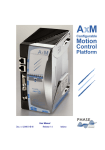
Artisan Technology Group is your source for quality new and certified-used/pre-owned equipment • FAST SHIPPING AND DELIVERY • TENS OF THOUSANDS OF IN-STOCK ITEMS • EQUIPMENT DEMOS • HUNDREDS OF MANUFACTURERS SUPPORTED • LEASING/MONTHLY RENTALS • ITAR CERTIFIED SECURE ASSET SOLUTIONS SERVICE CENTER REPAIRS Experienced engineers and technicians on staff at our full-service, in-house repair center WE BUY USED EQUIPMENT Sell your excess, underutilized, and idle used equipment We also offer credit for buy-backs and trade-ins www.artisantg.com/WeBuyEquipment InstraView REMOTE INSPECTION LOOKING FOR MORE INFORMATION? Visit us on the web at www.artisantg.com for more information on price quotations, drivers, technical specifications, manuals, and documentation SM Remotely inspect equipment before purchasing with our interactive website at www.instraview.com Contact us: (888) 88-SOURCE | [email protected] | www.artisantg.com AX4 Drive Application manual Ultrasonic IGBT PM Brushless motor drive series 4 AX AX5.7/11-2 AX12/16-2 AX04/08-3 AX8.5/14-3 AX17/35-3 Phase Motion Control S.r.l., Genova, Italy APPLICATION MANUAL 1 1/96 AXM1 - 2 Artisan Technology Group - Quality Instrumentation ... Guaranteed | (888) 88-SOURCE | www.artisantg.com AX4 Drive Application manual 1. Contents 1. CONTENTS .................................................................................................................................................................. 2 2. IN GENERAL............................................................................................................................................................... 3 2.1 TECHNICAL DATA .......................................................................................................................................................... 4 2.3 ELECTRIC DATA ............................................................................................................................................................. 5 2.4 THERMAL DATA ............................................................................................................................................................. 5 2.5 MECHANICAL FEATURES ............................................................................................................................................... 5 2.6 ENVIRONMENTAL DATA................................................................................................................................................. 5 3. MECHANICAL INSTALLATION ............................................................................................................................ 6 4. CONNECTIONS .......................................................................................................................................................... 8 5. EC NORMS AND INTERFERENCE PROTECTION........................................................................................... 16 6. COMMISSIONING ................................................................................................................................................... 18 6.1 ENCODER PHASING ...................................................................................................................................................... 18 6.2 TUNING ....................................................................................................................................................................... 21 7. DIAGNOSTIC ............................................................................................................................................................ 23 7.1 LEDS AND DIAGNOSTIC SIGNALINGS ........................................................................................................................... 23 7.2 ALARM HANDLING....................................................................................................................................................... 23 8. APPLICATION GUIDE ............................................................................................................................................ 26 8.1 INTRODUCTION ............................................................................................................................................................ 26 8.2 CHOICE OF THE TRANSMISSION AND OF THE OPTIMAL DRIVE ACCORDING TO THE APPLICATION .................................. 26 8.3 BRUSHLESS SYSTEM: OPERATIVE PRINCIPLES, DETAILS AND LIMITS ............................................................................ 27 8.4 CHOICE OF THE TRANSMISSION METHOD, OF THE TRANSMISSION RATIO, OF THE TYPE OF CONVERSION, OF THE KEYINGS AND THE COUPLINGS. .......................................................................................................................................... 28 8.5 CHOICE OF THE FEEDBACK METHOD ............................................................................................................................ 30 8.6 CONTROL OF THE ELECTRONICS AND MOTOR DIMENSIONING....................................................................................... 31 8.6.1 Motor limits ......................................................................................................................................................... 31 8.6.2 Electronic limitations .......................................................................................................................................... 32 8.6.3 Considerations about the electric supply ............................................................................................................ 32 8.7 RECURRING APPLICATION PROBLEMS .......................................................................................................................... 34 Phase Motion Control S.r.l., Genova, Italy 2 1/96 AXM1 - 2 Artisan Technology Group - Quality Instrumentation ... Guaranteed | (888) 88-SOURCE | www.artisantg.com AX4 Drive Application manual 2. General Data The AX4 drive is an electronic converter suitable for driving with high dynamic performance permanent magnet brushless servo-motors with low inertia with and with any polarity, up to a speed of 100,000 rpm. The converter is supplied by the three-phase mains, with or without an available neutral, at 220-240 and 380/440 V (+5% / -20%), 50-60 Hz. AX4 drive is supplied in three models for the 230 V supply voltage, with a nominal rms current of 5,7 , 12 and in tree models with a nominal rms current of 4, 8,5 and 17 A for 380-440 V supply voltage. Additionally, all AX4 drives are able to supply the rated peak current for 5 minutes or indefinitely with duty cycle up to 50%. The drives embody an innovative input stage characterized by limited inrush current, instantaneous drive availability and a low content of harmonics in line with the future IEC 555-3 norm; for this reason, the input power factor of the drives is unusually high and nears unity. AX4 is supplied with the ULTRACT brushless motor series, which use the last generation of FeNdB permanent magnets for high temperature, allowing operation up to 155°C. The motor is controlled with “six step” technology with a double control loop, current inside and speed outside; the current modulation is carried out at 16 kHz in order to obtain a noiseless functioning and a low current ripple and a 4 kHz current loop bandwidth. The motors, with a sinusoidal f.e.m., are equipped with a built-in optical encoder, which, apart from the standard channels used for speed control, is supplied with 3 commutation channels at 120 electrical degrees, with a cycle number equal to the motor polarity. The encoder signals (A and B) and the index (C) are available to the user transparently on the control connector for the coordination of the space and positioning loops. AX4 drive also supplies the stabilized power supply for the encoder on the motor and checks the motor thermal protection (PTC). The series is completed by the parallel AX-S drive module, which allows to use several parallel axes, sharing the energy flow among the axes. The AX-S module, moreover, incorporates a RFI filter, which allows compliance of the system (PDS) with one or more axes to the EMC IEC-EN 55011 norms Class B, equivalent to the more stringent VDE 871 norms, without individual drive filters. The control section for speed, current and all the other protections of the AX4 card are completely isolated from the power stage. In order to simplify the interface of the card with the electronics controlling the system, this section is supplied by the external control system, with any voltage between 20 and 30 Vdc. Such a configuration allows to control the drive with any electronic card without the need of optocouplers. The innovative control logic used in the drive allowed to eliminate the power electrolytic capacitors and the preload cycle at start-up; the card is immediately available with the presence of the power supply. The personalization of the feedback loops is carried out via scaling trimmers placed on a removable card which can be accessed from the front side of the drive. AX4 drive is supplied in a closed IP20 version with an internal fan and a thermal protection. The drive is protected from thermal overloads, blocked axis, overvoltage, low power supply, lack of phase and short circuit; such situations are signalled by LEDs. The alarm conditions are gathered in normal and critical alarm and are indicated on the control connector. In particular, the critical alarm drives a relay which can be used to cut off the power supply. The drive is supplied with a braking module and a dissipative element for full torque braking with a limited energy; for a braking cycle with considerable power an external resistor can be added. Phase Motion Control S.r.l., Genova, Italy 3 1/96 AXM1 - 2 Artisan Technology Group - Quality Instrumentation ... Guaranteed | (888) 88-SOURCE | www.artisantg.com AX4 Drive Application manual 2.1 Electrical Specifications AX5.7/11-2 AX12/16-2 AX04/08-3 Supply voltage Vac Input current Supply frequency Aac Nominal power Output rms current, cont. duty kW 2.2 4.5 Aeff 5.7 Output peak current (5 min. or < 50% duty cycle) Max. output voltage Aeff 11 PWM frequency Max. output frequency kHz 16 kHz 2.5 (standard scaling: 200 Hz) Efficency at nominal power output. 198-254 AX8.5/14-3 6 350-460 12 4 9 17 2.7 5.6 11.2 12 4 8.5 17 16.5 8 14 35 Hz 40 -100 Vac % Vin*.95 97.6 Vin*.95 96.5 96.9 Form power factor 96.5 95 0.85 Max. braking torque Effective braking power with internal resistance AX17/35-3 100% of the nominal torque W Phase Motion Control S.r.l., Genova, Italy 100 4 1/96 AXM1 - 2 Artisan Technology Group - Quality Instrumentation ... Guaranteed | (888) 88-SOURCE | www.artisantg.com AX4 Drive Application manual 2.2 Thermal data AX5.7/11-2 Power loss at rated current W Thermal capacity J 52 AX12/16-2 AX04/08-3 AX8.5/14-3 160 205 205 AX17/23-3 570 1400 2800 Thermal resistance junctions/environment K/W 1.1 .37 0.34 0.34 0.12 Thermal time constant s 1540 518 476 476 336 Cooling natural convection forced ventilation 2.3 Mechanical data AX5.7/11-2 Dimensions (L x P x H) Mass AX12/16-2 mm AX04/08-3 AX8.5/14-3 85 x 225 x 341 kg 2.4 2.4 Protection degree 2.4 AX17/23-3 182x225x 341 2.4 5.3 IP20 Vibration resistance 0.5 g in all directions Shock resistance 0.5 g in all directions 2.4 Environmental data ALL MODELS Operational temperature °C 0 / +40 Storage temperature °C -20 / +70 Humidity Height (1) 0 - 95% RH n.c. m 1000 (1) with nominal performances. Derate current by 5% every 100 m higher than 1000 m. Phase Motion Control S.r.l., Genova, Italy 5 1/96 AXM1 - 2 Artisan Technology Group - Quality Instrumentation ... Guaranteed | (888) 88-SOURCE | www.artisantg.com AX4 Drive Application manual 3. Mechanical installation The device is suitable for a wall-assembly, inside an electric cabinet and in non-dangerous environments. The dimensions of the drive and the hole positions for fastening are indicated in figure number 4-1. The installation place has to be dry, without vibrations and protected from the presence of conductive powder and steam. The maximum operational temperature is 40°C. For operation at lower temperatures, refer to the derating curve in Fig. 6. The drive must be installed vertically. It is also important to respect the minimum distances between each drive and the cubicle walls and the ones among different drives as in figure 3-b. figure 3-A - Mechanical obstructions and position of the fixing holes Dimensions [mm] AX17/35-3 a b c a1 b1 ∅ 85 341 225 50 325 5 182 341 225 100 325 5 Phase Motion Control S.r.l., Genova, Italy 6 1/96 AXM1 - 2 Artisan Technology Group - Quality Instrumentation ... Guaranteed | (888) 88-SOURCE | www.artisantg.com AX4 Drive Application manual figure 3-B - Criteria for the placement of the devices Phase Motion Control S.r.l., Genova, Italy 7 1/96 AXM1 - 2 Artisan Technology Group - Quality Instrumentation ... Guaranteed | (888) 88-SOURCE | www.artisantg.com AX4 Drive Application manual 4. Connections The exchange of the command and reference signals but also that of the feedback signals coming from the encoder is carried out via the two connectors placed on the front side of the device, Command Connector and Motor Sensor connector. On the front side ar and of the scaling trimmers (see figure 5-1) together with the power terminal board (with an extractable connector). Figure 5-2 illustrates the basic scheme for the connection of the AX4 drive, with an unidirectional speed reference and with an internal reference voltage (+10 V). In the following figures it is possible to see the connection schemes of the speed reference in the following cases: figure 4-b - internal reference voltage (+10 V) and bidirectional functioning figure 4-c - external reference signal and bidirectional functioning figure 4-d - external reference voltage and bidirectional functioning As for the choice of the drive protection fuses see the below selection table. No protection against overload is foreseen on the motor side, as an input for the contact of the motor thermal protection is already present on the Motor Sensor Connector. The tables 5.1, 5.2, 5.3 illustrate the functionality of each pin of the signal connectors and of each power terminal present on the drive. Phase Motion Control S.r.l., Genova, Italy 8 1/96 AXM1 - 2 Artisan Technology Group - Quality Instrumentation ... Guaranteed | (888) 88-SOURCE | www.artisantg.com AX4 Drive Application manual figure 4-A- Front view of the device Phase Motion Control S.r.l., Genova, Italy 9 1/96 AXM1 - 2 Artisan Technology Group - Quality Instrumentation ... Guaranteed | (888) 88-SOURCE | www.artisantg.com AX4 Drive Phase 1. 2. 3. 4. 5. 6. 7. 8. 9. 10. 11. 12. 13. 14. 15. 16. 17. 18. 19. 20. 21. 22. 23. 24. 25. Application manual Common mode inductance filter 1 1AX MOTOR CURRENT ENCODER A ENC. C (& PROXY) TACHO ENABLE SPEED REF SIGNAL GND AUX +5 V READY SPEED REF + 10V REFERENCE CURRENT LIMIT AUX +24 V NC PROXIMITY BYPASS RAMP ALARM NC ALARM NO AUX 0V ALARM COM CURRENT SEL SIGNAL GND ENCODER B NC NC 1 2 3 4 5 6 7 8 9 10 11 12 13 14 15 16 17 18 19 20 21 22 23 24 25 ENABLE SPEED REF + AUX 24V + BYPASS RAMP AUX 0V Connection table pag.14 - 15 CURRENT SEL. OFF = current ON = speed 1.1.3.2Moto r Sensor ENC. 1.1.3.2.1 ND 1.1.3.1.1 11 .3 .U 5 . 1.1.3.4.1.1 Motor 11 .3 .V 3 . 11 .3 .W 4 . 1.1.3.6.1 ND Motor 1. Use shielded cable only, with shield coverage > 85 % 6 11 .3 .S . 2. T BRBR+/DC+ Phase Motion Control S.r.l., Genova, Italy AUX 24V + LINE FILTER S Power cables longer than 20 meter may generate overvoltages on the motor and damage to the drives. Insert series inductance 1 H R 1.1.3.7GROUND BAR 10 Suggested circuit for motor brake relay. Zener 50V 5W 1/96 AXM1 - 2 Artisan Technology Group - Quality Instrumentation ... Guaranteed | (888) 88-SOURCE | www.artisantg.com AX4 Drive Application manual WARNING!! BEFORE CONNECTING EXTERNAL BRAKE DISCONNECT INTERNAL RESISTOR – LIVE CONTACTS AUX 0V figure 4-B- Connection scheme for the speed reference with internal reference voltage and bidirectional functioning. The input selection relay has to be mounted as near as possible to the drive figure 4-C - Connection scheme for the speed reference with external reference signal (+/-10V f.s.) figure 4-D - Connection scheme for the speed reference with external reference voltage and bidirectional operation Phase Motion Control S.r.l., Genova, Italy 11 1/96 AXM1 - 2 Artisan Technology Group - Quality Instrumentation ... Guaranteed | (888) 88-SOURCE | www.artisantg.com AX4 Drive Application manual TABLE 2.4-A COMMAND CONNECTOR - FUNCTIONALITY AND SIGNAL DESCRIPTION N. Pin Name CONN. ON CARD - 25 PIN D-Type CANNON, REMOVABLE FEMALE Type Function Signal description 1 MOTOR CURRENT Analog output Instant indication of the motor current The output signal refers to the Pin 7. The current can be obtained from the formula: Im = Ipk/9V. Output impedance: 10 kOhm 2 ENC A Digital output Channel A encoder (reversed) Signal open collector 24V, 20mA. See note 2. 3 ENC C (& PROXY) Digital output Encoder index (logic AND between the Proximity input and zero encoder) Signal open collector 24V, 20mA. See note 1 and 2. 4 TACHO Analog output Indication of motor speed The output signal refers to the Pin 7. The speed can be obtained from the ratio: 850mV / 1000rpm Output impedance: 10 kOhm 5 ENABLE Digital input Drive enable The drive is enabled for voltages from 14 to 30V compared to the Pin 7. Input impedance: 1 kOhm Disabling the drive the motor is free at any speed. 6 SPEED REF- Analog input Negative of reference +/10V input If it is not used connect to the Pin 7. A positive voltage value corresponds to the clockwise rotation of the shaft seen from the torque side. Input impedance: 10 kOhm 7 SIGNAL GND 0V analog signals 8 AUX +5V Auxiliary supply output 9 READY - Digital output NOR of protection logic output Signal open collector 24V, 20mA. See note 2. 10 SPEED REF+ Analog input Positive of reference +/10V input If it is not used connect to the Pin 7. A positive voltage value corresponds to the anticlockwise rotation of the shaft seen from the torque side. Input impedance: 10 kOhm 11 10V ref Analog output Reference voltage Stabilized voltage output. Max current: 5mA Regulation: +/-1% 12 CURRENT LIMIT Analog input Dynamic limitation of current/torque It allows the variation of the current/torque limit via an analog input. Range: 0-10V = 0-100% If it is not connected the limit is 100%. The internal pull-up is 15V, 10 kOhm. 13 AUX +24V Auxiliary supply Aux supply for regulation circuits Voltage: 24-30 V referred to Pin 19. Supply current: 600mA. 14 NC Max current: 100mA Regulation: 0/+200 mV Phase Motion Control S.r.l., Genova, Italy 12 1/96 AXM1 - 2 Artisan Technology Group - Quality Instrumentation ... Guaranteed | (888) 88-SOURCE | www.artisantg.com AX4 Drive Application manual TABLE 5-1 COMMAND CONNECTOR - FUCTIONALITY AND SIGNAL DESCRIPTION N. Pin CONN. ON CARD - 25 PIN FLOAT CHAMBER CANNON, EXTRACTABLE FEMALE Name Type Function Signal description 15 PROXIMITY Digital input Input for suppression of the encoder zeros High signal for voltages from 14 to 30 V in comparison to the Pin 7. If it is not connected it is recalled to 0 internally. See note 1. 16 BYPASS RAMP Digital input Ramp clear If enabled (voltages from 14 to 30 V in comparison to the Pin 7) it clears the ramp. Input impedance: 22 kOhm. 17 ALARM NC Alarm relay Normally closed contact Contact isolated from power and signal. Max current: 1A Max voltage: 250V 18 ALARM NO Alarm relay Normally opened contact Contact isolated from power and signal. Max current: 1A. Max voltage: 250V. 19 AUX 0V 0V auxiliary supply Internally connected to the Pin 7. To be used only for the auxiliary supply. 20 ALARM COM Alarm relay Common on relay contacts 21 CURRENT SEL Digital input Regulation selection of current/speed High: speed regulation. Low: current regulation. High signal for voltages from 14 to 30 V in comparison to the Pin 7. Input impedance: 10 kOhm 22 SIGNAL GND 23 ENC B 24 NC 25 NC Digital output Channel B denied encoder Signal open collector 24V, 20mA. See note 2. Note 1 - Using the circuit for the suppression of the encoder zeros When there is the presence of a simple mechanical transmission system, where the transmission ratio between the motor shaft and the activated axis is an integer, the signal of the motor encoder can be converted into a position signal of the activated axis. If R is the transmission ratio between the motor and the axis, in order to have the inidcation of the shaft position it is necessary to eliminate the R-1 zeros of the encoder signal. To this purpose it is sufficient to use a sensor with a low resolution (for example a proximity) which is able to supply a signal differnt from zero only in connection with the zero angular position of the activated axis. This function is enabled when the jumper S10 is taken away from the card. The proximity signal is taken by the Pin 15 of the Command Connector and the zero suppression circuit carries out a logic AND between the proximity signal and the encoder zeros. The operation result, equal to 1 in connection with the useful zero, is available on the Pin 3 of the Command Connector. Note 2 - Open Collector Signal he drive is not provided with an internal pull-up resistance. If it is necessary use an external one connected to a potential not higher than 30 V. Phase Motion Control S.r.l., Genova, Italy 13 1/96 AXM1 - 2 Artisan Technology Group - Quality Instrumentation ... Guaranteed | (888) 88-SOURCE | www.artisantg.com AX4 Drive Application manual TABLE 2.4-B MOTOR SENSOR CONNECTOR: FUNCTIONALITY AND SIGNAL DESCRIPTION Card Conn. Pin CONN. ON CARD - 15 PIN D-Type CANNON, REMOVABLE MALE CONN. TO THE ULTRACT (*) MOTOR - TYPE IPT 06A-12-14S, MIL C 26482 Motor Terminal Name Type Function Signal Connect Block description or Pin 1 A 2 GND+PTC 0V 2 -- -- HALL 1N Digital input 3 P 5 HALL 1 4 C 4 5 D 6 Digital input Hall sensor phase 1 denied Hall sensor phase 1 Square wave 5V Square wave 5V HALL 2 Digital input Hall sensor phase 2 Square wave 0-5V 11 HALL 3 Digital input Hall sensor phase 3 Square wave 5V 0- E 1 AUX +5V Auxiliary supply 7 F 7 ENC A+ Digital input Channel A encoder Square wave 5V 0- 8 B 15 PTC Digital input Motor protection 9 H 9 ENC I- Digital input Denied encoder index Square wave 5V 0- 10 -- -- HALL 2N Digital input -- -- HALL 3N Digital input 12 J 8 ENC A- Digital input Square wave 5V Square wave 5V Square wave 5V 0- 11 Hall sensor phase 2 denied Hall sensor phase 3 denied Channel A denied encoder 13 K 13 ENC B- Digital input Channel encoder Square wave 5V 0- 14 L 10 ENC I Digital input Encoder index Square wave 5V 0- 15 M 14 ENC B Digital input Channel B encoder Square wave 5V 0- (*) NOTE: As for motors different from the ULTRACT series, see figure Phase Motion Control S.r.l., Genova, Italy 00- thermal B denied 00- 6-a. 14 1/96 AXM1 - 2 Artisan Technology Group - Quality Instrumentation ... Guaranteed | (888) 88-SOURCE | www.artisantg.com AX4 Drive Application manual TABLE 2.4-C POWER CONNECTIONS MORS. ON CARD - PHOENIX PC4/10-ST 7.62 10 CONTACTS - REMOVABLE FEMALE CONN.TO THE ULTRACT MOTOR - MS/MIL C 5015 TYPE CVB 06A 22-22S Terminal Description ULTRACT Pin connector Wire color in the ULTRACT motor U Motor phase U B Red V Motor phase V A Blue W Motor phase W C Yellow R Supply phase R --- --- S Supply phase S --- --- T Supply phase T --- --- BR- Resistance connection for external braking --- --- Resistance connection for external braking --- --- BR+ (Positive DC bus ) DC- Negative DC bus --- --- GND Power circuit mass D Yellow-green Phase Motion Control S.r.l., Genova, Italy 15 1/96 AXM1 - 2 Artisan Technology Group - Quality Instrumentation ... Guaranteed | (888) 88-SOURCE | www.artisantg.com AX4 Drive Application manual 5. EC norms and interference protection Brushless drives of the AX-4 series are components for PDS (Power Drive System), designed in accordance with the EMC 89/336/EEC and LVD 93/68/EEC norms and in particular with the EMC IEC-22G-21/CDV norm. They are specified for the application Fields 2,3. As Components the AX-4 drives comply with the IEC 1000-4-2 (IEC 801-2) and IEC 1000-4-4 (IEC 801-4), without any accessory or protection. The above mentioned IEC 22G norm specifies an electromagnetic interference limit for the active system and not for the component (it would not be possible in any case). As for applications similar to the reference one, the single or multi-axes coupling with the AX-S filtrated supply module, that is with the filter SHAFFNER FN351/25/33 or something equivalent, with up to 100 meters of shielded-conductor cable between the drive and the motor, allows the active system (PDS) to satisfy the requirements of the IEC-EN 55011 norm Class B, equivalent to the more urgent VDE 871 norms. If required, type test certificates are available. With these limits, the EC marking, even though it is not necessary, has been present on the AX4 series starting from 1.1.1996. Operative advice In order to minimize the electromagnetic interference, the signal cables have always to be shielded; the use of a shielded cable is suggested also for the power connections. As for the shields and ground connection see the figure 6-1. In order to reduce the interferences caused by the motor cable and the induced noises in the encoder connection cable, such cables have not to be longer than 20 meters. Such length is necessary also for the protection of the drive itself. It is important that the power wiloop is inserted in wireways different from the signal and supply one and that any cross between the power and signal cables is carried out at right angle. It is necessary to have always a mass cable between the motor and the drive, with a layout similar to the one belonging to the power cables. If the plant foresees the use of sensitive instruments (for example analog non preamplified transducers, load cells, thermocouples etc.) keep the maximum distance between the instrumentation ground and the power one. As the high voltage caused by the drive is partially coupled on the ground conductor, it is normal that a weak current with a high voltage crosses the conductor itself; because of this it could be impossible to use high sensitivity differential switches. For the same reason, the ground cable may represent a duct carrying the electromagnetic interference to the other parts of the plant; as a consequence, it is useful to remove the small signal cables from the ground cable even in the upper part of the drive. NOTE: as specified in the EMC IEC-22G-21/CDV norm, the AX4 drives are not destined to be used in a domestic environment and they may cause some interferences to the radio and television receptions. Phase Motion Control S.r.l., Genova, Italy 16 1/96 AXM1 - 2 Artisan Technology Group - Quality Instrumentation ... Guaranteed | (888) 88-SOURCE | www.artisantg.com AX4 Drive Application manual figure 5-A - Ground connection diagram Phase Motion Control S.r.l., Genova, Italy 17 1/96 AXM1 - 2 Artisan Technology Group - Quality Instrumentation ... Guaranteed | (888) 88-SOURCE | www.artisantg.com AX4 Drive Application manual 6. Commissioning 6.1 Encoder phasing IMPORTANT: The Ultract motors supplied for the use with AX4 drives are factory set and therefore the phasing has not to be carried out except after a possible replacement of the encoder. The following procedure has therefore to be used only in such a case or with the use of motors not belonging to the ULTRACT series. In order to allow a correct functioning of the drive it is necessary that the Hall effect encoder/sensors group mounted on the motor is located in a precise position consideloop the windings of the motor phases. Normally the encoder positioning, or phasing, is carried out with the motor construction and therefore no intervention is required to the user. Anyway, should this operation be necessary, act as follows: 1. Disengage the axis letting the motor free to rotate 2. Open the rear motor cap and loosen the screws of the encoder stator 3. Supply the drive both for power and signal and enable the drive without reference, with a current control. 4. Press the PHASE SET button and keep it pressed; the motor takes a direction and blocks itself. In this condition, if the encoder position is a wrong one, the two LD3-LD4 leds light up simultaneously 5. Rotate by hand the encoder body observing the LD3-LD4 leds till they change their condition simultaneously 6. Block the encoder screwing the screws with a 0.2-0.5 Nm clamping torque and depress the PHASE SET button 7. Close the rear cap screwing the screws with a 5 Nm torque We suggest to carry out the encoder phasing with the highest possible care. The max accepted error is 1 degree, equal to 0,5 mm on the encoder perimeter. NOTE 1: Shold the phasing be impossible, that is the motor does not rotate uniformly in the current loop, control the sequence of the motor phases and of the Hall ducts as in figure 7-1. NOTE 2: If, after the phasing, the motor operates regularly in the current loop but it presents a runaway effect in the speed loop, control the sequence of the encoder signals A,B and C as in figure 7-2. Phase Motion Control S.r.l., Genova, Italy 18 1/96 AXM1 - 2 Artisan Technology Group - Quality Instrumentation ... Guaranteed | (888) 88-SOURCE | www.artisantg.com AX4 Drive Application manual figure 6-A - Motor phase sequence - Hall probes Phase Motion Control S.r.l., Genova, Italy 19 1/96 AXM1 - 2 Artisan Technology Group - Quality Instrumentation ... Guaranteed | (888) 88-SOURCE | www.artisantg.com AX4 Drive Application manual figure 6-B- Encoder signal sequence - Hall sensors Phase Motion Control S.r.l., Genova, Italy 20 1/96 AXM1 - 2 Artisan Technology Group - Quality Instrumentation ... Guaranteed | (888) 88-SOURCE | www.artisantg.com AX4 Drive Application manual 6.2 Tuning The following tuning trimmers are available on the drive. They are located on a removable personality card: NAME DESCRIPTION RANGE FACTORY STANDARD SCALING RAMP UP Acceleration ramp time for a clockwise rotation Deceleration ramp time for an anti-clockwise rotation 0-30 s 0s RAMP DOWN Deceleration ramp time for a clockwise rotation Acceleration ramp time for an anti-clockwise rotation 0-30 s 0s DER. GAIN Derivative feedback gain (speed loop) MAX. SPEED Speed range set 0-100% 0% OFFSET Offset speed +-10% n max 0% I MOTOR Current limit 0-100% set for the value of the size max current PROP. GAIN Proportional gain (speed loop) set for the standard motor foreseen for the size of drive 1) INT. GAIN Integration gain (speed loop) set for the standard motor foreseen for the size of drive 1) set for the standard motor foreseen for the size of drive 1) 1) The factory setting of the feedback loop provide moderate loop quality for load inertia ranging 0 to 5 times the motor inertia, but they are not optimized for a fast response time which requires a good knowledge of the mechanical system. The integrator can be enabled or disabled with the INT GAIN ON/OFF jumper. In a new application, adjust the feedback loop parameters with the following trial and error procedure: 1. Disable the integrator by removing the INT GAIN jumper 2. Enable the drive with zero reference, or better, with an adjustable asquare wave generator set at ~ 1Hz. 3. Increase progressively the proportional gain until the system starts becoming unstable 4. Enable the integrator and increase it until the the overshoot becomes unacceptable 5. Increase the derivative gain until the overshoot disappears. NOTE: Transplanting purposes). the personality card to a new drive allows transplanting all the settings (for maintenance Phase Motion Control S.r.l., Genova, Italy 21 1/96 AXM1 - 2 Artisan Technology Group - Quality Instrumentation ... Guaranteed | (888) 88-SOURCE | www.artisantg.com AX4 Drive Application manual Phase Motion Control S.r.l., Genova, Italy 22 1/96 AXM1 - 2 Artisan Technology Group - Quality Instrumentation ... Guaranteed | (888) 88-SOURCE | www.artisantg.com AX4 Drive Application manual 7. Diagnostic 7.1 LEDs and diagnostic signalings On the front side of the drive there are 14 signaling leds. The meaning of each LED is indicated in the TABLE 8.2-1. 7.2 Alarm handling Here you can find a description of the measures to be taken in case an alarm signal appears. • The SUPPLY Led is not lit Check if the power circuit is supplied. • The AUX=OK Led is not lit Check the presence of the auxiliary supply. • The TORQUE Led is not lit Check the presence of the enabling command on the Command Connector. • One of the ENC A, ENC B, ENC C Leds does not light up while the motor is rotating or it remains always lit Deenergize the power section, rotate by hand the motor shaft controlling the presence of the signals of the encoder channels on the Motor Sensor Connector and their commutations. • The UV Led is lit There has been a voltage decrease on the DC bus. Check the value of the line voltage. The Led lightning does not block permanently the drive, but the message is stored. In order to reset the alarm it is necessary to stop and start again the auxiliary voltage. In case the undervoltage situation lasts for a too long time, there is a breakdown of the capacitors on the bus, with the possibility of a motor stopping. In this case it is necessary, when the right main voltage has been reset, to disable and enable the drive to start it again. In undervoltage conditions lasting more than 2 ms, there is the commutation of the alarm relay. • The OV Led is lit There has been a voltage increase on the DC bus. Check the value of the clamp resistance. The Led lightning does not block permanently the drive, but the message is stored. In order to reset the alarm it is necessary to stop and start again the auxiliary voltage. In overvoltage conditions lasting more than 2 ms, there is the commutation of the alarm relay. • The HALL CODE Led is lit The card has detected an error on the sequence of the Hall commutation signals. Stop supplying the power section, then, rotating by hand the motor shaft, control the presence of the duct signals on the Motor Sensor Connector. The Led lightning does not block the drive permanently, but the message is stored. In order to reset the alarm it is necessary to stop and start again the auxiliary voltage. - The ENC FAIL Led is lit Phase Motion Control S.r.l., Genova, Italy 23 1/96 AXM1 - 2 Artisan Technology Group - Quality Instrumentation ... Guaranteed | (888) 88-SOURCE | www.artisantg.com AX4 Drive Application manual The card detects the lack of the encoder signal (see the note). Check the presence of all direct and denied encoder signals on the Motor Sensor Connector. If all the signals are correct, check the ground connections. The SH C Led is lit. Short circuit signal in the wiring or motor, ground fault on motor side. Apart from the short circuit, it can be activated by: 1. wrong encoder phasing; 2. poor connection of the motor ground to the drive ground, 3. radio interferences in the supply or in the cabinet; 4. too long wiring with an excessive capacity. In the last case, adding an inductance on the output cables generally solves the problem. NOTE: In order to use motors without encoder channel (only in current loop), close jumper S7. TABLE 7.2-A SIGNALING LEDS LED Color Normal condition Alarm Meaning Memory and block Memory without block READY Green Lit The drive is ready SUPPLY Green Lit Power supply OK ENC. B Yellow Blinking* Channel B encoder OK ENC. A Green Blinking* Channel A encoder OK ENC. C Red Blinking* Encoder index OK TORQUE Green Lit** Card enabled AUX=OK Green Lit Aux. supply OK UV Yellow Out Undervoltage X OV Yellow Out Overvoltage X HALL CODE Yellow Out Lit Wrong Hall sensor code X ENC FAIL Red Out Lit Failure on the encoder X TH DRIVE Red Out Lit Thermal protection, drive X TH MOTOR Red Out Lit Thermal protection, motor X SH. C Red Out Lit Short circuit X * with a rotating motor Phase Motion Control S.r.l., Genova, Italy 24 1/96 AXM1 - 2 Artisan Technology Group - Quality Instrumentation ... Guaranteed | (888) 88-SOURCE | www.artisantg.com AX4 Drive Application manual ** with enabling command ON Phase Motion Control S.r.l., Genova, Italy 25 1/96 AXM1 - 2 Artisan Technology Group - Quality Instrumentation ... Guaranteed | (888) 88-SOURCE | www.artisantg.com AX4 Drive Application manual 8. APPLICATION GUIDE 8.1 Introduction The drives based on brushless motors with rare earths permanent magnets are considered to be the motors with the highest dynamic performance and with the highest specific torque and power available on the market. The progressive replacement of the traditional DC, inverter or hydraulic drives with brushless motors on the automatic machines allows to improve the obtainable performances, above all as far as the cycle time, the tracking and actuation precision, the dynamic and the operating system are concerned. This changing in the motorization, anyway, requires the knowledge and the correct use in the system or in the activated machine of the capacities of the new drives; the simple change of the old motorization with new brushless motors can cause big problems on those machines which are not designed for the available dynamic and sometimes it can also decrease the quality of the system instead of improving it. The guide has been designed in order to supply an operative instrument for the first commissioning of the application on the side of users who are not familiar with these motors and their performances, in order to determine immediately the practicability of each new task. In order to optimize completely the important applications it is advisable anyway to refer directly to the supplier. 8.2 Choice of the transmission and of the optimal drive according to the application At the basis of every application there is a right choice of the system parameters, which have to be definied so that it can be possible to use in an excellent way the remarkable features of the modern brushless drives, which sometimes are not fully understood. The range of choices derives from the fact that a brushless drive is not a simple motor but on the contrary a complex drive system with a high feedback degree; therefore it is much more flexible and sofisticated. Conceptually speaking, the brushless motor, in fact, is much more similar to the membrane of a loudspeaker than to a conventional motor; it is able to answer in a very short time to any electric command, but, as for the loudspeakers, the quality of the result depends much more on the control system than on the motor itself. The choices made by the designer of the brushless motor system are made both on a mechanical and electronic basis; in order to choose the best solutions it is necessary to know the operative principles and the capacities offered by the modern brushless drives. In particular, the basic choices present in every system are: • mechanically: Choice of the transmission method, of the transmission ratio, of the type of motion conversion, of the fits and the couplings. • electronically: Choice of the feedback strategy, of the sensor type and number, of their disposition, of the control and synchronizing devices, of the method for the command transmission. In the following paragraphs it is possible to find a list of some criteria used to direct these choices according to the application. Phase Motion Control S.r.l., Genova, Italy 26 1/96 AXM1 - 2 Artisan Technology Group - Quality Instrumentation ... Guaranteed | (888) 88-SOURCE | www.artisantg.com AX4 Drive Application manual 8.3 Brushless system: operative principles, details and limits Each brushless drive is made up of an electronic amplifier, a motor and at least a feedback sensor. The motor acts only as a power generator; the effect produced by such power is measured by the sensor, the electronics makes a comparison between the effect and the desired result and changes the power generated by the motor in order to reach the desired result. For example, in an application where a constant speed is needed, the electronics increases gradually the torque supplied by the motor till the sensor does not detect a speed equal to one required. If the load increases suddenly, the speed decreases, the sensor detects such decrease and the electronics increases the torque supplied so that it is possible to bloop the motor back to the speed set at the beginning. As a consequence: 1. the speed accuracy is almost independent of the load and completely independent of the motor, but it depends only on the sensor quality and on the electronic regulations; 2. the time used to react to the load variations depends critically on the speed for the acquisition of the sensor signal and on the electronic regulation. The modern brushless systems may reach reaction times of milliseconds, and therefore they offer high quality performances; such performances, anyway, are often limited by the mechanical answeloop times of the system; in order to use the new available performances it is necessary an evolution of the mechanical project of the conventional applications. For instance, consider a drive with a constant speed like the one mentioned in the above example. If the motor is coupled to the load with a timing belt, there is a certain degree of elasticity between the motor and the load axis. If, as assumption, the load has a significative inertia, and if the first moments of the motion are analyzed, it is possible to state the following sequence: 1) the electronics supplies the current and the motor starts to rotate, loading the system elasticity and avoiding to move the load inertia; 2) if the electronics is fast, it is able already in this phase to detect that the motor has reached a speed higher than the one foreseen and it decreases the torque; 3) at the same time, the belt stretches and slows the motor, reducing its speed; 4) the combined effect of the torque reduction and of the load acceleration via the belt makes the belt tension decrease; 5) the electronics notices the speed reduction and increases the motor torque, starting a new cycle. We are therefore in presence of a swinging phenomenon, where the motor and the load increase and decrease their speed continuously. It is possible to notice a vibration and a high noise. A superficial observer would ascribe this phenomenon to a noisy motor; such idea could be supported by the fact that sometimes the noise can be eliminated changing the motor with another of lower quality, that is with a slower answeloop capacity. On the contrary, analyzing what stated above it is clear that: 1) the phenomenon has to be ascribed to the disagreement between the system elasticity and the electronic regulation; practically the motor reacts with a speed equal to the reaction time or to the load setting time of the mechanics; 2) the possible solutions are: • decreasing the system elasticity and therefore accelerate the load setting time of the mechanics, for example replacing the belt with gears; • slowing down the answeloop time of the motor/electronics system, renouncing to a part of the possible performances. The second solution degrades the machine quality, because it increases the time used to reach the position or the speed desired, that is it decreases the motor possibility to react to sudden loads and interferences. It is important to underline that the motors of lower technology, that is bigger and slower ones, meet the lack of speed with a considerable inertia; the brushless motor, on the contrary, having a reduced inertia, must be activated, in some cases, with a sufficient speed in order to avoid a high performance degradation. On the basis of the mentioned example, it is easy to understand the behaviour of a brushless system with mechanical instruments, for example a machine key; for this reason the best quality brushless motors are designed with a smooth shaft and they have to be coupled at interference via a keying device. The only flexible joints suitable to the dynamic are those with a metallic bellow. All these considerations rvation: Phase Motion Control S.r.l., Genova, Italy 27 1/96 AXM1 - 2 Artisan Technology Group - Quality Instrumentation ... Guaranteed | (888) 88-SOURCE | www.artisantg.com AX4 Drive Application manual while the traditional motorizations (motors CC and PM) were, with their inertia, the limit to the dynamic performances of the activated system, the higher performances of the brushless motors often let the dynamic limit of the system to be determined by the mechanics which is activated. Therefore in this case it is much more important to understand and control the system mechanics in order to realize efficient applications. From the above mentioned example it is possible to draw some observations: • the accuracy does not depend on the motor but on the sensor; • the answeloop speed and therefore the ability to follow the reference with accuracy depends critically on the stiffness of the transmission; • the noise problem, which sometimes is underlined by the system, does not depend either on the motor or on the electronics but on a “primordial” mechanics as compared to the system performances; the same mechanics, in fact, would not have caused any problem using a slower motor with a less modern technology; • the motor noise is caused by the continuous accelerations and brakings; in such conditions it is possible that the motor overheats, not ascribing the cause to its insufficient dimensions. As the system dynamic is a basic feature for the dimensions of the motors, it is important to define it more precisely. The dynamic is made up of two elements: • the ability to accelerate the load at different levels, which depends exclusively on the ratio torque/moment of inertia of the motor; such feature is sometimes defined as “passing belt with big signals”; • the passing control belt, which is so much high as short is the time used by the drive feedback loop to stabilize itself on the desired value. This parameter depends critically on the mechanics, because in order to realize a steady system it is not possible to stabilize the electronics before a period equal to 2-3 times the period needed to damp the swingings of the mechanics of the activated system. For example, you want to realize the axis of a gnawing machine with 10 strokes per second in positions which are continuously updated by a fast numeric control. If the transmission system between the motor and the piece (joint, screw, holder etc.) has a frequency of mechanical resonance equal to 50 Hz and it swings in a period of 20 msec., it will not be possible to stabilize the system in less than 3 x 20 msec., that is 60 msec. At this point there are only 40 msec. left in the total cycle for the stroke and the whole motion. The application is quite impossible, independently of the motor used. On the contrary, if there is an improvement of the mechanics, with stiffer joints, with bigger screws etc. till reaching a frequency of mechanical resonace of 100 Hz, it is possible to have a drive stabilizing period of 30 msec. Leaving 70 msec for the stroke and the motion. In this case the application starts to be realizable. 8.4 Choice of the transmission method, of the transmission ratio, of the type of conversion, of the keyings and the couplings. The dimensions of a brushless motor, like all the others, are based on the supplied torque and not on the given power. In all applications, therefore, a low motor speed corresponds to a low specific power and to a low gain. It has to be underlined that the brushless motor has no minimun speed (the speed depends only on the sensor used; there are applications whose axis speed is 1 revolution/year); as a consequence it is logic to act on the transmission to allow a high rotation speed of the motor only when it is important to minimize the motor dimension (e.g. with electric traction) or to maximize the gain; on the contrary it is not a logic solution for the costs and the dynamic performances of the system. Anyway, all applications where the motor acts directly on the load, are characterized by the highest passing control belt, because there is the maximum transmission stiffness and because these applications are able to offer the best position or following accuracy in shorter times. Before starting with the selection of the right drive for a specific system, it is necessary to know the type of mechanical transmission which can be used. The most common transmissions are the following: • • • • Rotation-rotation conversion: timing belt; reducer with helical wheels and parallel axes; cycloid and epicycloid reducer; Harmonic Drive™; Phase Motion Control S.r.l., Genova, Italy 28 1/96 AXM1 - 2 Artisan Technology Group - Quality Instrumentation ... Guaranteed | (888) 88-SOURCE | www.artisantg.com AX4 Drive Application manual • tangent screw reducer or Gleason. • • • • Rotation-rectilinear motion conversion: timing belts; sphere screw; pinion-rack; metallic band. For any transmission system, the load parameters are compared to the motor axis as follows. If n = transmission ratio (ratio between the motor and the load speed, in the case of a conversion from rectilinear motion rad/m), you will have: Motor torque = Torque (push) to the load/n Motor speed = Load speed x n Load inertia brought to the motor axis = inertia (or mass) load/n² Among all the listed transmissions, the first ones, which are the less expensive, are the slowest and they allow only medium-low passing belts (lower than 10 Hz, always using a belt with a low stretching degree); for the same reason, it is important to avoid the ratios which make the load inertia brought to the motor axis too much higher than the motor one. The belt transmissions can not be applied for positioning applications with cycles lower than one second. The gear reducers represent a perfect solution only when their difference is a value lower than the accuracy required by the system; the best reducer (the most expensive too) is always epicycloid; there are special series of cycloid and epicycloid reducers designed on purpose for servo controls, where the difference at the output axis is contained in 10-15 arc minutes. Such reducers are the only one that can be used in applications with passing belts higher than 10 Hz. The reducers “servo series” are foreseen to be coupled directly to the motor with keying device, without a key machine. The Harmonic Drive™ reducer is another reducer designed for the positioning. It has no overall dimensions, high ratios and low difference. The angular stiffness is not very good and the obtainable passing belt is about 10 Hz. Because of its limited energetic efficency, it should be used only for positioning. Another cathegory is presented by the tangent screw reducers. Such reducers are not suitable for the application with speed changing motors. The screw reducers, in fact, have a gain which decreases with the speed and the strong friction of the first leaving, with the result that the systems are ineffective with a low speed while there is the development of a high reducer consuption. As for the linear conversion, the sphere screws offer a good solution till about 1 m/s, allowing to avoid any other reduction. For very long movements it is necessary to control the flexion and torsional stiffness of the screw, which may represent the limit to the system belt. Longer movements are carried out with racks, which have always a significative difference and limit the belt to a few Hz. The classical systems for the recovery of the difference are not much effective inside the control systems, and sometimes they are harmful too. Fast and accurate movements can be obtained with metallic bands. This technique, which is not much spread and therefore not standardized, is able to reach excellent performances in the control of small masses (some kilos). The use of linear motors is the best solution to obtain the best performances with a rectilinear motion. To select the most suitable method and transmission ratio for a specific application it is necessary to distinguish between two application types: 1. Power applications, the motor supplies power to a process (mandrels, traction, windings etc.), where the dynamic performances are marginal, the transmitted power is significative, the motor cost is an important fraction of the system cost; 2. Positioning applications or rapid cycle applications (electronic cams), the majority of the energy is used to accelerate, to brake and to position the objects in short times and with a more or less high accuracy. Traditionally, the two above mentioned categories are referred to respectively as mandrels and axes. In the first case, the dynamic is often not important, therefore it is possible to use cheap reducers and, as the powers used are often relevant, a mechanical transmission with a reduction phase is normally useful. In order to choose the best transmission ratio, we have to consider that the dimension and the cost of the motor, till the speed is lower than 4000 RPM, decrease in a linear way with the transmission ratio. On the contrary, the cost of the transmission increases step by step according to the number of gear torques or pulleys; economically speaking, it is possible to find the best solution only in a few particular cases, precisely: • with a direct outlet; Phase Motion Control S.r.l., Genova, Italy 29 1/96 AXM1 - 2 Artisan Technology Group - Quality Instrumentation ... Guaranteed | (888) 88-SOURCE | www.artisantg.com AX4 Drive Application manual • with the maximum obtainable ratio with just one reduction torque; • with the maximum obtainable ratio with two reduction torques etc. The economic optimization, in this case, is carried out checking these points and adding the obtained costs of the motors to the ones of the reducers. On the contrary, as for the applications with a high dynamic (axes) the situation is completely different. If the torque required in the drive cycle is dominated by the inertial torque both of the motor and of the load, it is clear that increasing the reduction ratio there is a decrease of the importance of the load inertia and an increase of the motor one. It is possible to state, therefore, that, for an application where the torque given is exclusively inertial, the reduction ratio able to make the load inertia, compared to the motor axis, equal to the motor inertia (inertial coupling) is the one the minimum torque given corresponds to (as a consequence the motor is smaller). For this reason, the inertial coupling has been considered for a long time the only correct coupling system. Such rule, on the contrary, is only a useful indication. In fact, the minimum dimensioning of the motor, consideloop that the cost of a reducer is usually the double of the motor one, does not correspond to the cheapest application dimensioning. If we consider also that the application dynamic depends on the elasticity and on the differences of the transmission, it is not logic to optimize the ratio taking into consideration only the motor. In general, it is possible to state that: • any transmission ratio higher than the inertial ratio is not correct; • the best ratio is always lower or equal to the inertial one, and it is obtained consideloop the motor and reducer costs; • high ratios present always a passing belt and a lower degree of accuracy (with a higher energetic consumption) than what can be obtained with lower ratios. These considerations explain the today attempt to eliminate the reducers in order to operate in a direct way. When the load inertia is higher than the motor one, it is necessary to be particularly careful, because the motor inertia is no more able to carry out a stabilizing action on the possible mechanical resonances of the system. As a consequence, the mechanical system in these applications has to be of high quality, stiff and without differences, and the coupling without machine key (that is with keying device). Operating with a direct traction, it is necessary to check the torsional stiffness of the system. In particular you have to consider also the torsional elasticity of the motor shaft, which is significative in the case of motors longer than any other size. The series of brushless motors are superimposed, so that the same torque can be obtained with a long and narrow motor or with a short and stocky one. For this reason: • long motors have a minimum moment of inertia and they have to be used for high accelerations with low inertia loads; • stocky motors have a maximum torsional stiffness and they have to be used with loads whose inertia is sometimes higher than the motor one. Here is the formula expressing the torsional stiffness of a shaft whose diameter is D and whose length is L; the shaft is made of steel: π D4 Sm = • • 78.5 • 10 9 32 L while the first sequence of torsional resonance of a load with inertia JI connected to an axis with torsional stiffness Sm is given by the following formula: F1 = S 1 • m (2 • π ) Jl If you decide to use an application with short times and with a high load inertia, it is necessary to set a proof of the first mechanical resonance of the system. 8.5 Choice of the feedback method The drive system can be set in three different operative ways: • torque control (the speed depends on the load); • speed control (the torque depends on the load); • position control Phase Motion Control S.r.l., Genova, Italy 30 1/96 AXM1 - 2 Artisan Technology Group - Quality Instrumentation ... Guaranteed | (888) 88-SOURCE | www.artisantg.com AX4 Drive Application manual The first operative way is the easiest and can be always used when it is necessary to control a power (winders/unwinders, textile machines and machines for the band processing, etc.). The torque control is generally steady (the steadiness does not depend on the load) and fast (passing belt >300 Hz), but not much accurate (~10%). In the multi-axes applications with very fast and modern CN, with an adaptive control or with variable parameters, it is necessary to set the drive in torque control and to assign the closing of the other loops to CN. As for the torque control the drive regulates the motor current; the motor therefore is also a transducer. No external sensors are necessary. The sensor on the motor can be semplified only to the Hall system for the motor commutation. The speed control is the most traditional. It usually uses an integrative term so that the speed error is limited to the system offsets. In the digital drives, the speed loop is obtained by the space loop (see). The position or space control is carried out only by digital drives (AX-V). In this operative way, the speed error is limited to a few calculations of the sensor, that is in the case of an encoder with 4096 pulse/revolutions, 1/16,000 of a revolution. In this operative way it is also possible to synchronize several axes (electrical axis). 8.6 Control of the electronics and motor dimensioning After choosing the motor and the transmission, it is necessary to control the application in an analytic way. Such control is immediate for applications with a speed and load which are quite steady or which may vary on the long term of the time constant of the motor (or of the electronics). In this case, it is necessary to control only that the maximum load is within the capacity specified for the motor and the electronics. For the applications where the load varies according to a fast cycle, it is necessary to act as follows: 1. Trace the speed/time diagram of the cycle, taking into consideration that the reaching of a precise position or speed requires, apart from the time stated by the limit accelerations of the system, also a period of settlement equal to 2-3 times the opposite of the system passing belt (see applications 1 and 2); 2. Bloop back the inertia and the loads of the system to the motor shaft; 3. Calculate the cycle of the accelerations and the inertial torques [accelerationx(motor inertia +load inertia brought back to the motor shaft)], without forgetting the inertia of the joints, keying devices and intermediate transmission devices; 4. Adding the load on the motor axis to the inertial torque it is possible to obtain a torque/time diagram in the cycle; 5. Calculate from the torque/time diagram the avarage square value of the torque: dividing the cycle into segments t1,t2....tn; if the torques given in each segment of the cycle are respectively C1,C2...Cn, the avarage square or effective torque in the cycle is: 6. Ceff = (C 2 1 • t1 + C22 • t 2 +...... Cn2 • t n ) (t 1 + t 2 +...... t n ) 7. Calculate the avarage square or effective speed in the cycle ωeff with the same formula 8. Calculate the avarage torque in the cycle Cave 9. Calculate the maximum duration time of the maximum torque in the cycle tcmax 10. Calculate the required torque at the maximum speed Cwmax 11.Calculate the maximum torque Cpk The obtained data will be compared with the motor and electronic limits. 8.6.1 Motor limits The brushless motors are very good torque transducers, able to supply peak torques which sometimes are higher than the nominal ones. As a consequence, the obtainable peak torque is usually determined only by the choice of the electronic drive. The correct dimensioning of the motor is thermal and electric; the motor dimensioned in the right way is the one which stabilizes itself at the foreseen temperature, usually 40-50°C above the room temperature. The complete control of the dimensioning of the motor is carried out going through three different steps: 1. Control of the peak or smagnetizing torque; 2. Thermal dimensioning; 3. Electrical dimensioning. 1) Control of the smagnetizing current. It is carried out with a comparison with the max value of the peak current obtained via the following formula: Phase Motion Control S.r.l., Genova, Italy 31 1/96 AXM1 - 2 Artisan Technology Group - Quality Instrumentation ... Guaranteed | (888) 88-SOURCE | www.artisantg.com AX4 Drive Application manual I pk = C pk Kt • 2 and with the motor smagnetizing current, knowing that the motor smagnetizing current increases with a temperature lower than the max one which is indicated in the catalogues. Control of the thermal dimensioning. First of all it is necessary to control that the point Ceff, ωeff is included in the continuously functioning area of the chosen motor. More precisely, the temperature increase of the motor can be foreseen approximately via the following formula: ∆ Tmot 2 2 ϖ eff 65 Ceff = • • L + • L 0 n Ln Tn ϖn where Ln represents the nominal losses of the motor with an overheating of 65°C. If the foreseen temperature is higher than the motor max one or at least higher than the required one, it is necessary to use a bigger motor. Attention: the excessive temperature is the only possible reason for the choice of a bigger motor. 2) Control of the electric dimensioning. It is necessary to control that at the max speed the voltage required by the motor to supply the max useful torque is lower or equal to the one supplied by the electronics for the minimum main supply which can be foreseen (usually for a main equal to 90% of the voltage of the nominal main). If Emin is the voltage value which can be supplied by the electronic power supply at the minimum supply voltage, it is necessary to control that: 2 Vmax 2 ϖ pk Rw C pk C pk PN = 3 • Ke • + • • • ϖ pk • Lw ≤ Emin + Kt Kt 2 4 3 If this condition is not verified, it is necessary to choose a motor with a winding suitable for a higher speed, taking into consideration that this situation will require a higher current. 8.6.2 Electronic limitations The selection of the electronic size is carried out according to the torque which has to be supplied to the load and according to the chosen motor and winding, which determine the necessary current. It has to be underlined that contrary to the motor the thermal time constant of the electronics lasts a few seconds. Therefore the definition of the electronic overload or peak has a quite different meaning; each current supply lasting more than 2-3 seconds has to be considered as a continuative current. When the motor has been chosen, and when the value of its Kt is known, the peak and avarage currents required by the drive are expressed in this way: I max = C pk I media = Kt Cave Kt The electric drive should be able to supply continuative and peak currents higher than values resulting from these formulas, taking into consideration that the drive max current has to be compared to Imax only if Tcmax< 5 minutes. In all other cases, it is necessary to use a drive whose nominal current is higher than Imax. The amplifier supply main is not necessarily loaded with the same motor current: the amplifier in fact operates with an “electronic transformer”. In order to evaluate the max power required by the power supply, you have to consider the power required by the load and divide it by motor and electronic output (about 95%). It can happen that a drive supplying 50 A to a motor with a very low speed and with 5 A at the max speed is never able to load the main with more than 5 A. 8.6.3 Considerations about the electric supply The amplifier supply for the motor driving is converted in CC by the input stage of the amplifier, which is made up of a rectifier and a capacitor battery. The particular input stage of the amplifiers belonging to the series AX4 avoids the negative form factor typical of the conventional input stages and supplies a wave of the input current which has a square form, and which is practically in phase with the voltage. Therefore you will find a capacitive power factor with a 0,98 phase, and a 0,9 form factor. It is necessary therefore to overdimension the connections and the possible magnetothermal limiters both for the peak loads and for such values. When the electronics is switched on, it absorbes a current equal to 200% of the nominal one for about 0,01s in order to charge the internal capacitors. As for the use of differential limiters, all the RFI filters absorb a significative current on the ground connection of the drive; it is therefore necessary to take into consideration the use of differentials with a high intervention threshold (> 20 mA), still better if it is adjustable. With multi-axes applications with high wiloop capacities, it can be impossible to use a sole differential unless there is the presence of a supply transformer. Phase Motion Control S.r.l., Genova, Italy 32 1/96 AXM1 - 2 Artisan Technology Group - Quality Instrumentation ... Guaranteed | (888) 88-SOURCE | www.artisantg.com AX4 Drive Application manual Phase Motion Control S.r.l., Genova, Italy 33 1/96 AXM1 - 2 Artisan Technology Group - Quality Instrumentation ... Guaranteed | (888) 88-SOURCE | www.artisantg.com AX4 Drive Application manual 8.7 Recurring application problems It often happens to be impossible to dimension the application in a good way, either because the system is not well known or because the mechanics or the system are already in place. This section is destined to the diagnosis of the recurring applicative problems, of the most common errors and of the “fastest” and most suitable solutions. Noticed problem Cause The motor torque is not The motor is NOT sufficient to start the load underdimensioned: the electronics supplies insufficient current The motor overheats Underdimensioned motor The motor makes noises The motor is NOT and overheats underdimensioned; the electronics is not steady The motor is unsteady Wrong reaction parameters The motor does not rotate or rotates irregularly and in a idle way The motor follows the cycle but it is noisy Wrong wiloop, loss of hall duct phase Possible solutions Increase the current limit or the electronics size Control the dimensioning, increase the motor size Study the steadiness: change the parameters (decrease in proportion) Study the steadiness: change the parameters (decrease in proportion) Control the proportion of the power and signal cables, execute again the phasing System with a marginal steadiness Improve the mechanics (possible differences in the transmission); reduce the derivative term of the feedback loop The motor is noisy in the The system is not able to use a Improve the torsional steadiness application where the higher dynamic of the load; if it is impossible, others are not reduce the drive passing belt (decrease the proportional gain) The motor answers Insufficient gain in the electronics Increase the proportional and slowly and does not derivative terms follow the required cycle The motor does not too high Ke Change the motor with another reach the required one with a higher speed (it speed while the requires much more current) electronics is not at the current limit It is not possible to Stiffness mechanics, mechanical Improve the mechanics: obtain the required resonances eliminate the joints, the belts, accuracy and speed reduce the differences, increase without causing the shaft diameters, if possible unsteadiness operate in top gear Phase Motion Control S.r.l., Genova, Italy 34 1/96 AXM1 - 2 Artisan Technology Group - Quality Instrumentation ... Guaranteed | (888) 88-SOURCE | www.artisantg.com AX4 Drive Application manual ERRATA CORRIGE Ax17/23-2, Ax17/23-3 drives are replaced by Ax4/8-3 and Ax17/35-3 with features: Ax4/8-3 Ax17/35-3 Input Current 4 25 A Nominal Power 2.6 15 kW Output rms Current 4 25 Aeff Output peak Current 8 55 Aeff Mass 3.5 5.3 kg Phase Motion Control S.r.l., Genova, Italy 35 1/96 AXM1 - 2 Artisan Technology Group - Quality Instrumentation ... Guaranteed | (888) 88-SOURCE | www.artisantg.com Artisan Technology Group is your source for quality new and certified-used/pre-owned equipment • FAST SHIPPING AND DELIVERY • TENS OF THOUSANDS OF IN-STOCK ITEMS • EQUIPMENT DEMOS • HUNDREDS OF MANUFACTURERS SUPPORTED • LEASING/MONTHLY RENTALS • ITAR CERTIFIED SECURE ASSET SOLUTIONS SERVICE CENTER REPAIRS Experienced engineers and technicians on staff at our full-service, in-house repair center WE BUY USED EQUIPMENT Sell your excess, underutilized, and idle used equipment We also offer credit for buy-backs and trade-ins www.artisantg.com/WeBuyEquipment InstraView REMOTE INSPECTION LOOKING FOR MORE INFORMATION? Visit us on the web at www.artisantg.com for more information on price quotations, drivers, technical specifications, manuals, and documentation SM Remotely inspect equipment before purchasing with our interactive website at www.instraview.com Contact us: (888) 88-SOURCE | [email protected] | www.artisantg.com