1
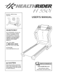
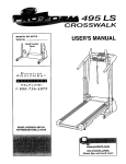
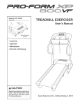
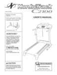
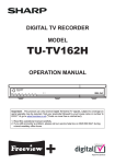
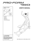
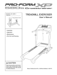
ModeJ No. 831.29675.1
SeriaJ No.
Serial Number Decal
\
TR
LL EXERCIS
User's Manual
\
• Assembly
• Operation
, Maintenance
, Part List and Drawing
Sears, Roebuck
and Co., Hoffman
Estates,
IL 60179
TABLE OF CONTENTS
iMPORTANT PRECAUTIONS
................................................................
BEFORE YOU BEGIN ......................................................................
ASSEMBLY ...............................................................................
OPERATION AND ADJUSTMENT .............................................................
HOW TO FOLD AND MOVE THE TREADMILL ..................................................
TROUBLESHOOTING
.....................................................................
CONDiTiONiNG GUiDELiNES ...............................................................
PART LiST ..............................................................................
ORDERING REPLACEMENT PARTS ..................................................
FULL 90 DAY WARRANTY
..........................................................
Note: An EXPLODED DRAWING is attached in the center of this manual.
IMPORTANT
PRECAUTIONS
2
4
5
8
21
22
24
26
Back Cover
Back Cover
BEFORE YOU BEGIN
Thank you for selecting the revolutionary PROFORM ®
XP 550S treadmill. The XP 550S treadmill offers an
impressive array of features designed to make your
workouts at home more enjoyable and effective. And
when you're not exercising, the unique XP 550S treadmill can be folded up, requiring less than half the floor
space of other treadmills.
ing this manual, call 1-800-4-MY-HOME ®(1-800-4694663).To help us assist you, please note the product
model number and serial number before calling. The
model number of the treadmill is 831.29675.1. The serial number can be found on a decal attached to the
treadmill (see the front cover of this manual for the location).
For your benefit, read this manual carefully before
using the treadmill. If you have questions after read-
Before reading further, please review the drawing
below and familiarize yourself with the labeled parts.
Fan
Accessory Tray
Console
Handrail
Pulse Sensor
Key/Clip
Storage Latch
Upright
Reset/Off
Breaker
Walking Belt
Foot Rail
Power Cord
\
Cushioned Walking Platform
for maximum exercise comfort
BACK
RIGHT SIDE
Rear Roller
Adjustment Bolts
4
ASSEMBLY
Make sure that the power cord is unplugged. Assembly requires two persons. Set the treadmill in a cleared
area and remove all packing materials. Do not dispose of the packing materials until assembly is completed. Note:
The underside of the treadmill walking belt is coated with high-performance lubricant. During shipping, a small
amount of lubricant may be transferred to the top of the walking belt or the shipping carton. This is a normal condition and does not affect treadmill performance. If there is lubricant on top of the walking belt, simply wipe off the
lubricant with a soft cloth and a mild, non-abrasive cleaner.
Assembly requires the included allen wrenches
_ and your own phillips
screwdriver
(_]_======_
and wire cutters _ _
Use the drawings below to identify the assembly hardware. The number in parentheses below each drawing is
the key number of the part, from the PART LIST on pages 26 and 27. The number after the parentheses shows
the quantity needed for assembly. Note: If a part is not in the parts bag, check to see if it is preattached to one of
the parts to be assembled, if a part is missing, call toll-free 1-888-533-1333. To avoid damaging plastic
parts, do not use power tools for assembly.
Screw (95)-8
Nut (20)-4
1" Screw (88)-4
3/4" Tek Screw (52)-4
Washer (71)-4
Base Pad Screw (40)-4
1 3/4" Bolt (76)-2
Wheel Bolt (90)-2
3" Bolt (86)-2
With the help of a second person, raise the Uprights (97)
to the vertical position.
Insert a Handrail Extension (105) into the post on the left
Upright (97), and align the small holes in the sides of the
Handrail Extension with the small holes in the sides of
the post. Make sure that the Handrail Extension is
oriented so the slot is on top. Tighten two 3/4" Tek
Screws (52) into the sides of the post; make sure that
the Screws are not directly opposite each other.
Next, identify a Left Bottom Handgdp (43), which has a
large hole for the latch assembly. Hold the Left Bottom
Handgdp against the Handrail Extension (105) and the
post, and tighten two 1" Screws (88) and one Screw (95)
down into the Left Bottom Handgdp as shown.
81
Hole
43
95
Attach the Left Top Handgdp (81) with three Screws (95)
inserted through the Left Bottom Handgdp (43).
Repeat this step on the right side of the treadmill.
97
Removetheknobfromthepin.Makesurethatthecollar
andthespringareon thepin.
InsertthepinintotheLeftBottomHandgrip(43),and
tightentheknobbackontothepin.
2
Knob
Placethetreadmillin thestorageposition(seeHOWTO
FOLDTHETREADMILL
FORSTORAGE
onpage21).
43
Spring
Collar
Pin
Havea secondpersontipthe Uprights(97)forwardand
holdthem.
OrienttheU-base(89)so theBasePads(99)areunderneathit,andpositiontheU-baseagainstthebaseof
theUprights(97)as shown.Inserttwo3" Bolts(86)into
theU-base(89)andthebaseoftheUprights(97);if
necessary,
tip theUprightsforwardas youinsertthe
Bolts.FingertightentwoNuts(20)withWashers(71)
ontothe Bolts.
Next,inserttwo1 3/4"Bolts(76)withWashers(71)into
thebaseofthe UprightsandtheU-base;if necessary,
tipthe Uprightsforwardas youinserttheBolts.Start
bothBoltsandthenfirmlytightenthem.
99
86
71
86
71 20
LowerthetreadmillFrame(59)(seeHOWTOLOWER
THETREADMILL
FORUSEonpage21).Withthehelp
ofa secondperson,carefullytiptheUprights(97)down
asshown.
FirmlytightenthetwoNuts(20)onthe3" Bolts(86).
97
AttachfourBasePads(99)tothebaseof theUprights
(97)withfourBasePadScrews(40)inthelocations
shown.
j99
40
99
/
4O
40
Attach the two Wheels (94) to the base of the Uprights
(97) with two Wheel Bolts (90), four Wheel Spacers (79),
and two Nuts (20) as shown. Do not overtighten the
Nuts; the Wheels must be able to turn freely.
97
With the help of a second person, carefully raise the
Uprights (97) to the vertical position.
94
7. Make sure that all parts are properly tightened before you use the treadmill. Note: Extra hardware may
be included. Keep the included allen wrenches in a secure place. The large allen wrench is used to adjust the
walking belt (see page 23). To protect the floor or carpet, place a mat under the treadmill.
If you purchase the optional chest pulse sensor (see
page 20), follow the steps below to install the receiver
included with the chest pulse sensor.
1. Make sure that the power cord is unplugged. Remove
the indicated Screw (95) and the Access Door (96) from
the left side of the Console Base (101).
2. Connect the wire on the receiver (A) to the indicated wire
extending from the Console Base (101). Hold the receiver so the small cylinder is oriented as shown and
is facing the Console Back. Attach the receiver to the
plastic posts on the Access Door (96) with the two included small screws.
3. Make sure that no wires are pinched. Reattach the
Access Door (96) with the Screw (95). Discard the other
wires included with the receiver.
101
Small
Screws
95
Cylinder
OPERATION AND ADJUSTMENT
THE PRE=LUBRICATED
WALKING BELT
an equipment-grounding conductor and a grounding
plug. Plug the power cord into a surge suppressor,
and plug the surge suppressor into an appropriate
outlet that is properly installed and grounded in
accordance with all local codes and ordinances.
Important: The treadmill is not compatible with
GFCl=equipped outlets.
Your treadmill features a walking belt coated with highperformance lubricant, iMPORTANT: Never apply silicone spray or other substances to the walking
belt or the walking platform. Such substances will
deteriorate the walking belt and cause excessive
wear.
This product is for use on a nominal 120-volt circuit,
and has a grounding plug that looks like the plug illustrated in drawing 1 below. A temporary adapter that
looks like the adapter illustrated in drawing 2 may be
used to connect the surge suppressor to a 2-pole
receptacle as shown in drawing 2 if a properly
grounded outlet is not available.
HOW TO PLUG IN THE POWER CORD
I
Your treadmill, like any other type of sophisticated
electronic equipment, can be seriously damaged by
sudden voltage changes in your home's power.
Voltage surges, spikes, and noise interference can
result from weather conditions or from other appliances
being turned on or off. To decrease the possibility of
your treadmill being damaged, always use a surge
suppressor with your treadmill (see drawing 1 at
the right). To purchase a surge suppressor, see
your local Sears store or call 1=800=366=7278 and
order part number 146148, or see your local elec=
tronics store.
Grounded Outlet Box
_.._
--
Surge Suppressor
_'<
"-. Grounding Pin
Grounding Pin
_rounded Outlet
Grounding Plug
2
_rounded Outlet Box
Adapter
Surge Suppressor
Use only a single-outlet surge suppressor that is
UL 1449 listed as a transient voltage surge sup=
pressor (TVSS). The surge suppressor must have a
UL suppressed voltage rating of 400 volts or less
and a minimum surge dissipation of 450 joules.
The surge suppressor must be electrically rated for
120 volts AC and 15 amps. There must be a moni=
toting light on the surge suppressor to indicate
whether it is functioning
properly. Failure to use a
properly functioning surge suppressor could result
in damage to the control system of the treadmill, if
the control system is damaged, the walking belt
may change speed, accelerate, or stop unexpect=
edly, which may result in a fall and serious injury.
The temporary adapter should be used only until a
properly grounded outlet (drawing 1) can be installed
by a qualified electrician.
This product must be grounded. If it should malfunction or break down, grounding provides a path of least
resistance for electric current to reduce the risk of electric shock. This product is equipped with a cord having
grounded
Metal Screw
_
"
The green-colored rigid ear, lug, or the like extending
from the adapter must be connected to a permanent
ground such as a properly grounded outlet box cover.
Whenever the adapter is used it must be held in place
by a metal screw. Some 2=pole receptacle outlet box
covers are not grounded. Contact a qualified elec=
trician to determine if the outlet box cover is
8
before using an adapter.
CONSOLEDIAGRAM
i FiT
PROGRAM
SELECT
START
FEATURES OF THE CONSOLE
The treadmill console offers an impressive array of
features designed to make your workouts more effective.
When the manual mode of the console is selected, the
speed and incline of the treadmill can be changed with
the touch of a button. As you exercise, the console will
display continuous exercise feedback. You can even
measure your heart rate using the built-in handgrip
pulse sensor or the optional chest pulse sensor (see
page 20).
In addition, the console features four preset programs.
Each program automatically controls the speed and incline of the treadmill to give you an effective workout.
You can even create your own custom programs and
store them in memory for future reference.
The console also features iFIT.com interactive technology. Having iFIT.com technology is like having a personal trainer in your home. Using a stereo audio cable,
you can connect the treadmill to your portable stereo,
home stereo, computer, or VCR and play special
iFIT.com MP3, CD, and video programs (iFIT.com MP3
programs, CDs, and vide.cassettes are available separately), iFIT.com programs automatically control the
speed and incline of the treadmill as a personal trainer
guides you through every step of your workout; highenergy music provides added motivation. To down=
load iRT.com IVIP3 programs, go to www.iFIT.com.
To purchase iFIT.com CDs or vide,cassettes, call
toll-free 1=888=533=1333.
With the treadmill connected to your computer, you
can also go to www.iFIT.com and access iFIT.com
programs directly from our Web site. See
www.iFIT.com for more information.
To use the manual mode of the console, follow the
steps beginning on page 10. To use a preset
program, see page 12. To create and use a custom
program, see pages 13 and 14. To use an iRT.com
IVIP3, CD, or video program, see page 17. To use an
iFIT.com program directly from our Web site, see
page 19.
HOWTOTURNONTHEPOWER
crease and decrease
buttons. Each time a
button is pressed, the
speed setting will
change by 0.1 mph; if a
button is held down, the
speed setting will change in increments of 0.5
mph. Note: After the buttons are pressed, it may
take a moment for the walking belt to reach the selected speed setting.
Pluginthepowercord(seepage8).
Locatethereset/off
circuitbreakernear
thepowercord.Make
surethatthecircuit
breakeris inthereset
position.
Position
Reset
Standonthefootrailsofthetreadmill.Findtheclip
attached
tothekey(seethedrawingonpage9),
andslidetheclipontothewaistband
ofyour
clothes.Next,insertthekeyintotheconsole.The
displaywilllight.Important:In anemergency
situation,the keycan be pulled from the console, causing the walking belt to slow to a
stop. Test the clip by carefully taking a few
steps backward; if the key is not pulled from
the console, adjust the position of the clip.
If one of the numbered speed buttons is pressed,
the walking belt will gradually increase in speed
until it reaches the selected speed setting.
To stop the walking belt, press the Stop button. To
restart the walking belt, press the Start button, the
Speed increase button, or one of the numbered
buttons.
Note: The first time the treadmill is used, observe
the alignment of the walking belt, and center the
walking belt if necessary (see page 23).
Change the incline of the treadmill
as desired.
HOW TO USE THE MANUAL MODE
To change the incline of
the treadmill, press the
Incline increase and decrease buttons. Each
time a button is pressed,
the incline will change by
0.5%. Note: After the buttons are pressed, it may
take a moment for the treadmill to reach the selected incline setting.
Insert the key into the console.
See HOW TO TURN ON THE POWER above.
Select the manual mode.
When the
U'&,J U
UU
key is inmmmmm
m
m
m
m
serted, the
B
m
manual
mmJl_mm
mode will
Track
be selected.
If a program
has been selected, reselect the manual mode by
pressing the Program Select button repeatedly
until a track appears in the lower part of the display and the letters '1FIT" do not appear.
Start the walking
Follow your progress with the display.
Note: The display can be backlit with any of
five colors. To select the desired color, press
the Display Color button repeatedly.
When the
manual mode
mlmmm
!
m
E
m
or the
m
iFIT.com
mode is seTrack
lected, the
lower part of
the display will show a 1/4-mile track. As you walk
or run, the indicators around the track will appear
in succession until the entire track appears. The
track will then disappear and the indicators will
again begin to appear in succession.
belt.
To start the walking belt, press the Start button,
the Speed increase button, or one of the speed
buttons numbered 1 through 10.
if the Start button or the Speed increase button is
pressed, the walking belt will begin to move at 1
mph. As you exercise, change the speed of the
walking belt as desired by pressing the Speed in-
10
The left side of the dis-
move the
sheets of clear
plastic from the
metal contacts.
In addition,
make sure that
play will show the incline
level of the treadmill, the
elapsed time, the approximate number of
grams of carbs you have
burned, and the distance you have walked or run.
Note: Each time the incline changes, the display
will show the incline setting for a few seconds
When a program is selected, the display will show
the time remaining in the program instead of the
elapsed time.
Contacts
your hands are
clean.
To measure your heart rate, stand on the foot
rails and hold the metal contacts on the handgrip
pulse sensor--avoid
moving your hands. When
your pulse is detected, the heart symbol in the
right side of the display will begin to flash, one or
two dashes will appear, and then your heart rate
will be shown. For the most accurate heart rate
The right side of the
display will show the
speed of the walking
belt, the approximate
number of calories you
have burned, and your
pace (in minutes per mile). The right side of the
display will also show your heart rate when you
use the handgrip pulse sensor or the optional
chest pulse sensor.
reading, continue to hold the contacts
about 15 seconds.
for
Turn on the fan if desired.
To turn on the fan, press the fan button (located
next to the Display Color button). To turn on the
fan at medium speed, press the button a second
time. To turn on the fan at high speed, press the
button a third time. To turn off the fan, press the
button a fourth time. Note: If the fan is left on
when the walking belt is stopped, the fan will automatically turn off after a few minutes.
Note: The console can
display speed and distance in either miles or
kilometers. To determine
which unit of measurement is selected, hold
down the Stop button while inserting the key into
the console. An "E" for English miles or an "M" for
metric kilometers will appear in the right side of the
display. Press the Speed increase button to
change the unit of measurement. When the desired unit of measurement is selected, remove the
key. Note: For simplicity, all instructions in this
section refer to miles.
When you are finished
key from the console.
exercising,
remove the
Step onto the foot rails, press the Stop button, and
adjust the incline of the treadmill to the lowest
setting. The incline must be at the lowest setting
when the treadmill is folded to the storage position or the treadmill will be damaged. Next, remove the key from the console and put it in a secure place. Note: if the display remains lit after
the key is removed, the console is in the
"demo" mode. See page 20 and turn off the
demo mode.
To reset the display, press the Stop button, remove the key, and then reinsert the key.
Measure your heart rate if desired.
Note: If you use the handgdp pulse sensor and
the optional chest pulse sensor at the same time,
the console will not display your heart rate accurately. Before using the handgdp pulse sensor, re-
When you are finished using the treadmill,
switch the reset/off circuit breaker to the "off"
position and unplug the power cord.
11
tings for the next four segments will be shown in
the four columns to the right.
HOW TO USE A PRESET PROGRAM
insert the key fully into the console.
When only three seconds remain in the first segment of the program, both the Current Segment
column and the column to the right will flash and a
series of tones will sound. If the speed and/or incline of the treadmill is about to change, the speed
setting and/or the incline setting will flash in the
display to alert you.
See HOW TO TURN ON THE POWER on page
10.
Select one of the four preset programs.
To select one of the four preset programs, press
the Program Select button repeatedly until "P3,"
"P4," "P5," or "P6" appears in the display. A few
seconds after a preset program is selected, the
maximum
speed setting of the
_
Us PEED
program and
the maximum incline
M
setting of the
Jm
mmll
mEmfmmm
program will
flash in the
display for a
few seconds; in addition, the display will show
how long the program will last. The matrix in the
lower part of the display will show the first seven
speed settings of the program.
When the first segment is completed, a//speed
seUif/g¢ wi// move one co/utah to the/eft.. The
speed setting for the second segment will then be
shown in the flashing Current Segment column
and the treadmill will automatically adjust to the
speed and incline settings for the second segment. Note: If all five of the indicators in the
Current Segment column are lit, /he s/2eed._eUing_
maymove downward/so that only the highest indicators appear in the matrix.
The program will continue in this way until the
speed setting for the last segment is shown in the
Current Segment column and the last segment
ends. The walking belt will then slow to a stop.
If the speed or incline setting for the current
segment is too high or too low, you can manually
override the setting by pressing the Speed or
Incline buttons. Every few times a Speed button is
pressed, an additional indicator will appear or disappear in the Current Segment column; if any of
the columns to the right of the Current Segment
column have the same number of lit indicators as
Press the Start button or the Speed increase
button to start the program.
A moment after the button is pressed, the treadmill will automatically adjust to the first speed and
incline settings for the program. Hold the handrails
and begin walking.
the Current Segment column, an additional indicator may appear or disappear in those columns as
well. Important: When the current segment of
the program ends, the treadmill will automatically adjust to the speed and incline settings
for the next segment.
Each program is divided into either 30 or 50 oneminute segments. One speed setting and one incline setting are programmed for each segment.
Note: The same speed setting and/or incline setting may be programmed for two or more consecutive segments.
The speed
setting for
the first segment will be
shown in the
To stop the program at any time, press the Stop
button. To restart the program, press the Start button or the Speed increase button. The walking belt
will begin to move at 1 mph. When the next segment of the program begins, the treadmill will automatically adjust to the speed and incline settings
for the next segment.
m
Em
mmm
mmmE
Current Segment
flashing
Current
Segment column of the matrix. (The incline settings are not shown in the matrix.) The speed set-
12
Press the Start button or the Speed increase
button and program the desired speed and incline settings.
Follow your progress with the display.
See step 5 on page 10.
A moment after the button is pressed, the walking
belt will begin to move. Hold the handrails and
begin walking.
Measure your heart rate if desired.
See step 6 on page 1 1.
Refer to the matrix. Each custom program is divided into one-minute segments. One speed setting and one incline setting can be programmed
for each segment. The speed setting for the first
segment is
shown in
Turn on the fan if desired.
See step 7 on page 11.
When you are finished
key from the console.
exercising,
remove the
the flashing
Current
See step 8 on page 11.
Segment
column of
the matrix.
Insert the key into the console.
See HOW TO TURN ON THE POWER on page
10.
To select a
p
_
CUSTOMI
When the first segment of the program ends, a series of tones will sound and the current speed setting and the current incline setting will be saved in
memory. The three columns of indicators HI///then
move one co/umn to the/eft, and the speed setting for the second segment will be shown in the
flashing Current Segment column. Program a
speed setting and an incline setting for the second
segment as described above.
Select one of the custom programs.
ton repeatedly until
"Pl" or
PROGRAM
(The incline
settings are not shown in the matrix.) To program
a speed setting and an incline setting for the first
segment, simply adjust the speed and incline of
the treadmill as desired by pressing the Speed
and Incline buttons. Every few times a Speed button is pressed, an additional indicator will appear
or disappear in the Current Segment column.
HOW TO CREATE CUSTOM PROGRAMS
custom
program,
press the
Program
Select but-
_
Current Segment
Continue programming speed and incline settings
for as many segments as desired; custom programs can have up to forty segments. When you
are finished with your workout, press the Stop button twice. The speed and incline settings that you
have programmed and the number of segments
that you have programmed will then be saved in
memory.
CUSTOM
PROGRAM
"P2" appears in the display.
Note: If the custom program has not yet been
defined, only three columns of indicators will
appear in the matrix in the lower part of the
display. If more than three columns of indicators appear, see HOW TO USE CUSTOM PRO=
GRAMS on page 14.
When you are finished
key from the console.
See step 8 on page 11.
13
exercising,
remove the
speed settings for the next four segments are
shown in the columns to the right.
HOW TO USE CUSTOM PROGRAMS
insert the key into the console.
When only three seconds remain in the first segment of the program, both the Current Segment
column and the column to the right will flash, a
series of tones will sound, and the speed setting
and the incline setting will flash in the display.
When the first segment ends, a//,_peed,_ettifTgS
wi// move one co/umf7 to the/eft. The speed setting
for the second segment will then be shown in the
flashing Current Segment column, and the treadmill will automatically adjust to the second speed
and incline settings that you programmed previously.
See HOW TO TURN ON THE POWER on page
10.
Select one of the custom
programs.
To select a custom program, press the Program
Select button repeatedly until "PI" or "P2" appears
in the display. A few seconds after a custom program is selected, the maximum speed setting of
the program
and the
maximum
N Ji_
_
°
_NCL,NE
U,U
_.UItls_EE
incline setting of the
program will
flash in the
T_M_
qL.3f'PJ U
__
The program will continue in this way until the
speed setting for the last segment is shown in the
Current Segment column and the last segment
ends. The walking belt will then slow to a stop.
U,U
CUSTOM
If desired, you can redefine to the program while
using it. To change the speed or incline setting
for the current segment, simply press the Speed
or Incline buttons. When the current segment ends,
the new setting will be saved in memory. To in=
crease the length of the program, first wait until
the program is completed. Then, press the Start button and program speed and incline settings for as
many additional segments as desired. When you
have added as many segments as desired, press
the Stop button twice. To decrease the length of
the program, press the Stop button twice at any
time before the program is completed.
___
PROGRAM
display for a
few seconds; in addition, the display will show how long the program
will last. The matrix in the lower part of the display
will show the first seven speed settings of the program.
Note: if only three columns of indicators appear in the matrix, see HOW TO CREATE A
CUSTOM PROGRAM on page 13.
Press the Start button or the Speed increase
button to start the program.
To stop the program temporarily, press the Stop
button. To restart the program, press the Start button or the Speed increase button.
A moment after the button is pressed, the treadmill will automatically adjust to the first speed and
incline settings that you programmed previously.
Hold the handrails and begin walking.
Follow your progress with the display.
See step 5 on page 10.
Each custom program is divided into several oneminute segments. One speed setting and one incline setting are programmed for each segment.
(The same speed setting and/or incline setting
may be profor two o r
more congrammed
secutive
Measure your heart rate if desired.
See step 6 on page 11.
Turn on the fan if desired.
_ilmlllllllll
mm,,,_mmm
CUSTOM
See step 7 on page 11.
segments.)
I
Current Segment
The speed
setting for
the first segment will be shown in the flashing
Current Segment column of the matrix. (The incline settings are not shown in the matrix.) The
When you are finished
key from the console.
See step 8 on page 11.
14
exercising,
remove the
HOW TO CONNECT YOUR PORTABLE
STEREO
Note: if your stereo has an RCA-type AUDIO OUT
jack, see instruction A below, if your stereo has a
1/8" LINE OUT jack, see instruction B. If your
stereo has only a PHONES jack, see instruction C.
To use iFIT.com MP3 or CD programs, the treadmill
must be connected to your MP3 player, CD player,
portable stereo, home stereo, or computer. See pages
t 5 and 16 for connecting instructions. To use JFIT.com
programs directly from our Web site, the treadmill
must be connected to your computer. See page t 6 for
connecting instructions. To use iFIT.com video pro=
grams, the treadmill must be connected to your VCR.
See page t 7 for connecting instructions.
A. Plug one end of a long 1/8" to RCA stereo audio
cable (available at electronics stores) into the input
jack on the console. Plug the other end of the cable
into the AUDIO OUT jack on your stereo.
A/B
HOW TO CONNECT YOUR MP3 PLAYER OR CD
PLAYER
A. Plug one end of the included 1/8" to 1/8" stereo
audio cable into the input jack on the console. Plug
the other end of the cable into a jack on your MP3
player or CD player. Plug your headphones into the
headphone jack on the console.
,m_
®, i _,_
iy
.......
Audio Cable
B,
See the drawing above. Plug one end of a long 1/8"
to 1/8" stereo audio cable (available at electronics
stores) into the input jack on the console. Plug the
other end of the cable into the LINE OUT jack on
your stereo. Note: While the cable is plugged into
the LINE OUT jack, do not plug your headphones
into the headphone jack on the console.
C,
Plug one end of a long 1/8" to 1/8" stereo audio
cable (available at electronics stores) into the input
jack on the console. Plug the other end of the cable
into the PHONES jack on your stereo. Plug your
headphones into the headphone jack on the console.
......................................
:
: :
:
i
i
.....................
._ /_:::::::::::_;
__
9=====_
Audio
Cable
.... Headphones
C
r
i
,@ © @,
Lq--d.-
L........
.... Headphones
15
HOW TO CONNECT YOUR HOME STEREO
HOW TO CONNECT YOUR COMPUTER
Note: if your stereo has an unused LiNE OUT jack,
see instruction A below. If the LiNE OUT jack is
being used, see instruction B.
A. Plug one end of a long 1/8" to 1/8" stereo audio
cable (available at electronics stores) into the input
jack on the console. Plug the other end of the cable
into the MNE OUT jack on your computer. Note:
While the cable is plugged into the LINE OUT jack,
do not plug your headphones into the headphone
jack on the console.
A. Plug one end of a long 1/8" to RCA stereo audio
cable (available at electronics stores) into the input
jack on the console. Plug the other end of the cable
into the MNE OUT jack on your stereo. Note: While
the cable is plugged into the LINE OUT jack, do not
plug your headphones into the headphone jack on
the console.
A
.......
2
........
A
r ......
i
[email protected]
i ....
B. Plug one end of a long 1/8" to RCA stereo audio
cable (available at electronics stores) into the input
jack on the console. Plug the other end of the cable
into an RCA Y-adapter (available at electronics
stores). Next, remove the wire that is currently
plugged into the LINE OUT jack on your stereo and
plug the wire into the unused side of the Y-adapter.
Plug the Y-adapter into the LINE OUT jack on your
stereo. Note: While the Y-adapter is plugged into the
LINE OUT jack, do not plug your headphones into
the headphone jack on the console.
,@ © @,
i
L ....
J.-
Audio
Cable
=
Audio Cable
LINE
OUT
..............
......
RCA
Y-adapter
Wire removed from-_'_.-_
LiNE OUT jack
16
ooc
HOW TO CONNECT YOUR VCR
HOW TO USE AN IFIT.COM MP3, CD, OR VIDEO
PROGRAM
Note: if your VCR has an unused AUDIO OUT jack,
see instruction A below, if the AUDIO OUT jack is
being used, see instruction B. If you have a TV
with a built=in VCR, see instruction B. if your VCR
is connected to your home stereo, see HOW TO
CONNECT YOUR HOME STEREO on page 16.
To use an iFIT.com MP3, CD, or video program, the
treadmill must be connected to your MP3 player, CD
player, or VCR. See HOW TO CONNECT THE
TREADMILL TO USE IFIT.COM PROGRAMS on
pages 15 to 17. To download iFIT.com MP3 programs, go to wwwJFIT.com. To purchase iFIT.com
CDs or videocassettes,
call toll=free 1=888=533=1333.
A. Plug one end of a long 1/8" to RCA stereo audio
cable (available at electronics stores) into the input
jack on the console. Plug the other end of the cable
into the AUDIO OUT jack on your VCR.
Follow the steps below to use an iFIT.com MP3, CD,
or video program.
A
r
u
L£t2J
insert the key into the console.
See HOW TO TURN ON THE POWER on page 10.
Select the iFIT.com mode.
To select the
iFIT.com
mode, press
the iFIT button. The letters "iFIT" will
Audio Cable
B. Plug one end of a long 1/8" to RCA stereo audio
cable (available at electronics stores) into the input
jack on the console. Plug the other end of the cable
into an RCA Y-adapter (available at electronics
stores). Next, remove the wire that is currently
plugged into the AUDIO OUT jack on your VCR and
plug the wire into the unused side of the Y-adapter.
Plug the Y-adapter into the AUDIO OUT jack on
your VCR.
===mm==_=v_=a=n==m
i FIT
__
appear in the display.
Press the Play button on your MP3 player, CD
player, or VCR.
Note: If you are using an iFIT.com CD, insert the
CD into your CD player; if you are using an
iFIT.com videocassette, insert the videocassette
into your VCR.
A moment after the Play button is pressed, your
personal trainer will begin guiding you through
your workout. Simply follow your personal trainer's
instructions. Note: If the time is flashing in the display, press the Start button or the Speed increase
button on the console. The treadmill will not respond to an MP3, CD, or video program while the
time is flashing in the display.
During the program, an electronic "chirping" sound
will alert you when the speed and/or incline of the
treadmill is about to change. CAUTION: Always
listen for the "chirp" and be prepared for speed
and/or incline changes, in some instances, the
speed and/or incline may change before your
personal trainer describes the change.
AUDIO OUT jack
17
If the speed or incline settings are too high or too
low, you can manually override the settings at any
time by pressing the Speed or Incline buttons on
the console. However, when the next "chirp" is
heard, the speed and/or incline will change to
the next settings of the program.
, Make sure that the audio cable is properly
connected.
To stop the walking belt at any time, press the
Stop button on the console. To restart the program, press the Start button or the Speed increase button. After a moment, the walking belt
will begin to move at 1.0 mph. When the next
"chirp" is heard, the speed and/or incline will
change to the next settings of the program.
, See THE iNCLiNE OF THE TREADMILL DOES
NOT CHANGE CORRECTLY on page 22.
, if you are using a portable CD player and the
CD skips, set the CD player on the floor or an=
other flat surface instead of on the console.
Follow your progress with the display.
See step 5 on page 10.
Measure your heart rate if desired.
When the program is completed, the walking belt
will stop. Note: To use another MP3, CD, or video
program, press the Stop button or remove the key
and go to step 1 on page 17.
See step 6 on page 11.
Turn on the fan if desired.
Note: if the speed and/or incline of the treadmill
does not change when a "chirp" is heard:
See step 7 on page 11.
When you are finished
key from the console.
, Make sure that the letters "iFIT" appear in the
display and that the time is not flashing in the
display, if the time is flashing, press the Start
button or the Speed increase button on the
console.
exercising, remove the
See step 8 on page t t.
CAUTION: Always remove iFIT.com CDs and
videocassettes from your CD player and VCR
and disconnect your MP3 player when you are
not using them.
, Adjust the volume of your MP3 player, CD
player, or VCR. if the volume is too high or too
low, the console may not detect the program
signals.
18
_
When the on-screen countdown ends, the program
will begin and the walking belt will begin to move.
Hold the handrails, step onto the walking belt, and
begin walking. During the program, an electronic
"chirping" sound will alert you when the speed
and/or incline of the treadmill is about to change.
CAUTION: Always listen for the "chirp" and be
prepared for speed and/or incline changes.
Our Web site at www.iFIT.com allows you to access
basic programs, audio programs, and video programs
directly from the intemet. Additional options are soon to
be available. See www.iFIT.com for details.
To use programs from our Web site, the treadmill must
be connected to your home computer. See HOW TO
CONNECT YOUR COMPUTER on page 16. In
addition, you must have an internet connection and
an internet service provider. A list of specific system requirements is found on our Web site.
If the speed or incline settings are too high or too
low, you can manually override the settings at any
time by pressing the Speed or Incline buttons on
the console. However, when the next "chirp" is
heard, the speed and/or incline will change to
the next settings for the program.
Follow the steps below to use a program from our
Web site.
Insert the key into the console.
To stop the walking belt at any time, press the
Stop button on the console. To restart the program, press the Start button or the Speed increase button. After a moment, the walking belt
will begin to move at 1.0 mph. When the next
"chirp" is heard, the speed and incline will
change to the next settings of the program.
See HOW TO TURN ON THE POWER on page 10.
Select the iFIT.com mode.
To select
the iFIT.com
mode, press
the iFIT button. The letters "iFIT"
mlllllmmll_lllllll_
i FIT
eturn to the treadmill and stand on the foot
rails. Find the clip attached to the key and slide
the clip onto the waistband of your clothes.
When the program is completed, the walking belt
will stop. Note: To use another program, press the
Stop button and go to step 5.
_mlmm_
will appear in the display.
Note: If the speed and/or incline of the treadmill
does not change when a "chirp" is heard, make
sure that the letters "iFIT" appear in the display
and that the time is not flashing in the display.
In addition, make sure that the audio cable is
properly connected.
Go to your computer and start an internet
connection.
Start your web browser, if necessary,
our Web site at www.iFIT.com.
and go to
Follow your progress with the display.
Follow the desired links on our Web site to select a program.
See step 5 on page 10.
Read and follow the on-line instructions for using a
program.
When you are finished
key from the console.
Follow the on-line instructions
to start the
See step 8 on page 11.
program.
When you start the program, an on-screen countdown will begin.
19
exercising,
remove the
THE INFORMATION
MODE/DEMO MODE
played in a store. When the console is in the demo
mode, the power cord can be plugged in, the key can
be removed from the console, and the indicators in the
display will automatically appear in a preset sequence,
although the buttons on the console will not operate. If a
"d" appears when the information mode is selected,
press the Speed decrease button so "d" disappears.
The console features an information mode that keeps
track of the total number of hours that the treadmill has
been operated and the total number of miles that the
walking belt has moved. The information mode also allows you to select miles or kilometers as the unit of
measurement and to turn on and turn off the demo
mode.
To exit the information mode, remove the key from the
console.
To select the information mode, hold down the Stop
button while inserting the key into the console. When
the information mode is selected, the following information will be shown in the display:
The left side of the display
will show the total number of
miles (or kilometers) that the
walking belt has moved and
the total number of hours
that the treadmill has been
THE OPTIONAL
An optional chest pulse sensor offers hands-free operation as it monitors your heart rate during your workouts. To purchase the optional chest pulse sensor,
call toll-free 1-888-533-1333.
E
Mile/
CHEST PULSE SENSOR
f_--Hours
used. An "E" for English miles or an "M" for metric kilometers will appear in the right side of the display. Press
the Speed increase button to change the unit of measurement.
IMPORTANT: If a "d" appears in the right side of the
display, the console is in the "demo" mode. This mode
is intended to be used only when a treadmill is dis-
2O
HOW TO FOLD AND MOVE THE TREADMILL
NOW TO FOLD THE TREADMILL
FOR STORAGE
Before folding the treadmill, adjust the incline to the
lowest position. If this is not done, the treadmill may be perma=
nently damaged. Remove the key and unplug the power cord.
CAUTION: You must be able to safely lift 45 pounds (20 kg) to
raise, lower, or move the treadmill.
1. Hold the treadmill with your hands in the location shown by the
arrow at the right. CAUTION: To decrease the possibility of
injury, bend your legs and keep your back straight. As
you raise the treadmill, make sure to lift with your legs
rather than your back. Raise the treadmill about halfway to
the vertical position.
2. Move your right hand to the position shown, and hold the
treadmill firmly. Using your left hand, pull the latch knob to
the left and hold it. Raise the treadmill until the catch is past
the latch pin. Slowly release the latch knob. Make sure that
the frame is securely held by the latch pin.
To protect the floor or carpet from damage, place a mat
under the treadmill. Keep the treadmill out of direct sun=
light. Do not leave the treadmill in the storage position in
temperatures above 85 ° Fahrenheit.
Latch
HOW TO MOVE THE TREADMILL
Before moving the treadmill, convert the treadmill to the storage
position as described above. Make sure that the frame is held
securely by the latch pin.
Frame
1. Hold the frame and place one foot against a wheel.
2. Tilt the treadmill back until it rolls freely on the wheels.
Carefully move the treadmill to the desired location. Never
move the treadmill without tipping it back. To reduce the
risk of injury, use extreme caution while moving the
treadmill. Do not attempt to move the treadmill over an
uneven surface.
3. Place one foot on wheel, and carefully lower the treadmill
until it is resting in the storage position.
HOW TO LOWER THE TREADMILL
Wheels
FOR USE
1. See drawing 2 above. Hold the upper end of the treadmill with your right hand. Pull the latch knob to the left
and hold it. Pivot the treadmill down until the frame is past the latch pin.
2. See drawing 1 above. Hold the treadmill firmly with both hands, and lower the treadmill to the floor.
CAUTION: To decrease the possibility of injury, bend your legs and keep your back straight.
21
TROUBLESHOOTING
Most treadmill problems can be solved by following the simple steps below. Find the symptom that
applies, and follow the steps listed, if further assistance is needed, call toll=free 1-800-4-MY-HOME ®
(1-800-469-4663).
PROBLEM:
The power does not turn on
SOLUTION:
a. Make sure that the power cord is plugged into a surge suppressor, and that the surge suppressor
is plugged into a properly grounded outlet (see page 8). Use only a single-outlet surge suppressor
that meets all of the specifications described on page 8. Important: The treadmill is not compatible
with GFCl-equipped outlets.
b. After the power cord has been plugged in, make sure that the key is fully inserted into the console.
C.
Check the reset/off circuit breaker located on the
treadmill frame near the power cord. If the switch
protrudes as shown, the circuit breaker has
tripped. To reset the circuit breaker, wait for five
minutes and then press the switch back in.
Reset
Tripped
PROBLEM:
The power turns off during
use
SOLUTION:
a. Check the reset/off circuit breaker (see the drawing above). If the circuit breaker has tripped, wait
for five minutes and then press the switch back in.
b. Make sure that the power cord is plugged in. If the power cord is plugged in, unplug it, wait for
five minutes, and then plug it back in.
c. Remove the key from the console. Reinsert the key fully into the console.
d. If the treadmill still will not run, please call toll-free 1-800-4-MY-HOME _ (1-800-469-4663).
PROBLEM:
The incline of the treadmill
does not change correctly
SOLUTION:
a. With the key in the console, press one of the Incline buttons. While the incline is changing, remove the key. After a few seconds, re-insert the key. The treadmill will automatically rise to the
maximum incline level and then return to the minimum level. This will recalibrate the incline system.
PROBLEM:
The displays
SOLUTION:
a. Remove the key from the console and UNPLUG THE
POWER CORD. With the help of a second person,
carefully tip the Uprights (97) down as shown. Remove
the three Hood Screws (44) and the two Screws (95).
Note: A phillips screwdriver with a shaft at least 5" long
is required.
of the console do not function
properly
44
7
]95
95
22
With the help of a second person, carefully raise the
Uprights (97) as shown. Carefully pivot the Hood (93)
off.
93
Locate the Reed Switch (22) and the Magnet (19) on
the left side of the Pulley (18). Turn the Pulley until the
Magnet is aligned with the Reed Switch. Make sure
that the gap between the Magnet and the Reed
Switch is about 1/8". If necessary, loosen the Screw
(23), move the Reed Switch slightly, and then
retighten the Screw. Reattach the Hood, and run the
treadmill for a few minutes to check for a correct
speed reading.
PROBLEM:
SOLUTION:
The walking
belt slows when walked on
a. Use only a single-outlet surge suppressor that meets all of the specifications described on page 8.
b,
If the walking belt is overtightened, treadmill performance may decrease and the walking belt may become damaged. Remove the key and UNPLUG THE
POWER CORD. Using the allen wrench, turn both
rear roller adjustment bolts counterclockwise, 1/4 of a
turn. When the walking belt is properly tightened, you
should be able to lift each side of the walking belt 2 to
3 inches off the walking platform. Be careful to keep
the walking belt centered. Plug in the power cord, insert the key, and run the treadmill for a few minutes.
Repeat until the walking belt is properly tightened.
Rear Roller Adjustment Bolts
c. If the walking belt still slows when walked on, please call toll-free 1-800-4-MY-HOME _ (1-800469-4663).
PROBLEM:
The walking
SOLUTION:
a. If the walking belt is off-center, first remove the key
and UNPLUG THE POWER CORD. If the walking
belt has shifted to the left, use the allen wrench to
turn the left rear roller bolt clockwise 1/2 of a turn; if
the walking belt has shifted to the right, turn the
bolt counterclockwise 1/2 of a turn. Be careful not to
overtighten the walking belt. Plug in the power cord,
insert the key, and run the treadmill for a few minutes.
Repeat until the walking belt is centered.
b,
belt is off-center
or slips when walked on
if the walking belt slips when walked on, first remove the key and UNPLUG THE POWER CORD.
Using the allen wrench, turn both rear roller bolts
clockwise, 1/4 of a turn. When the walking belt is correctly tightened, you should be able to lift each side of
the walking belt 2 to 3 inches off the walking platform.
Be careful to keep the walking belt centered. Plug in
the power cord, insert the key, and carefully walk on
the treadmill for a few minutes. Repeat until the walking belt is properly tightened.
23
CONDiTiONiNG
GUiDELiNES
is to burn fat, adjust the speed and incline of the treadmill until your heart rate is near the lowest number in
your training zone.
For maximum fat burning, adjust the speed and incline
of the treadmill until your heart rate is near the middle
number in your training zone.
Aerobic Exercise
If your goal is to strengthen your cardiovascular system, your exercise must be "aerobic." Aerobic exercise
is activity that requires large amounts of oxygen for
prolonged periods of time. This increases the demand
on the heart to pump blood to the muscles, and on the
lungs to oxygenate the blood. For aerobic exercise,
adjust the speed and incline of the treadmill until your
heart rate is near the highest number in your training
zone.
The following guidelines will help you to plan your exercise program. For more detailed exercise information, obtain a reputable book or consult your physician.
EXERCISE iNTENSiTY
WORKOUT
Whether your goal is to burn fat or to strengthen your
cardiovascular system, the key to achieving the
desired results is to exercise with the proper intensity.
The proper intensity level can be found by using your
heart rate as a guide. The chart below shows recommended heart rates for fat burning and aerobic exercise.
HEART
RATE
TRAINING
165
155
145
140
130
125
115
MAX
145
138
130
125
118
110
103
125
120
115
110
105
95
90
20
30
40
50
60
70
80
FAT BURN
FAT BURN
Age
Each workout should include the following three parts:
A Warm=up--Start each workout with 5 to 10 minutes
of stretching and light exercise. A proper warm-up increases your body temperature, heart rate and circulation in preparation for exercise.
Training Zone Exercise--After
warming up, increase
the intensity of your exercise until your pulse is in your
training zone for 20 to 60 minutes. (During the first few
weeks of your exercise program, do not keep your
pulse in your training zone for longer than 20 minutes.)
Breathe regularly and deeply as you exercise--never
hold your breath.
ZONES
AEROBIC
GUIDELINES
To find the proper heart rate for you, first find your age
near the bottom of the chart (ages are rounded off to
the nearest ten years). Next, find the three numbers
above your age. The three numbers define your "training zone." The lower two numbers are recommended
heart rates for fat burning; the higher number is the
recommended heart rate for aerobic exercise.
A Cool=down--Finish
each workout with 5 to 10 min-
utes of stretching to cool down. This will increase the
flexibility of your muscles and will help prevent postexercise problems.
EXERCISE FREQUENCY
Fat Burning
To maintain or improve your condition, complete three
workouts each week, with at least one day of rest between workouts. After a few months, you may complete up to five workouts each week if desired. The key
to success is to make exercise a regular and enjoyable
part of your everyday life.
To burn fat effectively, you must exercise at a relatively
low intensity level for a sustained period of time.
During the first few minutes of exercise, your body
uses easily accessible carbohydrate caloriesfor energy. Only after the first few minutes does your body
begin to use stored fatca/oriesfor
energy, if your goal
24
SUGGESTED STRETCHES
The correct form for several basic stretches is shown at the right. Move slowly as you stretch--never
1. Toe Touch Stretch
Stand with your knees bent slightly and slowly bend forward from
your hips. Allow your back and shoulders to relax as you reach
down toward your toes as far as possible. Hold for 15 counts, then
relax. Repeat 3 times. Stretches: Hamstrings, back of knees and
back.
2. Hamstring
Stretch
Sit with one leg extended. Bring the sole of the opposite foot toward
you and rest it against the inner thigh of your extended leg. Reach
toward your toes as far as possible. Hold for 15 counts, then relax.
Repeat 3 times for each leg. Stretches: Hamstrings, lower back and
groin.
3. Calf/Achilles
Stretch
With one leg in front of the other, reach forward and place your
hands against a wall. Keep your back leg straight and your back
foot flat on the floor. Bend your front leg, lean forward and move
your hips toward the wall. Hold for 15 counts, then relax. Repeat 3
times for each leg. To cause further stretching of the achilles tendons, bend your back leg as well. Stretches: Calves, achilles tendons and ankles.
4. Quadriceps
Stretch
With one hand against a wall for balance, reach back and grasp
one foot with your other hand. Bring your heel as close to your buttocks as possible. Hold for 15 counts, then relax. Repeat 3 times for
each leg. Stretches: Quadriceps and hip muscles.
5. Inner Thigh Stretch
Sit with the soles of your feet together and your knees outward. Pull
your feet toward your groin area as far as possible. Hold for 15
counts, then relax. Repeat 3 times. Stretches: Quadriceps and hip
muscles.
25
bounce.
PART LiST--Model
No. 831.29675.1
RO406A
To locate the parts listed below, see the EXPLODED DRAWING attached in the center of this manual.
Key No. Qty.
Description
Key No. Qty.
Description
1
2
1
8
Left Foot Rail
Foot Rail Screw
51
52
2
10
Static Decal
3/4" Tek Screw
3
4
5
6
1
2
1
2
Console
Isolator Decal
Catch
Front Isolator
53
54
55
56
3
1
1
1
Belly Pan Clip
Belly Pan
Releasable Tie
Photo Switch Wire
7
8
9
2
4
2
Center Isolator
Console Mounting Screw
Isolator Bracket Cover
57
58
59
4
7
1
Tie Holder Clamp
Cable Tie
Frame
10
11
12
13
14
15
16
17
18
19
20
2
1
2
1
2
4
2
2
1
1
10
Front Isolator Screw
Roller Bushing
Center Isolator Bolt
Walking Platform
Belt Guide
Belt Guide Screw
Walking Platform Screw, Rear
Frame Pivot Bolt
Front Roller/Pulley
Magnet
Nut
60
61
62
63
64
65
66
67
68
69
70
1
1
2
1
1
1
1
1
1
1
1
Right Rear Foot
Motor Bracket
Rear Roller Adj, Bolt
Rear Roller
Allen Wrench
7/32" Allen Wrench
Left Rear Foot
Right Foot Rail
Walking Belt
Warning Decal
Filter Wire
21
22
2
1
Pivot Spacer
Reed Switch
71
72
4
1
Washer
Cotter Pin
23
24
25
26
3
1
2
2
Belly Pan Screw
Reed Switch Clip
Motor Tension Bolt
Motor Tension Washer
73
74
75
76
2
1
4
2
Small Star Washer
Wire Harness
Crossbar Screw
1 3/4" Bolt
27
28
1
1
Right Bottom Handgdp
Motor Belt
77
78
1
1
Console Ground Wire
Photo Switch Nut
29
30
31
32
33
1
2
1
1
1
Motor Star Washer
Motor Tension Nut
Right Top Handgrip
Drive Motor
Lift Frame
79
80
81
82
83
4
1
1
1
1
Wheel Spacer
Lift Frame Ground Wire
Left Top Handgdp
Latch Assembly
Controller Wire
34
35
36
37
38
39
40
1
2
1
1
4
2
6
Belly Pan Mounting Screw
Walking Platform Nut
Motor Pivot Pin
Incline Motor
Incline Bolt
1/4" Washer
Base Pad Screw
84
85
86
87
88
89
90
4
1
2
2
4
1
2
Pulse Bar Washer
Front Roller Nut
3" Bolt
Motor Bracket Bolt
1" Screw
U-base
Wheel Bolt
41
42
43
44
45
46
1
2
1
3
2
1
Front Roller Adj. Bolt
Walking Platform Screw, Front
Left Bottom Handgdp
Hood Screw
Star Washer
Controller Bracket
91
92
93
94
95
96
2
1
1
2
26
1
47
48
49
50
1
1
1
1
Reset/Off Circuit Breaker
Controller
Power Cord
Power Cord Grommet
97
98
99
100
1
1
6
1
26
Caution Decal
iFIT.com Wire
Hood
Wheel
Screw
Access Door
Upright
Photo Switch
Base Pad
Photo Switch Screw
Key No. Qty.
101
102
103
104
105
106
107
108
109
110
111
1
1
13
1
2
1
2
2
1
1
2
Description
Key No. Qty.
Console Base
Optic Disk
Ground Screw/Choke
112
#
#
#
#
#
#
Screw
Key Clip
Handrail Extension
Console Fan
Base Pad Spacer
Rear Roller Bracket
Roller Ground Wire
Crossbar
Rear Roller Bracket Screw
1
1
1
1
1
1
1
Description
Ground Screw
12" Blue Wire, M/F
14" Blue Wire, F/F
6" Blue Wire, F/F
20" Black Wire, M/F
22" Red Wire, M/F
User's Manual
#These parts are not illustrated
if a part is missing,
27
call toll-free 1-888-533-1333.
EXPLODED DRAWINGmModel
No. 831.29675,1
Ro4o6A
29
87
'_--2
38
44
/
44
26
_25
33
36
14
85
68
17
67
_
:
\
109
70
111_
_
83
108
39
54
62
35
_-12
65
58
l
EXPLODED DRAWINGmModel
No. 831.29675,1
RO4O6A
75
104
8
J
95
s
106
_112
77
88
81
I
75
110
9s
92
95
52
/
/
/
/
88
/
95
lOl
\
/
95
52
79
94
/
/
/
/
/
31
20
38
107_
95
_40
74
94
95
Your Home
For repair - in your home - of all major brand appliances,
lawn and garden equipment,
or heating and cooling systems, no matter who made it, no matter who sold it!
For the replacement
parts, accessories,
and user's manuals that you need to do-it-yourself.
For Sears professional
installation of home appliances
and items like garage door openers and water heaters.
1-800-4-MY-HOME
(1-800-469-4663)
www.sears.com
®
Anytime, day or night
(U.S.A. and Canada)
www.sears.ca
Our Home
For repair of carry-in products like vacuums, lawn equipment,
and electronics, call or go on-line for the location of your nearest
Sears Parts and Repair Center.
1-800-488-1222
Anytime, day or night (U.S.A. only)
www.sears.com
To purchase a protection agreement (U.S.A.)
or maintenance agreement (Canada) on a product serviced by Sears:
1-800-827-6655
(U.S.A.)
1-800-361-6665
(Canada)
Para pedir servicio1.888.SU.ROGAR
sMde
reparaci6n a dom(1.888.784-6427)ici
lio, y para ordenar piezas:
f_
® Registered Trademark / TMTrademark / SMService Mark of Sears, Roebuck and Co.
® Marca Registrada / TMMarca de F&brica / SMMarca de Servicio de Sears, Roebuck and Co.
f
FULL 90 DAY WARRANTY
For 90 days from the date of purchase, if failure occurs due to defect in material or workmanship in this
Sears Treadmill Exerciser, contact the nearest Sears Service Center throughout the United States and
Sears will repair or replace the Treadmill Exerciser, free of charge. The drive motor is warranted for
twelve (12) years from the date of purchase.
This warranty does not apply when the Treadmill Exerciser is used commercially or for rental purposes.
This warranty gives you specific legal rights, and you may also have other rights which vary from state to
state.
Sears, Roebuck and Co., Dept. 817WA, Hoffman
Estates, IL 60179
J
J
Part No. 235858 R0406A
Printed in USA © 2005 Sears, Roebuck and Co.