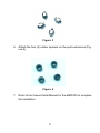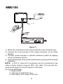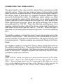
1
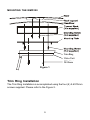
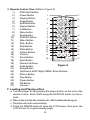
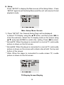
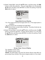
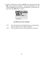
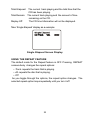
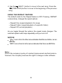
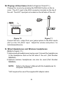
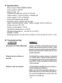
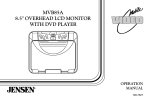
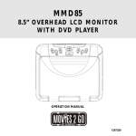
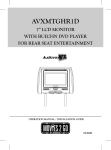
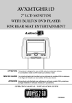
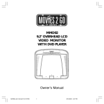
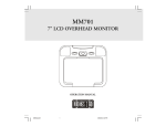
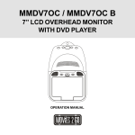
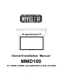
Owner/Installation Manual
MMD100
10" DROP DOWN LCD MONITOR & DVD PLAYER
1
Important Notices
Installation of overhead products requires careful planning and preparation. Be
extremely careful when working on a vehicle with side curtain air bags. Do not
route wires near any portion of the side curtain air bag assemblies. This includes
any anchor points in A, B, C or D pillars of the vehicle. Routing wires in these
areas or running wires by the side curtain air bags can prevent the side curtain air
bag from fully deploying which can result in personal injury to vehicle occupants.
If you have any questions regarding wire routing in a vehicle, please contact
Audiovox Technical Support at 1-800-225-6074.
When connecting power and ground in a mobile video installation ensure that the
ACC wire is fused at the point where it is connected to the vehicle ACC wiring.
Failure to do so can result in damage to the vehicle if a short circuit develops
between the vehicle connection point and the mobile video product.
An LCD panel and/or video monitor may be installed in a motor vehicle and visible
to the driver if the LCD panel or video monitor is used for vehicle information,
system control, rear or side observation or navigation. If the LCD panel or video
monitor is used for television reception, video or DVD play, the LCD panel or video
monitor must be installed so that these features will only function when the vehicle is in "park" or when the vehicle's parking brake is applied.
An LCD panel or video monitor used for television reception, video or DVD play
that operates when the vehicle is in gear or when the parking brake is not applied
must be installed to the rear of the driver's seat where it will not be visible, directly
or indirectly, to the operator of the motor vehicle.
Licensed under one or more of the following patents,
Patent NOS. 5,775,762 and 5,927,784
2
NOTE:
This product incorporates copyright protection technology that is protected by
method claims of certain patents and other intellectual property rights owned by
Macrovision Corporation and other rights owners. Use of this copyright protection
technology must be authorized by Macrovision Corporation , and is intended for
home and other limited viewing uses only, unless authorized by Macrovision Corporation. Reverse engineering or disassembly is prohibited.
Warnings
Do not use any solvents or cleaning materials when cleaning the video monitor.
Do not use any abrasive cleaners, they may scratch the screen.
Use only a lightly dampened lint free cloth to wipe the screen if it is dirty.
Lock the LCD screen in the fully closed position when not in use.
Before putting on headphones always adjust the volume setting to the lowest
position.
Remember to leave the dome light switch in the off or auto positions when the
vehicle is unattended, as the dome lights, if left on, can drain the vehicle’s battery.
Do not put pressure on the screen.
3
A. Introduction
Thank you for selecting the MMD100. The main features include a
10" Wide Screen (16:9 Aspect Ratio) Liquid Crystal Display (LCD)
monitor and a built-in DVD player. The unit applies the latest state of
the art electronics. The unit is constructed to provide years of reliable, trouble-free service. Please read the entire instruction manual
supplied with this product prior to operation. The documentation will
assist you in installing the system properly to obtain the best equipment performance. Please store this manual for later use.
B. Cautions and Warnings
1. Installation
Ensure that the MMD100 is installed in accordance with the instructions and illustrations provided in this manual.
2. Objects and Liquids
Do not push objects of any kind into the unit through openings; do
not spill or spray liquid of any kind on or in the system (this may
result in a fire or electric shock). To ensure proper ventilation and
proper operation, never cover or block the ventilation slots and openings
3.Disassembly
Do not attempt to disassemble the cabinet. There is a risk of electric shock and/or exposure to Laser Radiation. Contact qualified
service personnel if your system is in need of repair.
4. Cleaning Unit
When cleaning, make sure the system is unplugged from the power
source. Do not use liquid cleaners or aerosol cleaners. Use a
cloth lightly dampened with water for cleaning the exterior of the
system only.
4
5. Disc
Do not use irregularly shaped discs such as heart or star-shaped
discs as they may cause the unit to malfunction. Do not stick paper, tape or glue on the disc. Do not expose the disc to direct sunlight or heat sources such as hot air ducts. Do not touch the surface of disc. Handle the disc by its edge. Clean the disc by wiping
the disc from the center out with a cleaning cloth. Remove the disc
from the unit and store it in its case after playing. Some playback
operations of discs may be intentionally fixed by software producers. Since this unit plays discs according to the disc contents the
software producers designed, some playback features may not be
available. Also refer to the instructions supplied with the discs.
C. CONTENTS
1. 10” LCD Monitor & DVD Player Combo
2. A/V Adapter Cable
3. Hardware Package
4 pcs M4 x 8 mm Machine Screws
4 pcs M2.6 x 10 mm Screws
4 pcs Post Extension
4 Rubber Spacers for Post Extensions
4. Remote Control
5. Mounting Plate
6.Trim Ring
7. Owner/Installation Manual
5
D. Installation and Powering
TOOLS REQUIRED:
#2 Phillips Screwdriver
#1 Phillips Screwdriver
Utility or Razor Knife or Shears
Wire Strippers
Upholstery hook tool (for removal of panels as necessary)
Electrical Tape
Masking Tape
Multimeter (to verify 12 volt DC and continuity: Do not use a test light
or logic probe)
Marker pen – to mark headliner
Scribe (to mark trim ring if used)
Misc. electrical connectors (to connect to vehicle power source).
Requirements will vary from vehicle to vehicle.
GENERAL INSTALLATION APPROACH:
1) Decide upon system configuration and options that will be installed
(i.e.: what components, VCP, Tuner, RF Modulator/external amp, remote headphones, DVD, etc.).
2) Review all manuals to become familiar with electrical requirements
and hook ups.
3) Decide upon mounting locations of all components and method of
mounting.
4) Prep the vehicle by removing any interior trim necessary to gain access to vehicle's wiring as well as all areas where interconnecting
wire harnesses will need to be located. If any access holes need to
be cut into the vehicle (headliner, other trim components etc.), this
should be done now as well.
6
5) Route the wiring harnesses throughout the vehicle as necessary.
(Refer to the Wiring Diagrams on page 10 of this manual as well as
the wiring instructions for the individual components and accessory
options being installed). Be sure that all wiring is protected from
sharp edges and is routed in such a manner that it will not be pinched
when all components and interior trim are fully installed. Be sure to
leave enough slack in the wiring at each component to allow working
room.
Note:
If the vehicle is equipped with Side Curtain Air Bags, do not
run wires in the vacinity of the Side Curtain Air Bags.
6) Remove all A/V system components from their packaging and place
them loosely in the vehicle at their respective locations.
7) Connect all components together (electrically) and verify proper operation of all system functions. Note: This is best done BEFORE
components have been permanently mounted.
8) After verifying proper operation of the system, proceed to mount each
of the components.
9) When all components are mounted, recheck the entire system again
to ensure that no wiring was pinched or connected improperly during final installation.
7
Note: The MMD100 video system is only intended for an overhead,
drop down installation. It is not intended for seat back or any other
type of mounting. The hinging mechanism is designed for horizontal, drop down use only.
VEHICLE PREPARATION:
1) Locate an accessory power source (+12v when key is in the ACC.
and run positions, and 0v when key is off). Generally, this wire can
be found at the ignition switch or fuse-box.
2) The mounting method and location will vary from vehicle to vehicle,
so this manual will only focus on the installation of the video monitor
and related console accessories.
3) Generally, the best location for the video monitor is where the vehicle's
factory dome light is installed. The monitor should be located in
such a manner that it can be comfortably viewed by rear seat passengers. NEVER INSTALL THE MONITOR IN A PLACE WITHIN THE
DRIVER'S VIEW. THIS IS NOT ONLY DANGEROUS, BUT IT IS
ALSO ILLEGAL.
4) Once the mounting location of the monitor has been determined,
there may be additional preparation work necessary, depending on
the vehicle structure and installation method. Some of the steps
that may be required are:
A)
B)
Removal of the vehicle's dome light.
The headliner may need to be trimmed.
8
MOUNTING THE MMD100
Trim Ring
Video Unit
M4
8mm
M4¡Á8mm
Figure 1
Trim Ring Installation
The Trim Ring Installation is accomplished using the four (4) 2.6X10mm
screws supplied. Please refer to the Figure 2.
9
A
A
A
A
Figure 2
1. Place the MMD100 on a soft surface with the rubber gasket
facing up. Use care to avoid scratching the unit’s exterior surface.
2. Take off the rubber ring.
3. Place the trim ring on the unit and note the location of the four
mounting screws.
4. Attach the trim ring to the unit using the longer four (4) 2.6 X
10mm screws supplied.
5. Attach the four (4) post extensions to the bracket (Figure 3).
10
Figure 3
6. Attach the four (4) rubber spacers on the post extensions (Figure 4).
Figure 4
7. Refer to the Owner/Install Manual for the MMD100 to complete
the installation.
11
MMD100
Antenna
Y
Figure 5
1) Make the connections to the vehicle with the 5 pin wiring harness.
2) Connect the 5 pin harness to the mating connector on the Video
Monitor.
3) Connect power harness to vehicle's electrical system by tapping
into an accessory hot line.
4) Verify all functions of the system before final mounting of the finished
assembly.
NOTE: A VCP or other A/V Component can be connected to the
video monitor system using an RCA A/V cable. This second harness would plug into the AV1 inputs or AUX jack.
A/V Source Definitions :
1 = Built-in DVD
2 = AV1 input ( VCP, DVD, etc )
3 = AV2 Input ( VCP, Game, DVD, etc )
12
CONNECTING THE DOME LIGHTS
The dome lights in the video monitor require three connections to the
vehicle's wiring. There are two common types of dome light circuits
used, positive or negative switched. Positive systems supply voltage to
the interior lights to turn them on, negative switched systems apply
ground to illuminate the bulbs. To determine which system you have
you must locate the wires at the dome light. On a positive switched
system, with all the doors closed and the lights out, both wires at the
dome light will rest at ground. When the light is activated, one of these
wires will switch to +12V DC. This is the vehicle's switching wire. On a
negative switched system, with all the doors closed and the lights out,
both wires at the dome light will rest at + 12V DC. When the light is
activated, one of these wires will switch to ground. This is the switching
wire.
For positive systems, connect the violet / brown (Lamp auto) wire to the
vehicle's switched wire. Then connect the red / black (lamp on) wire to
a fused constant 12 volt source and the black / red (lamp common) wire
to a good ground. Positive systems are commonly found on Ford vehicles.
For negative systems, connect the violet / brown (Lamp auto) wire to
the vehicle's switched wire. Then connect the red / black (lamp on) wire
to a good ground and the black / red (lamp common) wire to fused constant 12 volt source. Negative systems are commonly found on General Motors and import vehicles.
Note:
Some vehicles which incorporate transistorized control of the dome
light circuit, such as the 1999 Dodge Caravan, may require that the
violet / brown (Lamp auto) wire be connected to the door pin switch
wire, as the additional current draw of the Monitor's lights may not be
supported by the output of the vehicles body control computer.
13
Positive Switched Dome lighting
To
constant
+12vdc
Red / black - Lamp on
Black / red - Lamp common
Violet / brown - Lamp Auto
To 3 pin
connector
on Monitor
Factory Dome light circuit
To
constant
+12vdc
Factory Door ajar
switch or Body
Control computer
Figure 6
Negative Switched Dome lighting
To 3 pin
connector
Red / black - Lamp on
Black / red - Lamp common
Violet / brown - Lamp Auto
To
constant
Factory Dome light circuit
To
constant
Factory Door ajar
switch or Body
Figure 7
14
E. Controls, Indicators, and Connectors
1. Unit View (Refer to Figure 5)
Figure 8
1) Headphone Jack
2) AV 2 In
3) SD Card Slot
4) Auto/Off/On Dome Light Switch
5) Power Button
6) Picture
7) Volume 8) Volume +
9) FM Modulator Switch
10) Press Button
11) Dome Lights
12) IR Sensor and Infrared Transmitter
13) Stop Button
14) Reverse Scan Button
15) Forward Scan Button
16) Eject button
17) Play button
18) Disc Insertion Slot
15
2. Remote Control View (Refer to Figure 9)
1)
DVD /AUX Button
1
2)
Power Button
3)
Display Button
2
4)
Angle Button
5)
Subtitle Button
3
6)
Repeat Button
4
7)
A-B Button
5
8)
Menu button
6
9)
Slow Button
7
8
10)
DVD/SD Button
9
11)
Skip+ Button
10
12)
Skip- Button
11
13)
Stop Button
12
14)
Wide Button
13
14
15)
Picture Button
16)
Volume 15
17)
Zoom Button
16
18)
Eject Button
19)
Numeric Buttons
Figure 9
20)
Audio Button
21)
Setup Button
22)
Up/Down/Left/FF/Right /REW/ Enter Buttons
23)
Return Button
24)
Play Button
25)
Pause Button
26)
FM Button
27)
Volume +
17
18
19
20
21
22
23
24
25
26
27
F. Loading and Playing a Disc
a. Turn the power on by pressing the power button on the unit or the
remote control. Select DVD using the DVD/AUX button on the remote.
b. Place a disc into the disc insertion slot with the label side facing up.
c. Playback will start automatically.
d. Press the PRESS button to open the LCD Screen, then pivot the
LCD Screen for a good viewing angle.
16
G. BASIC OPERATION
POWER
PLAY
SLOW
PAUSE
STOP
Turn the unit on/off
Start Playback
Play at 1/2,1/4,1/8, or 1/16 normal speed
Still Picture
(1 time) Stop at the present playing point /
(2 times) Stop playing
Scan forward at 2, 4, 8, 16, or 32 times norFORWARD
mal speed
Scan backward at 2, 4, 8, 16, or 32 times
REVERSE
normal speed
UP/DOWN/LEFT /RIGHT Used for Menu Navigation
Confirm item or setting
ENTER
Select item or password setting
NUMBERS
Not used in this model
RETURN
Display the root menu of the disc
MENU
Repeat playback of a title, chapter, or track
REPEAT
Repeat a specific portion from point A to
A-B
point B of the disc
Display disc information (title, chapter, track,
DISPLAY
time, etc.)
Change the angle on a scene
ANGLE
Select the subtitle language and turn it on/
SUBTITLE
off
Select the audio language
AUDIO
Enlarge an image to 2 ,3, or 4 times the
ZOOM
original size
Display the setup menu to select and set
SETUP
items, and exit the setup menu.
Source selection DVD, AV1, AV2
DVD/AUX
Eject disc
EJECT
Brightness/Contrast/Tint/Color
PICTURE
Reduce volume/Lower picture setting
VOLUMEIncrease volume/Raise picture setting
VOLUME+
Previous chapter/track
SKIPNext chapter/track
SKIP+
Source selection DVD, SD
DVD/SD
17
H. Setup
Press ‘SETUP’ to display the Main screen of the Setup Menu. Press
‘SETUP’ again to exit the Setup Menu and the unit will resume it’s last
playback mode.
Main Setup Menu Screen
1) Press “SETUP”, the ‘General Setup Page’ will be displayed.
a).Select ‘TV Display’ using the S/T button, and then press XX to
enter the submenu. Select the TV display mode on the screen using
S/T, and press ENTER to confirm the setting. Press WW to return.
* Normal/PS: When the player is connected to a normal TV, and a wide
picture is shown on the full screen.
* Normal/LB: When the player is connected to a normal TV, and a wide
picture is shown on the screen with a black strip at both the top and
bottom of the screen.
* Wide: When the player is connected to a wide screen TV, a wide
picture is shown on the full screen.
TV Display Screen Display
18
b).Select ‘Angle Mark’ using the S/T button, and then press the XX
button to enter the submenu. Choose Angle Mark on or off using the
S/T button and then press ENTER to confirm the setting. Press the
WW button to return.
Angle Mark Screen Display
* On: The screen will show the angle mark icon. (*If an angle option is
available).
* Off: The screen will not display the Angle Mark
NOTE: Not all discs contain above features. The above features are
disc dependent.
d).Select ‘Screen Saver’ using the S/T button, and then press the XX
button to enter the submenu. Choose Screen Saver on or off using
the S/T button and then press ENTER to confirm the setting. Press
the WW button to return.
Set Screen Saver
Screen Saver Screen Display
*On: Enables screen saver
*Off: Disables screen saver
*NOTE: The DVD player will enter the Screen Saver mode after approximately three minutes if the same image remains on the screen.
19
e). Select ‘Last Memory’ using the S/T button and then press the
XX button to enter the submenu. Choose Last Memory on or off
using the S/T button and then press ENTER to confirm the setting. Press the WW button to return.
Last Memory Screen Display
*On:
*Off:
The unit will return to the last position on the disc when
power is cycled, but not if disc is ejected.
The unit will not return to the last position on the disc.
20
2) Select “Video Quality Setup”by using the WW/XX button, press ENTER
to enter the video quality setup page.
Video Quality Setup Screen Display
a) Select ‘Brightness’ by using the S/T button, then press ENTER.
To change the Brightness, press the WW/XX button. To exit ‘Brightness’ setting, press ENTER again to return the main Menu.
Brightness Screen Display
21
b).Select ‘Contrast’ by using the S/T button, then press ENTER. To
adjust the Contrast, press the WW/XX button.
Contrast Screen Display
To exit ‘Contrast’ Setting, press ENTER again to return the main Menu.
c).Select ‘Saturation’ by using the S/T button, then press ENTER. To
adjust the Saturation, by press the WW/XX button.
Saturation (Color) Screen Display
To exit ‘Saturation’ setting, press ENTER again to return to the main Menu.
d).Select ‘Hue’ by using the S/T button, then press ENTER. To adjust
the Hue, press the WW/XX button.
Hue (Tint) Screen Display
To exit ‘Hue’ Setting, press ENTER again to return the main Menu.
22
3).Select “Password” using the WW/XX button, then press ENTER and
press the XX button to enter the submenu.
Password Setup Page Screen Display
Press ENTER to enter the Password Change Page. Input the Old
Password or the Default Password (Default 3308), followed by entering the New Password, and the Confirmed New Password. Press
ENTER to accept the change.
Password Change Page Screen Display
NOTE: The Default Password is 3308. This password is always
effective even after you have selected your own password and
changed it. To avoid the possibility of others using the default
password to set the parental level and change the password, you can
record this default password in another area and delete it from this
manual. Some discs can be limited depending on the age of users
while some discs cannot.
23
4).With no disc inside the player select ‘Preference Page’ using the WW/XX
buttons, then press ENTER to enter the Preference Page.
a). Select ‘Audio’ using the S/T button, then press XX to enter the
submenu. Select the audio language you desire using the S/T
button, then press ENTER to confirm the setting. Press WW to
return.
Preference Audio Language
b). Select ‘Subtitle’ using the S/T button, then press XX to enter
the submenu. Select the desired subtitle language or Subtitle Off using
the S/T button, then press ENTER to confirm the setting. Press
WW to return.
Preference Subtitle Language
Note: Language and subtitle selection is only available for discs that
are recorded in the above listed languages. If the selected language
is not available the player will play and display on the screen the original recorded language contained in the disc. Some DVDs only allow
access to these options in the DVD root menu.
24
c). Select ‘Disc Menu’ using the S/T button, then press XX to enter the
submenu. Select the Disc Menu Language you desire using the S/T
button, then press ENTER to confirm the setting. Press WW to return.
Preference Menu Language
d). Select ‘Parental’ using the S/T button, then press XX to enter the
submenu.
1
2
3
4
5
6
7
8
KID SAFE
G
PG
PG- 13
PG- R
R
NC- 17
ADULT
Parental Preference Screen Display
Select the parental level you desire using the S/T button for discs
with lock-out function or multiple rating levels. These are listed from
the lowest level (1 Kid Safe) to the highest level (8 Adult). Enter a 4
digit password, then press ENTER to confirm the parental level setting.
NOTE: The level of 8 Adult is the factory default. Please also note
that not all discs support this feature. Overall responsibility resides with the supervising adult.
25
e). Select ‘Default’ using the S/T button, then press XX to enter the
submenu. Press ENTER to return all settings to the factory-set mode.
NOTE: The parental setting and password are not affected by the
default reset function and remain at their current values.
Def aul t
Reset
Load Fact or y Set t i ng
Loading Factory Setting
26
I. Menu
A DVD is divided into sections called titles and chapters. When you
play a DVD, a root menu of the disc will appear on the screen of your
TV or Monitor. The contents of the menu vary from disc to disc. Press
MENU during playback to display the menu. Some DVDs only allow
you to select disc playback options using the DVD root menu.
J. Display
1. PLAYING TIME AND REMAINING TIME
a. During playback press the ‘DISPLAY’ button to display the current Title Number (1), the total Number of Titles (2), the current
Chapter Number (3), the total Number of Chapters (4), and the
Playing elapsed Time for the title (5). The heading will remain
visible until the operator presses the DISPLAY button and cycles
back to Display Off.
Title, Chapter Number, and Time Screen Display
b. Each time ‘DISPLAY’ is pressed, one of the following options will
become available:
z
Title Elapsed: The elapsed time of the title
z
Title Remain: The remaining time of the title
z
Chapter Elapsed: The elapsed time of the chapter
z
Chapter Remain: The remaining time of the chapter
z
Display Off: The DVD’s time Information will not be displayed.
Title Elapsed
Title Remain
Chapter Elapsed
Chapter Remain
Display Off
27
2. ANGLE
During playback of a disc, press ‘ANGLE’ to display the available angles
for discs containing multi-angles*, with the current angle number (1)
and the total number of angles (2) displaying. Press ‘ANGLE’ to select
another angle, then press again to exit and return to the normal viewing angle. The angle information will disappear automatically if the
‘ANGLE’ button is not pressed again within 3 seconds.
*NOTE: Not all discs contain this feature.
Angle Screen Display
3. SUBTITLE
During disc playback press ‘SUBTITLE’ to select the subtitle language
you desire*, with the current Subtitle Language Number (1) and the
total Number of Subtitle Languages (2) displayed. If there are multiple languages press ‘SUBTITLE’ again to select another subtitle language. To turn subtitles OFF, press the ‘SUBTITLE’ button until ‘Subtitle Off’ is displayed. The Subtitle display will disappear automatically
if the ‘SUBTITLE’ button is not pressed again within 3 seconds.
Subtitle Screen Display
* Some DVDs only allow access to this function through the DVD menu
28
4. AUDIO
During playback press ‘AUDIO’ to select the audio language you desire*, with the current Audio Channel Number (1) and the total number
of Audio Channels (2) displayed. Press AUDIO again to select another audio language. The audio display will disappear automatically if
the ‘AUDIO’ button is not pressed within for 3 seconds.
Audio 1 / 2 : Ac3 5 . 1Ch
Audio Language Screen Display
* Some DVDs only allow access to this function through the DVD
menu.
5. ZOOM
During playback press ‘ZOOM’ to enlarge the picture by 2x, 3x, or 4X
with the current zoom multiple. (1) Press “zoom” once, the picture
will be enlarged 2X. (2) Press “zoom” a second time ,the picture will
be enlarged 3X. (3) Press “zoom” a 3rd time ,the picture will be enlarged 4X. (4) Press “zoom” a 4th time ,the picture will return to normal size.
Zoom Screen Display
29
6. A-B REPEAT
a. During playback press ‘A-B’ to set the Starting Point A.
A-B Repeat Starting Point Screen Display
b. Press ‘A-B’ a second time to set the Ending Point B. The player will
repeatedly play the part between Point A and Point B.
A-B Repeat Ending Point Screen Display
c. Press ‘A-B’ a third time to cancel A-B repeat and resume normal
playback.
Repeat Off
A-B Repeat Cancelled Screen Display
30
7. REPEAT
During playback each time REPEAT is pressed, the following modes
will become available:
Chapter
Chapter: Repeat the current chapter
Title: Repeat the current title
All: Repeat all chapters and titles
Off: Resume normal playback
Off
Title
All
DVD Repeat Mode
The ‘Chapter’ repeat display is shown below for example:
Chapter Repeat Screen Display
K. Playing Audio CDS
When playing an audio CD press the DISPLAY button repeatedly on
the remote to view time information. The options below appear on
screen display circularly to show you what information is available
using this function.
Single Elapsed
Single Remain
Total Elapsed
Total Remain
Display Off
CD Display Mode
Single Elapsed: The current track playing and playing time of that
track will display on the screen.
Single Remain: The current track playing and the amount of time
left.
31
Total Elapsed: The current track playing and the total time that the
CD has been playing.
Total Remain: The current track playing and the amount of time
remaining on the CD.
Display Off:
The CD time Information will not be displayed.
Take ‘Single Elapsed’ display as a example:
Single Elapsed Screen Display
USING THE REPEAT FEATURE
The default mode for the Repeat feature is OFF. Pressing REPEAT
consecutively changes the repeat options:
• Track- repeats the track that is playing.
• All- repeats the disc that is playing.
• Off
As you toggle through the options, the repeat option changes. The
selected repeat option loops repeatedly until you turn it off.
32
L. Playing MP3 Discs
MP3 is a format for storing digital audio. An audio CD-quality song is
compressed into the MP3 format with very little loss of audio quality
while taking up much less disc space. CD-R /RW discs that have
been encoded in MP3 format are compatible with this system.
MP3 MENU Screen Display
When an MP3 disc is inserted into the unit, the menu screen appears
automatically. You can use the menu screen to select your desired
folders and songs or the system plays the songs in the order they
were burned onto the disc.
1. Press the or button to choose a folder from the folder list
on the left side of the screen.
2. Press ENTER to select the highlighted folder. The songs available in the folder will be listed.
3. Use or button to choose a song from the list. Press ENTER to select and begin playback of the highlighted song.
33
4. Use the
( NEXT ) button to move to the next song. Press the
(PREVIOUS) button to move to the beginning of the previous
song.
USING THE REPEAT FEATURE
The default mode for the Repeat feature is OFF. Pressing REPEAT
consecutively changes the repeat options:
• Repeat One (repeat playback of a song)
• Repeat Folder (repeat playback of a specific folder)
• Repeat Off (normal playback)
As you toggle through the options, the repeat mode changes. The
selected repeat mode loops repeatedly until you turn it off.
NOTICE
“
” icon in front of a file name indicates that this is a folder, not an
MP3 file.
“MP3” icon in front of a file name indicates that this is an MP3 file.
Note:
Due to the company’s policy of constant improvement and technical refinement, the company reserves the right to change or alter software.
34
M. Playing a Video Game (Refer to Figures 10 and 11.)
Change the source by pressing the DVD/AUX button on the remote. The AV1 input is the RCA connectors located on the top of
the unit. The AV2* input jack is located on the left side of the unit.
*
Figure 10
Figure 11
Connect the A/V output from your game system to the RCA inputs
(AV1) or the 1/8 (AV2)* input. Adjust the volume and picture for
individual preference.
N. Wired Headphones and Wireless headphones
(Refer to Figure 11.)
1.Optional wired Headphones may be used. Connect the headphones
to the Headphone Jack on the left side of the unit (Part Number
MMWHS).
2.Optional wireless headphones can also be used (Part Number
MMIRHS).
NOTE:
Refer to the Owner’s Manual with the headphones for
complete instructions.
*AV2 requires the use of the supplied AV adapter cable.
35
O.Wireless FM Modulator
The MMD100 is equipped with built-in wireless FM Modulator*, that allows you to listen to the MMD100 audio signal by tuning your vehicle’s
radio to the selected frequency (88.1, 88.3, 88.5, 88.7 or 88.9 MHz).
First, Press the FM button on the player, The “FM ** MHz” will appear
on the screen. Then use the FM button on the remote control to select
the frequency you desired. Select the same frequency on the vehicle’s
radio. Adjust the vehicle’s radio volume to a comfortable listening level.
Press the FM button repeatedly until FM OFF is displayed when the
FM Modulator is not used .
*NOTE: In certain areas where there are a large number of FM radio
stations (e.g. large cities, urban areas), the reception of the FM signal
from the overhead pod may not be satisfactory, resulting in static,
distorted sound or signal bleed thru from strong local radio stations.
This is not a defect in the product, but the result of a stronger local
radio station overpowering the wireless FM transmitter in your overhead pod.
Design and Specification are subject to change for product
improvement without notice
36
P. Specification
Disc format: DVD/CD/MP3/JPEG
Color system: NTSC
Screen size: 10”
Frequency response: 20 Hz to 20 kHz
Video output: 1 Vp-p/75 Ohm, unbalanced
Audio output: 1.4Vrms/10kOhm
Audio S/N: Better than 60 dB
Dynamic range : Better than 85 dB
Laser: Semiconductor Laser, Wave Length: 650 nm/790 nm
Power source: DC 12V
Power consumption: 18 W
Operating temperature: 5~35°C
Storage temperature: -20~60°C (4~140°F)
Weight:1.47Kg
Dimensions (W x H x D): 276.0 x 235.0 x 47.5 mm(10.9” x 9.3” x 1.9”)
Q. Troubleshooting:
SYMPTOM:
REMEDY:
No power at Video Monitor
-Verify +12 VDC on the Red wire at 2 pin
Power Harness behind video monitor. Verify
ground connection with continuity test from
known good ground to black wire at 2 pin
Power Harness.
Power but no video or
sound
-Verify that the correct source is selected
(i.e.: DVD, AUX) Verify that the source is
on and playing a known good media (such
as a DVD). Verify connections at both ends
of the harness.
Picture, but no sound
-Verify that the headphones are turned on;
check headphone batteries.
Make sure the FM modulator and the vehicle radio are set to the same FM station.
For wired headphones verify that the
volume is turned up.
37
12 MONTH LIMITED WARRANTY
Applies to Movies To Go Mobile Video Products
AUDIOVOX ELECTRONICS CORP. (the Company) warrants to the original retail
purchaser of this product that should this product or any part thereof, under normal use
and conditions, be proven defective in material or workmanship within 12 months from
the date of original purchase, such defect(s) will be repaired or replaced with
reconditioned product (at the Company's option) without charge for parts and repair
labor. A game controller, if supplied, is similarly warranted for ninety (90) days.
To obtain repair or replacement within the terms of this Warranty, the product is to be
delivered with proof of warranty coverage (e.g. dated bill of sale), specification of
defect(s), transportation prepaid, to the Company at the address shown below.
This Warranty does not extend to the elimination of externally generated static or noise,
to correction of antenna problems, to costs incurred for installation, removal or
reinstallation of the product, or to damage to digital memory/media devices, gaming
devices, discs, speakers, accessories, or vehicle electrical systems.
This Warranty does not apply to any product or part thereof which, in the
opinion of the Company, has suffered or been damaged through alteration,
improper installation, mishandling, misuse, neglect, accident, or by removal or defacement of the factory serial number/bar code label(s). THE
EXTENT OF THE COMPANY'S LIABILITY UNDER THIS WARRANTY IS LIMITED TO THE REPAIR OR REPLACEMENT PROVIDED ABOVE AND, IN NO
EVENT, SHALL THE COMPANY'S LIABILITY EXCEED THE PURCHASE
PRICE PAID BY PURCHASER FOR THE PRODUCT.
This Warranty is in lieu of all other express warranties or liabilities. ANY
IMPLIED WARRANTIES, INCLUDING ANY IMPLIED WARRANTY OF MERCHANTABILITY, SHALL BE LIMITED TO THE DURATION OF THIS WRITTEN
WARRANTY. ANY ACTION FOR BREACH OF ANY WARRANTY HEREUNDER INCLUDING ANY IMPLIED WARRANTY OF MERCHANTABILITY MUST
BE BROUGHT WITHIN A PERIOD OF 24 MONTHS FROM DATE OF ORIGINAL PURCHASE. IN NO CASE SHALL THE COMPANY BE LIABLE FOR ANY
CONSEQUENTIAL OR INCIDENTAL DAMAGES FOR BREACH OF THIS OR
ANY OTHER WARRANTY. No person or representative is authorized to
assume for the Company any liability other than expressed herein in
connection with the sale of this product.
Some states do not allow limitations on how long an implied warranty lasts or the
exclusion or limitation of incidental or consequential damage so the above limitations
or exclusions may not apply to you. This Warranty gives you specific legal rights and
you may also have other rights which vary from state to state.
Audiovox Electronics Corporation, 150 Marcus Blvd., Hauppauge, New York 11788
1-800-645-4994
128-6429F
© 2007 Audiovox Electronics Corporation, 150 Marcus Blvd., Hauppauge, New York 11788
128-8287