1
•
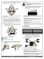
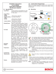
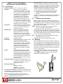
If necessary, you may remove the base from the cover by
pressing the two cover release tabs
inward while lifting the
base away from the cover.
5.0
Wiring
CAUTION
Note:
Only apply power after all connections have been
made and inspected. Do not coil excess wiring
inside detector.
Input power must use only an Approved Limited Power
Source. Some countries require that the Alarm and Tamper
Contacts be connected to a SELV (Safety Extra-Low
Voltage) circuit only.
POWER ALARM TAMPER
•
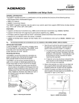
Route wiring as necessary to the rear of the base and through
the center hole.
Note:
•
Be sure all wiring is de-energized before routing.
Firmly mount the base. Depending on local regulations, the
base may be directly surface mounted using anchors, mollies,
or wing-nuts. It may also be mounted to standard 3.5 in.
octagonal electrical box. The detector may also be connected
directly to short lengths (short enough to avoid movement of the
detector) of ½ in. (1.27 cm) EMT.
Hint:
Mounting to removable ceiling tiles is not recommended
unless a sandwich is made of the base, ceiling tile, and a
back plate behind the tile.
-
+
-
+
NO
C
NC
T
T
M
•
Terminals 1 (-) & 2 (+): Power limits are 9 to 15 VDC. Use no
smaller than #22 AWG (0.8 mm) wire pair between the unit and
the power source.
•
Terminals 3 (NO), 4 (C), & 5 (NC): Alarm relay contacts rated
125 mA, 28 VDC maximum for DC resistive loads. Use
terminals 4 & 5 for Normally Closed circuits. Do not use with
capacitive or inductive loads.
•
Terminals 6 (T) & 7 (T): Normally Closed tamper contacts
rated at 28 VDC, 125 mA.
•
Terminal 8 (M): The memory mode requires a supply voltage
on Terminal 8 to be activated. See Section 9.1 for operation and
wiring information.
6.0
LED Operation
The detector uses a tri-color LED to indicate the various alarm and
supervision trouble conditions that may exist. See chart below.
LED
Steady red
Steady yellow
Steady green
Flashing red
Note:
Mounting Base
Wire entrance and/or EMT Mounting.
Mounting holes.
Tamper Post.
Wire entrance for surface mounting.
•
7.0
If ceiling tamper is desired, loosen the tamper post by cutting
the 3 tabs
and mount the post to the ceiling using a #8
screw .
Cause
Unit alarm
Microwave activation (walk test)
PIR activation (walk test)
Warmup period after power-up
During walk testing, the LED will light for the first
technology (microwave or PIR) and then light red to
indicate a detector alarm. The LED will not indicate
activation of the second technology by lighting its color.
Feature Selection
HIGH
ON
LOW
OFF
MAX
7.1
PIR Signal
Gain
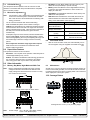
PIR Sensitivity Selection Pins
For selection, place the plug across the appropriate pins.
DS9370 Installation Instructions
•
Low Sensitivity (LO): The recommended setting for most
installations. This setting tolerates environment extremes. The
detector is shipped in Low Sensitivity mode.
•
High Sensitivity (HI): Use in locations where adequate catch
performance is not achieved in the Low Sensitivity mode. This
setting tolerates only minor environmental changes.
© 2002 Detection Systems, Inc. All rights reserved.
Page 2
P/N 48781C