1
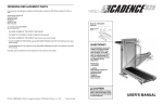
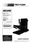
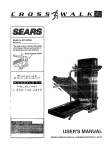
ER O
I I IIIIIIIIIII IIII II I I
II
SE / S
Model No. 831_9_64
Serial No.
The sedal numberis foundinthe location
shownbelow.Write the serialnumber in
theSPaCeabove for futurereference.
Sedal Number
E_X
E£: RC
I S
E_
EQUIPMENT
HELPLINE!
1-800-736-6879
USER'S MANUAL
SEARS, ROEBUCK AND CO, HOFFMAN ESTATES, IL 60179
TABLE OF CONTENTS
IMPORTANT
PRECAUTIONS
...................
ASSEMB'_'
.......... :::: ::
°1_
•
1oooo
.
IolqoooleQo=oog_
:::: ::
,o
OPE_TION
AND ADJUSTMENT .................
HOW TO FOLD AND MOVE THE TI:I_DMIIA......
TROUBLE,.SHOOTING
.........................
CONDITIONING GUIDELINES ..........................................
ORDERING REPLACEMENT PARTS • =.o ,,,,t
• • •
FULL 90 DAY WARFI.q_
...............
°°o
o.°.
°_°o
o_
! ........."........7
••
.......
10
II
•
•
....
12
.................
14
.
.
...........
Back Cover
••
°
aqa•
Back Cover
•
.
,,,_•,_
Q o J ...
*•I*Q
Q °
*o_o
Note: A HARDWARE IDENTIFICATION CHART, an EXPLODED DRAWING, and a PART UST and am attached
to the center of this manual. Please save them for future reference.
IMPORTANT PRECAUTIONS
2
Thedecalshownat the righthasbeen
placedon your treadmill.If the decalis
missing_or if it is not legible,pleasecall
our toll-freeHELPLINE
to ordera freereplacementdecal(seethe backcoverof
this manual).Applythe decalin the location shown.
AWARNING!
• Storage latch must be
fully engaged before
treadmill
is moved or
stored.
° °II
© 1
° °11
3
BEFORE YOU 13EGIN
Thank you for selecting the PROFORk, P CROSSWALK SI treadmill. The CROSSWALK SI treadmill
blends advanced technology with Innovative design to
let you enjoy an excellent form of cardiovascular exercise In the convenience and pdvacy of your home.
For your benefit, read this manual carefully before
using the treadmill. If you have additional questions,
please call our toU-free HELPUNE at 1-800-736-6879,
Monday through Saturday, 7 a.m. until 7 p.m. Central
Time (excluding holidays). To help us esslst you,
please note the product model number and Serial number before calling. The model number of the treadmill
is 831.297364. The serial number can be found on a
decal attached to the treadmill (see the front cover of
this manual for the location).
Before reading further, please mvtew the drawing
below and familiarize yourself with the pads that are
labeled.
Rack
"Bottle
Holder(Water
Boffieisnct
AccessoryTray
Induded)
Upper Body
Arms
Handrails
FRONT
WalldngBelt_
Foot Rails
BACK
RIGHT SIDE
Rear Roller
Adjustment Bolt
4
Platform
ASSEMBLY
CAUTION: Read and follow step I below before rernovlng the restraining Ue (sep cl_'a_ng "1).ff the restraining tie Is removed prematurely, serious bodily injury may result. Assembly requires _v/o people.. Set the treadmill in a cleared area and remove the packing materials except for the restraining tle"Do not dispose of the
packing materials until assembly Is completed. Use the HARDWARE IDENTIRC_.TION CHART in the center of
this manual to identify the parts used in assembly. Assembly requires the Included allen wrench L==-, a
phillips screwdriver ..==_,
and two adjustable wrenches G_==:_.
1. Slide the Left Upright (1) onto the left side of the Base
(59). It may be necessary to firmly push down on the
Left Upright until it Is fully seated on the Base.
Remove the restraining tie from the Base.
Attach the left handrail to the Base (59) with a Handrail
Bolt (93), 3/8" Washer (67), and Handrail Nut (4). Do not
tighten the Handrail Bolt yeL Using the allen wrench,
tighten two Upright Screws (63) with two of the four
Updght Washers (111) intothe Left Updght (1) and Base.
Restralnlng
2. Slide the Right Upright (44) onto the right side of the
Base (59). It may be necessary to firmly push down
on the Right Upright until it is fully seated on the
Base. Be careful not to pinch the Wire Harness (25)
between the Right Updght and the Base.
Attach the right handrail to the Base (59) with a Handrail
Bolt (93), 3/8" Washer (67), and Handrail Nut (4). Do not
tighten the Handrail Bolt yet. Using the allen wrench,
tighten two Updght Screws (63) with the remaining Upright
Washers (111) into the Right Upright (44) and Base.
Hand tighten the Handrail Nuts (4) used in steps I and 2.
Using a wrench, tighten the Handrail Bolts (93) used in
steps I end 2.
Remove the wire ties (not shown) attaching the Console
Base (9) to the Right Upright (44).
3. Set the Console Base (9) on the Left and Right Updghts
(1, 44).
While one person carefully fesds any slack Wire Hamess
(25) down into the Right Upright (44), a second person
should carefully pull the slack Wire Hamess from the
lower end of the Right Upright.
Attach the Console Base (9) with four Screws (75).
Align the holes in the Book Rack (62) with those in the
Console Base (9). Attach the Book Rack to the Console
Base with four Screws (75) as shown.
75
4. With the help of a secondperson, carefully lower the Left
and Right Uprights (1, 44) until the handrails are resting
on the floor.
.
•
44
59
Attach six Base Pads (57) to the bottom of the Base (59)
in the indicated locations. Note: An extra Base Pad may
be included.
.
(See drawing 4 above.) With the help of a second person,
raise the Left and Right Uprights (1, 44) until the Base
(59) is resting flat on the floor.
Before moving the treadmill, see HOW TO MOVE THE
TREADMILL on page 11.
Remove the Resistance Knob (97), 3/8" Washers (67),
Spdng Washer (5), Thrust Washers (101), Thrust Bearing
(102), and Resistance Cone (98) from the Resistance
Boll (105). Be sure to keep all parts in order. Insert one
of the Upper Body Arms (96) into the Resistance Cone
(98), making sure that it is turned as shown. Slide all
parts back onto the Resistance Boll (105). Refer to the
HARDWARE IDENTIFICATION CHART to make sure
So
Body
Arm must be
tumed in this
direction
105
104
--96
that all parts are in the correct order. Tighten the
Resistance Knob (97) onto the Res!stance Boll
102
Insert two Resistance Bracket Bolts (107) with Bracket
Washers (70) into the Left Updght (1). Slide two Star
Washers (103), a Spacer (106), and two more Star
Washers (103) onto the Bolts. Tighten the Bolts into the
:Resistance Bracket (104). (Note: It may be necessary to
loosen the Resistance Knob [97] and pivot the
Resistance Bracket.)
97
Attach the other Upper Body Arm (96) as descn'bed
above. Make sure that both Upper Body Arms are in the
position shown on page 4. Feed the slack Wire Harness
(25) into the Base (59).
.
6
Remove the backing from the Adhesive Clip (77). Press
the Adhesive Clip onto the Rear Roller Endcap (78) in the
indicated location. Press the Allen Wrench (76) into the
Adhesive Clip.
Make sure that all parts are tightened before you use the
treadmill. Note: To protect the floor or carpet, place a
mat under the treadmill. For information on ordering a
mat, see REPLACEMENT PARTS on the back cover.
7
78
76
OPERATION AND ADJUSTMENT
THE PERFORMANT LUBE TM WALKING BELT
Your treadmill features a walking belt coated with
PERFORMANT LUBE TM, a high-performance lubricanL
IMPORTANT: Never apply silicone spray or other
substances to the walking belt or the walking platform. They will detedorate the walking belt and
cause excessive wear.
electric shock. This pro_uct_i_s_pqulpped with a cord
having an equlpment-grodndi_g conductor and a
grounding plug. Plug,the po_er cord:into a surge
protector, and plug=the surge protector into an alP
proprfate outlet that Is properly Installed and
grounded in accordance with all local codes and
ordinances.
This product is for use on a nominal 120-volt circuit,
and has a grounding plug that looks like the plug illustrated in drawing I below. A temporary adapter that
looks like the adapter illustrated in drawlng 2 may be
used to connect the surge protector to a 2-pole receptacle as shown in drawing 2 if a propedy grounded outlet is not available.
HOW TO PLUG IN THE POWER CORD
The temporary adapter should be used only until a
properly grounded outlet (drawing 1) can be installed
by a qualified electrician.
The green-colored dgid ear, lug, or the like extending
from the adapter must be connected to a permanent
ground such as a propedy greu'nded outlet box cover.
Whenever the adapter is used It must be held in place
by a metal screw. Some 2-pole receptacle outlet box
covers are not grounded. Contact a qualified elsctdclan to determine if the outlet box cover is
Your treadmill, like any other type of sophisticated
electronic equipment, can be seriously damaged by
sudden voltage changes in your home's power..
Voltage surges, spikes, and noise interference can regrounded before using an adapter.
sult from weather conditions or from other appliances
being tumed on or off.
To decrease the possibility of your tread1
t Box
mill being damaged,
Treadmill I
always use a surge
,Grounding Pin
protector (not included) with your
treadmill.
Surge protectors are
sold at most hardware
stores and department
stores. Use only a ULlisted surge protector,
rated at 15 amps, with a
14-gauge cord of five
fdct or less in length.
Outlet
^_.
.
Grounded Outlet Box
Adapter
This product must be
grounded. If if should
malfunction or break
down, grounding provides a path of least resistance for electric current to reduce the risk of
.._
/_"
_>_
Groundin
Plug
Surge Protector
_etaL[Ug:rew_
7
DIAGRAM
OFTHECONSOLE
SpeedControl
Key
Pulse
Sensor
BATrERYINSTALLATION
STEP BY STEP CONSOLE OPERATION
Theconsolerequiresthree"AA" battedas(notincluded).Alkalinebatteriesarerecommended.
ToInstallbatteries,
openthebatterycoverunderthe
Before operating the console, make sure that the power
cord Is propedy plugged in. (See HOW TO PLUG IN
THE POWER CORD on page 7.) If there Is a thin sheet
of clear plastic on the face of the console, remove it.
console as shown below. Press three batteries into the
battery compartmenL
Make sure
Bakery
that the negCover
ative (-)
ends of the
batteries are
touching the
_iedes
springs.
Close the
battery cover.
8
MonitorDisplays
Next, step onto the foot rails of the treadmill. Rnd the
clip attached to the key (see the drawing above), and
slide the clip onto the waistband of your clothing.
Follow the steps on page 9 to operate the console.
[!
CALORIF.S/FATCAL"
Insert the key fully into the power sw_tch.
•
inserting the key will
not turn on the displays. The displays will
rum on when the
ON/RESET button is
,_-C)=
. ....
dlsptay--This display ,:,_ ;" b
shows the =tnnmxlrndte _! ,_
_'
•,
./L .r_.Tq
,_ ,.P_..4L_'_TCN.S.
numbers of calories and,_ I
fat calodes you have _ i"_1"
._,
burned. (See FAT
.CALORIES on page 14 for an explanation of fat
caiodes.) Every seven seconds, the display will
change from one number to the other. Arrows in the
display will indicate which number is currently
shown. Note: This display will also show your pulse
when the pulse sensor is used.
pressed or when the
walking belt Is started.
Note: If you just installed baRedes, the displays will already be on..
lg
I.,
&
Reset the speed control.
Slide the speed control
down to the RESET IXP
sition. Note: Each time
the walking belt Is
stopped, the speed
control must be moved
reset, if desired, by
pressing the ON/RESET
button,
The
B
to the RESET position
before the walking belt
can be restarted.
canbe
I
oH/ .=s_r
Measure your pulse, if desired.
To use the pulse
sensor, stand on
the foot rails and
Pulse
place your thumb
on the pulse sensor as shown. The
lg
Start the walking belt.
After you have moved the speed control to the
RESET position, slowly slide it upward until the
walking belt begins to move at slow speed.
Carefully step onto the walking belt and begin exercising. Change the speed of the walking belt as desired by sliding the speed control.
To stop the walking belt, step onto the foot rails and
slide the speed control to the RESET position.
B
Follow your progress with the monitor displays.
pulse sensor is
pressure-activated;
fully press down
the pulse sensor. Do not press too hard, orthe
clrculatton in your thumb will be restricted, and
your pulse will not be
detected. Next, slightly
raise your thumb until
(L,I
the head-shaped Indicator in the CALORIES/
FAT CALORIES/PULSE
Ind"
display flashes steadily.
Hold your thumb at this
level• After 5 to 10 seconds, your pulse will be
shown. Hold your thumb on the sensor for another
15 seconds for the most accurate reading. If the displayed pulse appears to be too high or too low, or if
your pulse Is not displayed, lift your thumb off the
sensor and allow the display to reset. Press down
again on the sensor as described above.
"dsPaYThs
I 1I
display shows the total
time that you have
Ft.
rl
IJ'2U
walked or run on the
treadmill.
_ME
°
This display shows the
total distance that you
have walked or run, in
miles.
SPEED display--This
display shows the speed
of the walking belt, in
miles per hour.
_"
I
Make sure that your thumb Is positioned as shown,
and that you are applying the prol_.r amount of pressure to the pulse sensor. Try the sensor several
times until you become familiar with it. Remember to
stand still while measuring your pulse.
_£".
DISTANCE
!
ul
r-ccnl
SPEED
I
r_
when
amand
flnlshed
walkingyou
belt
remove_xerclstng,
the key.
Step onto the foot rails,
stop the walking belt,
and remove the key
from the console. Store
stop the
,_.=,O _,._
HOW TO CHANGE THE INCUNE OF THE TREADMILL
the key In a secure
place. After the key is
removed, the displays
will remain on for
about flve minutes.
The incline of the treadmill can be changed by raising or
lowering the back end. Before changing the incline,
remove the key and unplug the power cord.
Note: Any time that the walking belt Is stopped
and no console buttons are pressed for five mlnutea, the displays will automatically turn off in
order to conserve the batteries.
HOW TO USE THE UPPER BODY ARMS
As you exercise on
the treadmill, you
can hold either the
handrails or the
To varf the intensity of your upper body exercise, the
resistance of the upper body arms can be adjusted. To
Increase the resistance, turn the resistance knobs dockwise; to decrease the resistance, turn the knobs counterclockwise.
Upper Body
Hold the
rear miler
endcap
with both
hands.
When the
back end
of the
treadmill is
in the low-
Hold the Rear
Incline
i
in these locations
est posilion, the incline is about 10%. Raise the back end until it
dicks into position. (Note: It may be necessary to shake
the treadmill slightly so that it dicks into position.) The
incline will then be about 5%. Raise the back end again
until it dicks into position. The incline will then be about
3%. To lower the back end, first raise it past the highest
position, and then lower it. CAUTION: Before exercising, push on the back of the treadmill to make sure
that the Incline legs are locked in position. Do not
place objects under the treadmill to change the incline; change the Incline only as described above.
upper body arms.
The upper body
arms are designed
•to exercise your
arms, shoulders,
and back for a total
body workout. Hold
one upper body
arm with each
hand, and move
them fomtard and
back a_ you walk
on the treadmill.
HOW TO FOLD AND MOVE THE TREADMILL
HOW TO FOLD THE TREADMILL
FOR ST()RAGE
Before folding the treadmill: unplug the power cord. Caution:
You must be abl e to safely lift 45 pounds (20 kg) In order
to raise, lower, or move the treadmill.
1. Hold the treadmill with your hands in the locations shown
at the right. To decrease the possibility of injury, bend
• your legs and keep your back straight. As you raise
the treadmill, make sure to lift with your legs rather
than your back. Raise the treadmill about halfway to the
vertical position.
10
Leg
2. Move your dght hand to the position shown and hold the
treadmill firmly. Raise the treadmill until th_ storage latch
doses over the frame guide. Make sure'that the storage
latch closes fully over the frame guide.
To protect the floor or carpet from damage, place a
mat under the treadmill. Keep the treedmlll out of direct sunlight. Do not leave the treadmill In the storage
position In temperatures above 85 ° Fahrenheit.
Closed
HOW TO MOVE THE TREADMILL
Before movlng the treadmlll, conved the treadmill to the storage position as described above. Make sure that the storage latch Is closed fully over the frame guide.
1. Hold the upper ends of the handrails. Place one foot on
the base as shown.
2. Tilt the treadmill back until it mils freely on the frontwheels.
Carefully move the treadmill to the desired location. Never
move the treadmill without tipping It back, or the base
pads may come off. To reduce the risk of Injury, use
extreme caution while moving the treadmill. Do not sttempt to move the treedmlll over an uneven surface.
3. Place one foot on the base, andcarefully lower the treadmill until it is resting in the storage position.
HOW TO LOWER THE TREADMILL
FOR USE
1. Hold the upper end of the treadmill with your dght hand as
shown. Uslng your left thumb, slide open the storage latch
and hold it open. Pivot the treadmill until the frame and
foot rail are past the storage latch.
2. Hold the treadmill firmly with both hands, and lower the
treadmill to the floor. To decrease the possibility of InJury, bend your legs and keep your back straight.
Front Wheels
TROUBLE-SHOOTING
Most treadmill problems can be solved by following the simple steps below. Rnd the symptom that applies, and follow the steps listed. If further assistance Is needed, call our toll-fres HELPUNE st 1-800-7366879, Monday through Saturday, 7 a.m. until 7 p.m. Central Time (excluding holidays).
1. SYMPTOM: THE POWER DOES NOT TURN ON
a. Make sure that the power cord is plugged into a surge protector, and that the surge protector is plugged into
a properly grounded outlet. (See HOW TO PLUG IN THE POWER CORD on page 7.) Use only a UL-listed
surge protector, rated at 15 stops, with a 14-gauge cord of five feet or less in length.
b. Afterthe powercord hasbeen pluggedin, make surethatthe key is fullyinsertedintothe console.(See step
1 on page 0.)
c. Check the circuit breaker located on the treadmill near the
power cord. If the switch protrudes as shown, the circuit
breaker has tdpped. To reset the circuit breaker, wait for five
minutes and then press the switch back in.
Ic
Tdppad
Reset
2. SYMPTOM: THE POWER TURNS OFF DURING USE
a. Check the circuit breaker located on the treadmill frame near the power cord (see 1. C. above). If the circuit
breaker has tripped, wait for five minutes and then press the switch back in.
b. Make sure that the power cord is plugged in.
c. Remove the key from the console.Reinsert the key fully into the console. (See step I on page 9.)
d. If the treadmill still will not run, please call our toll-free HELPUNE.
3. SYMPTOM: THE INCLINE SYSTEM STICKS
a. Raise the treedmgl to the storage position. (See HOW TO FOLD THE TREADMILL FOR STORAGE on
page 10.) Pivot the incline leg several times to break in the incline system.
4. SYMPTOM: THE WALKING BELT SLOWS WHEN WALKED ON
a. Use only a UL-listed surge protector, rated at 15 amps, with a 14-gauge cord of five feet or !ass in length.
b. if the walking belt is overtightened, treadmill performance may
decrease and the walking belt may be permanenUy damaged.
Remove the key and UNPLUG THE POWER CORD. Using the
allen wrench, tum bothrear roller aa'justment bolts counterclockwise, 1/4 of a turn. When the walking belt is properly tightened,
you should be able to lift each side of the walking belt 2-3
inches off the walking platform. The center of the walking belt
should just touch the walking platform. Be careful to keep the
walking belt centered. P!ug in the power cord, insert the key and
run the treadmill for a few minutes. Repeat until the walking belt
is properly tightened.
Rear Roller Adjustrnent Bolts
c. If the walking belt still slows when walked on, please call our toll-free HELPUNE.
5. SYMPTOM: THE TREADMILL
12
SITS UNEVENLY ON THE FLOOR
a. Make sure that the six base pads are attached to the treadmill (see assembly step 5 on page 6).
a. If thewa,dngbe1hu atdted_ thelatt,fkstremove_mkayend
UNPLUG THE POWER CORD. Using the 8/16" end of the alfen
wrench, turn the Id reef reht sdJustme_ bolt dodod_, and
the dght bolt ¢ounte,rdockwl_, 114 of a turn each. Se cemful not
to ove_ghten the w_ldng belL PI_ In the power cord, Insed the
key and run the tre_lmUl for a few minutes. Repeat u_l the
walking belt is centered.
b. If the walldng belt hes shifted to tbe dght, ltmt remove the key
end UNPLUG THE POWER CORD. Ulktg the _ 6° end of the
allen ranch, turn the Isft resr teem a_uatme_ bolt counterdoci_
and the dght boltdodo#cm, 1/4 of 8 turn each. Be
cereftd not to ovolitghton the walldng belt. Ptug In the power
cord, Incevtthe k_, and nm the tmldmll for a few minutes.
Repeat until the wslklng belt Is centered.
c. Lfthe watldng belt slips when _
on, aret remove the key
and UNPLUG THE POWER CORD. Using the 3/16" end of the
allen wrench, turn 1_4hrcer roller sdjustmont bolt8 dockw_e,
1/4 of a turn. When the wddng belt IS oom_tiy tightened, you
should be able to lifteach aide of the walidng belt 2-8 Inches off
the walklng-pistfomt. The center of the walking belt shouldjust
touch the walldng platform. Be cere(ul to keep the walking belt
centered. Plug in the power oord, inesrt the kay aed mn the
tmedmlU fer a few n.dnute-,.Repeat urdl h'_owddng belt is prop
ertyt_htened.
7. SYMPTOM: ONE OF THE UPPER BODY ARM8 SQUEAKS DURING USE
_ Corrastingthis problemrequires e small 8mount of white madne
grease, a_
at moat herdwem ator_.
Turn the _nce
Knob (97) oourttelckx:kwise Imtil It cwt be
removed. Remove the Reslslame Cone (08) end _o Upper
BodyArm(SS}.along_
the3/i!"Weshers(67),,Spd_
'.Nesher(5), Thrust Washers (101), end Thrust Bearing (102).
(Note: If the Resistance Sleeve [gg] comes out of the
Resistance Bracket [104], press it beck in.) Apply s _th layer of
white madne grease to the outer 8udoce of the Resistance Cone
(98). Reaitach 811parts in the older shown at the dgt_.
8. SYMPTOM: THE DISPLAYS OF THE CONSOLE DO NOT FUNCTION PROPERLY
a. Check the I_tttedes in the console. (See BAI"I"BRY INsTALLATION on page 8.) Most problems 8re the resuit of drained bettedee.
b. If the speed display dces not show 8 oorreot reading, remove the
key and UNPLUG THE POWER CORD. _
the trasdmil to
the storage pceltlon. (See HOW TO FOLD THE TREADMILL
FOR sTOP,AGE on page 10.) Remove the tour indicated screws.
Next, lower the treadmill. (See HOW TO LOWER THE TREADMiLL FOR USE on page 11). Remove the four screws from the
sides of the hood. Caratully slide the hood forward and remove it.
See page 14 for further Jnstru_ions.
t38)
on
a le
the Reed 8w_:h. Mal(e _m tim the gap bemm
the IkqlMt
and the Reed Switch Is _ut
1/8". ff nacemuy, IooMn the
Screw (18) and move tbe Reed Sw_ dohUY. P_UOhtenthe
8crow. Re.atta_ the heod (see 8. b. on pego 13), znd mn the
treadmill for a few minutes to check for s conect speed reading.
88-• 19/
1/8"-Top
View
CONDITIONING GUIDELINES
To findthe propor heart rate for you, first find your age
at the top of the chert (ages am rounded oti to the
nearest ten years). Next, find the three numbers below
your age. The three numbers ere your _
zone:
The lower two numbers are recommended heart rates
for let burning;,the higher number Is the recommended
heart rate for uroblc e_erclse.
Fat Burning
The followingfluidallnes will halp you to Idan your w(ercise program. Remember--these are general gukleVjles only. For .morndefalled exe_ise Intomlation, ob_n a reputa_e book or consult your physic,
EXERCISE INTENSITY
Whether your goal is to bum fat or to strengthen your
card'mvucular eystom, the key to luRdevfngthe desired results is to exercise with the pml_'lntensltY.
The proper Intensity leve; can be found by using your
heart rate as s guide. The chart below shows n_ornmended heart rates for fat burningand umblc oxer-
dse.(Thisdmrtisaisofoundontheoonsole.)
2O ._0
40
50
60
70
8O AGE
b.pm.
HEART RATE TRAINING ZONES
14
MAX.FAT
FATBURN
To bum fat effe_aly, you must exorcise at a m_wdy
low intemdtyk)vel for a sustained pedod _lme. Dudng
the _,st faw minutes of exemlse, your body uses euay
ac_mlble ca,-bohydrateca/or/es for enerw. Or4y after
the first few minutes does your body begin to use
stored fat ca/odes for energy. If your goal Isto bum fat,
a_ust the speed and Indlne of the VeadrnglunE your
he_ ra_ is nur one of the Iowor two numbem In y_r
tndn_tg zone. It nmy _dsobe bel_t_ to sst the speed
controlon Ibe console to FAT BURN to help you malnt_n _ proper _ntons,y _.
(See paO= 9.)
Aerobic Exercise
If your goal is to strengthen your .c_'lovucular eye.
tern, you_ exercise must be '_l_,oblc." Aerobic exercise
is aclivitythat requires Imge amounts of oxygen for
prolonged pedode of time. This Increases the demand
on the heaA to pump blood to the mmlcies, and on the
lungs to oxygenate the blood. For serobk: exercise,
adjust the speed and Indlne of the tmadmll untJiyour
heart rate Is near the Idghor number in your tndnlng
zone. It may also be halpfulto NI the apeed oontrol on
the_=onsoleto AEROBIC to help you maintain the
proper intensity level. (See page 9.)
Remove this HARDWARE IDENTIFICA.TIO_I CHARTi EX-PLODED DRAWING, and PART LIST from the _a!.
Save this page for future reference.
HARDWARE
IDENTIFICATION
CHART
The chad below is provided to help you Identify the small pads used in assembly. The number In parenthesis
below each part refers to the key number of the part. The second number refers to the quantity used in assembiy.
The drawing at the bottom of this page shows the small parts used In the upper body arm assembly;, use this
drawing for assembly step 6 on page 6. Important: Some parts may have been pre.essembled for shipping
purposes. If you cannot find a part In the parts bag, check to see If it has been pre-assembled.
3/8" Washer (67)-6
Thrust Bearing (102)-2
Spring Washer (5)-2
U©
Star Washer (103)-8
Upright Washer (111)-4
l©
Tilrust Washer 11011--4
_kkkkk_
Handrail Nut (4)-2
Screw (75)-6
Bracket Washer (70)-4
:B©
Handr_l Bolt (63)-2
u
_\\\\\\\\_J
Resistance Bolt (105)-2
Upright Screw (63)-4
D@
Resistance Bracket Bolt (107)--4
_\\\\\I
:
?
UPPER BODY
ARM ASSEMBLY
99
105
101
67
97
104
98
67
102
EXPLODED
DRAWINGuModel
No. 831.297364
_1196A
82
75
92
\
11
66
75
75
51
98
109
67
69
63
103
106
70
102
107
5
97
81
111
68
77
93
,27
4
91
7
_
76 _
67
16
70
74
t=---- 19
19
43
66
47
6
74
16
72 ¸
73
66
6
2O
_.
i
I
112 I
i! 124
25
I
28
84
\
17
69
5
6O
48
-55
67
103
30
""
104
105
45
47
,
,
46
t
j
25
111
93
IO0
56 6
4
.57
55
PART LIST--Model No. 831.297364
Key No. pa_ No. Qty.
I S&lq
1
_
2
132766
3
131240
4
105477
5
128005
6
119425
7
131161
8
129640
9
131606
10"
133961
11
119038
12
126134
13
124669
14
122812
15
014117
16
012056
17
120867
18
133963
19
120630
20
107503
21
130993
22
013578
23
NSP
24
013300
25
133964
26
133860
27
13.3333
28
133106
29
01 3322
30
109332
31
124695
32
130425
33
135527
34*
133968
35
126747
36
133413
37
133563
38
118153
39
100498
40
016029
41
108080
42 : 112609
43
014127
44
135222
45
133685
46
130868
47 " 013162
48
131639
49
127098
50
131738 °
51
129734
52
130251
53
133967
54
129004
55
013430
56
129642
57
129740
58
013547
59
135529
60
130822
1
1
1
2
2
8
1
1
1
1
1
1
1
1
1
2
1
1
20
1
1
2
1
4
1
2
8
4
4
1
1
1
1
1
1
1
1
1
1
2
2
1
3
1
2
2
18
1
2
1
2
2
1
1
2
2
7
3
1
1
Description
Left Upright
Front Frame Cover
Incline Latch
Handrail Nut
Spdng Washer
3/8" Lock NUt
Speed Knob
Speed Potentiometer
Console Base
Console
Key/Clip
Motor Belt
Power Cord
Motor Tension Washer
Motor Tension Star Washer
Incline Wheel Nut
Motor Tension Nut
Motor Hood
Small Screw
Motor Pivot Bolt
Choke
Incline Bolt
Frame
Anchor Screw
Wire Harness
15=WireTie
Cover Clip
Hood Anchor
Frame Cover Screw
Circuit Breaker
Grommet
Ground Wire
Left Foot Rail
Motor/Pulley/Flywheel/Fan
Pulley/Flywheel/Fan
Motor
Controller
Reed Switch
Magnet
4" Cable Tie
Ratchet Screw
Front Roller Adj. Bolt
Adjualment Washer
Right Updght
Upright Spacer
Base Wheel Bolt
Belly Pan Screw
Belly Pan
Belt Guide
Storage Latch
Storage Latch Spdng
Frdme Guide
Rear Frame Cover
Wire Harness Grommet
Upright Pivot Bolt
Base Wheel
Base Pad
Motor Tension Bolt
Base
Safety Cover Connector
Key No.Part No.
61
117806
62
131607
63
013484
64
124565
65
116927
66
013576
67
014132
68
121576
69
135528
70
014063
71
130501
72
052012
73
013523
74
013342
75
126996
76
128457
77
016028
78
132880
79
133845
80
130518
81
131605
82
120639
83
016057
84
131741
85
131749
86
128272
87
131751
88
.131689
89
129814
90
131704
91
116926
92
131753
93
124514 +
94
132051
95
105500
96
128598
97
126843
98
126828
99
126827
100
128271
101
102973
102
106896
103
014149
104
126773
105
126644
105
132583
107
132637
108
126960
109
127819
110
131562
111
014073
112
131090
#
114953
#
101897
#
107771
#
101896
#
134825
R1196A
Qty.
2
1
4
1
1
16
10
2
1
6
1
2
2
2
12
1
1
1
1
2
1
1
4
1
1
8
8
1
1
1
8
1
2
1
2
2
2
2
2
1
4
2
8
2
2
2
4
1
1
2
4
1
1
1
1
1
1
Deecdptlon
Incline Leg Wheel Bolt
Book Rack
Updght Screw
Ratchet Spdng
Wire Tie Holder
Latch-Frame Guide Screw
3/8" Washer
Roller Endcap Nut
Right Foot Rail
Endcap/Bracket Washer
Incline I_eg
Incline Leg Wheel
Rear Roller Endcap Screw
Adjustment Bolt
Screw
Allen Wrench
Adhesive Clip
-Rear Roller Endcap
Rear Roller
Incline Leg Spacer (long)
Latch Decal
Batten/Cover
8" Cable Tie
Walking Belt
Walking Platform
" Platform Screw
Isolator
Incline Leg Plate
Shock
Front Roller/Pulley
Releasable Cable Tie
Storage Latch Bracket
Handrail Bolt '
Frame Guide Spacer
Foam Gdp
Upper Body Arms w/Foam
Resistance Knob
ReSistance Cone
Resistance Sleeve
Incline Leg Spacer (shod)
Thrust Washer
Thrust Bearing
Star Washer
Resistance Bracket
Resistance Bolt
Resistance Bracket Spacer
Resistance Bracket Bolt
Base Plug
Frame Plug
Latch Pad
Updght Washer
Clamp
14" Blue Wire, 2 Female
14" White Wire, 2 Female
8" White Wire, Male/Female
4" White Wire, Male/Female
User's Manual
* Includes all parts shown in the box
# These parts are not illustrated
High Performance
Athletic Conditioning
;
Training Zone .Exqrci.se
=
if your goal is high performance athletic conditioning,
sot the speed control on the console to PERFORMANCE to help you maintain the proper intensity level.
(See page 9.) Note: Dudng the first few weeks of your
exercise program, keep your heart rate near the low
end of your training zone.
also until your hedrt rate.b in,y._r tlalra.ng zone mr zu
to 60 minutes. (Dudng theefirst _flawwebks of your exerrise program, do not keep yopc'heart r_te in your training zone for longer than 20 minutes.) Breathe regularly
and deeply as you exercise--never hold your breath.
HOW TO MEASURE YOUR HEART RATE
A Cool-down
To measure your heart rate, use the pulse sensor on
the console. (See page 9.) If your heart rate is too high
or too low, adjust the speed or incline of the treadmill
until your head rate is at the proper level.
Rnlsh each workout with 5 to _10minutes of stretching
to cool down. This will Incraese the flexibility of your
muscles and will help to prevent post-exercise problems.
Exercise Frequency
WORKOUT
GUIDELINES
Each workout should include three important pads:
A Warm-up
Begin with 5 to 10 _nutes of stretchingand light exerrise. Warming up increases the body temperature, heart
rate, and dmulation in prepemtlon for vigorous exercise.
SUGGESTED
To maintain or improve your condition, complete three
workouts each week, with at least one day of rest between workouts. After a few months, you may complete up to five workouts each week.
Remember, the key to success is to make exercise a
regular and enjoyable part of your everyday life.
STRETCHES
The correct form for several basic stretches is shown in the
drawings below. Move slowly as you stretch--never bounce.
1. Toe Touch Stretch
Stand wlth your knees bent slightly and slowly bend forward
from your hips. Allow your back and shoulders to relax as you
reach down toward your toes as far as possible. Hold for 15
counts, then relax. Repeat 3 times. Stretches: Hamstrings,
back of knees and back.
2. Hamstring Stretch
Sit with one leg extended. Bring the sole of the opposite foot
toward you and rest it against the inner thigh of your extended
leg. Reach toward your toes as far as possible. Hold for 15
counts, then relax. Repeat 3 times for each leg. Stretches:
Hamstrings, lower back and groin.
3.'Calf/Achilles
Stretch
With one leg in front of the other, reach forward and place your
hands against a wall Keep your back leg straight and your
back foot flat on the floor. Bend your front leg, lean forward and
move your hips toward the wall. Hold for 15 counts, then relax.
Repeat 3 times for each leg. To cause further stretching of the
achilles tendons, bend your back leg as well. Stretches:
Calves, achilles tendons and ankles•
8£ARS
The model number and serial number of your PROFORM* CROSSWALK SI treadmill are listed on a decal attached to the frame. See
the front cover of this manual to find the location of the decal.
Model No. 831.297364
QUESTIONS?
All mpiacament pads are ava, able for Immediate purchase or
special order when you visit your nearest SEARS Service Center.
To request service or to order parts by telephone, call the toll-free
numbers listed at the left.
If you find that:
• you need help assembling or
operating the PROFORM °
CROSSWALK SI treadmill
• a part Is missing
• or you need to Schedule repair
service
When requesting help or service, or ordering pads. please be pre-.
pared to provide the following Information:
• The NAME OF THE PRODUCT (PROFORM = CROSSWALK SI
treadmill)
• The MODEL NUMBER OFTHE PRODUCT (831.297364)
call our toll-free HELPLINE
1-800-736-6879
Monday-Saturday, 7 am-7 pm
Central Time (excluding holidays)
• The PART NUMBER OF THE PART (see the EXPLODED
DRAWING and PART UST included In this manual)
• The DESCRIPTION OF THE PART (see the EXPLODED DRAWING and PART UST Included In this manual).
REPLACEMENT
PARTS
If parts become worn and need
to be mpiaced, call the following
toll-free number
1-800-FON-PART
(1-800-366-7278)
FULL 90 DAY WARRANTY
For 90 days from the date of purchase, if failure occurs due to defect In matedal or workmanshlp In this
SEARS TREADMILL EXERCISER, contact the nearest SEARS Service Center throughout the United
States and SEARS will repair or replace the TREADMILL EXERCISER, free of charge.
This warranty does not apply when the TREADMILL EXERCISER is used commercially or for rental purposes.
This warranty gives you specific legal rights, and you may also have other rights which vary from state
to state.
SEARS, ROEBUCK AND CO., DEPT. 817WA, HOFFMAN ESTATES, IL 60179
Part No. 134825 F03899-C
R1196A
Printed in USA © 1996 Sears, Roebuck and Co.