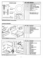
1
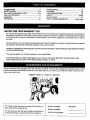
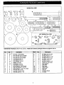
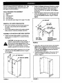
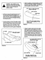
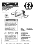
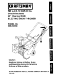
OWNERS MANUAL
CRflFTSMRN
°
5 H.P.
MOW-N-VAC
Model No. 486.24505
CAUTION:
• Before using this product,
read this manual and follow
all Safety Rules and
Operating Instructions.
Sears, Roebuck and Co., Hoffman Estates, IL 60179 U.S.A.
PRINTED
IN U.S.A.
•
•
•
•
•
Safety
Assembly
Operation
Maintenance
Parts
ACCESSORIES
.........................................................
2
SAFETY RULES ....................................................
3,4
FULL SIZE HARDWARE CHART ......................... 5,6
CARTON CONTENTS ..............................................
6
ASSEMBLY ................ _.......... !,.....!.._. .............. _........ 7
OPERATION ........................................................
;.. 18
MAINTENANCE ......................................................
19
STORAGE ...............................................................
20
TROUBLESHOOTING
............................................
20
PARTS ................................................................
23-25
SLOPE GUIDE ........................................................
27
PARTS ORDERING/SERVICE
................. Back Page
LIMITED ONEYEAR WARRANTY: ON
For one year from the date of purchase, when this Mow-N-Vac is maintained and lubricated according to the operating and
maintenance instructions in the owner's manual, Sears will repair any defect in material or workmanship free of charge.
If this Mow-N-Vac is used for commercial or rental purposes_ this warranty applies for only 90 days from the date of
purchase.
This warranty does not cover repairs necessary because of operator negligence or abuse, including the failure to maintain
the equipment according to instructions contained in the owner's manual.
WARRANTY SERVICE IS AVAILABLE BY CONTACTING THE NEAREST SEARS SERVICE CENTER/DEPARTMENT
IN THE UNITED STATES.
This warranty applies only while this product is in the United States.
This warranty gives you specific legal rights, and you may also have other rights which vary from state to state.
Sears, Roebuck and Co. D/817 WA. Hoffman Estates, Chicago, IL 60179
These accessories were available when the unit was purchased. They are also available at most Sears retail outlets
and service centers, Most Sears stores can order repair parts for you when you provide the model numbers of your
tractor and Mow-N-Vac.
REMOTE
HOSE KIT - Model No. 486.24508
|
The model number and serial numbers will be found on a
decal attached to the Mow-N-Vac.
MODEL NUMBER:
SERIAL NUMBER:
You should record bnth the serial number and the date of
purchase and keep in a safe place for future reference.
DATE OF PURCHASE:
486.24505
Any power equ pment car_ cause injury if Operated improper y or f the user does not understand how to operate
the equipment. Exercise caution at all times, when using power equipment.
•
Read and follow all instructions in this operating and
service instruction manual carefully. Be thoroughly
familiar with the controls and proper use of this power
vacuum. Failure to comply with the instructions in this
manual may result in personal injury.
•
Check all bolts for tightness at frequent intervals to help
insure safe operation.
•
Check vinyl hard top boot frequently for wear. Replace if
worn or damaged.
•
Never operate Mow-N-Vac unless deck adapter, hose,
hose adapter (nozzle), elbow, boot and top cover are
properly attached in their place.
•
Do not remove top cover or attempt to empty contents of
cart while engine is running.
•
Keep hands, feet, face, long hair and clothing out of
Mow-N-Vac inlet and discharge areas. There are
ROTATING BLADES inside these openings.
•
Read the vehicle owners manual and vehicle safe
operation rules before using this equipment.
•
Never allow children under 16 to operate this Mow-NVac. Children 16 years and older should only operate
under close parental supervision.
•
Do not allow anyone to operate this equipment without
proper instructions.
•
Do not allow passengers to ride on this equipment or on
the towing vehicle-.
•
:
Never attempt to change hose adapter (nozzle) or to
install remote hose attachment when engine is running.
•
Keep the area of operation clear of all persons, particularly small children. Also keep area clear of pets,
•
Keep shields and guards (e.g. hose adapter [nozzle] and
elbow) in place and securely attached.
•
Check fuel before starting engine. Do not fill fuel tank
indoors, or when engine is running, or while engine is
hot. Wipe off any spilled fuel before starting engine.
•
Always wear safety glasses or other suitable eye
protection when operating or maintaining this equipment.
•
Do not stand behind cart in exhaust discharge area while
engine is running.
•
Do not operate this equipment while intoxicated or while
taking drugs or medication that impairs the senses and
reactions.
Do not change engine governor settings.
•
Do not operate engine if air cleaner or cover is removed,
except for adjustment. Removal of these parts could
create a fire hazard.
When using this equipment, start with the vehicle
transmission in first (low) gear and then gradually
increase speed only as conditions permit.
•
Operate this equipment at reduced speed on rough
terrain, along creeks and ditches and on slopes to
prevent tipping or loss of control. Do not drive too close
to a creek or ditch.
Engine and muffler get hot. Do not touch! To avoid fire
hazard, keep clean of debris and other accumulations,
Never store Mow-N-Vac with fuel in tank. Allow engine to
cool before storing in any enclosure,
Before cleaning, repairing or inspecting, make certain all
moving parts come to a complete stop. Disconnect spark
plug wire and keep wire away from plug to prevent
accidental starting. Keep throttle control lever in stop
position.
Vehicle braking and stability are affected by the addition
of this equipment. Do not fill the Mow-N-Vac to its full
capacity without checking the capability of the towing
vehicle to safely pull and stop with the Mow-N-Vac
attached.
If the Mow-N-Vac should become blocked with debris at
any point, shut engine off and wait until the impeller
comes to a complete stop before attempting to remove
the obstruction. Disconnect spark plug wire to prevent
accidental starting.
Before operating on any grade (hill) refer to the safety
rules in the vehicle owner's manual concerning safe
operation on slopes. Also refer to the SLOPE GUIDE_n
page 27 of this owner's manual. Do not operate on
slopes in excess of 10 degrees. STAY OFF STEEP
SLOPES.
If you strike a foreign object, or if your Mow-N-Vac
should start to vibrate abnormally, stop the engine
immediately, disconnect the spark plug wire and move
the wire away from the spark plug. Allow the machine to
stop and take the following steps.
•
a. Inspect for damage.
b. Repair or replace any damaged parts.
c. Check for loose parts and tighten to assure
continued safe operation.
,_
Follow the maintenance
manual.
Look for this symbol to point out important safety precautions,
Become alert!! Your safety is involved.
instructions as outlined in this
it mean--Attentlont!
This Mow-N-Vae was built to be operated according to the rulea for safe operation In this
DANGER:
operator
canwith
result
serious
Injury.
This unit is
capable of amputating
hands
manual. As
anyIntype
of power
equipment,
carelessness
or error on fingers
the partand
of the
and throwing objects Fa ure to observe the following safety Instructions could result In
serious injury or death.
3
DO NOT REMOVE TOP COVER OR ATTEMPTTO
EMPTY CONTENTS OF CART WHILE ENGINE IS
RUNNING.
DO NOT STAND IN FRONT OF EXHAUST DISCHARGE
AREA WHILE ENGINE IS RUNNING,
EYE PROTECTION SHOULD BE WORN WHEN
OPERATING VACUUM.
DO NOT REMOVE NOZZLE
OR HOSE WHILE ENGINE IS
RUNNING
!
MUFFLER & ADJACENT
MAY EXCEED 150 ° F
AREAS
WARNING
This unit is equipped with an internal combustion engine and should not be used on or near unimproved forest-covered, or
grass-covered land unless the engine's exhaust system is equipped with a spark arrester meeting applicable Local or state
laws (if any). If a spark arrester is used, it should be maintained in effective working order by the operator.
In the State of Califomia the above is required by law (Section 4442 of the California Public Resources Code). Other
states may have similar laws. Federal laws apply on federal lands. A spark arrester muffler is available at you nearest
engine authorized service center.
This unit is shipped WITHOUT GASOLINE or OIL.. After assembly, see Separate engine manual for proper fuel and
engine oil recommendations.
SHOWNFULLSIZE
HARDWARE
Ref.
A
B
C
D
E
F
G
H
I
J
K
L
M
N
0
P
Qty.
38
2
9
1
9
1
36
1
28
1
2
3
2
3
4
2
PACKAGE
(Mow-N-Vac Carton) Additional hardware packages shown on pages 6 and 14.
Description
Ref.
Hex Nuts, 1/4.20 Thread
Hex Lock Nuts, 5/16-18 Thread
Hex Lock Nuts, 3/8-16 Thread
Hex Lock Nut, 1/2-13 Thread
Lock Washers 3/8" I.D.
Lock Washer, 5/16" I.D.
Lock Washers, 1/4" I.D.
Washer, 7/16" Std.
Flat Washers 1/4" I.D.
Flat Washer, 5/16" Std.
Nylon Washers, 21/64" (Small)
Steel Flat Washers 1-1/2" O.D.
Nylon Washers, 1-1/2" O.D. (Large)
Hex Bolts, 3/8" x 3-1/4"
Hex Bolts, 1/4-20 x 2-3/4"
Hex Bolts, 3/8-16 x 1-1/4"
Q
R
S
T
U
V
W
X
Y
Z
AA
BB
CC
DD
EE
FF
5
Qty.
5
4
5
1
28
2
2
5
2
1
1
1
2
1
2
1
Description
Hex Bolts, 5/16-18 x 3/4"
Hex Bolt, 3/8-16 x 1.0"
Hex Bolts, 3/8-16 x 1-1/2"
Hex Bolt, 1/2-13 x 1-1/4"
Hex Bolts, 1/4-20 x 3/4"
Hex Bolt, 1/4-20 x 1"
Hex Bolt, 1/4-20 x 1-1/4"
Clamps, for Cart Panels
Door Supports
Hitch Plate
Stop Angle
Hairpin Cotter
Door Latch
Hitch Pin
Tie Straps (Short)
Tie Strap
_t_, • ,_,f
,_
_ Description'
•SHOWN FULI;;SI;[IE _
A
B
C
D
E
F
G
H
I
.IB
,_._.
e
14
25
2
27
14
4
2
2
2
Sit. TrussHd. Bolt,5/16" x 3/4" Lg.
Hex Bolt,1/4" x 1/2"
Hox Bolt,1/4" x 1-3/4"
Hex Nut, 1/4-20 Thread (SEMS)
Hex Nut,5/16-18 Thread (SEMS)
FlatWasher, 1"
CotterPin, 1/8"x 1-1/2' Lg.
HubCap
SpacerTube, 2" Lg.
Bag contains extra 1/4" x
1/2" bolts and 1/4" nuts
Not Shown Full Size
H
G
I
HARDWARE PACKAGE
CARTON
(Cart Body Carton)
CONTENTS
Ref.
CARTON CONTENTS
13
(_ARTON CONTENTS
Description
1
2
3
4
5
6
7
8
9
2
1
1
1
1
1
1
2
2
Ref.
Qty.
1
2
3
4
5
6
7
8
9
10
11
12
13
14
15
16
1
2
1
1
Front Panel
Side Panels (Left & Right)
Rear Door
Hose
2
1
1
1
1
1
1
1
1
1
1
1
Hose Clamps
Cross Brace
Hose Hanger Assembly
Hitch Bracket
Elbow
Hose Adapter (Nozzle)
Adapter Bracket
Deck Adapter
Poly Hard Top
Engine Base Assemb|y
Tongue, Rear Section
Tongue, Front Section
Corner Cap
Latoh Lock Assembly
Latch Stand Bracket
Tailgate Reinforcement Bracket
Front Panel
Wheel Support
Axle
Cart Body
Wheel
(Cart Body Carton)
_/9
_
Qty.
14\_
(Mow-N-Vac
_0
15_
_/1
i_
Carton)
6
Description
•
This unit is shipped WITHOUT GASOLINE or OIL. -After
assembly, see separate engine manual for proper fuel
and engine oil recommendations.
Position the tailgate reinforcement bracket on outside
of cart as shown in figure 2. Fasten to the bottom of
the cart body using six 5/16" x 3/4" slotted head
screws and 5/16" hex nuts (SEMS). Do not tighten.
See figure 2.
Fasten the tailgate reinforcement bracket to the sides
of the cart body using four 1/4" x 1/2" hex bolts and
1/4" hex nuts (SEMS) as shown in figure 2. Do not
tighten.
TOOLS REQUIRED FOR ASSEMBLY
•
(1)
(1)
(2)
(2)
(2)
Screwdriver
Pliers
7/16" Wrenches
1/2" Wrench
9/16" Wrenches
(2)
3/4" Wrenches (only if figure 24 on page 14 is used)
REMOVAL
•
OF PARTS
1/4" HEX NUT
FROM CARTON
_.J
Remove the hardware pack and all loose parts from
the Carton. Be sure the carton is empty before :
discarding.
Lay out all the parts as shown in the carton contents.
Keep contents of hardware packages separated.
•
ASSEMBLY
•
OF PARTS
&
_;:;__'"I-"_
._
5/16 X 3/4"
SLOTTED BOLT
BODY CARTON
Position cart body halves upright on a smooth level
surface such as a garage floor or a paved driveway.
See figure 1.
CAUTION:
•
IN CART
_'"
114" x 1/2"
5/16" HEX
NUT (SEMS)
Do not leave the cart unat-
tended in upright position during assembly. A
falling cart can cause personal injury! Pay
close attention to the stability of the cart while
it remains in an upright position. For best
stability, assemble on a smooth level surface.
TAILGATE
REINFORCEMENT
BRACKET
FIGURE 2
•
Assemble halves together using three 1/4" x 1/2" hex
bolts and 1/4" hex nuts (SEMS) as shown in figure 1.
Do not tighten.
•
1/4" x 1/2" HEX BOLT
At this fime, with the cart body halves pulled together,
tighten the six slotted head screws assembled in
figure 2 and then tighten the four hex bolts assembled
in figure 2, Do not tighten the three hex bolts that
were assembled in figure 1.
Carefully reverse the position of the cart so that it
rests on the tailgate reinforcement bracket, as
shown in figure 3.
1/4" HEX NUT (SEMS)
FIGURE 3
FIGURE 1
7
•
Autimble the front p_mel over the end of the cart
using six 1/4" x 1/2' hex bolts and 1/4" hex nuts
(SEMS) as shown in figure 4. Leave two holes open
in the bottom of the panel as shown in figure 4. With
the cart body halves pulled together, tighten the four
bolts In the bottom of the front panel, then tighten the
boltln each side.
•
Assefnble the latch stand braCKet to tne cart uslng
four I/4' x I/2" hex bolts and I/4" hex nuts (SEMS).
TIGHTEN. See figure 6.
LATCH STANDBRACKET
1/4" x 1/2'
HEX BOLT
At this time tighten the three bolts on the bottom of
the cart which were assembled in figure 1.
LEAVE HOLES OPEN FOR
LATCH STAND BRACKET
1/4" x 1/2"
HEX BOLTS
1/4" HEX NUT (SEMS)
114" HEX
NUT (SEMS)
/
FIGURE6
I
/
To prevent accidental tipping during the following
assembly procedures, lower the cart to rest upside
down on the top flanges, so that the wheel support is
facing up. Refer to figure 10 on page 9.
1/4" HEX
NUT (SEMS)
FIGURE 4
Assemble the wheel support to the bottom of the cart
using eight 5/16" x 3/4" slotted head screws and
5/16" hex nuts (SEMS) as shown in figure 5. Heads of
screws go to the inside of cart. Tighten.
ASSEMBLY
•
SLO'I-rED SCREW
5/16" x 3/4"
WHEEL
SUPPORT
l
OF PARTS
IN MOW-N-VAC
Assemble the front tongue over the top of the rear
•tongue using three 3/8" x 3-1/4" hex bolts, 3/8" lock
washers and 3/8" hex lock nuts. See figure 7.
TONGUE
(REAR)
_j.13/8"
X 3-1/4" HEX BOLT
_
TONGUE
\
NUT(SEMS
3/8" LOCK
WASHER
FIGUI_E 5
FIGURE 7
8
CARTON
_
3/8" HEX
LOCK NUT
•
Assemble the hitch bracket to the drawbar tongue,
using two 3/8" x 1-1/4" hex bolts, 3/8" lock washers
and 3/8" hax nuts. Tighten. See figure 8.
Positibn the tongue 0_ _e bottom of the cart as
shown in figure 10. Assemble the axle through the
wheel supportand the tongue. Fasten the axle to
the wheel support using two 1/4" x 1-3/4" hex bolts
and 1/4" hex nuts (SEMS). Tighten.
3/8" x 1-1/4"
HEX BOLT
_
3/8" LOC K'_(__F--_
WASHER
_
HITCH BRACKET
]lJ_
IMPORTANT:
Make sure the tongue is securely locked
to the latch stand bracket by the latch lock assembly.
TONGUE
1/4" x 1-3/4"
HEX BOLT
..,..I AXLE
/_
_ , _
3/8" HEX._,,._
LOCK NUT
TONGUE
(DRAW BAR)
FIGURE 8
•
•
Assemble the latch lock assembly to the tongue using
two 1/4" x 2-3/4" hex bolts, two 1/4" lock washers and
two 1/4" hex nuts. Fasten to the two front holes in the
forward grouping of four holes as shown in figure 9.
Assemble the angle stop to the tongue using two 1/4"
x 2-3/4" hex bolts, two 1/4" lock washers and two 1/4"
hex nuts. Fasten to the two front holes in the rear
grouping of four holes as shown in figure 9.
/1
"(
) /
FIGURE 10
114-20 x 2-3/4" HEX BOLT
ANGLE
_,'
LATCH LOCK
ASS'Y.
TONGUE
Assemble a spacer tube onto each end of the axle as
shown in figure 11.
Assemble a fiat washer, a wheel (valve stem facing
out), and another flat washer onto the axle as
shown in figure 11. Secure the wheel with a cotter
pin, spreading the ends so that a hub cap can fit
over the pin. Assemble the hub cap by pressing it
onto the flat washer. Repeat on other end of axle.
SPACER TUBE
1/4" LOCK
WASHER
WHEEL
1/4" HEX
NUT
AXLE
FLAT
WASHER
FIGURE 9
FLAT
WASHER
.
HUB CAP
FIGURE
_11
co'rrER
PIN
Turd the cert right side up to rests on its wheels.
•
Placea comer cap over each front comer of the cart
as shown in figure 13.
Place the engine assembly (blower housing to the
front) onto the welded angles of the tongue, aligning
the holes in the engine base with the holes in the
welded angles. See figure 12.
•
CORNER CAPS
Secure the engine base assembly to the welded
angles using four 3/8" x 1" hex bolts, 3/8" Iockwashers and 3/8" hex lock nuts. See figure 12. 13ghten all
nuts and bolts securely.
NOTE: Make sure engine is positioned with blower
housing to the front.
FIGURE 13
Position a side panel on top of the cart bed flange and
front corner cap. Align holes in side panel with holes
in comer cap and holes in top of cart bed flange.
Fasten together using two 1/4" x 3/4" hex bolts, two
1/4" fiat washers, two 1/4" lock washers and two 1/4"
hex nuts. Repeat for other side. See figure 14.
ENGINE
BASE
ASSEMBLY
SIDE PANELS
3/8-16 x 1"
HEX BOL
m=,_=
"_
FRONT
3/8" HEX NUT
WELDED ANGLES
ON TONGUE
3/8" LOCK
WASHER
LOCK
WASHER
FIGURE 12
1/4" HEX NUT
FIGURE 14
10
•
Assemble front panel over the ends of the side panels
and on top of the cart bed flange and the comer caps.
Leaving the top holes in the front panel empty, fasten
it to the cart body and the side panels using six 1/4"
x 3/4 =hex bolts, six 1/4" flat washers, six 1/4" lock
washers and six 1/4" hex nuts. See figure 15.
1/4" LOCK
WASHER
1/4" FLAT
WASHER
Install the poly hard tbp over the front and side
panels. Fasten it to the panels using fourteen 1/4" x
3/4' hex bolts, 1/4' fiat washem, 1/4' lock washers
and 1/4" hex nuts. Seefigure 17.
Assemble four clamps onto the cart flanges, two on
each side of the cart, positioned approximately 12"
from each end. Fasten each clamp from the bottom
with a 3/8" x 1-1/2" hex bolt. See figure 17.
1/4" x 3/4"
HEX BOLT
Assemble a clamp at center of front panel and cart
flange using a 3/8" x 1-1/2" hex bolt. See figure 17.
\
1/4" LOCK
WASHER
1/4" HEX NUT
POLY HARD TOP
FRONT
PANEL
FIGURE 15
CLAMP
Assemble the cross brace to the two top holes at the
rear of each side panel using four 1/4" x 3/4" hex
bolts, four 1/4" lock washers and four 1/4" hex nuts.
See figure 16.
CROSS
BRACE
CLAMP
CENTER
FRONT
1/4" x 3/4"
HEX BOLT
FIGURE 17
1/4"
FIGURE 16
11
• .Assemble ==door latch at each end of crom brace
using a 5/16" x 3/4" hex bolt, a nylon washer and a
5/16" hex lock nut. Place nylon washer between door
latch and cross brace, Tighten so that latch is snug
but will still rotate, See figure 18.
DOOR
LATCH
• -Assemble door support brackets undemeath the rear
of the cart bed by removing the hex nuts from the
bolts shown in figure 18, Fasten the brackets to the
cart using the same hex nuts which were removed.
5/16" HEX
LOCK NUT
NYLON
WASHER
TIE
CROSS
BRACE
(SHORT
1/4" x 1"
HEX BOLT
I/4" FLAT
WASHER
1/4"
HEX NUT
I/4" LOCK-WASHER
FIGURE 19
'5/16" x 3/4"
HEX BOLT
BOLT
DOOR
SUPPORT
BRACKET
Assemble the elbow to the blower housing, using two
5/16 =x 3/4" hex bolts, two large 1-1/2" nylon washers,
and two 1-1/2" flat steel washers. See figure 20.
Tighten hex bolts securely,
i
4-----
HEX NUT
FIGURE 18
1-1_"O.D.
NYLON
WASHER
Assemble one short tie strap to each side of rear door
using one 1/4" x 1-1/4" hex bolt, two 1/4" fiat washers,
one 1/4" lock washer and one 1/4" hex nut, Assemble
an "S" hook through the loose end of each strap. See
figure 19.
ELBOW
Assemble a 1/4" x 1• hex bolt with a 1/4" hex nut to
outside of hole on each side of cart bed and secure
from inside with a 1/4" lock washer and a 1/4" hex
nut. See inset in figure 19.
5/16" x 3/4"
HEX BOLT
Assemble door to rear of cart by resting bottom of
door on door support brackets and rotating top of door
forward to meet cross brace, Latch top of door on
each side. See figure 19.
BLOWER
HOUSING
Hook both the tie straps onto the 1/4" x 1" hex bolts
which were just assembled. See figure 19.
FIGURE 20
12
Assemble the hose adapter (nozzle) intoslots on
,
front of housing and secure to housing with a 5/16" x ....
3/4" hex bolt, a 5/16" lock washer and a 5/16" fiat
washer as shown in figure 21. Remove hex nut and
lock washer from weld bolt and place a 1-1/2" O.D.
flat washer onto weld bolt so that it overlaps the hose
adapter as shown in figure 21. Fasten with original
hex nut and lock washer. Tighten securely.
o; Assemble a hose damp on end of hose and push
hose onto the hose adapter (nozzle). seeflgure 22.
Secure hose by tightening the screw on hose clamp.
Do not collapse hose adapter when tightening.
1-1/2* O.D. FLAT WASHER
MUST OVERLAP ON HOSE
ADAPTER (NOZZLE)
HOSE
ADAPTER
HOSE
5/16" LOCK
WASHER
HOSE CLAMP
FIGURE 22
Place hose hanger assembly into welded tube on
blower housing assembly. See figure 23.
Wrap the rubber tie strap under the hose and fasten
the hooks to the end of the hose hanger assembly.
See figure 23.
5/16" x 3/4"
HEX BOLT
SLOT IN HOUSING
HOSE ADAPTER
(NOZZLE)
FIGURE 21
HOSE
ASS'Y.
_' RUBBER
TiE
STRAP
FIGURE 23
z
13
ASSEMBLYOF THE DECK ADAPTER
(#62468) TO THE TRACTOR AND MOWER
•
A hitch plats is furnished lot;tractors having square
(straight) hitch frames;to prevent binding of the MowN-Veo hitch In tight turns. Assemble as shown in "
figure 24. Tapered hitch frames, as shown with dotted
lines in figure 24, generally do not require the added
hitchpleta.
NOTE: Tractors with light (thin) metal frames may
require the added hitch plate to avoid excessive wear.
1/2" x 1-1/4"
HEX BOLT
TRACTOR
HITCH FRAME
Contents of Hardware Pack for Deck Adapter:
See Figure 2S
HITCH
_LJJ._. PIN
1
(SQUARE)
HITCH
PLATE
HAIRPIN
j/,
7/16" STD. W
WASHER
1/2" LOCK NUT
TRACTOR HITCH _"
FRAME (TAPERED)
COTTER
__,
_
:
',
.,
'
.""
Key
Qty.
A
B
C
D
E
F
G
H
I
J
K
2
3
2
3
3
3
12
3
1
1
1
Deecdptlon
Hex Bolts, 5116"x 1"
Hex Bolts, I/4" x 3/4"
Carriage Bolts, 5116"x 314"
Hex Lock Nuts, 5/16-18 Thread
Hex Lock Nuts, 1/4-20 Thread
Flat Steel Washers, 1/4' Std.
Flat Washers, 5/16" Std.
Nylon Washers, 21/64
Mounting Strap
Angle Bracket
Mounting Bracket
".
"""
FIGURE 24
•
You are now readyto assemble the deck adapter to
the mower deck.
NO;r SHOWN FULL SIZE
FIGURE 25- FULL SIZE
NOTE: Not all of the hardware will be used for any one
particular fit up.
•
Remove the mower discharge deflector from your
mower deck. Save the deflector and hardware for
remounting.
IF YOU HAVE A MURRAY TRACTOR WITH A 38" OR
40" DECK, SKIP DIRECTLY TO PAGE 16.
IF YOU HAVE A MURRAY TRACTOR WITH A 46"
DECK, SKIP DIRECTLY TO PAGE 17.
14
"_
CAUTION:
Mower defl_0r
Position the adapter over the deck opening, and check
for fit of cutout as shown in figure 27. Trim cutout, if
necessary, to allow tilting of adapter, keeping the fit as
close as possible for best vacuum suction.
must be
isepremoved,
Do Mow-N-Vac
Not operate deck
mower
unless
aced when
adapter
adapter or deflector is in place and
properly mounted.
A
NOTE: Make sure adapter clears gauge
wheels on mower deck
DECK ADAPTER
o
Identify your mower deck (see fold outs) and cut out
the correct discharge opening template for your
mower deck size. If there is no template for your deck
size you can make your own template by marking
around a piece of cardboard held against the edge of
the discharge opening.
_=
Curl on deck may be located outside of
adapter or Inside depending on deck
opening design
Tape the template to the face of the adapter, locating
template approximately 1/2" from front and 1/4" down
from top of adapter. Keep as close to top as possible.
See figure 26. Mark outline of template on face of
adapter using white crayon, nail or scriber. Drill a
starting hole inside the outline, then use a saber saw
or key hole saw to cut out the opening. See figure 26.
FIGURE 27
o
1/4" DOWN
IMPORTANT:
Keep cut-off as close to
the top edge as posslble.
Holding the adapter bracket and the deck adapter
together, position the deck adapter on the mower
deck. Keeping the edge of deck adapter as close as
possible to the offset in the adapter bracket, see if the
slot in the adapter bracket can be aligned with one or
two of the deflector holes in your mower deck's
discharge opening. If the bracket can not be located
correctly using existing holes, it will be necessary to
drill one or two 5/16" diameter holes in the deck. See
figure 28.
Use existing holes or drill 5/16"
diameter hole or holes.
ADAPTER BRACKET
1/2" FROM FRONT
FIGURE 26
DECKADAPTER
MOWER DECK
Keep edge of adapter as close
as possible to offset in bracket
FIGURE 28
15
.
•
FOR 1990 AND NEWER MURRAY
TRACTORS WITH A 38" OR 40" DECK
Assemble the a_dapterbracket to the deck using two
5/16" x 1' hex bolts, 5/16" flat washers and 5/16" lock
nuts. See figure 29.
NOTE: It may be necessary to use extra 5/16" fiat
washers to shim under the bracket next to the deck
surface. Ten extra washers have been furnished as
shims. -See figure 29.
,"_f(2)
,I
Cut out two templates and place on deck adapter as
shown in figure 31. Tape smaller one on top and
larger one on the side and bottom. After they are in
place, carefully mark around the templates, then cut
out adapter to obtain correct opening.
Bolt end of mounting strap to the 5/16" bolt on the
mower deck. The other end of the strap will bolt to a
hole in the deck adapter, which must be ddlled.
Position the adapter on the deck, then drill a 5/16"
hole in the bottom of the adapter that will align with
the hole in the strap. Fasten the adapter to the strap
using a 1/4" x 3/4" hex bolt, 1/4" flat washer, nylon
washer and 1/4" hex nut. See figure 31.
5/16" LOCK NUTS
(_
..,---- 12)5/16" FLAT
_
_
WASHERS
ADAPTER BRACKET
5/16" x 1" HEX BOLT j*'(_
5/16" flat washers
used as needed for
shims to adjust for
variations in decks.
38"/40" TEMPLATE
TEMPLATE TO CUT OUT SLOT
OF DECK ADAPTER
_J
FIGURE 29
CUT
OUT xSLOT
TOP
1/4"
3/4"INHEX
BOLT
1/4" FLAT WASHER
With deck adapter positioned correctly over the
discharge opening, use the adapter bracket as a
template and ddll three 9/32" diameter holes in the top
of the deck adapter. See figure 30.
Bolt deck adapter to bracket using three 1/4" x 3/4"
bolts, nylon washers, 1/4" fiat washers and 1/4" lock
nuts. Nylon washers should be against the inside of
the deck adapter. See figure 30.
WASHER
BOLTTHIS
END OF
STRAP TO 5/I 6" BOLT
ON MOWER DECK
MOUNTING STRAP
1/4" LOCK NUT
DECK ADAPTER
(3) 1/4" HEX
LOCK NUTS
FIGURE 31
ADAPTER
(3) NYLON
WASHERS
Assemble end of hose and hose clamp over the round
opening of deck adapter and tighten clamp. GO
DIRECTLY TO THE OPERATION INSTRUCTIONS
WHICH ARE LOCATED ON PAGE 18.
MOWER DECK
(3) 1/4" STEEL WASHERS
(3) 1/4" x 3/4" HEX BOLTS
FIGURE 30
Assemble end of hose and a hose clamp over the
round opening of deck adapter and tighten clamp.
GO DIRECTLY TO THE OPERATION INSTRUCTIONS ON PAGE 18.
16
FOi:i 990 AND NEWER MURRAY
TRACTORSWITH
A 46" DECK
Tape 46" template onto deck adapter, Mark and then
cut out adapter,
Fasten the angle bracket and the mounting bracket to
the mower deck as shown in figure 32. Use two 5/16"
x 3/4" carriage bolts, 5/16" flat washers and 5/16".
lock nuts. The bolt heads go on inside of mower
deck,
Drill two 5/16" diameter holes in the deck adapter that
will align with the holes in the angle bracket and the
mounting bracket. Assemble the deck adapter to both
brackets using two 1/4" x 3/4" hex bolts, 1/4" fiat "
washers, nylon washers and 1/4" lock nuts. Se_ figure 32.
\
ANGLE BRACKET
NYLON WASHER
1/4" FLAT
\.
,1/4',
XXX_
1/4" x 314"
\
NYLON WASHER.
114" x 3/4" HEX BOLl
FIGURE 32
Assemble end of hose and hose clamp over the round
opening of deck adapter and tighten clamp. GO
DIRECTLY TO THE OPERATION INSTRUCTIONS
WHICH ARE LOCATED ON PAGE 18.
17
HOW TO USE YOUR MOW-N-VAC
Read this owner's manual and safety rules before
operating your Mow-N-Vac.
BEFORE
•
•
•
&
STARTING
Your Mow-N-Vac _ngine is shipped without oil or
gasoline. Service the Mow-N-Vac engine with oil and
gas as instructed in the separate engine manual.
Inspect the Mow-N-Vac to make sure all covers (rear
door, hard top boot, elbow, hose adapter, hose and
deck adapter are properly attached.
Check tires for proper inflation (12 - 14 Ibs).
•
Before beginning operation, inspect the Mow-N-Vac
to make sure all covers (rear door, hard top boot,
elbow, hose adapter, hose and deck adapter) are
properly attached.
Begin operation at low speed, adjusting forward
speed to match grass height and/or moisture condition to prevent clogging.
•
with the engine running, or while the engine
WARNING:
Never fill fuel tank indoors, or
is hot. Do mot smoke while filling tank.
HOW
•
•
TO STOP
YOUR
&
MOW-N-VAC
To stop engine, move the throttle control lever to the
OFF position.
Disconnect spark plug wire from plug to prevent
accidental starting while equipment is unattended or
is being worked on.
areas
are hot!
CAUTION:
The muffler and adjacent
YOUR
To empty cart, shut off tractor engine and set
brake.
Shut off Mow-N-Vac engine.
Remove rear door from cart.
Release the latch holding cart down to the tongue by
pulling up on the latch lever. See figure 33.
•
•
•
MOW-N-VAC
sure that no one is near the cart before
CAUTION: To avoid possible injury, be
releasing the latch.
without all covers being properly attached
WARNING:
Never start or run the engine
to the blower housing and cart.
•"
•
•
•
•
•
•
•
WARNING:
Should your Mow-N-Vac
become clogged, shut off tractor and
Mow-N-Vac engine. Before attempting to
unclog, remove wire from spark plug to
prevent accidental starting.
rocks
with theNever
mower
blades
CAUTION:
drive
over engaged
gravel or
and running.
•
HOW TO START
CAUTION: -Vehicle braking and stability
may be affected with the addition of an
accessory or an attachment, Be aware of
changing conditions on slopes.
Check oil and gas in Mow-N-Vac engine.
Attach spark plug wire to spark plug.
Move choke lever on engine to CHOKE position.
(A warm engine may not require choking.)
Move throttle control lever on engine to FAST position.
•
Using a rake or suitable tool, pull the grass clippings
and/or leaves out of cart.
After cart is emptied, tip cart forward and secure to
tongue with latch. Reattach the rear door and the
hard top boot.
Grasp starter handle and pull rope out slowly until
engine reaches start of compression cycle (rope will
pull slightly harder at this point). Let the rope rewind
slowly.
Pull rope with a rapid, continuous, full arm stroke.
Keep a firm grip on starter handle. Let rope rewind
slowly. Do not let starter handle snap back against
starter.
Repeat instructions in two preceding paragraphs until
engine fires. When engine starts, move choke control
gradually to RUN position.
FIGURE 33
18
CUSTOMER
•
RESPONSIBILITIES
Read and follow the maintenance schedule and the maintenance procedureslisted in this section.
M
A,NTENANCESCHEOOLE
Fill in dates as you
completeregularservice.
_°_
e_,_e_
ServiceDates
F
Checkfor loosefasteners
X
Checksoftvinylboot
X
Checktire pressure
X
Checkeneineoil level
X
Lubricate
X
Clean
X
X
Maintainermineper instructions
belowand in enoinemanual.
BEFOREEACH
USE
:
A
CHECK FOR LOOSE FASTENERS
• Make a thorough visual check of the snow thrower
for any bolts and nuts which may have loosened.
Retighten any loose bolts and nuts.
CHECK SOFT VINYL BOOT
•
ENGINE
Check the soft vinyl boot (on front of hard top) for
wear. Replace if worn or damaged.
•
CHECK TIRE PRESSURE
•
Check tire pressure regularly. Recommended tire
pressure is 12-14 Lbs.
CHECK ENGINE OIL LEVEL
• Check oil level before each use. Maintain engine oil
as instructed in the separate engine manual.
•
WARNING: Always stop engine and
disconnect spark plug wire before cleaning, lubricating or before performing any
repairs or maintenance.
MAINTENANCE
Service sir cleaner every 25 hours under normal
conditions. Clean every few hours under extremely
dusty conditions. Poor engine performance and
flooding usually indicates that the air cleaner should
be serviced. To service the air cleaner, refer to the
separate engine manual.
The spark plug should be cleaned and the gap reset
once a season. Spark plug replacement is recommended at the start of each season. Check the
engine manual for correct plug type and gap specifications.
LUBRICATION
•
•
At the beginning of each season, lubricate the latch,
latch pivot bolt, and the axle where the hitch tongue
pivots, with a light machine oil.
At least once a season, grease or oil the wheel
bearings. Use automotive wheel bearing type grease
or 20 weight oil.
CLEANING
•
•
Make sure the cart, the side and front panels and top
are cleaned after each use. Grass clippings and
leaves left in the cart will mildew and cause damage if
not cleaned out.
Clean the engine regularly with a cloth or brush.
Keep the cooling fins on the engine housing clean to
permit proper air circulation which is essential to:
• engine performance and lifo. Be sure to remove all
. dirt and debrisfrom muffler area.
19
•
•
Clean the engine and the entire unit thoroughly.
Refer to engine manual for correct engine storage
instructions.
•
If storing in an unventilated or metal storage shed,
coat metal parts with light oil or silicone to prevent
rust.
Store unit in a clean, dry area.
•
PROBLEM
POSSIBLE CAUSE(S)
CORRECTIVE ACTION
Engine fails to start
1. Spark plug wire disconnected.
2. Fuel tank empty, or stale fuel.
3. Fuel shut-off valve closed
1. Connect wire to spark plug.
3. Fill tank with clean, fresh fuel.
4. Open fuel shut-off valve.
(if so equipped).
4. Faulty spark plug.
5. Clean, adjust gap or replace.
Loss of power;
operation erratic.
1. Connect and tighten spl,rk plug wire.
2. Move choke lever to OFF position.
3. Clean fuel line; filltank with clean
fresh gasoline.
4. Disconnect fuel line at carburetor to drain
fuel tank. Refill with fresh fuel.
1. Spark plug wire loose
2. Unit running on CHOKE.
3. Blocked fuel line or stale fuel.
4. Water or dirt in fuel system.
Engine overheats
Too much vibration
Unit does not
discharge
5. Carburetor out of adjustment.
6. Dirty air cleaner.
5. Adjust carburetor.*
6. Service air cleaner.*
1. Carburetor not adjusted
properly.
2. Engine oil level low.
1. Adjust carburetor.*
2. Fill crankcase with proper oil.
Stop engine immediately and disconnect
spark plug wire. Tighten all bolts and nuts.
Make all necessary repairs. If vibration
continues, have unit serviced by an
authorized service dealer.
Loose parts or damaged
impeller.
1. Discharge chute (elbow)
clogged.
1. Stop engine immediately and disconnect
spark plug wire. Clean inside of housing
and discharge chute (elbow).
2. Stop engine immediately and disconnect
spark plug wire. Remove lodged object.
3. Stop engine and empty cart.
2. Foreign object lodged in
impeller.
3. Mow-N-Vac cart is full.
*Refer to the engine manual packed with your unit.
NOTE:
For repairs beyond the minor adjustments
dealer.
listed above, please contact your nearest authorized
2O
service
NOTES
21
NOTES
MODEL
486.24505
MOW-N-VAC
CART
BODY
1
2
/
\
/
14
14
io
i
18j?
4
9
I
11
12
\
11
5
6
13
\
:IEFo
NO.
PART
NO.
QTY.
1
2
3
4
5
6
7
8
9
23985
62458
23492
23507
23297
62455
23488
23484
46272
2
1
1
1
1
1
1
2
2
DESCRIPTION
Cart Body
Tailgate Reinforcement
Front Panel
Wheel Support
Latch Stand Bracket
Ass'y, Latch Lock
Axle, Wheel 1" Dia.
Cap, Front Corner
Wheel, 15/6.00 x 8.00
Bracket
REF.
NO.
PART
NO.
QTY.
10
11
12
13
14
15
16
17
18
43093
43601
44678
43014
43175
1509-69
46978
143814
_ 46980
2
4
2
2
25
2
27
14
14
23
DESCRIPTION
Cotter Pin, 1/8" Dia. x 1-1/2"
Washer, Flat 1"
Spacer Tube, 1-1/4" O.D. x 2" Lg.
Hub Cap
Hex Bolt, 1/4-20 x 1/2" *
Hex Bolt, 1/4-20 x 1-3/4" *
Hex Nut, 1/4-20 Thread (SEMS)
Sit. Truss Hd. Bolt, 5/16-18 x 3/4" Lg.*
Hex Nut, 5/16-18 Thread (SEMS)
MODEL
486.24505
MOW-N-VAC
82 (20,31,57,62,63,64,65)
65
/
/
2O
31
57
62
64
20
24
51
41
30
63
80,
3948 47 49
/
14
47
41
21
67
27
3
42
5336 --_
ADAPTER
46..
77
KIT # 62468
81
J
73
ss----_
54"-_
\
\
TO
TRACTOR
39.q
75
24
MODEL 486.24505
REF.
NO.
PART
NO.
QTY. DESCRIPTION
1
2
3
4
5
43063
23655
23475
62450
2
1"
1
1
1
6
7
8
9
10
43085
43086
43064
23474
43749
4
4
6
1
2
11
12
13
14
15
17
18
19
20
21
22
23
24
25
26
27
28
29
30
31
710-0627
43086
62486
681-0075
14563
47048
43003
43080
23842
43086
43083
62451
43788
43791
43792
43793
23834
23835
23833
44791
2
2
1
1
1
1
1
6
4
5
4
1
1
1
1
2
1
1
1
1
32
33
34
36
37
38
39
49
41
43790
43884
23478
23540
43003
43796
43088
43177
43178
1
1
5
1
9
4
31
36
38
MOW-N-VAC
REF.
NO.
Hex Bolt, 5/16" x 1"
Stop Angle
Hitch Bracket (Heavy Duty)
Engine Base Aas'y
5 FI.P. B&S Engine
(135212-1313-E1)
He)( Bolt, 5/16-18 x 1-1/2"
LockWasher 5/16" ID
Hex Lock Nut 5/16-18 Thread
Bracket, Engine To Blower
Hex Thread Cut Bolt,
5/16-18 x 3/4"
Hex Bolt, 5/16-24 x 3/4" LB. Gr. 5
Lock Washer, 5/16" ID
Blower Housing Ass'y
Vane Plate Ass'y
Nozzle Plate Ass'y
Hex Bolt, 3/8-24 x 1-3/4" Grade 5
Lock Washer 3/8" ID
Carriage Bolt, 5/16" x 3/4" LB.
Boot Mounting Strap
Lock Washer 5/16" ID
Hex Nut, 5/16-18 Thread
Hose Hanger Ass'y
Elbow w/Deflector
Hose Adapter (Nozzle)
6" O.D. Hose
Hose Clamp 6" Dia.
Side Panel (R.H.)
Front Panel
Side Panel (L.H.)
Poly Hard Top
(Available only with item no. 81)
Tie Strap 25" LB.
Hitch Pin
Clamp, Cart Ext.
Hitch Plate
Lock Washer 3/8" ID
Hex Bolt, 1/4" x 2-3/4" LB. Grade 5
Flat Washer, 1/4" ID
Lock Washer, 1/4" ID
Hex Nut, 1/4-20 Thread
PART
NO.
42
43
44
45
46
47
48
49
50
51
52
53
54
55
56
57
58
59
60
61
62
43343
1
43087
2
43082
9
43001
4
43064
3
43572
3
43553
2
43182
=5
43081
1
44790
1
43768
5
43351
1
43262
1
43352
1
43012
31
43882
21
1543-69 I 2
23789
2
23836
1
23838
2
23837
1
63
44792
1
64
65
66
67
69
70
71
72
73
74
75
76
77
78
79
80
81
44796
43910
44840
43661
1543-69
63025
63026
46938
43081
43830
23560
23825
23826
23827
43013
1509-90
62468
1
21
2
2
3
1
1
3
12
1
1
1
1
1
3
2
1
82
62836
47502
* Purchase Common Hardware Locally
25
QTY.
DESCRIPTION
Hairpin Cotter, 1/8"
Hex Bolt, 3/8" x 1-1/4;'
Hex Lock Nut, 3/8-16 Thread
Hex Bolt, 3/8" x 1" (Grade 5)
Hex Lock Nut, 5/16-18 Thd.
Flat Washer, 1-1/2" OD
Nylon Washer, 1-1/2" OD
Hex Bolt, 5/16" x 3/4" LB.
Flat Washer, 5/16" Std.
Poly Rear Door
Hex Bolt, 3/8" x 1-1/2" LB.
Hex Bolt, 1/2" x 1-1/4" LB.
Hex Lock Nut, 1/2" Thd.
Flat Washer, 7/16" Std. Wrt.
Flex Bolt, 1/4" x 3/4" LB.
Rivet
21/64" Nylon Washer
Door Latch
Cross Brace
Door Support
Screen Support
(Available only with item no. 81)
Screen
(Available only with item no. 81)
Boot
Washer, 3/16"
Tie Strap
Hex Bolt, 1/4" x 1" LB.
21/64" Nylon Washer
Rear Section Tongue Ass'y
Front Section Tongue Ass'y
Hex Bolt, 3/8" x 3-1/4" LB.
Flat Washer, 5/16" Std.
Deck Adapter
: Bracket, Deck Adapter
Mounting Strap
Angle Bracket
Mounting Bracket
Hex Lock Nut, 1/4" Thd.
Hex Bolt, 1/4-20 x 1-1/4" LB.
Deck Adapter Kit (Includes parts
shown in box on page 24.)
Hardtop assembly (Includes items
20, 31, 57, 62, 63, 64 and 65.)
Owner's Manual
26
SLOPE GUIDE
(Keep thls sheet Ins safe place for future reference.)
Use thle gulde to determlne If e slope Is safe for the operstlon of your tractor
Mow*N-Vec. Refer also to the Instructlons In your vehlcle owners manuel,
and
r
>.OQ
lu. u- _
:OmWZ
i W (/_ IZ
in'w_.
,wO>.
:u. CO<
OZ_
, .._ p. o
' 0 I.,- o
27
For in-home major brand repair service:
Call 24 hours a day, 7 days a week
1-800-4-MY-HOME"
(1-800-469-4663)
Para pedir servicio de reparaci6n a domicilio - 1-800-676-5811
In Canada for all your service and parts needs call - 1-800-665-4455
Au Canada pour tout le service ou les pibces
For the repair or replacement parts you need:
Call 7 am - 7 pm, 7 days a week
1-800-366-PART
(1-800-366-7278)
Para ordenar piezas con entrega a domicilio - 1-800-659-7084
For the location of a Sears Parts and Repair Center in your area:
Call 24 hours a day, 7 days a week
1-800-488-1222
For information on purchasing a Sears Maintenance Agreement
or to inquire about an existing Agreement:
Call 9 am - 5 pm, Monday - Saturday
1-800-827-6655
t
TheService
Sideof Sears"
PRINTED IN U.S.A.
FORM NO. 47502 (9/98)