1
8L-E/ARS
Model No. 831.297363
Serial No.
The serial number is found in the location
shown below. Write the sedal number in
the space above for future reference.
erial Number Decal
/
" E_x
E:
R
C
i ,===I_:
EQUIPMENT
HELPLINE|
1-800-736-6879
USER'S MANUAL
SEARS, ROEBUCK AND CO., HOFFMAN
ESTATES, IL 60179
TABLE OF CONTENTS
IMPORTANT PRECAUTIONS
BEFORE YOU BEGIN .......
AS3_MBLY
• " • " .o°••*'
OPERATION
•
.................................................................
;-....................................
........
o
•
o
• ••
•,•,,•
• ,
•
•,,•o•oo,o
AND ADJUSTMENT
2
4
• ................
o,•.,o,•••o••,,o
...................................
HOW
TOFOLD
AND
MOVE
,-HE
TREADMILL
..... :..................
TROUBLE
"
SHOOT NG
o.•o
,.°°
•
•1
•
•,
•
•
•.
•°.1
,
•,
•
•1,•1
•,••
.
I
llll
III
I'1
ll'l
III
III
lllllllltlll_llll
Note: A HARDWARE IDENTIFICATION CHART, an EXPLODED DRAWING,
to the center of this manual. Please save them for future reference.
IM_Oi_ ]'ANT PRECAUTIONS
2
i iii
•o°o°
CONDITIONING GUIDELINES .......................................................
ORDERING REPLACEMENT PARTS ..................................................
FULL 90 DAY WARRANTY
••,•
°
III
•.
""
•..
i
•
i
I
Illll
°.1
=*•*••,o•5
; .............
T
............ ,. 10
"
=
•
_1
•
°.
I
°
,
I
•
_1
,
o1
°
•
1o.
•.•|_
""
. .......
14
Back Cover
., •Back Cover
and a PART LIST and are attached
The decal shown at the right has been
placed on your treadmill. If the decal is
missing, orif it is not _l_?ble, please call
our toll-free HELPLINE to order a free r_
placement decal (see the back cover of
this manual). Apply the decal in the location shown.
• Never allow children
to play on or around
treadmill.
qD
• Storage latch must be
fully engaged before
treadmill is moved or
stored.
° °ll
©
,i
BEFORE YOU BEGIN
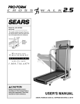
Thank you for selecting the PROFORM e CROSSWALK SI treadmill. The CROSSWALK SI treadmill
blends advanced technology with innovative design to
let you enjoy an excaUent.form_ofcardiovascular exercise in the convenience and privacy of your home.
For your benefit, read this manual carefully before
usingthe treadmill. If you have additlonal:questions,
please call our toil-free HELPLINE at 1-800-736-6879,
Monday throug.hSaturday, 7 a.m. until 7 p.m. Central
Time (excluding hoiidays). To help us assist you,
please note the product model number and sedal number before calling. The model number of the treadmill
is 831.297363. The sedal number can be found on a
decal attached to the treadmill (see the front cover of
this manual for the location).
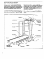
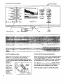
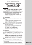
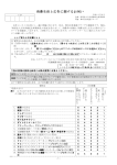
Before readlng further, please review the drawing
below and familiarize yourself with the parts that are
labeled.
;I Rack
Book Rack\
Console_
\
,_¢_essoryTray
Holder 0Nater
Bottle is not
included)
Storag_
Jpper Body
Arms
Handrails
FRONT
Walking Belt_
Foot Rails
Circuit Breaker
BACK
Rear Roller
Adiustment Bolt
4
Platform
ASSEMBLY
CAUTION: Read and follow step I below before removing the restraining tie (see drawing 1). If the restraining tie is removed prematurely, serious bodily injury may result. Assembly requires two people. Set the treadmill in a cleared area and remove the packing materials except for the restraining tie. Do not dispose of the
packing materials until assembly is completed. Use the HARDWARE IDENTIFICA'I_ON CHART in the center of
this manual to identify the parts used in assembly. Assembly requires the included allen wrench L==--, a
phillips screwdriver .-=======C_,
a 318" wrench '_======O,
and two adjustable wrenches C_:=_.
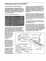
1. Slide the Left Upright (1) onto the left side of the Base
(59): It may be necessary to firmly push down on the
Left Upright until it is fully seated on the Base.
Remove the restraining tie from the Base.
Attach the left handrail to the Base (59) with a Handrail
Bolt (93), 3/8" Washer (67), and Handrail Nut (4). Do not
tighten the Handrail Bolt yet. Using a 3/8" wrench,
tighten two Upright Screws (63) into the Left Upright (1)
and the Base. Be sure to push on the heeds of the Upright
Screws while tightening them.
2. Slide the Right Upright (44) onto the right side of the
Base (59). It may be necessary to firmly push down
on the Right Upright until it is fully seated on the
Base. Be careful not to pinch the Wire Harness (25)
between the Right Upright and the Base.
Attach the right handrail to the Base (59) with a Handrail
Bolt (93), 3/8" Washer (67), and Handrail Nut (4). Do not
tighten the Handrail Bolt yet. Using a 3/8" wrench,
tighten two Upright Screws (63) into the Right Upright
(44) and the Base. Be sure to push on the heads of the
Upright Screws while tightening them.
Hand tighten the Handrail Nuts (4) used in steps 1 and 2.
Using a wrench, tighten the Handrail Bolts (93) used in
st-_s +,and 2. F_e_c_ _ the wir_ _ies (not shown) attaching the Console Base (9) to the Right Upright (44).
63
59
3. Set the Console Base (9) on the Left and Right Uprights
(1,44). Attach the Console Base with four Screws (75).
While one person carefully feeds any slack Wire Harness
(25) down into the Right Upright (44), a second pe_on
should carefully pull the slack Wire Harness from the
lower end of the Right Upright.
Align the holes in the Book Rack (62) with those in the
Console Base (9). Attach the Book Rack to the Console
Base with four Screws (75) as shown.
75
75
5
-!.V,;i_.h
thehe(pofa secondperson,
care_u(ty
!cwet_e Le_
and RightUprights
(I,4.4)
until
theha.ndrails
ereresting
on thefloor.
,
Attach six Base Pads (57) to the bottom of the Base (59)
in the indicated locations. Note: One extra Base Pad is
included.
(Gee (.irawing 4 above.) Witn the help oi a second person,
raise the Left and Right Uprights (1,4.4) until the Base
(_;_) is resting ilat on the _loor.
Before moving the treadmill, see HOW TO MOVE THE
TREADMILL on page 11.
,
Remove the Resistance Knob (97). 3/8" Washers (67).
Spring Washer (5), Thrust Washers (101), Thrust Bearing
(102), and Resistance Cone (98) from the Resistance
Bolt (105). P,=....... _ :'. ,- .:: :arts in order. Inset: : "':
:i :_, :_:" ,," :'-.-": -',:: ": ,":_!" ; ':o the Resistance Cone
,,. _, _;:._. ,_ :.:r-; _;::.: :: :c :'.. _,d as shown. Slide all
parts back onto the Resistance Bolt (105). Refer to the
HARDWARE IDENTIFICATION CHART to make sure
that all parts are in the correct order..'Tights.,:, the
Insert two Resistance Bracket Bolts (107) with Bracket
Washers (103), a Spacer (106), and _o more Star
Washers (103) onto the Bolts. Tighten the Bolts into the
Resistance Bracket (104). (Note: It may be necessary to
!o=,;_n _ha Resistance Kncb, [97j and pivot. :he
Resistance Bracket.)
Attach the other Upper Body Arm (96) as described
above, Make sure that both Upper Body Arms are in the
position shown on page 4. Refer to drawing 2 on page 5.
Feed the slack Wire Harness (25) into the Base (59).
7. Remove the backln_ ;ram the Adh,_'ve Clip (77). Press
.the Adhesive C|=ponlo _e Rear Ro_ler Endcap (78) in the
. indicated location. Press the Allen Wrench (76) into the
Adhesive C._p.
6
Make sure that all parts are tightened before you use the
tteadm.,ilL Hot_: To protect the flock',ot carpet, place a
mat under the treadmill For information on ordering a
mat, see REPLACEMENT PARTS on the back cover.
6
OPERATION
THE PERFORMANT
AND ADJUSTMENT
LUBE :=WALKING BELT
Your treadmill.features
a walking belt coated with
PERFORMANT LUBE_; a high-performanca lubdcant.
IMPORTANT: Never apply silicone spray or other
substances to the walking belt or the walking platform. They will deteriorate the walking belt and
cause excessive wear.
electdc shock. This product is equipped with a cord
having an equipment-grounding conductor and a
grounding plug. Plug the power cord into a surge
protector, and plug_he surge protector into an appropriate outlet that is properly installed and
grounded in accordance with all local codes and
ordinances.
This product is for use on a nominal 120-volt cimuit,
and has a grounding plug that looks like the plug illustrated in drawing 1 below. A temporary adapter that
looks like the adapter illustrated in drawing 2 may be
used to connect the surge protector to a 2-pole receptacle as shown in drawing 2 if a properly grounded outlet is not available.
HOW TO PLUG IN THE POWER CORD
The temporary adapter should be used only until a
properly grounded outlet (drawing 1) can be installed
by a qualified electrician.
The green.colored dgid ear, lug, or the like extending
from the adapter must be connected to a permanent
ground such as a properly grounded outlet box cover.
Whenever the adapter is used it must be held in place
by a metal screw. Some 2-pole receptacle outlet box
covers are not grounded. Contact a qualified electrician to determine if the outlet box cover is
Your treadmill, like any other type of sophisticated
electronic equipment, can be seriously damaged by
sudden voltage changes in your home's power.
Voltage surges, spikes, and noise interference can regrounded before using an adapter.
suit from weather conditions or from other appliances
being lumed on or off.
To decrease the possibility of your tread1
/Grounded
Outlet Box
mill being damaged,
Treadmill Power Cord-..
always use a surge
protector (not ini/Grounding
Pin
cluded) with your
Grounding Plug_
treadmitl.
"_unding
Surge protectors are
sold at moat hardware
stores and department
stores. Use only a UP-listed surge protector,
rated at 15 amps, with a
14-gauge cord of five
feet or less in length.
This product must be
grounded. If it should
malfunction or break
down, grounding provides a path of least resistance for electric current to reduce the risk of
Plug
_Grounded Outlet
Surge Protector
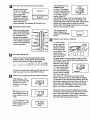
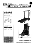
D AGRAM OFTHE
CONSOLE
,//f_Monitor Displays
1
Pulse
Sensor
BATI'ERY INS-TALLATION
STEP BY STEP CONSOLE OPERATION
The console requires three "AA" batteries (no( included). A:;.::_iine._.ttedes are recommended.
To install battef'ies, open the battery cover under the
console as shown below. Press three battedes into the
battery compartment
Before operating the console, make sure that the power
cord is propedy plugged in. (See HOW TO PLUG IN
THE POWER CORD on page 7.) If there is a thin sheet
of clear plastic on the face of the console, remove it.
i__k_ '-;_r e
Battery
thatthe:
neg-
Next., step onto :,;_ ,..............
_,;= _:=.edmill. Find the
clip _tteched to the key (see the drawing above), and
slide the clip onto the waistband of your clothing.
_,_ive(-)
ends of the
batteries are
touching the
• springs.
Close the
better! cover,
8
Follow the steps on page 9 to operate the console.
'_ieries
[!
Insert the key fully into the power switch.
CALORIES/FAT CALArrows
ORIES/PULSE
die play--This display
shows the approximate
C,_LS./ FAT CAL._
numbers of caiodes and
I_Jt.SE
fat ca/odes you have
burned. (See FAT
CALORIES onpa.ge 14 for an explanation of fat
calories.) Every seven seconds, the display will
change from one number to the other. Arrows in the
display will indicate which number is currently
shown. Note: This display will also show your pulse
when the pulse sensor is used.
Inserting the key will
not turn on the displ__,./s.The displays will
turn on when the
ON/RESET button is
pressed or When the
walking belt is started.
Note: If you just installed battedes, the displays will already be on.
E!
Reset the speed control.
Slide the speed control
down to the RESETposition. Note: Each time
the walking belt is
stopped, the speed
control must be moved
The displays can be
reset, if desired, by
pressing the ON/RESET
button.
la
to the RESET position
before the walking belt
can be restarted.
F!
Start the walking belt.
A_er you have moved the speed control to the
RESET position, slowly slide it upward until the
w_lking belt begins to move at slow speed.
,i'._ "_ ::!., _;:-;_::=': : "_'_wr.-.!!dn,"'::)!t .".ridb_._!n exercisir:G. C;hange t;._r_speed of the w_.l:_:irlgbe{t as de-
To stop the walking belt, step onto the foot rails and
slide the speed control to the RESET position.
B
Followyour
progress with the monitor displays.
display shows the total
time that you have
TIME
walkeddisplay--This
or run on the
tre_.dmill.
[
r.3',r'/.:_ FI1
_-L uj
T_WE :
L'-
!
Pulse
place your thumb
on the pulse sensor as shown. The
pulse sensor is
pressure-activated;
fu!ly press down
the pulse sensor. Do not press too hard, or the
circulation in your thumb will be restricted, and
your pulse will not be
detected. Next, slightly
raise your thumb until
the heart-shaped indicator in the CALORIES/
FAT CALORIES/PULSE
Indicator
S,/FATOg_.
SPEED
I
display flashes steadily.
Hold your thumb at this
level. After 5 to 10 seconds, your pulse will be
shown. Hold your thumb on the sensor for another
15 seconds for the most accurate reading. If the displayed pulse appears to be too high or too low, or if
yourjoulse is not displayed, lift your thumb off the
sensor and allow the display to reset. Press down
again on tl_e sensor as desc,'ibed above.
Make sure that your thumb is positioned as shown,
and that you are applying the proper amount of pressure to the pulse sensor. Try the sensor several
times until you become familiar with it. Remember to
stand stillwhile measuring your pulse.
This display shcw_ the
total distance that you
have walked or run, in
miles.
3FEED display_This
display shows the speed
of the walking belt, in
miles per hour.
Measure your pulse, if desired.
To use the pulse
sensor, stand on
the foot rails and
'3,J
ON/R_SET
When you are finished exercising, stop the
walking belt and remove the key..
Step onto the foot rails,
stop the walking belt,
and remove the key
from the console. Store
the key in a:secure
place_ After the,key is
removed, the displays
_wlll remaln'on for •
about five minutes.
To vary the intensity of your upper body exercise, the
resistance of the upper body arms can be adjusted. To
increase the resistance, turn the resistance knobs clockwise; to decrease the resistance, turn the knobs court°
terclockwise.
k
HOW TOCHANGE
lyl
Note: Any time that the walking belt is stopped
and no console buttons are pressed for five minutes, the displays will automatically turn off in
order to conserve the batteries.
HOW TO USE THE UPPER BODY ARMS
As you exercise on
the treadmill, you
can hold either the
handrails or the
upper body arms.
The upper body
arms are designed
to exercise your
arms, shoulders,
and back for a total
body workout. Hold
one upper body
arm with each
hand, and move
them forward and
back as you walk
-on the treadmill.
THE INCUNEOF
The incline of the treadmill can be changed by raising or
Iowedng the back end. Before changing the incline,
remove the key and unplug the power cord.
Hold the
rear roller
.endcap
with both
hands.
When the
back end
of the
treadmill is
in these locations
Leg
in the lowest position, the incline is about 10%. Raise the back end until it
clicks into position. (Note: It may be necessary to shake
the treadmill slightly so that it clicks into position.) The
incline will then be about 5%. Raise the back end again
until it clicks into position. The incline will then be about
3%. To lower the back end, first raise it past the highest
position, and then lower it. CAUTION: Before exerctsing, push on the back of the treadmill to make sure
that the incline legs are locked in position. Do not
place objects under the treadmill to change the incline; change the incline only as described above.
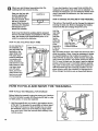
HOW TO FOLD AND MOVE THE TREADMILL
HOW TO FOLD THE TREADMILL
FOR STORAGE
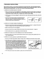
Before folding the treadmill, unplug the power cord. Caution:
You must be able to safely lift 45 pounds (20 kg) in order
to raise, lower, or move the treadmill.
1, Hold the treadmill with your hands in the locations shown
at the dght. To decrease the possibility of injury, bend "
your legs and keep your back straight. As you raise
the treadmill, make sure to lift with your legs rather
than your back. Raise the treadmill about halfway to the
vertical position.
10
THE TREADMILL
2. Move )'our right hand to the position shown and hold the
treadmill firmly. Raise the treadmill until the storage latch
closes over the frame guide. Make sure that the storage
latch closes fully over the frame guide.
To protect the floor or carpet from damage, place a
mat under the treadmill. Keep the treadmill out of direct sunlight. Do not leave the treadmiU In the storage
position in temperatures above 85 ° Fahrenheit.
HOW TO MOVE THE TREADMILL
Before moving the treadmill, convert the treadmill to the storage position as described above. Make sure that the storage latch is closed fully over the frame guide.
1. Hold the. !Jp_er ends of the handrails. Place one ;cot on
the base as shown.
2. Tilt the treadmill back un:il it rolls froely on the front wheels.
Carefully move the treadmill to the desired location. Never
move the treadmill without tipping it back, or the base
pads may come off. To reduce the risk of iniury , use
extreme caution while moving the treadmill. Do not ettempt to move the treadmill over an uneven surface.
3. Place one foot on the base. and carefully lower the treadmill until it is resting in the storage position.
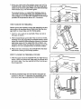
HOW TO LOWER THE TREADMILL
_"-Front
Wheels
FOR USE
1. Hold the upper end of the treadmill with your right hand as
shown. Using your left thumb, slide open the storage latch
and hold it open. Pivot the treadmill until the frame is past
the storage latch.
Closed
2. Hold the treadmill firmly with both hands, and lower the
• treadmill to the floor. To decrease the possibility of Injury, bend your legs and keep your back straight.
TROUBLE-SHOOTING
Most treadmill problems ca n be solved by following the simple steps below. Find the symptom that ap_
plies, and follow the steps listed. If further assistance is needed, call our toll-free HELPLINE at 1-800-7366879, Monday through Saturday, 7 a.m. until 7 p.m. Central Time (excluding holidays).•
1. sYMPToM:
THE PowER
DOES NOT TURN ON
• a. Make surethat the power cord is plugged into a surge protector, and that the surge protector is plugged into
.....
a properly grounded outlet. (See HOW TO PLUG IN THE POWER CORD on page 7,) Use only a UL-listed
surge protec.tor, rated at.15 amps with a 14-gauge cord of five feet or less in length.
b. After the power cord has been plugged in, make sure that the key is fully inserted into the console. (See step
1 on page 9.)
c. Check the circuit breaker located on the treadmill near the
power cord. If the switch protrudes as shown, the circuit
breaker has tripped. To reset the circuit breaker, wait for five
minutes and then press the switch back in.
2. SYMPTOM: THE POWER TURNS OFF DURING USE
a. Check the circuit breaker located on the treadmill frame near the power cord (see 1. c. above). If the circuit
breaker has tripped, wait for five minutes and then press the switch back in.
b. Make sure that the power cord is plugged in.
c. Remove the key from the console. Reinsert the key fully into the console. (See step 1 on page 9.)
d. If the treadmill still will not run, please call our toll-free HELPLINE.
3. SYMPTOM: THE DISPLAYS OF THE CONSOLE
DO NOT FUNCTION PROPERLY
a, Check the battedes in the console. (See BATI'ERY INSTALLATION on page 8.) Most problems are the result of drained bakeries.
4. SYMPTOM: THE WALKING BELT SLOWS WHEN WALKED ON
a. Use only a UL-listed surge protector, rated at 15 amps, with a 14-gauge cord of five feet or less in length.
b. If the walking belt is overtightened, treadmill performance may
decrease and the walking belt may be permanently damaged.
Remove the key and UNPLUG THE POWER CORD. Using the
allen wrench, turn both rear miler adjustment bolts counterclockwise, 1/4 of a turn. When the walking belt is propedy tightened,
you should be able to lift each side of the walking belt 2-3
inches oft the walking platform. The center of the walking belt
should just touch the walking platform. Be careful to keep the
walking belt centered. Plug in the power cord, insert the key and
run the treadmill for a few minutes. Repeat until the walking belt
is prcpedy tightened.
Rear Roller Adjustment Bolts
c. If the walking belt still slows when walked on, please call our toll-free HELPLINE.
12
5. SYMPTOM;
THE WALKING r._ELT IS OFF-CENTER
WHEN WALKED ON
a. If the walking belt has shifted to the left, first remove the key and
UNPLUG THE POWER CORD. Using the 3/16" end of the allen
wrench, tum the left rear roller adiustment bolt clockwise, and
the dght bolt counterclockwise, i/4 of a turn each. Be careful not
to over'tighten the walking belt. Plug in the power cord, insert the
key and run the treadmill for a few minutes. Repeat until the
walking belt is cantered.
b. If thewalking belt has shift_l to the dght, first remove the key
and UNPLUG THE POWER CORD. Using the 3/16" end of the
b
allen wrench, turn the left rear roller adjustment bolt counterclockwise, and the right bolt clockwise, 1/4 of a turn each. Be
careful not to over0ghten the walking belt. Plug in the power
cord, insert the key and run the treadmill for a few minutes.
Repeat until the walking belt is centered.
c. If the walking belt slips when walked on, first remove the key
and UNPLUG THE POWER CORD: Using the 3/16" end of the
allen wrench, turn both rear roller adjustment bolts clockwise,
1/4 of a turn. When the walking belt is correctly tightened, you
should be able to lift each side of the walking belt 2-3 inches off
the walking platform. The center of the walking belt should just
touch the walking platform. Be careful to keep the walking belt
centered. Plug in the power cord, insnrt.,the k.=y and run the
treadmill for a few minutes. Repeat u::::i{he walking belt is prop-
C
erly tightened.
6. SYMPTOM; THE TREADMILL
SITS UNEVENLY ON THE FLOOR
a. Make sure that the six base pads are a_ached to the treadmill (see assembly step 5 on page 6).
7. SYMPTOM; THE INCLINE SYSTEM STICKS
a. Raise the treadmill to the storage position. (See HOW TO FOLD THE TREADMILL
_.g-_ ;0.) Pivot the incline leg several times _ break in the incline system.
8. SYMPTOM;
FOR STORAGE
on
ONE OF THE UPPER BOOY ARMS SQUEAKS DURING USE
a. Correcting this problem requires a small amount of white madne grease, available at most hardware stores.
Turn the Resistance Knob (97) counterclockwise until it can be
rgmoved. Remove the Resistance Cone (98) and the Upper
Body Arm (96), along with the 3/8" Washers (67), Spring
Washer (5), Thrust Washers (101), and Thrust Beadng (102).
(Note: If the Resistance Sleeve [99] comes out of the
Resistance Bracket [104], preSS it back in.) Apply a thin layer of
white marine grease t_ the outer surface of the Resistance Cone
(98). Reattach all parts in the order shownat the right.
I
i
to, //
I '.-./9o /.L.-os
CONDITIONING
GUIDELINES
Fat Burning
To bum fat effectively, you must exercise ate relatively
low intensity level for a sustained period of time. During
the first few Minutes of exemise, your body uses easily
access_le carbohydrate calories for energy.Only after
the first few minutes does your body begin to use
stored fat calories for energy. If your goal is to bum fat,
adjust the speed and incline of the treadmill until your
heart rate is near one of the lower-two numbers in your
training zone. It may also be helpful to set the speed
control on the console to FAT BURN to help you maintain the proper intensity level: (See page 9.)
Aerobic Exercise
The following guidelines will help you to plan your exercise program. Remember--these are general guidelines only, For more detailed exercise information, obtain a reputabl e book or consu(t your physician.
EXERCISE INTENSITY
Whether your goal is to bum fat or to strengthen your
cardiovascular system, the key to achieving the desired results is to exercise with the proper intensity.
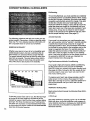
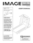
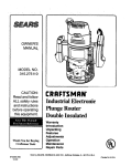
The proper intensity level can be found by using your
heart rate as a guide. The chart below shows recommended heart rates for fat burning and aerobic exercise. (This chart is also found on the console.)
20
30
40
50
60
70
80
b.p..',.
AGE
AEROBIC
MAX.FAT
FATBURN
HEART RATE TRAINING ZONES
If your goal is to strengthen your cardiovascular system, your exercise must be "aerobic." Aerobic exercise
is activity that requires large amounts of oxygen for
prolonged pedods of time. This increases the demand
on the heart to pump blood to the muscles, and on the
lungs to oxygenate the blood. For aerobic exercise,
adjust the speed end incline of the treadmill until your
heart rate is near the higher number in your training
zone. It may also be helpful to set the speed control on
the console to AEROBIC to help you maintain the
proper intensity level. (See page 9.)
High Performance Athletic Conditioning
If your goal is high performance athletic conditioning,
set the speed control on the console to PERFORMANCE to help you maintain the proper intensity level.
(See page 9.) Note: During the first few weeks of your
exercise program, keep your heart rate near the low
end of your training zone.
To-measure your heart rate during exercise, use the
pulse sensor on the console. (See page 9.) If your
heart rate is too high or too low, adjust the speed or inclir_e,of the treadmill until your heart rate is at the
proper level.
WORKOUT GUIDELINES
Each workout should include the following three important parts:
To find the proper heart rate for you, first find your age
at the top of the chart (ages are rounded off to the
nearest ten years). Next, find the three numbers below
your age. The three numbers are your "training zone."
The lower two numbers are recommended heart rates
for fat burning; the higher number is the recommended
heart rate for aerobic exercise.
114
A Warm-up
Start each workout by warming up for 5 to 10 minutes.
Begin with slow, controlled stretches, and progress to
more rhythmic stretches to increase your body temperature, heart rate, and circulation in preparation for
strenuous exercise.
Training
Zone Exercise
After warming up, increase the intensity of your exercise until your hea_ rate is in your training zone for 20
to 60 minutes: (Dudng the first few weeks of your exercise program, do not keep your heart rate in your training zone for longer than 20 minutes;) Breathe regularly
and deeply as you exercise---never hold your breath.
to cool down. This will increase the flexibility of your
muscles and will help to prevent post-exercise problems.
Exercise Frequency
To maintain or improve your condition, complete throe
workouts each week, with at least one day of rest between workouts. After,.afew months, you may complete up to five workouts each week if desired,
A Cool-down
Finish each workout with 5 to 10 minutes of strotchlng
SUGGESTED
The t;.3y _ Z,uccess is to make exercise a regular and
enjoyable part of your everyday life.
STRETCHES
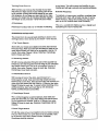
The correct form for several basic stretches is shown in the
drawings below. Move slowly as you strotch--never bounce.
1. Toe Touch Stretch
Stand with your knees bent slightlyand slowly bend forward
from your hips, Allow your back and shoulders to relax as you
reach down toward your toes as far as possible. Hold for 15
• counts, then relax. Repeat 3 times. Stretches: Hamstrings,
back of knees and back.
2. Hamstring Stretch
Sit with one leg extended. Bring the sole of the opposite foot
toward you and rest it against the inner thigh of your extended
leg. Reach toward your toes as far as possible. Hold for 15
counts, then relax. Repeat 3 times for each leg. Stretches:
Hamstrings, lower back and groin.
3. Calf/Achilles
Stretch
With one leg in front of the other, reach forward an,_ _;._,:._.
hands against a wall. Keep your back leg straight and your
bacl;: foot flat on the floor. Bend your front leg, lean forward and
move your hips toward the wall. Hold for 15 counts, then relax.
Repeat 3 times_for each leg. To cause further stretching of the
achilles tendons, bend your back leg as well. Stretches:
Calves, achilles tendons and ankles.
4. Quadriceps
3
Stretch
Wi_h une hand against a wall for balance, roach back and
grasp one foot with your other hand. Bring your heat as close
to your buttocks as possible. Hold for 15 counts, then relax.
Repeat 3 times for each leg. Stretches: Quaddceps and hip
muscle,_.
5. Inner Thigh Stretch
Sit with the soles of your feet together and your knees outward.
Pull your feet toward your groin area as far as possible. Hold
for15 counts, then relax. Repeat 3 times. Stretches:
• Quadriceps and hip muscles.
4
8E/AUR8
The model number and sedal number of your PROFORM ° CROSSWALK SI treadmill are listed on a decal attached to the frame; See
the front cover of this•manual to find thelocation of the decal.
Moci lNo.831. 87363
QUESTIONS?
All replacement pads are available for immediate purchase or
if you find that:
special order when you visit your nearest SEARS Service Center.
To request service or to order pads by telephone, call thetoll-free
numbers listed at the left.
• you need help assembling
operating the PROFORkP
CROSSWALK SI treadmill
or
• a part is missing
• or you need to schedule repair
service
call our toll,free
When requesting help or service, orordedng parts, please be prepared to provide the following information:
• The NAME OF THE PRODUCT
treadmill)
(PROFORM e CROSSWALK
SI
• The MODEL NUMBER OF THE PRODUCT (831.297363)
HELPLINE
1-800-736-6879
Monday-Saturday,
7 am-7 pm
Central Time (excluding holidays)
• The PART NUMBER OF THE PART (sea the EXPLODED
DRAWING and PART LiST included in this manuel)
• The DESCRIPTION OF THE PART (see the EXPLODED DRAWING and PART LIST included in this manual).
REPLACEMENT
PARTS
If parts become worn and need
to be replaced, call the following
toll-free number
1-800-FON-PART
(1-800-386-7278)
FULL 90 DAY:WARRANTY
For 90 days from the date of pUrcl_ase, if failure occurs due to defect in material or workmanship in this
SEARS TREADMILL EXERCISER, contact the nearest SEARS Service Center throughout the United
States end SEARS will repair or replace the TREADMILL EXERCISER, free of charge.
This warranty does not apply when the TREADMILL EXERCISER is Used commemially or for rental pur*
poses.
This warranty gives you specific legal rights, and you may also have other rights which vary from state
to state.
SEARS, ROEBUCK AND CO., DEPT. 817WA, HOFFMAN
Part No. 132579 F03191AC
R0996B
ESTATES, iL 60179
Pdnted in USA @";1996 Sears, RoebuCk and Co.