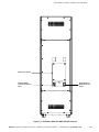
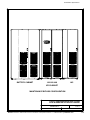
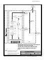
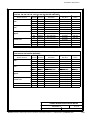
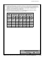
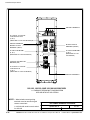
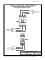
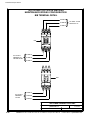
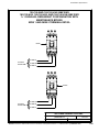
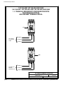
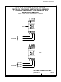
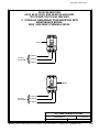
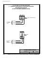
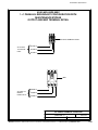
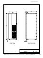
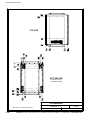
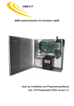
1
Powerware 9390 Integrated Accessory Cabinet IAC-B and IAC-T Configurations Installation and Operation Manual ® For use with Powerware 9390 40–80 kVA and 100–160 kVA UPS Models IMPORTANT SAFETY INSTRUCTIONS SAVE THESE INSTRUCTIONS This manual contains important instructions that you should follow during installation and maintenance of the UPS and batteries. Please read all instructions before operating the equipment and save this manual for future reference. Consignes de sécurité CONSIGNES DE SÉCURITÉ IMPORTANTES CONSERVER CES INSTRUCTIONS CE MANUEL CONTIENT DES CONSIGNES DE SÉCURITÉ IMPORTANTES Powerware is a registered trademark of Eaton Electrical Inc. ECopyright 2005-2006 Eaton Corporation, Raleigh, NC, USA. All rights reserved. No part of this document may be reproduced in any way without the express written approval of Eaton Corporation. Table of Contents 1 Introduction . . . . . . . . . . . . . . . . . . . . . . . . . . . . . . . . . . . . . . . . . . . . . . . . . . . . . . . . . . . . 1-1 1.1 Configurations . . . . . . . . . . . . . . . . . . . . . . . . . . . . . . . . . . . . . . . . . . . . . . . . . . . . . . . . . . . . 1-1 1.2 Using This Manual . . . . . . . . . . . . . . . . . . . . . . . . . . . . . . . . . . . . . . . . . . . . . . . . . . . . . . . . . 1-3 1.3 Conventions Used in This Manual . . . . . . . . . . . . . . . . . . . . . . . . . . . . . . . . . . . . . . . . . . . . 1-4 1.4 Safety Warnings . . . . . . . . . . . . . . . . . . . . . . . . . . . . . . . . . . . . . . . . . . . . . . . . . . . . . . . . . . . 1-5 1.5 For More Information . . . . . . . . . . . . . . . . . . . . . . . . . . . . . . . . . . . . . . . . . . . . . . . . . . . . . . 1-6 1.6 Getting Help . . . . . . . . . . . . . . . . . . . . . . . . . . . . . . . . . . . . . . . . . . . . . . . . . . . . . . . . . . . . . . 1-6 Section I – Installation 2 IAC Installation Plan and Unpacking . . . . . . . . . . . . . . . . . . . . . . . . . . . . . . . . . . . . . . 2-1 2.1 Creating an Installation Plan . . . . . . . . . . . . . . . . . . . . . . . . . . . . . . . . . . . . . . . . . . . . . . . . . 2-1 2.2 Preparing the Site . . . . . . . . . . . . . . . . . . . . . . . . . . . . . . . . . . . . . . . . . . . . . . . . . . . . . . . . . 2-1 2.2.1 Environmental Considerations . . . . . . . . . . . . . . . . . . . . . . . . . . . . . . . . . . . . . . . . . . . 2-2 2.2.2 Preparing for Wiring the IAC . . . . . . . . . . . . . . . . . . . . . . . . . . . . . . . . . . . . . . . . . . . . . 2-2 2.3 3 Inspecting and Unpacking the IAC . . . . . . . . . . . . . . . . . . . . . . . . . . . . . . . . . . . . . . . . . . . 2-3 Installing the IAC . . . . . . . . . . . . . . . . . . . . . . . . . . . . . . . . . . . . . . . . . . . . . . . . . . . . . . . 3-1 3.1 Preliminary Installation Information . . . . . . . . . . . . . . . . . . . . . . . . . . . . . . . . . . . . . . . . . . 3-1 3.2 Unloading the Powerware 9390 IAC from the Pallet . . . . . . . . . . . . . . . . . . . . . . . . . . . . . 3-1 3.3 IAC Cabinet Installation – Maintenance Bypass Configuration . . . . . . . . . . . . . . . . . . . . . 3-5 3.3.1 Line-up-and-Match MBP IAC Installation . . . . . . . . . . . . . . . . . . . . . . . . . . . . . . . . . . . 3-5 3.3.2 Installing IAC Line-up-and-Match MBP Power Wiring . . . . . . . . . . . . . . . . . . . . . . . . 3-10 3.3.3 Standalone MBP IAC Installation . . . . . . . . . . . . . . . . . . . . . . . . . . . . . . . . . . . . . . . . . . 3-12 3.3.4 Installing IAC Standalone MBP Power Wiring . . . . . . . . . . . . . . . . . . . . . . . . . . . . . . . 3-14 3.3.5 Installing IAC MBP TB1 Interface Connections . . . . . . . . . . . . . . . . . . . . . . . . . . . . . . 3-16 3.4 IAC Cabinet Installation – 1+1 Parallel Redundant Configuration . . . . . . . . . . . . . . . . . . 3-17 3.4.1 Line-up-and-Match Parallel IAC Installation . . . . . . . . . . . . . . . . . . . . . . . . . . . . . . . . 3-17 3.4.2 Installing IAC Line-up-and-Match Parallel Power Wiring . . . . . . . . . . . . . . . . . . . . . . 3-24 3.4.3 Standalone Parallel IAC Installation . . . . . . . . . . . . . . . . . . . . . . . . . . . . . . . . . . . . . . . 3-26 3.4.4 Installing IAC Standalone Parallel Power Wiring . . . . . . . . . . . . . . . . . . . . . . . . . . . . . 3-28 3.4.5 Installing IAC MBP and MOB TB1 Interface Connections . . . . . . . . . . . . . . . . . . . . . . 3-30 3.5 Initial Startup . . . . . . . . . . . . . . . . . . . . . . . . . . . . . . . . . . . . . . . . . . . . . . . . . . . . . . . . . . . . . 3-31 3.6 Completing the Installation Checklist . . . . . . . . . . . . . . . . . . . . . . . . . . . . . . . . . . . . . . . . . 3-31 EATON Powerware® 9390 IAC-B and IAC-T Installation and Operation Manual S 164201590 Rev C powerware.com i Table of Contents Section II – Operation 4 Understanding IAC Operation . . . . . . . . . . . . . . . . . . . . . . . . . . . . . . . . . . . . . . . . . . . . 4-1 4.1 4.1.1 UPS Mode . . . . . . . . . . . . . . . . . . . . . . . . . . . . . . . . . . . . . . . . . . . . . . . . . . . . . . . . . . . . 4-1 4.1.2 Maintenance Bypass Mode . . . . . . . . . . . . . . . . . . . . . . . . . . . . . . . . . . . . . . . . . . . . . . 4-2 4.2 5 Parallel Redundant Configuration . . . . . . . . . . . . . . . . . . . . . . . . . . . . . . . . . . . . . . . . . . . . 4-3 4.2.1 Redundant Operation . . . . . . . . . . . . . . . . . . . . . . . . . . . . . . . . . . . . . . . . . . . . . . . . . . 4-3 4.2.2 Redundant Operation with Maintenance Bypass – UPS Mode . . . . . . . . . . . . . . . . . 4-4 4.2.3 Redundant Operation with Maintenance Bypass – Bypass Mode . . . . . . . . . . . . . . . 4-5 IAC Features, Options, Controls, and Operation . . . . . . . . . . . . . . . . . . . . . . . . . . . 5-1 5.1 IAC Standard Features . . . . . . . . . . . . . . . . . . . . . . . . . . . . . . . . . . . . . . . . . . . . . . . . . . . . . 5-1 5.1.1 Maintenance Bypass Configuration . . . . . . . . . . . . . . . . . . . . . . . . . . . . . . . . . . . . . . . 5-1 5.1.2 Parallel Redundant Configuration . . . . . . . . . . . . . . . . . . . . . . . . . . . . . . . . . . . . . . . . . 5-1 5.1.3 Parallel Redundant Configuration with Maintenance Bypass . . . . . . . . . . . . . . . . . . 5-1 5.1.4 Customer Interface . . . . . . . . . . . . . . . . . . . . . . . . . . . . . . . . . . . . . . . . . . . . . . . . . . . . . 5-1 5.1.5 Installation Features . . . . . . . . . . . . . . . . . . . . . . . . . . . . . . . . . . . . . . . . . . . . . . . . . . . . 5-1 5.1.6 Expansion . . . . . . . . . . . . . . . . . . . . . . . . . . . . . . . . . . . . . . . . . . . . . . . . . . . . . . . . . . . . . 5-1 5.2 ii Maintenance Bypass Configuration . . . . . . . . . . . . . . . . . . . . . . . . . . . . . . . . . . . . . . . . . . . 4-1 Options . . . . . . . . . . . . . . . . . . . . . . . . . . . . . . . . . . . . . . . . . . . . . . . . . . . . . . . . . . . . . . . . . . 5-2 5.2.1 Bypass Input Breaker . . . . . . . . . . . . . . . . . . . . . . . . . . . . . . . . . . . . . . . . . . . . . . . . . . . 5-2 5.2.2 Rectifier Input Breaker . . . . . . . . . . . . . . . . . . . . . . . . . . . . . . . . . . . . . . . . . . . . . . . . . . 5-2 5.2.3 System Load Breaker . . . . . . . . . . . . . . . . . . . . . . . . . . . . . . . . . . . . . . . . . . . . . . . . . . . 5-2 5.3 Symbols . . . . . . . . . . . . . . . . . . . . . . . . . . . . . . . . . . . . . . . . . . . . . . . . . . . . . . . . . . . . . . . . . 5-3 5.4 IAC Controls . . . . . . . . . . . . . . . . . . . . . . . . . . . . . . . . . . . . . . . . . . . . . . . . . . . . . . . . . . . . . . 5-4 5.5 IAC Operation – Maintenance Bypass Configuration . . . . . . . . . . . . . . . . . . . . . . . . . . . . 5-9 5.5.1 Using the UPS when an IAC is Installed . . . . . . . . . . . . . . . . . . . . . . . . . . . . . . . . . . . . 5-9 5.5.2 Transferring the UPS to Maintenance Bypass . . . . . . . . . . . . . . . . . . . . . . . . . . . . . . . 5-9 5.5.3 Transferring the UPS from Maintenance Bypass . . . . . . . . . . . . . . . . . . . . . . . . . . . . . 5-10 5.6 IAC Operation – Parallel Redundant Configuration . . . . . . . . . . . . . . . . . . . . . . . . . . . . . . 5-11 5.7 IAC Operation – Parallel Redundant Configuration with Maintenance Bypass . . . . . . . 5-11 EATON Powerware® 9390 IAC-B and IAC-T Installation and Operation Manual S 164201590 Rev C powerware.com Table of Contents 6 7 Maintaining the IAC . . . . . . . . . . . . . . . . . . . . . . . . . . . . . . . . . . . . . . . . . . . . . . . . . . . . . 6-1 6.1 Important Safety Instructions . . . . . . . . . . . . . . . . . . . . . . . . . . . . . . . . . . . . . . . . . . . . . . . . 6-1 6.2 Performing Preventive Maintenance . . . . . . . . . . . . . . . . . . . . . . . . . . . . . . . . . . . . . . . . . . 6-1 6.2.1 DAILY Maintenance . . . . . . . . . . . . . . . . . . . . . . . . . . . . . . . . . . . . . . . . . . . . . . . . . . . . 6-1 6.2.2 PERIODIC Maintenance . . . . . . . . . . . . . . . . . . . . . . . . . . . . . . . . . . . . . . . . . . . . . . . . . 6-2 6.2.3 ANNUAL Maintenance . . . . . . . . . . . . . . . . . . . . . . . . . . . . . . . . . . . . . . . . . . . . . . . . . . 6-2 6.3 Short Circuits . . . . . . . . . . . . . . . . . . . . . . . . . . . . . . . . . . . . . . . . . . . . . . . . . . . . . . . . . . . . . 6-2 6.4 Recycling the Used IAC . . . . . . . . . . . . . . . . . . . . . . . . . . . . . . . . . . . . . . . . . . . . . . . . . . . . . 6-2 6.5 Maintenance Training . . . . . . . . . . . . . . . . . . . . . . . . . . . . . . . . . . . . . . . . . . . . . . . . . . . . . . 6-2 Product Specifications . . . . . . . . . . . . . . . . . . . . . . . . . . . . . . . . . . . . . . . . . . . . . . . . . . . 7-1 7.1 Model Number . . . . . . . . . . . . . . . . . . . . . . . . . . . . . . . . . . . . . . . . . . . . . . . . . . . . . . . . . . . 7-1 7.2 IAC Input . . . . . . . . . . . . . . . . . . . . . . . . . . . . . . . . . . . . . . . . . . . . . . . . . . . . . . . . . . . . . . . . 7-1 7.3 IAC Output . . . . . . . . . . . . . . . . . . . . . . . . . . . . . . . . . . . . . . . . . . . . . . . . . . . . . . . . . . . . . . . 7-1 7.4 Environmental Specifications . . . . . . . . . . . . . . . . . . . . . . . . . . . . . . . . . . . . . . . . . . . . . . . . 7-1 Appendix A – Installation Information . . . . . . . . . . . . . . . . . . . . . . . . . . . . . . . . . . . . . . . . . A-1 Warranty . . . . . . . . . . . . . . . . . . . . . . . . . . . . . . . . . . . . . . . . . . . . . . . . . . . . . . . . . . . . . . . . . . . W-1 EATON Powerware® 9390 IAC-B and IAC-T Installation and Operation Manual S 164201590 Rev C powerware.com iii Table of Contents This page intentionally left blank. iv EATON Powerware® 9390 IAC-B and IAC-T Installation and Operation Manual S 164201590 Rev C powerware.com List of Figures Figure 1-1. Powerware 9390 IAC . . . . . . . . . . . . . . . . . . . . . . . . . . . . . . . . . . . . . . . . . . . . . . . . . . . . . . . . 1-2 Figure 2-1. Powerware 9390 IAC as Shipped on Pallet . . . . . . . . . . . . . . . . . . . . . . . . . . . . . . . . . . . . . . 2-3 Figure 3-1. Removing the Front Shipping Bracket on the Powerware 9390 IAC . . . . . . . . . . . . . . . . . 3-3 Figure 3-2. Removing the Rear Shipping Bracket on the Powerware 9390 IAC . . . . . . . . . . . . . . . . . 3-4 Figure 3-3. 40–80 kVA UPS with Line-up-and-Match IAC . . . . . . . . . . . . . . . . . . . . . . . . . . . . . . . . . . . 3-5 Figure 3-4. 100–160 kVA UPS with Line-up-and-Match IAC . . . . . . . . . . . . . . . . . . . . . . . . . . . . . . . . . 3-6 Figure 3-5. 40–80 kVA UPS to IAC Joining Brackets . . . . . . . . . . . . . . . . . . . . . . . . . . . . . . . . . . . . . . . . 3-8 Figure 3-6. 100–160 kVA UPS to IAC Joining Brackets . . . . . . . . . . . . . . . . . . . . . . . . . . . . . . . . . . . . . . 3-9 Figure 3-7. 40–80 kVA UPS with Standalone IAC . . . . . . . . . . . . . . . . . . . . . . . . . . . . . . . . . . . . . . . . . . 3-12 Figure 3-8. 100–160 kVA UPS with Standalone IAC . . . . . . . . . . . . . . . . . . . . . . . . . . . . . . . . . . . . . . . . 3-13 Figure 3-9. Two 40–80 kVA UPMs with Line-up-and-Match IAC . . . . . . . . . . . . . . . . . . . . . . . . . . . . . . 3-17 Figure 3-10. Two 100–160 kVA UPMs with Line-up-and-Match IAC . . . . . . . . . . . . . . . . . . . . . . . . . . 3-18 Figure 3-11. 40–80 kVA UPM 1 to IAC Joining Brackets . . . . . . . . . . . . . . . . . . . . . . . . . . . . . . . . . . . . 3-20 Figure 3-12. IAC to 40–80 kVA UPM 2 Joining Brackets . . . . . . . . . . . . . . . . . . . . . . . . . . . . . . . . . . . . 3-21 Figure 3-13. 100–160 kVA UPM 1 to IAC Joining Brackets . . . . . . . . . . . . . . . . . . . . . . . . . . . . . . . . . . 3-22 Figure 3-14. IAC to 100–160 kVA UPM 2 Joining Brackets . . . . . . . . . . . . . . . . . . . . . . . . . . . . . . . . . . 3-23 Figure 3-15. Two 40–80 kVA UPMs with Standalone IAC . . . . . . . . . . . . . . . . . . . . . . . . . . . . . . . . . . . 3-26 Figure 3-16. Two 100–160 kVA UPMs with Standalone IAC . . . . . . . . . . . . . . . . . . . . . . . . . . . . . . . . . 3-27 Figure 4-1. Path of Current Through the IAC in UPS Mode . . . . . . . . . . . . . . . . . . . . . . . . . . . . . . . . . 4-1 Figure 4-2. Path of Current Through the IAC in Maintenance Bypass Mode . . . . . . . . . . . . . . . . . . . . 4-2 Figure 4-3. Path of Current Through the IAC during Redundant Operation . . . . . . . . . . . . . . . . . . . . 4-3 Figure 4-4. Path of Current Through the IAC during Redundant Operation in UPS Mode . . . . . . . . 4-4 Figure 4-5. Path of Current Through the IAC during Redundant Operation in Bypass Mode . . . . . . 4-5 Figure 5-1. Powerware 9390 IAC MBP and MIS Controls . . . . . . . . . . . . . . . . . . . . . . . . . . . . . . . . . . . . 5-5 Figure 5-2. Powerware 9390 IAC MBP, MIS, BIB, and RIB Controls . . . . . . . . . . . . . . . . . . . . . . . . . . . . 5-6 Figure 5-3. Powerware 9390 IAC MOB 1, MOB 2, and SLB Controls . . . . . . . . . . . . . . . . . . . . . . . . . . 5-7 Figure 5-4. Powerware 9390 IAC MOB 1, MOB 2, MBP, and MIS Controls . . . . . . . . . . . . . . . . . . . . . 5-8 EATON Powerware® 9390 IAC-B and IAC-T Installation and Operation Manual S 164201590 Rev C powerware.com v This page intentionally left blank. vi EATON Powerware® 9390 IAC-B and IAC-T Installation and Operation Manual S 164201590 Rev C powerware.com Chapter 1 Introduction The Powerware® 9390 Integrated Accessory Cabinet (IAC) is designed for use with the Powerware 9390 40–80 kVA and 100–160 kVA three-phase uninterruptible power systems (UPSs). The IAC provides maintenance bypass, parallel tie cabinet, or parallel tie cabinet with maintenance bypass functions with the following custom configurable features, enabling adaptation and expansion without costly electrical rework: 쑺 Maintenance Bypass Configuration – Maintenance Bypass (MBP) and Maintenance Isolation (MIS) breakers enable power to completely bypass the UPS power module. The UPS module can then be safely serviced or replaced without interrupting power to critical systems. An optional Bypass Input Breaker (BIB) and Rectifier Input Breaker (RIB) provide a single wiring point input to the UPS as well as a convenient method for removing power from the UPS when using the maintenance bypass to supply the load. 쑺 Parallel Redundant Configuration – Module Output Breakers (MOB) 1 and 2 enable two UPS modules to be paralleled together for redundancy. An optional System Load Breaker (SLB) provides output control to the critical load for the whole system. 쑺 Parallel Redundant Configuration with Maintenance Bypass – Module Output Breakers (MOB) 1 and 2 enable two UPS modules to be paralleled together for redundancy. Optional Maintenance Bypass (MBP) and Maintenance Isolation (MIS) breakers enable power to completely bypass the UPS power module. The IAC is housed in a single, free-standing cabinet, with safety shields behind the doors for hazardous voltage protection. The cabinet matches the UPS cabinet in style and color, and can be installed in line-up-and-match or standalone configurations. Figure 1-1 shows the Powerware 9390 IAC. 1.1 Configurations The following IAC configurations are possible: 쑺 IAC with MBP and MIS 쑺 IAC with MBP, MIS, and BIB 쑺 IAC with MBP, MIS, BIB, and RIB 쑺 IAC with MOB 1 and MOB 2 쑺 IAC with MOB 1, MOB 2, and SLB 쑺 IAC with MOB 1, MOB 2, MBP, and MIS EATON Powerware® 9390 IAC-B and IAC-T Installation and Operation Manual S 164201590 Rev C powerware.com 1-1 Introduction Figure 1-1. Powerware 9390 IAC 1-2 EATON Powerware® 9390 IAC-B and IAC-T Installation and Operation Manual S 164201590 Rev C powerware.com Introduction 1.2 Using This Manual This manual describes how to install and operate the Powerware 9390 160 kVA IAC. Read and understand the procedures described in this manual to ensure trouble-free installation and operation. The information in this manual is divided into the sections and chapters listed. At a minimum, Chapters 1 through 3 and Chapter 5 should be examined. 쑺 Chapter 1, “Introduction” – provides a brief description of the IAC, a description of the content of each chapter, text conventions used in the manual, safety warnings, and reference information. Section I, Installation 쑺 Chapter 2, “IAC Installation Plan and Unpacking” – explains how to prepare the site for the installation of the IAC. It discusses equipment environmental requirements, inspecting, and unpacking cabinets. 쑺 Chapter 3, “Installing the IAC” – describes how to install and wire the IAC. Section II, Operation 쑺 Chapter 4, “Understanding IAC Operation” – provides information on how an IAC works. 쑺 Chapter 5, “IAC Features, Controls, and Operation” – describes the standard and optional IAC features, the IAC controls, and how to use the IAC. 쑺 Chapter 6, “Maintaining the IAC” – contains maintenance instructions for the IAC. 쑺 Chapter 7, “Product Specifications” – provides specifications for the IAC. 쑺 Appendix A, “Installation Information” – contains important information on wiring requirements and recommendations, and important diagrams of the cabinets’ mechanical details and electrical access. 쑺 Warranty – provides the Eaton warranty for this product. Read through each procedure before beginning the procedure. Perform only those procedures that apply to the IAC being installed or operated. EATON Powerware® 9390 IAC-B and IAC-T Installation and Operation Manual S 164201590 Rev C powerware.com 1-3 Introduction 1.3 Conventions Used in This Manual This manual uses these type conventions: 쑺 Bold type highlights important concepts in discussions, key terms in procedures, and menu options. 쑺 Italic type highlights notes and new terms where they are defined. 쑺 Screen type represents information that appears on the screen or LCD. Icon Description Information notes call attention to important features or instructions. In this manual, the term UPS refers only to the UPS cabinet and its internal elements. The term UPS system refers to the entire power protection system – the UPS cabinet, the battery cabinet, the IAC, and options or accessories installed. The term line-up-and-match refers to cabinets that are physically attached to the UPS, and the wiring between them is internal. The term standalone refers to cabinets that are not physically attached to the UPS, and are wired with external contractor-supplied wiring. 1-4 EATON Powerware® 9390 IAC-B and IAC-T Installation and Operation Manual S 164201590 Rev C powerware.com Introduction 1.4 Safety Warnings IMPORTANT SAFETY INSTRUCTIONS SAVE THESE INSTRUCTIONS This manual contains important instructions that should be followed during installation and maintenance of the IAC. Please read all instructions before operating the equipment and save this manual for future reference. The IAC is designed for industrial or computer room applications, and contains safety shields behind the doors. However, the UPS system is a sophisticated power system and should be handled with appropriate care. DANGER This UPS system contains LETHAL VOLTAGES. All repairs and service should be performed by AUTHORIZED SERVICE PERSONNEL ONLY. There are NO USER SERVICEABLE PARTS inside the UPS. WARNING 쑺 The UPS system contains its own energy source (batteries). The output terminals may carry live voltage even when the UPS is disconnected from an AC source. 쑺 To reduce the risk of fire or electric shock, install this IAC in a temperature and humidity controlled, indoor environment, free of conductive contaminants. Ambient temperature must not exceed 40°C (104°F). Do not operate near water or excessive humidity (95% maximum). The system is not intended for outdoor use. 쑺 Ensure all power is disconnected before performing installation or service. CAUTION 쑺 Never dispose of batteries in a fire. Batteries may explode when exposed to flame. 쑺 Keep the IAC doors closed to ensure proper cooling airflow and to protect personnel from dangerous voltages inside the unit. 쑺 Do not operate the UPS system close to gas or electric heat sources. 쑺 Maintain the operating environment within the parameters stated in this manual. 쑺 Keep surroundings uncluttered, clean, and free from excess moisture. 쑺 Observe all DANGER, CAUTION, and WARNING notices affixed to the inside and outside of the equipment. EATON Powerware® 9390 IAC-B and IAC-T Installation and Operation Manual S 164201590 Rev C powerware.com 1-5 Introduction 1.5 For More Information Refer to the Powerware 9390 UPS (40–80 kVA) Installation and Operation Manual or the Powerware 9390 UPS (100–160 kVA) Installation and Operation Manual for the following additional information: 쑺 UPS cabinet, optional components, and accessory installation instructions, including site preparation, planning for installation, and wiring and safety information. Detailed illustrations of cabinets and optional accessories with dimensional and connection point drawings are provided. 쑺 UPS operation, including UPS cabinet controls, functions of the UPS, standard features and optional accessories, procedures for starting and stopping the UPS, and information about maintenance and responding to system events. 쑺 Communication capabilities of the UPS system. Visit www.powerware.com or contact your Eaton service representative for information on how to obtain copies of these manuals. 1.6 Getting Help If help is needed with any of the following: 쑺 Scheduling initial startup 쑺 Regional locations and telephone numbers 쑺 A question about any of the information in this manual 쑺 A question this manual does not answer Please call the Eaton Help Desk for Powerware products at: In the United States 1-800-843-9433 or 1-919-870-3028 In Canada 1-800-461-9166 All other countries Call your service representative 1-6 EATON Powerware® 9390 IAC-B and IAC-T Installation and Operation Manual S 164201590 Rev C powerware.com Section I Installation EATON Powerware® 9390 IAC-B and IAC-T Installation and Operation Manual S 164201590 Rev C powerware.com 1-1 This page intentionally left blank. 1-2 EATON Powerware® 9390 IAC-B and IAC-T Installation and Operation Manual S 164201590 Rev C powerware.com Chapter 2 IAC Installation Plan and Unpacking Use the following basic sequence of steps to install the Integrated Accessory Cabinet (IAC). 1. Create an installation plan for the IAC (Chapter 2). 2. Prepare your site for the IAC (Chapter 2). 3. Inspect and unpack the IAC (Chapter 2). 4. Unload and install the IAC and wire the system (Chapter 3). 5. Complete the Installation Checklist (Chapter 3). 6. Have authorized service personnel perform preliminary operational checks and startup. NOTE Startup and operational checks must be performed by an authorized Eaton Customer Service Engineer, or the warranty terms specified on page W-1 become void. This service is offered as part of the sales contract for the UPS system. Contact service in advance (usually a two-week notice is required) to reserve a preferred startup date. 2.1 Creating an Installation Plan Before installing the IAC, read and understand how this manual applies to the system being installed. Use the procedures and illustrations in the following chapters to create a logical plan for installing the system. 2.2 Preparing the Site For the IAC to operate at peak efficiency, the installation site should meet the environmental parameters outlined in this manual. If the IAC is to be operated at an altitude higher than 1500m (5000 ft), contact your Eaton service representative for important information about high altitude operation. The operating environment must meet the weight, clearance, and environmental requirements specified in Drawing 164201590-2 on page A-6 and the size requirements specified on Drawing 164201590-8 starting on page A-63. The IAC uses natural convection cooling to regulate internal component temperature. Air inlets are in the front of the cabinet and outlets are in the top (see Drawing 164201590-8 starting on page A-63). Allow clearance above, below, and in front of each IAC, for proper air circulation. See Drawing 164201590-2 on page A-6 for clearances. EATON Powerware® 9390 IAC-B and IAC-T Installation and Operation Manual S 164201590 Rev C powerware.com 2-1 IAC Installation Plan and Unpacking 2.2.1 Environmental Considerations The life of the IAC is adversely affected if the installation does not meet the following guidelines: 쑺 The system must be installed on a level floor suitable for computer or electronic equipment. 쑺 The system must be installed in a temperature and humidity controlled indoor area free of conductive contaminants. Failure to follow guidelines may void your warranty. 2.2.2 Preparing for Wiring the IAC NOTE A minimum of two separate feeds with upstream feeder breakers, or one feed with two upstream feeder breakers, must be provided: one for the UPS and one for the IAC bypass input. DO NOT use one feed or a single feeder breaker to supply both the UPS and IAC. Power and control wiring for a line-up-and-match IAC are supplied with the cabinet. Wiring requirements for an IAC installed separate from the UPS cabinet, including the minimum AWG size of external wiring, can be found on Drawing 164201590-4 starting on page A-19. The input power wiring connections for this equipment are rated at 90°C. If wire is run in an ambient temperature greater than 40°C, higher temperature wire and/or larger size wire may be necessary. IAC control wiring requirements can be found on Drawing 164201590-7 starting on page A-56 and should be connected at the IAC interface terminal block located inside the IAC. 2-2 EATON Powerware® 9390 IAC-B and IAC-T Installation and Operation Manual S 164201590 Rev C powerware.com IAC Installation Plan and Unpacking 2.3 Inspecting and Unpacking the IAC The cabinet is shipped bolted to a wooden pallet (see Figure 2-1) and protected with outer protective packaging material. CAUTION 쑺 The IAC is heavy (see Table A on page A-6). If unpacking instructions are not closely followed, the cabinet may tip and cause serious injury. 쑺 Do not install a damaged cabinet. Report any damage to the carrier and contact your Eaton service representative immediately. 쑺 Do not tilt the IAC more than 10° from vertical or the cabinet may tip over. 1. Carefully inspect the outer packaging for evidence of damage during transit. 2. Use a forklift or pallet jack to move the packaged cabinet to the installation site, or as close as possible, before unpacking. Insert the forklift or pallet jack’s forks between the pallet supports on the bottom of the unit. NOTE Verify that the forklift or pallet jack is rated to handle the weight of the cabinet (see Table A on page A-6 for cabinet weight). Figure 2-1. Powerware 9390 IAC as Shipped on Pallet EATON Powerware® 9390 IAC-B and IAC-T Installation and Operation Manual S 164201590 Rev C powerware.com 2-3 IAC Installation Plan and Unpacking 3. Set the pallet on a firm, level surface, allowing a minimum clearance of 3m (10 ft) on each side for removing the cabinet from the pallet. NOTE The IAC is shipped with a debris shield covering the ventilation grill on top of the unit. Do not remove the debris shield until installation is complete. 4. Remove the protective covering from the cabinet. 5. Remove the packaging material, and discard or recycle in a responsible manner. 6. Inspect the contents for any evidence of physical damage, and compare each item with the Bill of Lading. If damage has occurred or shortages are evident, contact your Eaton service representative immediately to determine the extent of the damage and its impact upon further installation. NOTE While waiting for installation, protect the unpacked cabinet from moisture, dust, and other harmful contaminants. Failure to store and protect the IAC properly may void your warranty. 2-4 EATON Powerware® 9390 IAC-B and IAC-T Installation and Operation Manual S 164201590 Rev C powerware.com Chapter 3 Installing the IAC 3.1 Preliminary Installation Information WARNING Installation should be performed only by qualified personnel. Refer to the following while installing the IAC: 쑺 Appendix A contains installation drawings and additional installation notes. 쑺 Dimensions are in millimeters and inches. 쑺 Do not tilt the cabinets more than 10° during installation. 쑺 Remove the conduit landing plates to add conduit landing holes or remove knockouts, as required. Plate material is 16 gauge steel (1.5 mm/0.060″ thick). 쑺 Install the cabinets on a level floor suitable for computer or electronic equipment. 쑺 See Table A on page A-6 for equipment weight and point loading. 쑺 Details about control wiring are provided in each procedure. Drawing 164201590-7 and Table U through Table W, starting on page A-56, identify the control wiring terminations. 쑺 Refer to the applicable Powerware 9390 Installation and Operation manual, listed in paragraph 1.5, for UPS cabinet installation, wiring information, and conduit and terminal locations. 3.2 Unloading the Powerware 9390 IAC from the Pallet The IAC is bolted to a wooden pallet supported by wood skids. To remove the pallet, perform the following procedure: WARNING The IAC is heavy. See Table A on page A-6 for weight of cabinets. If unloading instructions are not closely followed, the cabinet may cause serious injury. CAUTION Do not tilt cabinets more than 10° from vertical. EATON Powerware® 9390 IAC-B and IAC-T Installation and Operation Manual S 164201590 Rev C powerware.com 3-1 Installing the IAC 1. If not already accomplished, use a forklift or pallet jack to move the cabinet to the installation area, or as close as possible, before unloading from the pallet. Insert the forklift or pallet jack between the skids on the bottom of the unit. NOTE Verify that the forklift or pallet jack is rated to handle the weight of the cabinet (see Table A on page A-6 for cabinet weight). 2. Unfasten the front door latch and swing the door open. 3. Remove the door. Remove the retaining screws located inside the door at the top and bottom hinge pivot points, then lift the door off. Save the retaining screws for reinstallation of the door. 4. If the leveling feet are not fully retracted, turn the leveling feet until they are retracted. 5. Remove the two bolts securing the front shipping bracket to the pallet (see Figure 3-1). Do not remove the four bolts securing the bracket to the cabinet. 6. Remove the four bolts securing the rear shipping bracket to the cabinet and two bolts securing the bracket to the pallet (see Figure 3-2). Remove the rear shipping bracket. If installing the cabinet permanently, retain the shipping bracket and securing hardware for later use. 7. Remove the three rear skid bolts securing the removable skid and remove the skid (see Figure 3-2). NOTE In the following step the pallet will tilt and act as a ramp when the cabinet is rolled beyond the the center of the pallet. Be sure to restrain the cabinet as it continues to roll down the pallet/ramp. The front shipping bracket will act as a brake to assist restraining the cabinet. WARNING Do not stand directly behind the pallet while unloading the cabinet. If unloading instructions are not closely followed, the cabinet may cause serious injury. 8. Slowly roll the cabinet toward the rear of the pallet. Once the pallet tilts, continue rolling the cabinet down the pallet until the cabinet is clear of the pallet. 9. Remove the four bolts securing the front shipping bracket to the cabinet (see Figure 3-1). Remove the front shipping bracket. If installing the cabinet permanently, retain the shipping bracket and securing hardware for later use. 10. Discard or recycle the pallet and unused shipping brackets in a responsible manner. 11. Roll the cabinet to its final installation location. 12. Proceed to paragraph 3.3. 3-2 EATON Powerware® 9390 IAC-B and IAC-T Installation and Operation Manual S 164201590 Rev C powerware.com Installing the IAC SHIPPING BRACKET BOLTS PALLET FRONT SHIPPING BRACKET SHIPPING BRACKET BOLTS FRONT VIEW Figure 3-1. Removing the Front Shipping Bracket on the Powerware 9390 IAC EATON Powerware® 9390 IAC-B and IAC-T Installation and Operation Manual S 164201590 Rev C powerware.com 3-3 Installing the IAC SKID BOLTS (3 PLACES) REMOVABLE SKID SHIPPING BRACKET BOLTS PALLET REAR SHIPPING BRACKET SHIPPING BRACKET BOLTS REAR VIEW Figure 3-2. Removing the Rear Shipping Bracket on the Powerware 9390 IAC 3-4 EATON Powerware® 9390 IAC-B and IAC-T Installation and Operation Manual S 164201590 Rev C powerware.com Installing the IAC 3.3 IAC Cabinet Installation – Maintenance Bypass Configuration The method used to install the IAC depends on the type of installation. The IAC can be installed as a line-up-and-match or standalone system. The term line-up-and-match refers to cabinets that are physically attached to the UPS, and the wiring between them is internal. The term standalone refers to cabinets that are not physically attached to the UPS, and are wired with external contractor-supplied wiring. 쑺 To install a line-up-and-match MBP IAC, proceed to paragraph 3.3.1. 쑺 To install a standalone MBP IAC, proceed to paragraph 3.3.3. 3.3.1 Line-up-and-Match MBP IAC Installation Use this procedure to install the IAC adjacent to the Powerware 9390 UPS cabinet (see Figure 3-3 or Figure 3-4). The recommended location is to the right of the UPS cabinet. This procedure assumes the IAC is located to the right of the UPS cabinet. Figure 3-3. 40–80 kVA UPS with Line-up-and-Match IAC 1. Verify that the UPS is properly installed and secured. Refer to the applicable Powerware 9390 Installation and Operation manual, listed in paragraph 1.5, for installation instructions. 2. Roll the IAC to an area near the right-hand side of the UPS. EATON Powerware® 9390 IAC-B and IAC-T Installation and Operation Manual S 164201590 Rev C powerware.com 3-5 Installing the IAC Figure 3-4. 100–160 kVA UPS with Line-up-and-Match IAC 3. If not already open, unfasten the IAC front door latch and swing the door open. 4. If not already removed, remove the door. Remove the retaining screws located inside the door at the top and bottom hinge pivot points, then lift the door off. Save the retaining screws for reinstallation of the door. 5. Remove the screws securing the internal safety shield panels, and remove the panels to gain access to the inside of the cabinet. 6. Remove the field kit from the bottom of the cabinet and retain for later use. 7. If necessary, remove the cosmetic cover and hanger brackets from the right-hand side of the UPS. Save the cover, screws, and brackets for later use. 8. If necessary, remove the cosmetic cover and hanger brackets from the left-hand side of the IAC. Save the cover, screws, and brackets for later use. 9. Remove the knockouts, as required, on the bottom right side of the UPS cabinet inside panel. Refer to the applicable Powerware 9390 Installation and Operation manual, listed in paragraph 1.5, for the location of the knockout plug. 10. Remove the knockouts on the bottom left side of the IAC inside panel (see Drawing 164201590-5, sheet 2 of 2 on page A-33). 3-6 EATON Powerware® 9390 IAC-B and IAC-T Installation and Operation Manual S 164201590 Rev C powerware.com Installing the IAC 11. Install the nylon grommets from the field kit around the edges of the knockout holes. 12. Push the IAC toward the UPS cabinet until the doors are flush with each other. 13. If not already installed, mount the hanger brackets to the top right side of the IAC using M4 screws (see Drawing 164201590-5, sheet 2 of 2 on page A-33). 14. If not already installed, hang the side panel on the hanger brackets and align with the front and rear of the IAC. 15. If not already secured, secure the side panel at the bottom using the M4 hex-head screws previously removed. 16. If permanently mounting the IAC, proceed to Step 19; otherwise, proceed to Step 17. 17. Secure the IAC in position by lowering the leveling feet until the cabinet is not resting on the casters. Verify the cabinet is level and matches the height of the installed UPS cabinet. 18. Proceed to Step 21. 19. Using the retained hardware, reinstall the shipping brackets previously removed to the front and rear of the IAC with the angle facing outward (see Figure 3-1 on page 3-3 and Figure 3-2 on page 3-4). 20. Secure the cabinet to the floor with contractor-supplied hardware. 21. If installing a 40–80 kVA UPS with an IAC, proceed to Step 22; if installing a 100–160 kVA UPS with an IAC, proceed to Step 28. 22. Remove the left-hand screw from the top door hinge on the IAC. NOTE Two cabinet joining brackets are provided in the field kit for securing each cabinet at the top and bottom. A small flat bracket joins the top of the cabinets and a larger angle bracket joins the cabinets at the bottom. The small flat bracket is attached to the cabinet tops first. 23. Locate the small flat bracket, four washers, and M4 screw from the field kit. Align the holes in the small flat bracket over the hole in the top of the UPS and the door hinge screw hole on the IAC. Use the four washers between the bracket and the top of the UPS to match the thickness of the hinge on the IAC. Secure the bracket to the UPS using the M4 screw, and to the hinge on the IAC using the screw removed in Step 22 (see Figure 3-5). EATON Powerware® 9390 IAC-B and IAC-T Installation and Operation Manual S 164201590 Rev C powerware.com 3-7 Installing the IAC M4 Screw and Four Washers from Kit Existing Screw UPS IAC Bracket from Kit Top View with Small Bracket UPS IAC Existing Hinge Bracket from Kit M4 Screws from Kit Nut from Kit Front View with Large Angle Bracket Figure 3-5. 40–80 kVA UPS to IAC Joining Brackets 24. Locate the large angle bracket, M4 screws, and large nut from the field kit. Place one end of the bracket over the bolt on the bottom side of the lower hinge on the IAC, and loosely secure the bracket to the hinge with the large nut (see Figure 3-5). 25. Align the holes in the other end of the bracket with the holes in the bottom right-hand side of the UPS (see Figure 3-5). Secure the bracket with the M4 screws from the field kit. 26. Secure the large nut on the IAC hinge. 27. Proceed to paragraph 3.3.2. 28. Remove the right-hand screw from the top right-hand door hinge of the UPS cabinet and the left-hand screw from the top left door hinge of the IAC. 3-8 EATON Powerware® 9390 IAC-B and IAC-T Installation and Operation Manual S 164201590 Rev C powerware.com Installing the IAC NOTE Two cabinet joining brackets are provided in the field kit for securing each cabinet at the top and bottom. A small flat bracket joins the top of the cabinets and a larger flat bracket joins the cabinets at the bottom. The small flat bracket is attached to the cabinet tops first. 29. Locate the small flat bracket from the field kit. Align the holes in the small flat bracket over the door hinge screw holes. Replace the screws in the hinges, securing the bracket to the cabinets (see Figure 3-6). 30. Locate the large flat bracket from the field kit. Place one end of the bracket over the bolt on the bottom side of the lower right-hand hinge on the UPS cabinet and the other end over the bolt on the bottom side of the lower hinge on the IAC (see Figure 3-6). 31. Secure the bracket to the hinges with the large nuts from the field kit. 32. Proceed to paragraph 3.3.2. Existing Screws Bracket from Kit UPS IAC Top View with Small Bracket Bracket from Kit UPS IAC Existing Hinge Existing Hinge Nuts from Kit Front View with Large Bracket Figure 3-6. 100–160 kVA UPS to IAC Joining Brackets EATON Powerware® 9390 IAC-B and IAC-T Installation and Operation Manual S 164201590 Rev C powerware.com 3-9 Installing the IAC 3.3.2 Installing IAC Line-up-and-Match MBP Power Wiring NOTE The IAC is shipped with a debris shield covering the ventilation grill on top of the unit. Do not remove the debris shield until installation is complete. However, remove the shield before operating the IAC. Once the debris shield is removed, do not place objects on the ventilation grill. NOTE Remove the IAC cabinet top or bottom conduit landing plate to drill or punch conduit holes, or remove knockouts (see Drawing 164201590-5 starting on page A-32). NOTE Refer to the applicable Powerware 9390 Installation and Operation manual, listed in paragraph 1.5, for UPS cabinet wiring information, and conduit and terminal locations. 1. Verify the UPS system is turned off and all power sources are removed. Refer to the applicable Powerware 9390 Installation and Operation manual, listed in paragraph 1.5, for shutdown instructions. 2. If not already open, unfasten the IAC front door latch and swing the door open. 3. If not already removed, remove the door. Remove the retaining screws located inside the door at the top and bottom hinge pivot points, then lift the door off. Save the retaining screws for reinstallation of the door. 4. If not already removed, remove the screws securing the internal safety shield panels and remove the panels to gain access to the terminals. 5. An IAC-to-UPS output wiring harness is supplied inside the IAC. Route this harness through the knockouts in the side of the cabinets to the UPS output terminals. Refer to the applicable Powerware 9390 Installation and Operation manual, listed in paragraph 1.5, for UPS cabinet terminal locations and termination requirements. See Drawing 164201590-6, starting on page A-34, for IAC wiring access information and terminal locations. 6. Connect phase A, B, and C, and, if required, Neutral power wiring to the UPS output terminals. NOTE If a BIB is not installed, a minimum of two separate feeds with upstream feeder breakers must be provided: one for the UPS and one for the IAC bypass input. Do not use one feed for both UPS and IAC. 7. Route the bypass input cables from the utility source to the IAC MBP bypass input terminals. See Drawing 164201590-6, starting on page A-34, for IAC wiring access information and terminal locations. 8. Connect phase A, B, and C, and, if required, Neutral bypass input power wiring from the utility source to the IAC MBP bypass terminals. 9. If wiring an IAC with a BIB, or BIB and RIB, proceed to Step 10; otherwise, proceed to Step 19. 3-10 EATON Powerware® 9390 IAC-B and IAC-T Installation and Operation Manual S 164201590 Rev C powerware.com Installing the IAC 10. An IAC-to-UPS input wiring harness is supplied inside the IAC. Route the harness through the knockouts in the side of the cabinets to the UPS input terminals. Refer to the applicable Powerware 9390 Installation and Operation manual, listed in paragraph 1.5, for UPS cabinet terminal locations and termination requirements. See Drawing 164201590-6, starting on page A-34, for IAC wiring access information and terminal locations. NOTE The IAC -to-UPS input wiring harness leads are marked E6, E7, and E8 (bypass input terminals). However, the leads may be connected to E1, E2, and E3 (rectifier input terminals) depending on the UPS model. When connecting the leads in the following step to the input terminals, refer to the instructions in the applicable Powerware 9390 Installation and Operation manual, listed in paragraph 1.5 for the correct terminals. 11. Connect phase A, B, and C, and, if required, Neutral power wiring to the UPS input terminals. Refer to the applicable Powerware 9390 Installation and Operation manual, listed in paragraph 1.5, for the correct terminals. 12. If wiring a dual-feed system with an RIB, continue to Step 13; otherwise, proceed to Step 19. 13. Disconnect the single-feed jumpers between the bypass input terminals and the rectifier input terminals on the IAC . 14. Change UPS wiring for dual feed. Refer to the applicable Powerware 9390 Installation and Operation manual, listed in paragraph 1.5, for instructions. 15. Route the rectifier input cables to the IAC RIB input terminals. See Drawing 164201590-6, starting on page A-34, for IAC wiring access information and terminal locations. 16. Connect phase A, B, and C power wiring from the source to the IAC RIB input terminals. 17. An IAC-to-UPS rectifier wiring harness is supplied inside the IAC. Route the harness through the knockouts in the side of the cabinets to the UPS rectifier input terminals. Refer to the applicable Powerware 9390 Installation and Operation manual, listed in paragraph 1.5, for UPS cabinet terminal locations and termination requirements. See Drawing 164201590-6, starting on page A-34, for IAC wiring access information and terminal locations. 18. Connect phase A, B, and C, and, if required, Neutral power wiring to the UPS rectifier input terminals. 19. Route the output cables from the critical load to the IAC MIS output terminals. See Drawing 164201590-6, starting on page A-34, for IAC wiring access information and terminal locations. 20. Connect phase A, B, and C, and, if required, Neutral power wiring from the IAC MIS output terminals to the critical load. EATON Powerware® 9390 IAC-B and IAC-T Installation and Operation Manual S 164201590 Rev C powerware.com 3-11 Installing the IAC 21. After wiring the UPS system to the facility power and critical load, be sure to ground the system according to local and/or national electrical wiring codes. 22. If wiring interface connections, proceed to paragraph 3.3.5; otherwise, proceed to Step 23. 23. When all wiring is complete, reinstall the safety shield panels removed in previous steps. 24. Reinstall the door removed in previous steps and secure with the retained hardware. 25. Close the door and secure the latch. 3.3.3 Standalone MBP IAC Installation Use this procedure to install a separately located IAC (see Figure 3-7 and Figure 3-8). Figure 3-7. 40–80 kVA UPS with Standalone IAC 1. Verify that the UPS is properly installed and secured. Refer to the applicable Powerware 9390 Installation and Operation manual, listed in paragraph 1.5, for installation instructions. 2. Roll the IAC to the installation area. 3. If not already open, unfasten the IAC front door latch and swing the door open. 3-12 EATON Powerware® 9390 IAC-B and IAC-T Installation and Operation Manual S 164201590 Rev C powerware.com Installing the IAC Figure 3-8. 100–160 kVA UPS with Standalone IAC 4. If not already removed, remove the door. Remove the retaining screws located inside the door at the top and bottom hinge pivot points, then lift the door off. Save the retaining screws for reinstallation of the door. 5. Remove the screws securing the internal safety shield panels, and remove the panels to gain access to the inside of the cabinet. 6. If permanently mounting the IAC, proceed to Step 9; otherwise, proceed to Step 7. 7. Secure the IAC in position by lowering the leveling feet until the cabinet is not resting on the casters and the cabinet is level. 8. Proceed to paragraph 3.3.4. 9. Using the retained hardware, reinstall the shipping brackets previously removed to the front and rear of the IAC with the angle facing outward (see Figure 3-1 on page 3-3 and Figure 3-2 on page 3-4). 10. Secure the cabinet to the floor with contractor-supplied hardware. 11. Proceed to paragraph 3.3.4. EATON Powerware® 9390 IAC-B and IAC-T Installation and Operation Manual S 164201590 Rev C powerware.com 3-13 Installing the IAC 3.3.4 Installing IAC Standalone MBP Power Wiring NOTE The IAC is shipped with a debris shield covering the ventilation grill on top of the unit. Do not remove the debris shield until installation is complete. However, remove the shield before operating the IAC. Once the debris shield is removed, do not place objects on the ventilation grill. NOTE Remove the IAC cabinet top or bottom conduit landing plate to drill or punch conduit holes, or remove knockouts (see Drawing 164201590-5 on page A-32). NOTE Refer to the applicable Powerware 9390 Installation and Operation manual, listed in paragraph 1.5, for UPS cabinet wiring information, and conduit and terminal locations. 1. Verify the UPS system is turned off and all power sources are removed. Refer to the applicable Powerware 9390 Installation and Operation manual, listed in paragraph 1.5, for shutdown instructions. 2. If not already open, unfasten the IAC front door latch and swing the door open. 3. If not already removed, remove the door. Remove the retaining screws located inside the door at the top and bottom hinge pivot points, then lift the door off. Save the retaining screws for reinstallation of the door. 4. If not already removed, remove the screws securing the internal safety shield panels and remove the panels to gain access to the terminals. 5. Route the UPS output cables from the UPS to the IAC MIS input terminals. Refer to the applicable Powerware 9390 Installation and Operation manual, listed in paragraph 1.5, for UPS cabinet terminal locations and termination requirements. See Drawing 164201590-6, starting on page A-34, for IAC wiring access information and terminal locations. 6. Connect phase A, B, and C, and, if required, Neutral power wiring to the UPS output and IAC MIS input terminals. NOTE If a BIB is not installed, a minimum of two separate feeds with upstream feeder breakers must be provided: one for the UPS and one for the IAC bypass input. Do not use one feed for both UPS and IAC. 7. Route the bypass input cables from the utility source to the IAC MBP bypass input terminals. See Drawing 164201590-6, starting on page A-34, for IAC wiring access information and terminal locations. 8. Connect phase A, B, and C, and, if required, Neutral bypass input power wiring from the utility source to the IAC MBP bypass input terminals. 9. If wiring an IAC with a BIB, or BIB and RIB, proceed to Step 10; otherwise, proceed to Step 19. 3-14 EATON Powerware® 9390 IAC-B and IAC-T Installation and Operation Manual S 164201590 Rev C powerware.com Installing the IAC 10. Route the UPS input cables from the UPS to the IAC BIB output terminals. Refer to the applicable Powerware 9390 Installation and Operation manual, listed in paragraph 1.5, for UPS cabinet terminal locations and termination requirements. See Drawing 164201590-6, starting on page A-34, for IAC wiring access information and terminal locations. NOTE The leads in the following step may be connected to E1, E2, and E3 (rectifier input terminals) or to E6, E7, and E8 (bypass input terminals) depending on the UPS model. When connecting the leads to the input terminals, refer to the instructions in the applicable Powerware 9390 Installation and Operation manual, listed in paragraph 1.5 for the correct terminals. 11. Connect phase A, B, and C, and, if required, Neutral power wiring to the UPS input and IAC BIB output terminals. Refer to the applicable Powerware 9390 Installation and Operation manual, listed in paragraph 1.5, for the correct terminals. 12. If wiring a dual-feed system with an RIB, continue to Step 13; otherwise, proceed to Step 19. 13. Disconnect the single-feed jumpers between the bypass input terminals and the rectifier input terminals on the IAC . 14. Change UPS wiring for dual feed. Refer to the applicable Powerware 9390 Installation and Operation manual, listed in paragraph 1.5, for instructions. 15. Route the rectifier input cables to the IAC RIB input terminals. See Drawing 164201590-6, starting on page A-34, for IAC wiring access information and terminal locations. 16. Connect phase A, B, and C power wiring from the source to the IAC RIB input terminals. 17. Route the UPS rectifier input cables from the UPS to the IAC RIB output terminals. Refer to the applicable Powerware 9390 Installation and Operation manual, listed in paragraph 1.5, for UPS cabinet terminal locations and termination requirements. See Drawing 164201590-6, starting on page A-34, for IAC wiring access information and terminal locations. 18. Connect phase A, B, and C, and, if required, Neutral power wiring to the UPS rectifier input and IAC RIB output terminals. 19. Route the output cables from the critical load to the IAC MIS output terminals. See Drawing 164201590-6, starting on page A-34, for IAC wiring access information and terminal locations. 20. Connect phase A, B, and C, and, if required, Neutral power wiring from the IAC MIS output terminals to the critical load. 21. After wiring the UPS system to the facility power and critical load, be sure to ground the system according to local and/or national electrical wiring codes. EATON Powerware® 9390 IAC-B and IAC-T Installation and Operation Manual S 164201590 Rev C powerware.com 3-15 Installing the IAC 22. If wiring interface connections, proceed to paragraph 3.3.5; otherwise, proceed to Step 23. 23. When all wiring is complete, reinstall the safety shield panels removed in previous steps. 24. Reinstall the door removed in previous steps and secure with the retained hardware. 25. Close the door and secure the latch. 3.3.5 Installing IAC MBP TB1 Interface Connections NOTE When installing control wiring (such as MBP auxiliary contacts) to the IAC interface terminals, conduit must be installed between the the UPS cabinet or device and the IAC, if wiring can not be run through line-up-and-match cabinets. Install the control wiring in separate conduit from the power wiring. 1. Verify the UPS system is turned off and all power sources are removed. Refer to the applicable Powerware 9390 Installation and Operation manual, listed in paragraph 1.5, for shutdown instructions. 2. If not already open, unfasten the IAC front door latch and swing the door open. 3. If not already removed, remove the door. Remove the retaining screws located inside the door at the top and bottom hinge pivot points, then lift the door off. Save the retaining screws for reinstallation of the door. 4. If not already removed, remove the screws securing the internal safety shield panels, and remove the panels to gain access to the terminals. 5. To locate the appropriate terminals, and for wiring and termination requirements, see Drawing 164201590-7, starting on page A-56, and refer to the applicable Powerware 9390 Installation and Operation manual, listed in paragraph 1.5, for UPS cabinet terminal locations. 6. Route and connect the MBP auxiliary contact wiring from the IAC to the UPS cabinet. 7. When all wiring is complete, reinstall the safety shield panels removed in previous steps. 8. Reinstall the door removed in previous steps and secure with the retained hardware. 9. Close the door and secure the latch. 3-16 EATON Powerware® 9390 IAC-B and IAC-T Installation and Operation Manual S 164201590 Rev C powerware.com Installing the IAC 3.4 IAC Cabinet Installation – 1+1 Parallel Redundant Configuration The method used to install the IAC depends on the type of installation. The IAC can be installed as a line-up-and-match or standalone system. The term line-up-and-match refers to cabinets that are physically attached to the UPS, and the wiring between them is internal. The term standalone refers to cabinets that are not physically attached to the UPS, and are wired with external contractor-supplied wiring. 쑺 To install a line-up-and-match Parallel IAC, proceed to paragraph 3.4.1. 쑺 To install a standalone Parallel IAC, proceed to paragraph 3.4.3. 3.4.1 Line-up-and-Match Parallel IAC Installation Use this procedure to install the IAC between two Powerware 9390 uninterruptible power module (UPM) cabinets (see Figure 3-9 or Figure 3-10). UPM 1 IAC UPM 2 Figure 3-9. Two 40–80 kVA UPMs with Line-up-and-Match IAC 1. Verify that the UPM 1 is properly installed and secured. Refer to the applicable Powerware 9390 Installation and Operation manual, listed in paragraph 1.5, for installation instructions. 2. Prepare UPM 2 for installation according to the the procedures in the applicable Powerware 9390 Installation and Operation manual, listed in paragraph 1.5. EATON Powerware® 9390 IAC-B and IAC-T Installation and Operation Manual S 164201590 Rev C powerware.com 3-17 Installing the IAC UPM 1 IAC UPM 2 Figure 3-10. Two 100–160 kVA UPMs with Line-up-and-Match IAC 3. Roll the IAC to an area near the right-hand side of UPM 1. 4. Roll UPM 2 to an area near the right-hand side of the IAC. 5. If not already open, unfasten the IAC front door latch and swing the door open. 6. If not already removed, remove the door. Remove the retaining screws located inside the door at the top and bottom hinge pivot points, then lift the door off. Save the retaining screws for reinstallation of the door. 7. Remove the screws securing the internal safety shield panels, and remove the panels to gain access to the inside of the cabinet. 8. Remove the field kit from the bottom of the cabinet and retain for later use. 9. If necessary, remove the cosmetic covers and hanger brackets from the right-hand side of UPM 1 and from the left-hand side of UPM 2. Save the covers, screws, and brackets for later use. 10. If necessary, remove the cosmetic covers and hanger brackets from the left-hand and right-hand side of the IAC. Save the covers, screws, and brackets for later use. 3-18 EATON Powerware® 9390 IAC-B and IAC-T Installation and Operation Manual S 164201590 Rev C powerware.com Installing the IAC 11. Remove the knockouts on inside panels, as required, on the bottom right-hand side of UPM 1 and bottom left-hand side of UPM 2. Refer to the applicable Powerware 9390 Installation and Operation manual, listed in paragraph 1.5, for the location of the knockout plugs. 12. Remove the knockouts on the bottom left-hand and right-hand sides of the IAC inside panel (see Drawing 164201590-5, sheet 2 of 2). 13. Install the nylon grommets from the field kit around the edges of the knockout holes. 14. Push the IAC towards UPM 1 until the doors are flush with each other. 15. Push UPM 2 towards the IAC until the doors are flush with each other. 16. If not already installed, mount the hanger brackets to the top left side of UPM 1 and the top right side of UPM 2 using M4 screws (see Drawing 164201590-5, sheet 2 of 2). 17. If not already installed, hang the side panels on the hanger brackets and align with the front and rear of the UPMs. 18. If not already secured, secure the side panels at the bottom using the the M4 hex-head screws previously removed. 19. If permanently mounting the IAC and UPM 2, proceed to Step 22; otherwise, proceed to Step 20. 20. Secure the IAC and UPM 2 in position by lowering the leveling feet until the cabinets are not resting on the casters. Verify the cabinets are level and match the height of the installed UPM 1 cabinet. 21. Proceed to Step 24. 22. Using the retained hardware, reinstall the shipping brackets previously removed to the front and rear of the IAC and UPM 2 with the angle facing outward (see Figure 3-1 on page 3-3 and Figure 3-2 on page 3-4). 23. Secure the cabinets to the floor with contractor-supplied hardware. 24. If installing a 40–80 kVA UPS with an IAC, proceed to Step 25; if installing a 100–160 kVA UPS with an IAC, proceed to Step 36. 25. Remove the left-hand screw from the top door hinge on the IAC. EATON Powerware® 9390 IAC-B and IAC-T Installation and Operation Manual S 164201590 Rev C powerware.com 3-19 Installing the IAC NOTE Cabinet joining brackets are provided in the field kit for securing each cabinet at the top and bottom. A small flat bracket joins the top of the cabinets and a larger angle bracket joins the cabinets at the bottom. The small flat bracket is attached to the cabinet tops first. 26. Locate a small flat bracket, four washers, and M4 screw from the field kit. Align the holes in the small flat bracket over the hole in the top of UPM 1 and the door hinge screw hole on the IAC. Use the four washers between the bracket and the top of the UPM to match the thickness of hinge on the IAC. Secure the bracket to the UPM using the M4 screw, and to the hinge on the IAC using the screw removed in Step 25 (see Figure 3-11). 27. Locate a large angle bracket, M4 screws, and large nut from the field kit. Place one end of the bracket over the bolt on the bottom side of the lower hinge on the IAC, and loosely secure the bracket to the hinge with the large nut (see Figure 3-11). 28. Align the holes in the other end of the bracket with the holes in the bottom right-hand side of UPM 1 (see Figure 3-11). Secure the bracket with M4 screws from the field kit. M4 Screw and Four Washers from Kit Existing Screw UPM 1 IAC Bracket from Kit Top View with Small Bracket UPM 1 IAC Existing Hinge Bracket from Kit M4 Screws from Kit Nut from Kit Front View with Large Angle Bracket Figure 3-11. 40–80 kVA UPM 1 to IAC Joining Brackets 3-20 EATON Powerware® 9390 IAC-B and IAC-T Installation and Operation Manual S 164201590 Rev C powerware.com Installing the IAC 29. Secure the large nut on the IAC hinge. 30. Remove the left-hand screw from the top door hinge on UPM 2. 31. Locate a small flat bracket, four washers, and M4 screw from the field kit. Align the holes in the small flat bracket over the hole in the top of the IAC and the door hinge screw hole on UPM 2. Use the four washers between the bracket and the top of the IAC to match the thickness of the hinge on the UPM. Secure the bracket to the IAC using the M4 screw, and to the hinge on the UPM using the screw removed in Step 30 (see Figure 3-12). 32. Locate a large angle bracket, M4 screws, and large nut from the field kit. Place one end of the bracket over the bolt on the bottom side of the lower hinge on UPM 2, and loosely secure the bracket to the hinge with the large nut (see Figure 3-12). 33. Align the holes in the other end of the bracket with the holes in the bottom right-hand side of the IAC (see Figure 3-12). Secure the bracket with M4 screws from the field kit. M4 Screw and Four Washers from Kit Existing Screw IAC UPM 2 Bracket from Kit Top View with Small Bracket IAC UPM 2 Existing Hinge Bracket from Kit M4 Screws from Kit Nut from Kit Front View with Large Angle Bracket Figure 3-12. IAC to 40–80 kVA UPM 2 Joining Brackets EATON Powerware® 9390 IAC-B and IAC-T Installation and Operation Manual S 164201590 Rev C powerware.com 3-21 Installing the IAC 34. Secure the large nut on the UPM 2 hinge. 35. Proceed to paragraph 3.4.2. 36. Remove the right-hand screw from the top right-hand door hinge on UPM 1 and the left-hand screw from the top door hinge on the IAC. NOTE Cabinet joining brackets are provided in the field kit for securing each cabinet at the top and bottom. A small flat bracket joins the top of the cabinets and a larger flat bracket joins the cabinets at the bottom. The small flat bracket is attached to the cabinet tops first. 37. Locate a small flat bracket from the field kit. Align the holes in the small flat bracket over the door hinge screw holes. Replace the screws in the hinges, securing the bracket to the cabinets (see Figure 3-13). 38. Locate a large flat bracket from the field kit. Place one end of the bracket over the bolt on the bottom side of the lower right-hand hinge on the UPM 1 and the other end over the bolt on the bottom side of the lower hinge on the IAC (see Figure 3-13). Existing Screws Bracket from Kit UPM 1 IAC Top View with Small Bracket Bracket from Kit UPM 1 IAC Existing Hinge Existing Hinge Nuts from Kit Front View with Large Bracket Figure 3-13. 100–160 kVA UPM 1 to IAC Joining Brackets 3-22 EATON Powerware® 9390 IAC-B and IAC-T Installation and Operation Manual S 164201590 Rev C powerware.com Installing the IAC 39. Secure the bracket to the hinges with the large nuts from the field kit. 40. Remove the left-hand screw from the top left-hand door hinge on UPM 2 and the right-hand screw from the top door hinge on the IAC. 41. Locate a small flat bracket, four washers, and M4 screw from the field kit. Align the holes in the small flat bracket over the hole in the top of the IAC and the door hinge screw hole on UPM 2. Use the four washers between the bracket and the top of the IAC to match the thickness of the hinge on the UPM. Secure the bracket to the IAC using the M4 screw, and to the hinge on the UPM using the screw removed in Step 30 (see Figure 3-14). 42. Locate a large angle bracket, M4 screws, and large nut from the field kit. Place one end of the bracket over the bolt on the bottom side of the lower left-hand hinge on UPM 2, and loosely secure the bracket to the hinge with the large nut (see Figure 3-14). M4 Screw and Four Washers from Kit Existing Screw IAC UPM 2 Bracket from Kit Top View with Small Bracket IAC UPM 2 Existing Hinge Bracket from Kit M4 Screws from Kit Nut from Kit Front View with Large Angle Bracket Figure 3-14. IAC to 100–160 kVA UPM 2 Joining Brackets EATON Powerware® 9390 IAC-B and IAC-T Installation and Operation Manual S 164201590 Rev C powerware.com 3-23 Installing the IAC 43. Align the holes in the other end of the bracket with the holes in the bottom right-hand side of the IAC (see Figure 3-14). Secure the bracket with the M4 screws from the field kit. 44. Secure the large nut on the UPM 2 hinge. 45. Proceed to paragraph 3.4.2. 3.4.2 Installing IAC Line-up-and-Match Parallel Power Wiring NOTE The IAC is shipped with a debris shield covering the ventilation grill on top of the unit. Do not remove the debris shield until installation is complete. However, remove the shield before operating the IAC. Once the debris shield is removed, do not place objects on the ventilation grill. NOTE Remove the IAC cabinet top or bottom conduit landing plate to drill or punch conduit holes, or remove knockouts (see Drawing 164201590-5 on page A-32). NOTE Refer to the applicable Powerware 9390 Installation and Operation manual, listed in paragraph 1.5, for UPS cabinet wiring information, and conduit and terminal locations. 1. Verify the UPS system is turned off and all power sources are removed. Refer to the applicable Powerware 9390 Installation and Operation manual, listed in paragraph 1.5, for shutdown instructions. 2. If not already open, unfasten the IAC front door latch and swing the door open. 3. If not already removed, remove the door. Remove the retaining screws located inside the door at the top and bottom hinge pivot points, then lift the door off. Save the retaining screws for reinstallation of the door. 4. If not already removed, remove the screws securing the internal safety shield panels and remove the panels to gain access to the terminals. 5. An MOB 1 to UPM 1 wiring harness is supplied inside the IAC. Route the harness through the knockout in the side of the cabinets to the UPM 1 output terminals. Refer to the applicable Powerware 9390 Installation and Operation manual, listed in paragraph 1.5, for UPS cabinet terminal locations and termination requirements. 6. Connect phase A, B, and C, and, if required, Neutral power wiring from MOB 1 to UPM 1. 7. An MOB 2 to UPM 2 wiring harness is supplied inside the IAC. Route the harness through the knockout in the side of the cabinets to the UPM 2 output terminals. Refer to the applicable Powerware 9390 Installation and Operation manual, listed in paragraph 1.5, for UPS cabinet terminal locations and termination requirements. 8. Connect phase A, B, and C, and, if required, Neutral power wiring from MOB 2 to UPM 2. 3-24 EATON Powerware® 9390 IAC-B and IAC-T Installation and Operation Manual S 164201590 Rev C powerware.com Installing the IAC 9. If wiring an IAC with an SLB, proceed to Step 10; if wiring an IAC without an SLB, proceed to Step 13. 10. Route the output cables from the critical load to the IAC SLB output terminals. See Drawing 164201590-6, starting on page A-34, for IAC wiring access information and terminal locations. 11. Connect phase A, B, and C, and, if required, Neutral power wiring from the IAC SLB output terminals to the critical load. 12. Proceed to Step 21. 13. If wiring an IAC with an MBP and MIS, proceed to Step 17; otherwise, proceed to Step 14. 14. Route the output cables to the IAC MOB 1 output terminals. See Drawing 164201590-6, starting on page A-34, for IAC wiring access information and terminal locations. 15. Connect phase A, B, and C, and, if required, Neutral power wiring from the IAC MOB 1 output terminals to the critical load. 16. Proceed to Step 21. 17. Route the bypass input cables to the IAC MBP bypass input terminals. See Drawing 164201590-6, starting on page A-34, for IAC wiring access information and terminal locations. 18. Connect phase A, B, and C, and, if required, Neutral bypass input power wiring from the source to the IAC MBP bypass terminals. 19. Route the output cables from the critical load to the IAC MIS output terminals. See Drawing 164201590-6, starting on page A-34, for IAC wiring access information and terminal locations. 20. Connect phase A, B, and C, and, if required, Neutral power wiring from the IAC MIS output terminals to the critical load. 21. After wiring the UPS system to the facility power and critical load, be sure to ground the system according to local and/or national electrical wiring codes. 22. If wiring interface connections, proceed to paragraph 3.4.5; otherwise, proceed to Step 23. 23. When all wiring is complete, reinstall the safety shield panels removed in previous steps. 24. Reinstall the door removed in previous steps and secure with the retained hardware. 25. Close the door and secure the latch. EATON Powerware® 9390 IAC-B and IAC-T Installation and Operation Manual S 164201590 Rev C powerware.com 3-25 Installing the IAC 3.4.3 Standalone Parallel IAC Installation Use this procedure to install two separately located Powerware 9390 uninterruptible power module (UPM) cabinets and an IAC (see Figure 3-15 or Figure 3-16). UPM 1 IAC UPM 2 Figure 3-15. Two 40–80 kVA UPMs with Standalone IAC 1. Verify that the UPM 1 and UPM 2 are properly installed and secured. Refer to the applicable Powerware 9390 Installation and Operation manual, listed in paragraph 1.5, for installation instructions. 2. Roll the IAC to the installation area. 3. If not already open, unfasten the IAC front door latch and swing the door open. 4. If not already removed, remove the door. Remove the retaining screws located inside the door at the top and bottom hinge pivot points, then lift the door off. Save the retaining screws for reinstallation of the door. 5. Remove the screws securing the internal safety shield panels, and remove the panels to gain access to the inside of the cabinet. 3-26 EATON Powerware® 9390 IAC-B and IAC-T Installation and Operation Manual S 164201590 Rev C powerware.com Installing the IAC UPM 1 IAC UPM 2 Figure 3-16. Two 100–160 kVA UPMs with Standalone IAC 6. If permanently mounting the IAC, proceed to Step 9; otherwise, proceed to Step 7. 7. Secure the IAC in position by lowering the leveling feet until the cabinet is not resting on the casters and the cabinet is level. 8. Proceed to paragraph 3.4.4. 9. Using the retained hardware, reinstall the shipping brackets previously removed to the front and rear of the IAC with the angle facing outward (see Figure 3-1 on page 3-3 and Figure 3-2 on page 3-4). 10. Secure the cabinet to the floor with contractor-supplied hardware. 11. Proceed to paragraph 3.4.4. EATON Powerware® 9390 IAC-B and IAC-T Installation and Operation Manual S 164201590 Rev C powerware.com 3-27 Installing the IAC 3.4.4 Installing IAC Standalone Parallel Power Wiring NOTE The IAC is shipped with a debris shield covering the ventilation grill on top of the unit. Do not remove the debris shield until installation is complete. However, remove the shield before operating the IAC. Once the debris shield is removed, do not place objects on the ventilation grill. NOTE Remove the IAC cabinet top or bottom conduit landing plate to drill or punch conduit holes, or remove knockouts (see Drawing 164201590-5 on page A-32). NOTE Refer to the applicable Powerware 9390 Installation and Operation manual, listed in paragraph 1.5, for UPS cabinet wiring information, and conduit and terminal locations. 1. Verify the UPS system is turned off and all power sources are removed. Refer to the applicable Powerware 9390 Installation and Operation manual, listed in paragraph 1.5, for shutdown instructions. 2. If not already open, unfasten the IAC front door latch and swing the door open. 3. If not already removed, remove the door. Remove the retaining screws located inside the door at the top and bottom hinge pivot points, then lift the door off. Save the retaining screws for reinstallation of the door. 4. If not already removed, remove the screws securing the internal safety shield panels and remove the panels to gain access to the terminals. 5. Route output cables from UPM 1 to IAC MOB 1. Refer to the applicable Powerware 9390 Installation and Operation manual, listed in paragraph 1.5, for UPS cabinet terminal locations and termination requirements. See Drawing 164201590-6, starting on page A-34, for IAC wiring access information and terminal locations. 6. Connect phase A, B, and C, and, if required, Neutral power wiring from UPM 1 to MOB 1. 7. Route output cables from UPM 2 to IAC MOB 2. Refer to the applicable Powerware 9390 Installation and Operation manual, listed in paragraph 1.5, for UPS cabinet terminal locations and termination requirements. See Drawing 164201590-6, starting on page A-34, for IAC wiring access information and terminal locations. 8. Connect phase A, B, and C, and, if required, Neutral power wiring from UPM 2 to MOB 2. 9. If wiring an IAC with an SLB, proceed to Step 10; if wiring an IAC without an SLB, proceed to Step 13. 10. Route the output cables from the critical load to the IAC SLB output terminals. See Drawing 164201590-6, starting on page A-34, for IAC wiring access information and terminal locations. 3-28 EATON Powerware® 9390 IAC-B and IAC-T Installation and Operation Manual S 164201590 Rev C powerware.com Installing the IAC 11. Connect phase A, B, and C, and, if required, Neutral power wiring from the IAC SLB output terminals to the critical load. 12. Proceed to Step 21. 13. If wiring an IAC with an MBP and MIS, proceed to Step 17; otherwise, proceed to Step 14. 14. Route the output cables to the IAC MOB 1 output terminals. See Drawing 164201590-6, starting on page A-34, for IAC wiring access information and terminal locations. 15. Connect phase A, B, and C, and, if required, Neutral power wiring from the IAC MOB 1 output terminals to the critical load. 16. Proceed to Step 21. 17. Route the bypass input cables to the IAC MBP bypass input terminals. See Drawing 164201590-6, starting on page A-34, for IAC wiring access information and terminal locations. 18. Connect phase A, B, and C, and, if required, Neutral bypass input power wiring from the source to the IAC MBP bypass terminals. 19. Route the output cables from the critical load to the IAC MIS output terminals. See Drawing 164201590-6, starting on page A-34, for IAC wiring access information and terminal locations. 20. Connect phase A, B, and C, and, if required, Neutral power wiring from the IAC MIS output terminals to the critical load. 21. After wiring the UPS system to the facility power and critical load, be sure to ground the system according to local and/or national electrical wiring codes. 22. If wiring interface connections, proceed to paragraph 3.4.5; otherwise, proceed to Step 23. 23. When all wiring is complete, reinstall the safety shield panels removed in previous steps. 24. Reinstall the door removed in previous steps and secure with the retained hardware. 25. Close the door and secure the latch. EATON Powerware® 9390 IAC-B and IAC-T Installation and Operation Manual S 164201590 Rev C powerware.com 3-29 Installing the IAC 3.4.5 Installing IAC MBP and MOB TB1 Interface Connections NOTE When installing control wiring (such as MBP and MOB auxiliary contacts) to the IAC interface terminals, conduit must be installed between the the UPS cabinet or device and the IAC, if wiring cannot be run through line-up-and-match cabinets. Install the control wiring in separate conduit from the power wiring. 1. Verify the UPS system is turned off and all power sources are removed. Refer to the applicable Powerware 9390 Installation and Operation manual, listed in paragraph 1.5, for shutdown instructions. 2. If not already open, unfasten the IAC front door latch and swing the door open. 3. If not already removed, remove the door. Remove the retaining screws located inside the door at the top and bottom hinge pivot points, then lift the door off. Save the retaining screws for reinstallation of the door. 4. If not already removed, remove the screws securing the internal safety shield panels, and remove the panels to gain access to the terminals. 5. To locate the appropriate terminals, and for wiring and termination requirements, see Drawing 164201590-7, starting on page A-56, and refer to the applicable Powerware 9390 Installation and Operation manual, listed in paragraph 1.5, for UPS cabinet terminal locations. 6. Route and connect the MBP and MOB monitoring auxiliary contact wiring from the IAC to the UPMs. 7. Route and connect the CAN and backup control (pull chain) auxiliary contact wiring from the IAC to the UPMs. 8. When all wiring is complete, reinstall the safety shield panels removed in previous steps. 9. Reinstall the door removed in previous steps and secure with the retained hardware. 10. Close the door and secure the latch. 3-30 EATON Powerware® 9390 IAC-B and IAC-T Installation and Operation Manual S 164201590 Rev C powerware.com Installing the IAC 3.5 Initial Startup Startup and operational checks must be performed by an authorized Eaton Customer Service Engineer, or the warranty terms specified on page W-1 become void. This service is offered as part of the sales contract for the UPS system. Contact service in advance (usually a two-week notice is required) to reserve a preferred startup date. 3.6 Completing the Installation Checklist The final step in installing the IAC is completing the following Installation Checklist. This checklist ensures that you have completely installed all hardware, cables, and other equipment. Completing all items listed on the checklist will ensure a smooth installation. Make a copy of the Installation Checklist before filling it out, and retain the original. After the installation is complete, a service representative will be able to verify the operation of the UPS system and commission it to support the critical load. The service representative cannot perform any installation tasks other than verifying software and operating setup parameters. Service personnel may request a copy of the completed Installation Checklist to verify all applicable equipment installations have been completed. NOTE The Installation Checklist MUST be completed prior to starting the UPS system for the first time. EATON Powerware® 9390 IAC-B and IAC-T Installation and Operation Manual S 164201590 Rev C powerware.com 3-31 Installing the IAC Installation Checklist - All packing materials and restraints have been removed from each cabinet. - Each cabinet in the UPS system is placed in its installed location. - Shipping brackets are installed on the cabinet and bolted to the floor for permanent installations. - All conduits and cables are properly routed to the IAC. - All power cables are properly sized and terminated. - IAC auxiliary contact signal wiring is connected from the IAC to the UPS. - A ground conductor is properly installed. - Air conditioning equipment is installed and operating correctly. - The area around the installed UPS system is clean and dust-free. (The UPS and IAC must be installed on a level floor suitable for computer or electronic equipment.) - Adequate workspace exists around the IAC and other cabinets. - Adequate lighting is provided around all UPS system equipment. - A 120 Vac service outlet is located within 25 feet of the UPS and IAC equipment. - The debris shield covering the IAC cabinet ventilation grill is removed. - Startup and operational checks are performed by an authorized Eaton Customer Service Engineer. 3-32 EATON Powerware® 9390 IAC-B and IAC-T Installation and Operation Manual S 164201590 Rev C powerware.com Installing the IAC Notes _________________________________________________________________________ _________________________________________________________________________ _________________________________________________________________________ _________________________________________________________________________ _________________________________________________________________________ _________________________________________________________________________ _________________________________________________________________________ _________________________________________________________________________ _________________________________________________________________________ _________________________________________________________________________ _________________________________________________________________________ _________________________________________________________________________ _________________________________________________________________________ _________________________________________________________________________ _________________________________________________________________________ _________________________________________________________________________ EATON Powerware® 9390 IAC-B and IAC-T Installation and Operation Manual S 164201590 Rev C powerware.com 3-33 Installing the IAC This page intentionally left blank. 3-34 EATON Powerware® 9390 IAC-B and IAC-T Installation and Operation Manual S 164201590 Rev C powerware.com Section II Operation EATON Powerware® 9390 IAC-B and IAC-T Installation and Operation Manual S 164201590 Rev C powerware.com 3-35 This page intentionally left blank. 3-36 EATON Powerware® 9390 IAC-B and IAC-T Installation and Operation Manual S 164201590 Rev C powerware.com Chapter 4 Understanding IAC Operation The Integrated Accessory Cabinet (IAC) can be configured for maintenance bypass, parallel redundant, or parallel redundant with maintenance bypass operation. 4.1 Maintenance Bypass Configuration 4.1.1 UPS Mode When the maintenance bypass switch (MBP) is open and the maintenance isolation switch (MIS) is closed, conditioned and protected power from the UPS is routed through the MIS to the critical load. If the optional bypass input breaker (BIB) is installed, power is supplied to the UPS through the BIB, and the UPS rectifier and bypass input terminals are jumpered together. If the optional BIB and rectifier input breaker (RIB) are installed, the UPS rectifier is supplied power through the RIB and the UPS bypass is supplied power through the BIB, for a dual feed system. In a single feed system, the BIB and RIB input terminals are jumpered together and power is supplied to the UPS rectifier and bypass input terminals from a single source. Figure 4-1 shows the path of electrical power through the IAC when operating in UPS mode. AC INPUT TO UPS FROM UTILITY AC INPUT TO BYPASS FROM UTILITY RIB (OPTIONAL) TO UPS RECTIFIER INPUT BIB (OPTIONAL) TO UPS BYPASS INPUT MBP MIS FROM UPS OUTPUT OUTPUT TO CRITICAL LOAD IAC MAIN POWER FLOW IN UPS MODE MAIN POWER FLOW IN MAINTENANCE BYPASS MODE Figure 4-1. Path of Current Through the IAC in UPS Mode EATON Powerware® 9390 IAC-B and IAC-T Installation and Operation Manual S 164201590 Rev C powerware.com 4-1 Understanding IAC Operation 4.1.2 Maintenance Bypass Mode An MBP is used to safely supply utility power to the critical load during periods of UPS maintenance or repairs. The bypass source supplies the commercial AC power to the load directly. When the MBP is closed, the load is wrapped around the UPS while power is still supplied to the load by the UPS through the MIS. The MIS is then opened, isolating the UPS from the bypass power source. The UPS can be safely shut down and power removed from the UPS without interrupting power to the critical load. If the optional BIB and RIB are installed, the BIB and RIB are opened to remove power from the UPS. Otherwise, external upstream breakers are used to remove power. The UPS now can be serviced or replaced safely. The critical load is not protected while the UPS is in Maintenance Bypass mode. Figure 4-2 shows the path of electrical power through the IAC when operating in Maintenance Bypass mode. AC INPUT TO UPS FROM UTILITY AC INPUT TO BYPASS FROM UTILITY RIB (OPTIONAL) TO UPS RECTIFIER INPUT BIB (OPTIONAL) TO UPS BYPASS INPUT MIS MBP FROM UPS OUTPUT OUTPUT TO CRITICAL LOAD IAC MAIN POWER FLOW IN UPS MODE MAIN POWER FLOW IN MAINTENANCE BYPASS MODE Figure 4-2. Path of Current Through the IAC in Maintenance Bypass Mode 4-2 EATON Powerware® 9390 IAC-B and IAC-T Installation and Operation Manual S 164201590 Rev C powerware.com Understanding IAC Operation 4.2 Parallel Redundant Configuration Refer to the applicable Powerware 9390 Installation and Operation manual, listed in paragraph 1.5, for detailed parallel theory of operation. 4.2.1 Redundant Operation The IAC in redundant configuration allows two UPMs to be connected with the outputs in parallel (tied together) to provide redundancy in a 1+1 configuration. Each UPM shares the load equally. If one UPM should fail, the remaining UPM assumes the entire load. In a 1+1 redundant configuration the maximum load is equal to the maximum load of one UPM only. The module output breakers (MOBs) provide a method of isolating one UPM when service or maintenance is required. The system load breaker (SLB) provides convenient control of the output to the critical load. Figure 4-3 shows the path of electrical power through the IAC during redundant operation. MOB 1 FROM UPM 1 OUTPUT MOB 2 FROM UPM 2 OUTPUT SLB (OPTIONAL) OUTPUT TO CRITICAL LOAD IAC MAIN POWER FLOW Figure 4-3. Path of Current Through the IAC during Redundant Operation EATON Powerware® 9390 IAC-B and IAC-T Installation and Operation Manual S 164201590 Rev C powerware.com 4-3 Understanding IAC Operation 4.2.2 Redundant Operation with Maintenance Bypass – UPS Mode The MOBs provide redundant power to the critical load through the MIS. The wraparound MBP is open. Figure 4-4 shows the path of electrical power through the IAC during redundant operation when bypass is in UPS mode. AC INPUT TO BYPASS FROM UTILITY MOB 1 FROM UPM 1 OUTPUT MOB 2 FROM UPM 2 OUTPUT MIS MBP OUTPUT TO CRITICAL LOAD IAC MAIN POWER FLOW IN UPS MODE MAIN POWER FLOW IN MAINTENANCE BYPASS MODE Figure 4-4. Path of Current Through the IAC during Redundant Operation in UPS Mode 4-4 EATON Powerware® 9390 IAC-B and IAC-T Installation and Operation Manual S 164201590 Rev C powerware.com Understanding IAC Operation 4.2.3 Redundant Operation with Maintenance Bypass – Bypass Mode The wraparound MBP is closed, supplying the critical load with bypass power. The MIS is opened, isolating the UPMs from the load. The MOBs may be opened to isolate the individual UPMs. The critical load is not protected while the system is in Maintenance Bypass mode. Figure 4-5 shows the path of electrical power through the IAC during redundant operation when bypass is in maintenance mode. AC INPUT TO BYPASS FROM UTILITY MOB 1 FROM UPM 1 OUTPUT MOB 2 FROM UPM 2 OUTPUT MIS MBP OUTPUT TO CRITICAL LOAD IAC MAIN POWER FLOW IN UPS MODE MAIN POWER FLOW IN MAINTENANCE BYPASS MODE Figure 4-5. Path of Current Through the IAC during Redundant Operation in Bypass Mode EATON Powerware® 9390 IAC-B and IAC-T Installation and Operation Manual S 164201590 Rev C powerware.com 4-5 Understanding IAC Operation This page intentionally left blank. 4-6 EATON Powerware® 9390 IAC-B and IAC-T Installation and Operation Manual S 164201590 Rev C powerware.com Chapter 5 IAC Features, Options, Controls, and Operation 5.1 IAC Standard Features The IAC has many standard features that provide cost-effective and consistently reliable power distribution. The following descriptions provide a brief overview of the IAC controls, and standard and optional features. 5.1.1 Maintenance Bypass Configuration A maintenance bypass switch (MBP), in combination with the maintenance isolation switch (MIS), can be used to completely isolate the UPS during service. The UPS can be serviced or replaced without interrupting power to critical systems. 5.1.2 Parallel Redundant Configuration Module output breakers (MOBs) 1 and 2 enable two UPS modules to be paralleled together for redundancy. An optional system level breaker (SLB) provides output control to the critical load for the whole system. 5.1.3 Parallel Redundant Configuration with Maintenance Bypass MOBs 1 and 2 enable two UPS modules to be paralleled together for redundancy. The MBP, in combination with the MIS, can be used to completely isolate the UPS during service without interrupting power to critical systems. 5.1.4 Customer Interface The IAC uses UPS building alarm inputs for MBP and MOB monitoring. One alarm input will detect when the MBP is closed and the system is on bypass. A second building alarm is used in parallel redundant systems to detect when the MOBs are closed. 5.1.5 Installation Features The IAC can be installed in a line-up-and-match or standalone configuration. The cabinet can be permanently bolted to the floor or left standing on leveling feet. Power and control wiring can be routed through the top or bottom of the cabinet with connections made to easily accessible terminals. Line-up-and-match cabinets are wired through knockouts in the side panels of the units. 5.1.6 Expansion The IAC supports custom configurations and scalability to adapt to changing and future power and distribution needs. See paragraph 5.2 for available options. EATON Powerware® 9390 IAC-B and IAC-T Installation and Operation Manual S 164201590 Rev C powerware.com 5-1 IAC Features, Options, Controls, and Operation 5.2 Options Contact your sales representative for information about any of these available options: 5.2.1 Bypass Input Breaker Maintenance bypass configurations have an optional bypass input breaker (BIB) for single-feed and dual-feed systems. The BIB provides a single point of input power control to the UPS and easily removes power from the UPS for servicing. 5.2.2 Rectifier Input Breaker Maintenance bypass configurations have an optional rectifier input breaker (RIB) for dual-feed systems. The RIB provides a single point of rectifier input power control to the UPS and easily removes power from the UPS for servicing. 5.2.3 System Load Breaker A parallel redundant configuration with an optional system load breaker (SLB) is available to control the output to the critical load for the whole system. 5-2 EATON Powerware® 9390 IAC-B and IAC-T Installation and Operation Manual S 164201590 Rev C powerware.com IAC Features, Options, Controls, and Operation 5.3 Symbols The following are examples of symbols used on the IAC to alert you to important information: ON - Indicates the circuit breaker is in the “On” position. OFF - Indicates the circuit breaker is in the “Off” position. RISK OF ELECTRIC SHOCK - Indicates that a risk of electric shock is present and the associated warning should be observed. CAUTION: REFER TO OPERATOR’S MANUAL - Refer to your operator’s manual for additional information, such as important operating and maintenance instructions. This symbol indicates that you should not discard waste electrical or electronic equipment (WEEE) in the trash. For proper disposal, contact your local recycling/reuse or hazardous waste center. EATON Powerware® 9390 IAC-B and IAC-T Installation and Operation Manual S 164201590 Rev C powerware.com 5-3 IAC Features, Options, Controls, and Operation 5.4 IAC Controls Figure 5-1 through Figure 5-4 identify and show the location of the controls on the Powerware 9390 IAC. NOTE Read the operation sections of this manual and the applicable Powerware 9390 UPS Installation and Operation Manual, listed in paragraph 1.5, and have thorough knowledge of UPS operation before attempting to operate any of the IAC controls. The IAC can contain the following controls: Maintenance Bypass Configuration 쑺 Maintenance Bypass Switch (Standard) 쑺 Maintenance Isolation Switch (Standard) 쑺 Bypass Input Breaker (Optional) 쑺 Rectifier Input Breaker (Optional) Parallel Redundant Configuration 쑺 Module Output Breaker 1 (Standard) 쑺 Module Output Breaker 2 (Standard) 쑺 System Load Breaker (Optional) Parallel Redundant Configuration with Maintenance Bypass 쑺 Module Output Breaker 1 (Standard) 쑺 Module Output Breaker 2 (Standard) 쑺 Maintenance Bypass Switch (Standard) 쑺 Maintenance Isolation Switch (Standard) 5-4 EATON Powerware® 9390 IAC-B and IAC-T Installation and Operation Manual S 164201590 Rev C powerware.com IAC Features, Options, Controls, and Operation INTERLOCK PLATE MAINTENANCE BYPASS SWITCH (MBP) MAINTENANCE ISOLATION SWITCH (MIS) Figure 5-1. Powerware 9390 IAC MBP and MIS Controls EATON Powerware® 9390 IAC-B and IAC-T Installation and Operation Manual S 164201590 Rev C powerware.com 5-5 IAC Features, Options, Controls, and Operation OPTIONAL RECTIFIER INPUT BREAKER (RIB) OPTIONAL BYPASS INPUT BREAKER (BIB) INTERLOCK PLATE MAINTENANCE ISOLATION SWITCH (MIS) MAINTENANCE BYPASS SWITCH (MBP) Figure 5-2. Powerware 9390 IAC MBP, MIS, BIB, and RIB Controls 5-6 EATON Powerware® 9390 IAC-B and IAC-T Installation and Operation Manual S 164201590 Rev C powerware.com IAC Features, Options, Controls, and Operation MODULE OUTPUT BREAKER 1 (MOB 1) MODULE OUTPUT BREAKER 2 (MOB 2) SYSTEM LOAD BREAKER (SLB) Figure 5-3. Powerware 9390 IAC MOB 1, MOB 2, and SLB Controls EATON Powerware® 9390 IAC-B and IAC-T Installation and Operation Manual S 164201590 Rev C powerware.com 5-7 IAC Features, Options, Controls, and Operation MODULE OUTPUT BREAKER 1 (MOB 1) MODULE OUTPUT BREAKER 2 (MOB 2) INTERLOCK PLATE MAINTENANCE ISOLATION SWITCH (MIS) MAINTENANCE BYPASS SWITCH (MBP) Figure 5-4. Powerware 9390 IAC MOB 1, MOB 2, MBP, and MIS Controls 5-8 EATON Powerware® 9390 IAC-B and IAC-T Installation and Operation Manual S 164201590 Rev C powerware.com IAC Features, Options, Controls, and Operation 5.5 IAC Operation – Maintenance Bypass Configuration 5.5.1 Using the UPS when an IAC is Installed NOTE Before starting the UPS with the IAC, verify all installation tasks are complete and a preliminary startup has been performed by authorized service personnel. The preliminary startup verifies all electrical interconnections to confirm the installation was successful and the UPS operates properly. 1. Unfasten the IAC front door latch and swing the door open. 2. Verify that the IAC circuit breakers and switches are set as follows: IAC Maintenance Bypass Switch (MBP) OPEN IAC Maintenance Isolation Switch (MIS) CLOSED IAC Bypass Input Breaker (BIB) (if installed) CLOSED IAC Rectifier Input Breaker (RIB) (if installed) CLOSED 3. Start the UPS in Normal mode according to the instructions in the operation chapter of the applicable Powerware 9390 Installation and Operation manual, listed in paragraph 1.5. 4. Close the front door and secure the latch. 5.5.2 Transferring the UPS to Maintenance Bypass CAUTION Only trained personnel familiar with the operation of this equipment should transfer loads. Failure to follow this transfer sequence may cause loss of power to loads or overload protection devices to activate. CAUTION In Bypass mode, the critical load is not protected from commercial power interruptions and abnormalities. 1. Press the CONTROLS button on the main menu bar. The System Controls screen appears. 2. Press the BYPASS button on the System Controls menu bar. The UPS transfers to Bypass mode and the critical load is immediately supplied by the bypass source. If the bypass source is not available, the power processor remains on and an alarm sounds. 3. Verify that the BYPASS status indicator is illuminated, indicating the UPS is operating in Bypass mode. EATON Powerware® 9390 IAC-B and IAC-T Installation and Operation Manual S 164201590 Rev C powerware.com 5-9 IAC Features, Options, Controls, and Operation 4. Press the Screen 2. button on the System Controls screen to display System Controls 5. Press the PM OFF button on the System Controls menu bar. The power module (PM) status indicates SHUTDOWN. The input and output contactors open, the battery breaker or disconnect is tripped, and the power module is turned off. The bypass source supplies the critical load. WARNING Power is present inside the cabinets. 6. Unfasten the IAC front door latch and swing the door open. 7. Close the MBP. 8. Slide the interlock plate to the left. 9. Open the MIS. 10. Open the BIB and RIB if installed. 11. Close the front door and secure the latch. 5.5.3 Transferring the UPS from Maintenance Bypass CAUTION Only trained personnel familiar with the operation of this equipment should transfer loads. Failure to follow this transfer sequence may cause loss of loss of power to loads or overload protection devices to activate. CAUTION In Bypass mode, the critical load is not protected from commercial power interruptions and abnormalities. 1. Unfasten the IAC front door latch and swing the door open. 2. Close the BIB and RIB if installed. 3. Verify that the UPS is operating and is in Bypass mode. Refer to the applicable Powerware 9390 Installation and Operation manual, listed in paragraph 1.5. 4. Close the MIS. 5. Slide the interlock plate to the right. 6. Open the MBP. 7. Close the front door and secure the latch. 5-10 EATON Powerware® 9390 IAC-B and IAC-T Installation and Operation Manual S 164201590 Rev C powerware.com IAC Features, Options, Controls, and Operation 8. Transfer the UPS to Normal mode by pressing the CONTROLS button on the main menu bar. The System Controls screen appears. 9. Press the NORMAL button on the System Controls menu bar. The UPS transfers to Normal mode. If the power processor is not available, the system remains on bypass and an alarm sounds. 10. Verify that the BYPASS status indicator is illuminated, indicating the UPS is operating in Bypass mode. 11. Close the front door and secure the latch. 5.6 IAC Operation – Parallel Redundant Configuration 1. Unfasten the IAC front door latch and swing the door open. 2. Verify that the IAC circuit breakers are set as follows: IAC Module Output Breaker 1 (MOB 1) CLOSED IAC Module Output Breaker 2 (MOB 2) CLOSED IAC System Load Breaker (SLB) (if installed) CLOSED 3. Start the UPS in Normal mode according to the Multiple Module Parallel Operation instructions in the operation chapter of the applicable Powerware 9390 Installation and Operation manual, listed in paragraph 1.5. 4. Close the front door and secure the latch. 5.7 IAC Operation – Parallel Redundant Configuration with Maintenance Bypass 1. Unfasten the IAC front door latch and swing the door open. 2. Verify that the IAC circuit breakers are set as follows: IAC Module Output Breaker 1 (MOB 1) CLOSED IAC Module Output Breaker 2 (MOB 2) CLOSED IAC Maintenance Bypass Switch (MBP) OPEN IAC Maintenance Isolation Switch (MIS) CLOSED 3. Start the UPS in Normal mode according to the Multiple Module Parallel Operation instructions in the operation chapter of the applicable Powerware 9390 Installation and Operation manual, listed in paragraph 1.5. 4. Close the front door and secure the latch. 5. To transfer the UPS to maintenance bypass, see paragraph 5.5.2. To transfer the UPS from maintenance bypass, see paragraph 5.5.3. EATON Powerware® 9390 IAC-B and IAC-T Installation and Operation Manual S 164201590 Rev C powerware.com 5-11 IAC Features, Options, Controls, and Operation This page intentionally left blank. 5-12 EATON Powerware® 9390 IAC-B and IAC-T Installation and Operation Manual S 164201590 Rev C powerware.com Chapter 6 Maintaining the IAC The components inside the Integrated Accessory Cabinet (IAC) are secured to a sturdy metal frame. All repairable parts and assemblies are located for easy removal with very little disassembly. This design allows authorized service personnel to perform routine maintenance and servicing quickly. 6.1 Important Safety Instructions Remember that the UPS system is designed to supply power EVEN WHEN DISCONNECTED FROM THE UTILITY POWER. The IAC interior is unsafe until the UPS is shut down (inverter output and bypass) and bypass utility power to the IAC is disconnected. WARNING 쑺 Servicing and maintenance should be performed by qualified service personnel only. 쑺 LETHAL VOLTAGE PRESENT. This unit should not be operated with the cabinet doors open or protective panels removed. Do not make any assumptions about the electrical state of any cabinet in the UPS system. 6.2 Performing Preventive Maintenance The IAC requires very little preventive maintenance. However, the system should be inspected periodically to verify that the unit is operating normally. 6.2.1 DAILY Maintenance Perform the following steps daily: 1. Check the area surrounding the IAC. Verify the area is not cluttered, allowing free access to the unit. 2. Verify the air intakes (vents on the front of the cabinet) and exhaust opening (on top of the IAC) are not blocked. 3. Verify the operating environment is within the parameters specified in Chapter 7, “Product Specifications”, and Drawing 164201590-2 on page A-6. 4. Record the check results and any corrective actions in a suitable log. EATON Powerware® 9390 IAC-B and IAC-T Installation and Operation Manual S 164201590 Rev C powerware.com 6-1 Maintaining the IAC 6.2.2 PERIODIC Maintenance Periodic inspections of the IAC should be made to determine if components, wiring, and connections exhibit evidence of overheating. Particular attention should be given to bolted connections. Maintenance procedures should specify that the bolted connections be retorqued to values listed on labels posted on the equipment. 6.2.3 ANNUAL Maintenance Annual preventive maintenance, if required, should be performed only by authorized service personnel familiar with maintenance and servicing of the UPS system. Contact your Eaton service representative for more information about service offerings. 6.3 Short Circuits Short circuits are not considered normal phenomena in UPS applications. Tripping of protective devices due to low impedance short circuits should be thoroughly investigated for damage to conductors, insulation, and the protective devices in accordance with the manufacturer’s recommendations. 6.4 Recycling the Used IAC Contact your local recycling or hazardous waste center for information on proper disposal of the used IAC. CAUTION Do not discard waste electrical or electronic equipment (WEEE) in the trash. For proper disposal, contact your local recycling/reuse or hazardous waste center. 6.5 Maintenance Training A basic training course, available from Eaton, gives you a competent working knowledge of the UPS system operation and teaches you how to perform first level corrective maintenance. For more information about training and other services, contact the Eaton Help Desk for Powerware products (see page 1-6). 6-2 EATON Powerware® 9390 IAC-B and IAC-T Installation and Operation Manual S 164201590 Rev C powerware.com Chapter 7 Product Specifications 7.1 Model Number The IAC is housed in a free-standing cabinet with safety shields behind the doors. System Powerware 9390 Model Frequency IAC-B and IAC-T 50/60 Hz 7.2 IAC Input Operating Input Voltage (Nominal +10/–15%) 208 Vac nominal (50/60 Hz) 480 Vac nominal (50/60 Hz) Operating Input Frequency Range ¦5 Operating Input Current See Appendix A: Table D throughTable I Hz 7.3 IAC Output Operating Output Voltage 208 Vac nominal (50/60 Hz) 480 Vac nominal (50/60 Hz) (Nominal +10/–15%) Operating Output Frequency Range ¦5 Output Current See Appendix A: Table D through Table I Hz 7.4 Environmental Specifications Operating Temperature 0 to 40°C (32–104°F) without derating. The recommended operating temperature is 25°C (77°F). Operating Altitude Maximum 1500m (5000 ft) at 40°C without derating Storage Temperature –25 to +60°C Relative Humidity (Operating and Storage) 5% to 95% maximum noncondensing Acoustical Noise N/A EMI Suppression N/A Electrostatic Discharge (ESD) Immunity N/A EATON Powerware® 9390 IAC-B and IAC-T Installation and Operation Manual S 164201590 Rev C powerware.com 7-1 Product Specifications This page intentionally left blank. 7-2 EATON Powerware® 9390 IAC-B and IAC-T Installation and Operation Manual S 164201590 Rev C powerware.com Appendix A 8- Installation Information The information in this appendix will help during the planning and installation of the Integrated Accessory Cabinet (IAC). This appendix contains the following drawings: 쑺 164201590-1 Typical Powerware 9390 UPS System with Integrated Accessory Cabinet 쑺 164201590-2 Physical Features and Requirements 쑺 164201590-3 IAC Oneline Drawings 쑺 164201590-4 Power Wiring Installation Notes 쑺 164201590-5 Conduit and Wire Entry Locations 쑺 164201590-6 IAC Power Terminal Locations 쑺 164201590-7 Interface and Control Wiring Installation Notes and Terminal Locations 쑺 164201590-8 IAC Dimensions EATON Powerware® 9390 IAC-B and IAC-T Installation and Operation Manual S 164201590 Rev C powerware.com A-1 Installation Information BATTERY CABINET 40-80 kVA UPS CABINET IAC MAINTENANCE BYPASS CONFIGURATION DESCRIPTION: DRAWING NO: REVISION: A-2 TYPICAL POWERWARE 9390 UPS SYSTEM WITH INTEGRATED ACCESSORY CABINET SHEET: 164201590---1 A DATE: 1 of 4 040505 EATON Powerware® 9390 IAC-B and IAC-T Installation and Operation Manual S 164201590 Rev C powerware.com Installation Information BATTERY CABINET 100-160 kVA UPS CABINET IAC MAINTENANCE BYPASS CONFIGURATION DESCRIPTION: DRAWING NO: REVISION: TYPICAL POWERWARE 9390 UPS SYSTEM WITH INTEGRATED ACCESSORY CABINET SHEET: 164201590---1 A DATE: 2 of 4 040505 EATON Powerware® 9390 IAC-B and IAC-T Installation and Operation Manual S 164201590 Rev C powerware.com A-3 Installation Information 40-80 kVA UPS CABINET 40-80 kVA UPS CABINET IAC 1+1 PARALLEL REDUNDANT CONFIGURATION WITH OR WITHOUT MAINTENANCE BYPASS (BATTERY CABINETS NOT SHOWN) DESCRIPTION: DRAWING NO: REVISION: A-4 TYPICAL POWERWARE 9390 UPS SYSTEM WITH INTEGRATED ACCESSORY CABINET SHEET: 164201590---1 A DATE: 3 of 4 040505 EATON Powerware® 9390 IAC-B and IAC-T Installation and Operation Manual S 164201590 Rev C powerware.com Installation Information 100-160 kVA UPS CABINET 100-160 kVA UPS CABINET IAC 1+1 PARALLEL REDUNDANT CONFIGURATION WITH OR WITHOUT MAINTENANCE BYPASS (BATTERY CABINETS NOT SHOWN) DESCRIPTION: DRAWING NO: REVISION: TYPICAL POWERWARE 9390 UPS SYSTEM WITH INTEGRATED ACCESSORY CABINET SHEET: 164201590---1 A DATE: 4 of 4 040505 EATON Powerware® 9390 IAC-B and IAC-T Installation and Operation Manual S 164201590 Rev C powerware.com A-5 Installation Information 1. The IAC equipment operating environment must meet the weight requirements shown in Table A and the size requirements shown on Drawing 164201590---8. 2. The IAC is palleted separately for shipping. 3. Do not tilt cabinets more than 10˚ during handling. 4. Dimensions are in millimeters (inches). Table A. Equipment Weight Weight kg (lb) Component/Model Powerware 9390 IAC with an MBP and MIS NOTES: Installed Point Loading 333.4 (735) 303.9 (670) 4 at 76 (167.5) 303.9 (670) 4 at 76 (167.5) 1. For IAC with a BIB add 6.8 kg (15 lb). 2. For IAC with a BIB and RIB add 18.1 kg (40 lb). Powerware 9390 IAC with MOB1 and MOB2 NOTES: Shipping 333.4 (735) 1. For IAC with an SLB add 6.8 kg (15 lb). 2. For IAC with an MBP and MIS add 13.6 kg (30 lb). 5. The clearances required around the IAC are shown in Table B. Table B. IAC Clearances From Top of Cabinet Minimum clearance over the cabinet is 457.2 mm (18 inches) for ventilation From Front of Cabinet 914.4 mm (36 inches) working space From Back of Cabinet None Required From Right Side of Cabinet None Required From Left Side of Cabinet None Required DESCRIPTION: DRAWING NO: REVISION: A-6 PHYSICAL FEATURES AND REQUIREMENTS SHEET: 164201590---2 B DATE: 1 of 2 013106 EATON Powerware® 9390 IAC-B and IAC-T Installation and Operation Manual S 164201590 Rev C powerware.com Installation Information 6. The basic environmental requirements for operation of the IAC are: Ambient Temperature Range: 0---40˚C (32---104˚F) Recommended Operating Range: 20---25˚C (68---77˚F) Maximum Relative Humidity: 95%, noncondensing The IAC ventilation requirements are shown in Table C. Table C. Air Conditioning or Ventilation Requirements During Full Load Operation Component/Model Powerware 9390 IAC Input/Output Voltage Heat Rejection BTU/hr ¢ 1000/hr (kg ---cal/hr) N/A N/A DESCRIPTION: PHYSICAL FEATURES AND REQUIREMENTS DRAWING NO: SHEET: 164201590---2 REVISION: A DATE: 2 of 2 040505 EATON Powerware® 9390 IAC-B and IAC-T Installation and Operation Manual S 164201590 Rev C powerware.com A-7 Installation Information AC INPUT TO BYPASS AC INPUT TO UPS B E1, E2, E3 SINGLE-FEED JUMPER E6, E7, E8, E12 (REMOVE FOR DUAL-FEED) K1 K5 MAINTENANCE BYPASS SWITCH (MBP) RECTIFIER BATTERY CONVERTER E E4. E5 E9, E10, E11, E12 MAINTENANCE ISOLATION SWITCH (MIS) F INVERTER AC OUTPUT TO CRITICAL LOAD K3 POWERWARE 9390 UPS CABINET IAC SERIAL NUMBER SEVENTH DIGIT AT “A” NOTE: 1. A minimum of two separate feeds with upstream feeder breakers, or one feed with two upstream feeder breakers, must be provided: one for the UPS and one for the IAC bypass input. DO NOT use one feed or a single feeder breaker to supply both the UPS and the IAC. 2. Remove jumper for dual-feed. 3. If the load requires a neutral, a bypass neutral feeder must be supplied. A-8 MAINTENANCE BYPASS CONFIGURATION 120/100 AND 120/120 kVA 480V/480V 160/100, 160/120, AND 160/160 kVA 480V/480V WITH UPS SERIAL NUMBER SEVENTH DIGIT AT “A”. DESCRIPTION: IAC ONELINE DRAWINGS DRAWING NO: REVISION: SHEET: 164201590---3 B DATE: 1 of 11 013106 EATON Powerware® 9390 IAC-B and IAC-T Installation and Operation Manual S 164201590 Rev C powerware.com Installation Information AC INPUT TO BYPASS AC INPUT TO UPS B E1, E2, E3 (SEE NOTE 2 DUAL-FEED) E6, E7, E8, E12 K1 K5 MAINTENANCE BYPASS SWITCH (MBP) RECTIFIER BATTERY CONVERTER E E4. E5 E9, E10, E11, E12 MAINTENANCE ISOLATION SWITCH (MIS) F INVERTER AC OUTPUT TO CRITICAL LOAD K3 POWERWARE 9390 UPS CABINET SERIAL NUMBER SEVENTH DIGIT AT “A” NOTE: 1. A minimum of two separate feeds with upstream feeder breakers, or one feed with two upstream feeder breakers, must be provided: one for the UPS and one for the IAC bypass input. DO NOT use one feed or a single feeder breaker to supply both the UPS and the IAC. 2. Move bypass contactor wires to bypass terminals for dual-feed. 3. If the load requires a neutral, a bypass neutral feeder must be supplied. IAC MAINTENANCE BYPASS CONFIGURATION 120/100 AND 120/120 kVA 208V/208V 160/100, 160/120, AND 160/160 kVA 208V/208V WITH UPS SERIAL NUMBER SEVENTH DIGIT AT “A”. DESCRIPTION: IAC ONELINE DRAWINGS DRAWING NO: 164201590---3 REVISION: B SHEET: DATE: 2 of 11 013106 EATON Powerware® 9390 IAC-B and IAC-T Installation and Operation Manual S 164201590 Rev C powerware.com A-9 Installation Information AC INPUT TO BYPASS AC INPUT TO UPS B E1, E2, E3 SINGLE-FEED JUMPER E6, E7, E8, E12 (REMOVE FOR DUAL-FEED) K1 K5 MAINTENANCE BYPASS SWITCH (MBP) RECTIFIER BATTERY CONVERTER E E4. E5 E9, E10, E11, E12 MAINTENANCE ISOLATION SWITCH (MIS) F INVERTER AC OUTPUT TO CRITICAL LOAD K3 POWERWARE 9390 UPS CABINET SERIAL NUMBER SEVENTH DIGIT AT “B” OR HIGHER. NOTE: 1. A minimum of two separate feeds with upstream feeder breakers, or one feed with two upstream feeder breakers, must be provided: one for the UPS and one for the IAC bypass input. DO NOT use one feed or a single feeder breaker to supply both the UPS and the IAC. 2. Remove jumper for dual-feed. 3. If the load requires a neutral, a bypass neutral feeder must be supplied. A-10 IAC MAINTENANCE BYPASS CONFIGURATION 120/100 AND 120/120 kVA 480V/480V WITH UPS SERIAL NUMBER SEVENTH DIGIT AT “B” or HIGHER. DESCRIPTION: IAC ONELINE DRAWINGS DRAWING NO: 164201590---3 REVISION: B SHEET: DATE: 3 of 11 013106 EATON Powerware® 9390 IAC-B and IAC-T Installation and Operation Manual S 164201590 Rev C powerware.com Installation Information AC INPUT TO BYPASS AC INPUT TO UPS B E1, E2, E3 (SEE NOTE 2 DUAL-FEED) E6, E7, E8, E12 K1 K5 MAINTENANCE BYPASS SWITCH (MBP) RECTIFIER BATTERY CONVERTER E E4. E5 E9, E10, E11, E12 MAINTENANCE ISOLATION SWITCH (MIS) F INVERTER AC OUTPUT TO CRITICAL LOAD K3 POWERWARE 9390 UPS CABINET SERIAL NUMBER SEVENTH DIGIT AT “B” OR HIGHER. NOTE: 1. A minimum of two separate feeds with upstream feeder breakers, or one feed with two upstream feeder breakers, must be provided: one for the UPS and one for the IAC bypass input. DO NOT use one feed or a single feeder breaker to supply both the UPS and the IAC. 2. Move bypass contactor wires to bypass terminals for dual-feed. 3. If the load requires a neutral, a bypass neutral feeder must be supplied. IAC MAINTENANCE BYPASS CONFIGURATION 120/100 AND 120/120 kVA 208V/208V 160/100, 160/120, and 160/160 kVA 208V/208V 160/100, 160/120, and 160/160 kVA 480V/480V WITH UPS SERIAL NUMBER SEVENTH DIGIT AT “B” or HIGHER. DESCRIPTION: IAC ONELINE DRAWINGS DRAWING NO: 164201590---3 REVISION: B SHEET: DATE: 4 of 11 013106 EATON Powerware® 9390 IAC-B and IAC-T Installation and Operation Manual S 164201590 Rev C powerware.com A-11 Installation Information AC INPUT TO BYPASS B D E6, E7, E8, E12 SINGLE-FEED JUMPER K1 BYPASS INPUT BREAKER (BIB) (REMOVE FOR DUAL-FEED) K5 MAINTENANCE BYPASS SWITCH (MBP) RECTIFIER BATTERY CONVERTER E E4. E5 E9, E10, E11, E12 MAINTENANCE ISOLATION SWITCH (MIS) F INVERTER AC OUTPUT TO CRITICAL LOAD K3 POWERWARE 9390 UPS CABINET SERIAL NUMBER SEVENTH DIGIT AT “A” IAC MAINTENANCE BYPASS WITH BIB CONFIGURATION 120/100 AND 120/120 kVA 480V/480V 160/100, 160/120, AND 160/160 kVA 480V/480V WITH UPS SERIAL NUMBER SEVENTH DIGIT AT “A”. NOTE: 1. Remove jumper for dual-feed. 2. If the load requires a neutral, a bypass neutral feeder must be supplied. A-12 DESCRIPTION: IAC ONELINE DRAWINGS DRAWING NO: 164201590---3 REVISION: B SHEET: DATE: 5 of 11 013106 EATON Powerware® 9390 IAC-B and IAC-T Installation and Operation Manual S 164201590 Rev C powerware.com Installation Information AC INPUT TO BYPASS B D E1, E2, E3, E12 (SEE NOTE 1 DUAL-FEED) BYPASS INPUT BREAKER (BIB) E6, E7, E8, E12 K1 K5 MAINTENANCE BYPASS SWITCH (MBP) RECTIFIER BATTERY CONVERTER E E4. E5 E9, E10, E11, E12 MAINTENANCE ISOLATION SWITCH (MIS) F INVERTER AC OUTPUT TO CRITICAL LOAD K3 POWERWARE 9390 UPS CABINET SERIAL NUMBER SEVENTH DIGIT AT “A” IAC MAINTENANCE BYPASS WITH BIB CONFIGURATION 120/100 AND 120/120 kVA 208V/208V 160/100, 160/120, AND 160/160 kVA 208V/208V WITH UPS SERIAL NUMBER SEVENTH DIGIT AT “A”. NOTE: 1. Move bypass contactor wires to bypass terminals for dual-feed. 2. If the load requires a neutral, a bypass neutral feeder must be supplied. DESCRIPTION: IAC ONELINE DRAWINGS DRAWING NO: 164201590---3 REVISION: B SHEET: DATE: 6 of 11 013106 EATON Powerware® 9390 IAC-B and IAC-T Installation and Operation Manual S 164201590 Rev C powerware.com A-13 Installation Information AC INPUT TO BYPASS B D E1, E2, E3, E12 BYPASS INPUT BREAKER (BIB) SINGLE-FEED JUMPER K1 (REMOVE FOR DUAL-FEED) K5 MAINTENANCE BYPASS SWITCH (MBP) RECTIFIER BATTERY CONVERTER E E4. E5 E9, E10, E11, E12 MAINTENANCE ISOLATION SWITCH (MIS) F INVERTER AC OUTPUT TO CRITICAL LOAD K3 POWERWARE 9390 UPS CABINET SERIAL NUMBER SEVENTH DIGIT AT “B” OR HIGHER. IAC MAINTENANCE BYPASS WITH BIB CONFIGURATION 120/100 AND 120/120 kVA 480V/480V WITH UPS SERIAL NUMBER SEVENTH DIGIT AT “B” or HIGHER. NOTE: 1. Remove jumper for dual-feed. 2. If the load requires a neutral, a bypass neutral feeder must be supplied. A-14 DESCRIPTION: IAC ONELINE DRAWINGS DRAWING NO: 164201590---3 REVISION: B SHEET: DATE: 7 of 11 013106 EATON Powerware® 9390 IAC-B and IAC-T Installation and Operation Manual S 164201590 Rev C powerware.com Installation Information AC INPUT TO BYPASS B D BYPASS INPUT BREAKER (BIB) E1, E2, E3, E12 (SEE NOTE 1 DUAL-FEED) E6, E7, E8, E12 K1 K5 MAINTENANCE BYPASS SWITCH (MBP) RECTIFIER BATTERY CONVERTER E E4. E5 E9, E10, E11, E12 MAINTENANCE ISOLATION SWITCH (MIS) F INVERTER AC OUTPUT TO CRITICAL LOAD K3 POWERWARE 9390 UPS CABINET SERIAL NUMBER SEVENTH DIGIT AT “B” OR HIGHER. IAC MAINTENANCE BYPASS WITH BIB CONFIGURATION 120/100 AND 120/120 kVA 208V/208V 160/100, 160/120, and 160/160 kVA 208V/208V 160/100, 160/120, and 160/160 kVA 480V/480V WITH UPS SERIAL NUMBER SEVENTH DIGIT AT “B” or HIGHER. NOTE: 1. Move bypass contactor wires to bypass terminals for dual-feed. 2. If the load requires a neutral, a bypass neutral feeder must be supplied. DESCRIPTION: IAC ONELINE DRAWINGS DRAWING NO: 164201590---3 REVISION: B SHEET: DATE: 8 of 11 013106 EATON Powerware® 9390 IAC-B and IAC-T Installation and Operation Manual S 164201590 Rev C powerware.com A-15 Installation Information AC INPUT TO BYPASS AC INPUT TO UPS B A SINGLE-FEED JUMPER C E1, E2, E3 D E6, E7, E8, E12 (REMOVE FOR DUAL-FEED) RECTIFIER INPUT BREAKER (RIB) BYPASS INPUT BREAKER (BIB) K1 K5 MAINTENANCE BYPASS SWITCH (MBP) RECTIFIER BATTERY CONVERTER E E4. E5 E9, E10, E11, E12 MAINTENANCE ISOLATION SWITCH (MIS) F INVERTER AC OUTPUT TO CRITICAL LOAD K3 IAC POWERWARE 9390 UPS CABINET MAINTENANCE BYPASS WITH BIB AND RIB 120/100 AND 120/120 kVA 208V/208V 120/100 AND 120/120 kVA 480V/480V 160/100, 160/120, and 160/160 kVA 208V/208V 160/100, 160/120, and 160/160 kVA 480V/480V NOTE: 1. Remove jumper for dual-feed. 2. If the load requires a neutral, a bypass neutral feeder must be supplied. A-16 DESCRIPTION: IAC ONELINE DRAWINGS DRAWING NO: 164201590---3 REVISION: B SHEET: DATE: 9 of 11 013106 EATON Powerware® 9390 IAC-B and IAC-T Installation and Operation Manual S 164201590 Rev C powerware.com Installation Information A B * BATTERY CABINET A * * UPM 1 E1 E2 E3 IAC E6 E7 E8 E12 SEE NOTE 1 UPM 2 K5 FUSE FUSE RECTIFIER RECTIFIER STATIC SWITCH STATIC SWITCH MOB 1 BATTERY CONVERTER C MOB 2 BATTERY CONVERTER INVERTER INVERTER FUSE FUSE K3 K3 E4. E5 BATTERY BREAKER BATTERY CABINET E6 E7 E8 E12 SEE NOTE 1 K1 FUSE FUSE * E1 E2 E3 K5 K1 B E9 E10 E11 E12 D D SLB (OPTIONAL) E9 E10 E11 E12 E4. E5 C BATTERY BREAKER F OUTPUT TO CRITICAL LOAD A --- AC Input to UPS Rectifier (dual-feed) B --- AC Input to UPS Rectifier (single-feed) and Bypass (single- and dual-feed) C --- DC Input from Battery D --- Output from UPM F --- Output to Critical Load * --- Overcurrent Protection Provided by Others TYPICAL 1+1 PARALLEL REDUNDANT SYSTEM NOTE: 1. Remove jumper for dual-feed. 2. If the load requires a neutral, a bypass neutral feeder must be supplied. DESCRIPTION: DRAWING NO: REVISION: IAC ONELINE DRAWINGS SHEET: 164201590---3 A DATE: 10 of 11 040505 EATON Powerware® 9390 IAC-B and IAC-T Installation and Operation Manual S 164201590 Rev C powerware.com A-17 Installation Information A B * BATTERY CABINET E * * UPM 1 E1 E2 E3 A * IAC E6 E7 E8 E12 SEE NOTE 2 * MBP K5 FUSE FUSE RECTIFIER RECTIFIER STATIC SWITCH STATIC SWITCH MOB 1 BATTERY CONVERTER C MOB 2 BATTERY CONVERTER INVERTER INVERTER FUSE FUSE K3 K3 E4. E5 BATTERY BREAKER BATTERY CABINET E6 E7 E8 E12 SEE NOTE 2 K1 FUSE FUSE UPM 2 E1 E2 E3 K5 K1 B E9 E10 E11 E12 D D MIS E9 E10 E11 E12 E4. E5 C BATTERY BREAKER F OUTPUT TO CRITICAL LOAD A --- AC Input to UPS Rectifier (dual-feed) B --- AC Input to UPS Rectifier (single-feed) and Bypass (single- and dual-feed) C --- DC Input from Battery D --- Output from UPM E --- Input to Maintenance Bypass F --- Output to Critical Load * --- Overcurrent Protection Provided by Others NOTE: 1. A minimum of two separate feeds with upstream feeder breakers, or one feed with two upstream feeder breakers, must be provided: one for the UPS and one for the IAC bypass input. DO NOT use one feed or a single feeder breaker to supply both the UPS and the IAC. 2. Remove jumper for dual-feed. 3. If the load requires a neutral, a bypass neutral feeder must be supplied. A-18 TYPICAL 1+1 PARALLEL REDUNDANT SYSTEM WITH MAINTENANCE BYPASS DESCRIPTION: DRAWING NO: REVISION: IAC ONELINE DRAWINGS SHEET: 164201590---3 A DATE: 11 of 11 040505 EATON Powerware® 9390 IAC-B and IAC-T Installation and Operation Manual S 164201590 Rev C powerware.com Installation Information Table D. INPUT/OUTPUT Ratings & External Wiring Requirements for Powerware 9390 IAC 100–160 kVA 208V(Maintenance Bypass Configuration) Units Rating 50/60 Hz Basic Unit Rating Input and Bypass Input Output AC Input to Optional RIB (Line-up-and-Match or Standalone Installation) (3) Phases, (1) Ground Minimum Conductor Size Number per Phase A KVA 100 120 160 VOLTS VOLTS 208 208 208 208 208 208 AMPS 300 360 480 AWG or kcmil (each) 3/0 (2) 4/0 (2) 400 (2) AMPS 278 333 444 AWG or kcmil (each) 3/0 (2) 4/0 (2) 400 (2) AMPS 300 360 480 AWG or kcmil (each) 3/0 (2) 4/0 (2) 400 (2) AMPS 300 360 480 AC Input to Maintenance Bypass (Line-up-and-Match or Standalone Installation) (single-feed without BIB or RIB, or dual-feed with BIB and RIB) (3) Phases, (1) Neutral--- if required, (1) Ground B Minimum Conductor Size Number per Phase AC Input to Maintenance Bypass (Line-up-and-Match or Standalone Installation) (single-feed with BIB, or single-feed with BIB and RIB) (3) Phases, (1) Neutral--- if required, (1) Ground B Minimum Conductor Size Number per Phase AC Output from Optional RIB to UPS (Standalone Installation) (3) Phases, (1) Ground C Minimum Conductor Size Number per Phase AC Output from Optional BIB to UPS (Standalone Installation) (3) Phases, (1) Neutral--- if required, (1) Ground Minimum Conductor Size Number per Phase AMPS D AC Input from UPS (Standalone Installation) (3) Phases, (1) Neutral--- if required, (1) Ground Minimum Conductor Size Number per Phase AWG or kcmil (each) AWG or kcmil (each) For contractor-supplied wiring, refer to the applicable Powerware 9390 UPS Installation and Operation manual, listed in paragraph 1.5. Wiring for line-up-and-match installation is factory-supplied. 278 (Dual-Feed) 300 (Single-Feed) AWG or kcmil (each) 444 (Dual-Feed) 480 (Single-Feed) For contractor-supplied wiring, refer to the applicable Powerware 9390 UPS Installation and Operation manual, listed in paragraph 1.5. Wiring for line-up-and-match installation is factory-supplied. AMPS E 333 (Dual-Feed) 360(Single-Feed) 300 333 444 For contractor-supplied wiring, refer to the applicable Powerware 9390 UPS Installation and Operation manual, listed in paragraph 1.5. Wiring for line-up-and-match installation is factory-supplied. AC Output to Critical Load (Line-up-and-Match or Standalone Installation) Full Load Current (3) Phases, (1) Neutral--- if required, (1) Ground Minimum Conductor Size Number per Phase NOTE: Callout letters A, through 9 of 11. F AMPS 278 333 444 AWG or kcmil (each) 3/0 (2) 1/0 (1) 400 (2) B, C, D, E, and F map to drawing 164201590 ---3, sheets 1 of 11 DESCRIPTION: POWER WIRING INSTALLATION NOTES DRAWING NO: 164201590---4 REVISION: B SHEET: DATE: 1 of 13 013106 EATON Powerware® 9390 IAC-B and IAC-T Installation and Operation Manual S 164201590 Rev C powerware.com A-19 Installation Information Table E. INPUT/OUTPUT Ratings & External Wiring Requirements for Powerware 9390 IAC 100–160 kVA 208V (1+1 Parallel Redundant Configuration) Units Rating 50/60 Hz Basic Unit Rating Input and Bypass Input Output KVA 100 120 160 VOLTS VOLTS 208 208 208 208 208 208 AMPS 278 333 444 AC Input from UPM (Standalone Installation) Full Load Current for each Module (3) Phases, (1) Neutral---if required, (1) Ground D Minimum Conductor Size Number per Phase AWG or kcmil (each) For contractor-supplied wiring, refer to the applicable Powerware 9390 UPS Installation and Operation manual, listed in paragraph 1.5. Wiring for line-up-and-match installation is factory-supplied. AC Output to Critical Load (Line-up-and-Match or Standalone Installation) Full Load Current (3) Phases, (1) Ground F Minimum Conductor Size Number per Phase NOTE: Callout letters AMPS 278 333 444 AWG or kcmil (each) 3/0 (2) 4/0 (2) 400 (2) D and F map to drawing 164201590---3, sheet 10 of 11. Table F. INPUT/OUTPUT Ratings & External Wiring Requirements for Powerware 9390 IAC 40–80 kVA 208V (1+1 Parallel Redundant Configuration with Maintenance Bypass) Units Rating 50/60 Hz Basic Unit Rating Input and Bypass Input Output KVA 40 50 60 80 VOLTS VOLTS 208 208 208 208 208 208 208 208 AMPS 111 139 167 222 AC Input from UPM (Standalone Installation) Full Load Current for each Module (3) Phases, (1) Ground D Minimum Conductor Size Number per Phase AWG or kcmil (each) AC Input to Maintenance Bypass (Line-up-and-Match or Standalone Installation) (3) Phases, (1) Neutral--- if required, (1) Ground Minimum Conductor Size Number per Phase E For contractor-supplied wiring, refer to the applicable Powerware 9390 UPS Installation and Operation manual, listed in paragraph 1.5. Wiring for line-up-and-match installation is factory-supplied. AMPS 111 139 167 222 AWG or kcmil (each) 2/0 (1) 4/0 (1) 250 (1) 2/0 (2) AMPS 111 139 167 222 AWG or kcmil (each) 2/0 (1) 4/0 (1) 250 (1) 2/0 (2) AC Output to Critical Load (Line-up-and-Match or Standalone Installation) Full Load Current (3) Phases, (1) Ground Minimum Conductor Size Number per Phase NOTE: Callout letters F D, E, and F map to drawing 164201590 ---3, sheet 11 of 11. DESCRIPTION: POWER WIRING INSTALLATION NOTES DRAWING NO: 164201590---4 REVISION: A-20 B SHEET: DATE: 2 of 13 013106 EATON Powerware® 9390 IAC-B and IAC-T Installation and Operation Manual S 164201590 Rev C powerware.com Installation Information Table G. INPUT/OUTPUT Ratings & External Wiring Requirements for Powerware 9390 IAC 40–80 kVA 480V (1+1 Parallel Redundant Configuration with Maintenance Bypass) Units Rating 50/60 Hz Basic Unit Rating Input and Bypass Input Output KVA 40 50 60 80 VOLTS VOLTS 480 480 480 480 480 480 480 480 AMPS 48 60 72 96 AC Input from UPM (Standalone Installation) Full Load Current for each Module (3) Phases, (1) Ground D Minimum Conductor Size Number per Phase Neutral (if required) Minimum Conductor Size Number AC Input to Maintenance Bypass (Line-up-and-Match or Standalone Installation) (3) Phases, (1) Ground Minimum Conductor Size Number per Phase Neutral (if required) E Minimum Conductor Size Number AWG or kcmil (each) For contractor-supplied wiring, refer to the applicable Powerware 9390 UPS Installation and Operation manual, listed in paragraph 1.5. Wiring for line-up-and-match installation is factory-supplied. AWG or kcmil (each) 2 (1) 2 (1) 1 (1) 1/0 (1) AMPS 48 60 72 96 AWG or kcmil (each) 4 (1) 2 (1) 1 (1) 1/0 (1) AWG or kcmil (each) 2 (1) 2 (1) 1 (1) 1/0 (1) AMPS 48 60 72 96 AWG or kcmil (each) 4 (1) 2 (1) 1 (1) 1/0 (1) AWG or kcmil (each) 2 (1) 2 (1) 1 (1) 1/0 (1) AC Output to Critical Load (Line-up-and-Match or Standalone Installation) Full Load Current (3) Phases, (1) Ground Minimum Conductor Size Number per Phase Neutral (if required) Minimum Conductor Size Number NOTE: Callout letters F D, E, and F map to drawing 164201590 ---3, sheet 11 of 11. DESCRIPTION: POWER WIRING INSTALLATION NOTES DRAWING NO: 164201590---4 REVISION: B SHEET: DATE: 3 of 13 013106 EATON Powerware® 9390 IAC-B and IAC-T Installation and Operation Manual S 164201590 Rev C powerware.com A-21 Installation Information Table H. INPUT/OUTPUT Ratings & External Wiring Requirements for Powerware 9390 IAC 100–160 kVA 208V (1+1 Parallel Redundant Configuration with Maintenance Bypass) Units Rating 50/60 Hz Basic Unit Rating Input and Bypass Input Output KVA 100 120 160 VOLTS VOLTS 208 208 208 208 208 208 AMPS 278 333 444 AC Input from UPM (Standalone Installation) Full Load Current for each Module (3) Phases, (1) Ground D Minimum Conductor Size Number per Phase AWG or kcmil (each) AC Input to Maintenance Bypass (Line-up-and-Match or Standalone Installation) (3) Phases, (1) Neutral--- if required, (1) Ground Minimum Conductor Size Number per Phase E For contractor-supplied wiring, refer to the applicable Powerware 9390 UPS Installation and Operation manual, listed in paragraph 1.5. Wiring for line-up-and-match installation is factory-supplied. AMPS 278 333 444 AWG or kcmil (each) 3/0 (2) 4/0 (2) 400 (2) AMPS 278 333 444 AWG or kcmil (each) 3/0 (2) 4/0 (2) 400 (2) AC Output to Critical Load (Line-up-and-Match or Standalone Installation) Full Load Current (3) Phases, (1) Ground Minimum Conductor Size Number per Phase NOTE: Callout letters F D, E, and F map to drawing 164201590 ---3, sheet 11 of 11. DESCRIPTION: POWER WIRING INSTALLATION NOTES DRAWING NO: 164201590---4 REVISION: A-22 B SHEET: DATE: 4 of 13 013106 EATON Powerware® 9390 IAC-B and IAC-T Installation and Operation Manual S 164201590 Rev C powerware.com Installation Information Table I. INPUT/OUTPUT Ratings & External Wiring Requirements for Powerware 9390 IAC 100–160 kVA 480V (1+1 Parallel Redundant Configuration with Maintenance Bypass) Units Rating 50/60 Hz Basic Unit Rating Input and Bypass Input Output KVA 100 120 160 VOLTS VOLTS 480 480 480 480 480 480 AMPS 120 144 192 AC Input from UPM (Standalone Installation) Full Load Current for each Module (3) Phases, (1) Ground D Minimum Conductor Size Number per Phase AWG or kcmil (each) AC Input to Maintenance Bypass (Line-up-and-Match or Standalone Installation) (3) Phases, (1) Neutral--- if required, (1) Ground Minimum Conductor Size Number per Phase E For contractor-supplied wiring, refer to the applicable Powerware 9390 UPS Installation and Operation manual, listed in paragraph 1.5. Wiring for line-up-and-match installation is factory-supplied. AMPS 120 144 192 AWG or kcmil (each) 4/0 (1) 4/0 (1) 1/0 (2) AMPS 120 144 192 AWG or kcmil (each) 4/0 (1) 4/0 (1) 1/0 (2) AC Output to Critical Load (Line-up-and-Match or Standalone Installation) Full Load Current (3) Phases, (1) Ground Minimum Conductor Size Number per Phase NOTE: Callout letters F D, E, and F map to drawing 164201590 ---3, sheet 11 of 11. DESCRIPTION: POWER WIRING INSTALLATION NOTES DRAWING NO: 164201590---4 REVISION: B SHEET: DATE: 5 of 13 013106 EATON Powerware® 9390 IAC-B and IAC-T Installation and Operation Manual S 164201590 Rev C powerware.com A-23 Installation Information Read and understand the following notes while planning and performing the installation: 1. Refer to national and local electrical codes for acceptable external wiring practices. 2. Material and labor for external wiring requirements are to be provided by designated personnel. CAUTION Specified wiring and the MOB and SLB breakers for the IAC are rated for parallel redundant service only. DO NOT use as a parallel capacity system. CAUTION Parallel system wiring length should be in accordance with the parallel drawings found in the appendix of the applicable Powerware 9390 Installation and Operation manual, listed in paragraph 1.5. Correct wire length ensures approximate equal current sharing when in static bypass mode. 3. For external input wiring, use 90°C copper wire. See the appropriate column in Table D through Table I. Wire sizes are based on using the specified breakers. 4. Wire ampacities are chosen from Table 310---16 of the NEC. Input wire is 90°C specification. 5. If a BIB is not installed, a minimum of two separate feeds with upstream feeder breakers, or one feed with two upstream feeder breakers, must be provided: one for the UPS and one for the IAC bypass input. DO NOT use one feed or a single feeder breaker to supply both the UPS and IAC. 6. Refer to Section I of this manual for installation instructions. 7. Refer to the applicable Powerware 9390 UPS Installation and Operation manual, listed in paragraph 1.5, for UPS cabinet wiring requirements, and conduit and terminal locations. 8. Refer to the applicable Powerware 9390 UPS Installation and Operation manual, listed in paragraph 1.5, for parallel system power and control wiring requirements. 9. Terminals are UL and CSA rated at 90˚C. Refer to Table J through Table Q for power cable terminations. Drawing 164201590---6 shows the location of the power cable terminals inside the UPS cabinet. 10. 40 kVA model must be wired for 50 kVA. 100 kVA model must be wired for 120 kVA. 11. Per NEC article 300-20(a), all three-phase conductors must be run in the same conduit. Neutral and ground must be run in the same conduit as the phase conductors. 12. Conduit is to be sized to accommodate one neutral conductor the same size as the phase conductor and one #8 AWG ground conductor. If two neutral conductors or an oversized neutral conductor are to be installed, size the conduit to accommodate the extra wire or size. All Powerware 9390 products can accommodate a double-sized neutral. DESCRIPTION: POWER WIRING INSTALLATION NOTES DRAWING NO: REVISION: A-24 SHEET: 164201590---4 B DATE: 6 of 13 013106 EATON Powerware® 9390 IAC-B and IAC-T Installation and Operation Manual S 164201590 Rev C powerware.com Installation Information Table J. IAC Maintenance Bypass Power Cable Terminations (160/100, 160/120, and 160/160 kVA 208V/208V) Terminal Function AC Input to MIS from UPS AC Input to Maintenance Bypass AC Input to Optional RIB AC Output from Optional RIB to UPS AC Output from Optional BIB to UPS Tightening Torque Nm (lb in) Type Screw 2 --- #2---500 kcmil 42.4 (375) 3/8″ Hex 2 --- #2---500 kcmil 42.4 (375) 3/8″ Hex Phase C 2 --- #2---500 kcmil 42.4 (375) 3/8″ Hex E6 Phase A 2 --- #2---500 kcmil 42.4 (375) 3/8″ Hex E7 Phase B 2 --- #2---500 kcmil 42.4 (375) 3/8″ Hex E8 E1 Phase C Phase A 2 --- #2---500 kcmil 2 --- 400---500 kcmil 42.4 (375) 31.1 (275) 3/8″ Hex 5/16″ Hex E2 Phase B 2 --- 400---500 kcmil 31.1 (275) 5/16″ Hex E3 Phase C 2 --- 400---500 kcmil 31.1 (275) 5/16″ Hex RIB–2 Phase A 2 --- 400---500 kcmil 31.1 (275) 5/16″ Hex RIB–4 Phase B 2 --- 400---500 kcmil 31.1 (275) 5/16″ Hex RIB–6 Phase C 2 --- 400---500 kcmil 31.1 (275) 5/16″ Hex BIB–2 Phase A 2 --- #2---500 kcmil 42.4 (375) 3/8″ Hex BIB–4 Phase B 2 --- #2---500 kcmil 42.4 (375) 3/8″ Hex BIB–6 Terminal MIS–1 Function Phase A MIS–3 Phase B MIS–5 Size of Pressure Termination Phase C 2 --- #2---500 kcmil 42.4 (375) 3/8″ Hex AC Output to Critical Load E9 Phase A 2 --- #2---500 kcmil 42.4 (375) 3/8″ Hex E10 Phase B 2 --- #2---500 kcmil 42.4 (375) 3/8″ Hex E11 E12 Gnd Phase C Neutral Ground 2 --- #2---500 kcmil 12 --- #2---600 kcmil 6 --- #14---1/0 42.4 (375) Neutral Ground 56.5 (500) 5.6 (50) 3/8″ Hex 1/2″ Hex Slotted DESCRIPTION: DRAWING NO: REVISION: B POWER WIRING INSTALLATION NOTES SHEET: 164201590---4 DATE: 7 of 13 013106 EATON Powerware® 9390 IAC-B and IAC-T Installation and Operation Manual S 164201590 Rev C powerware.com A-25 Installation Information Table K. IAC Maintenance Bypass Power Cable Terminations (120/100 and 120/120 kVA 208V/208V) Terminal Function AC Input to MIS from UPS AC Input to Maintenance Bypass AC Input to Optional RIB AC Output from Optional RIB to UPS AC Output from Optional BIB to UPS Tightening Torque Nm (lb in) Type Screw 2 --- #2---500 kcmil 42.4 (375) 3/8″ Hex 2 --- #2---500 kcmil 42.4 (375) 3/8″ Hex Phase C 2 --- #2---500 kcmil 42.4 (375) 3/8″ Hex E6 Phase A 2 --- #2---500 kcmil 42.4 (375) 3/8″ Hex E7 Phase B 2 --- #2---500 kcmil 42.4 (375) 3/8″ Hex E8 E1 Phase C Phase A 2 --- #2---500 kcmil 2 --- #2---500 kcmil 42.4 (375) 42.4 (375) 3/8″ Hex 3/8″ Hex E2 Phase B 2 --- #2---500 kcmil 42.4 (375)) 3/8″ Hex E3 Phase C 2 --- #2---500 kcmil 42.4 (375) 3/8″ Hex RIB–2 Phase A 2 --- #2---500 kcmil 42.4 (375) 3/8″ Hex RIB–4 Phase B 2 --- #2---500 kcmil 42.4 (375) 3/8″ Hex RIB–6 Phase C 2 --- #2---500 kcmil 42.4 (375) 3/8″ Hex BIB–2 Phase A 2 --- #2---500 kcmil 42.4 (375) 3/8″ Hex BIB–4 Phase B 2 --- #2---500 kcmil 42.4 (375) 3/8″ Hex BIB–6 Terminal MIS–1 Function Phase A MIS–3 Phase B MIS–5 Size of Pressure Termination Phase C 2 --- #2---500 kcmil 42.4 (375) 3/8″ Hex AC Output to Critical Load E9 Phase A 2 --- #2---500 kcmil 42.4 (375) 3/8″ Hex E10 Phase B 2 --- #2---500 kcmil 42.4 (375) 3/8″ Hex E11 E12 Gnd Phase C Neutral Ground 2 --- #2---500 kcmil 12 --- #2---600 kcmil 6 --- #14---1/0 42.4 (375) Neutral Ground 56.5 (500) 5.6 (50) 3/8″ Hex 1/2″ Hex Slotted Tightening Torque Nm (lb in) Type Screw Table L. IAC 1+1 Parallel Redundant Power Cable Terminations (160/100, 160/120, and 160/160 kVA 208V/208V) Terminal Function AC Input to MOB 1 from UPS AC Input to MOB 2 from UPS AC Output to Critical Load (without SLB) Size of Pressure Termination Terminal MOB1–2 Function Phase A 2 --- #2---500 kcmil 42.4 (375) 3/8″ Hex MOB1–4 Phase B 2 --- #2---500 kcmil 42.4 (375) 3/8″ Hex MOB1–6 Phase C 2 --- #2---500 kcmil 42.4 (375) 3/8″ Hex MOB2–2 Phase A 2 --- #2---500 kcmil 42.4 (375) 3/8″ Hex MOB2–4 Phase B 2 --- #2---500 kcmil 42.4 (375) 3/8″ Hex MOB2–6 Phase C 2 --- #2---500 kcmil 42.4 (375) 3/8″ Hex E9 Phase A 2 --- #2---500 kcmil 42.4 (375) 3/8″ Hex 3/8″ Hex E10 Phase B 2 --- #2---500 kcmil 42.4 (375) E11 Phase C 2 --- #2---500 kcmil 42.4 (375) 3/8″ Hex E9 Phase A 2 --- #2---500 kcmil 42.4 (375) 3/8″ Hex AC Output to Critical Load E10 Phase B 2 --- #2---500 kcmil 42.4 (375) 3/8″ Hex Phase C Neutral Ground 2 --- #2---500 kcmil 16 --- #2---600 kcmil 6 --- #14---1/0 42.4 (375) Neutral Ground E11 E12 Gnd 3/8″ Hex 1/2″ Hex Slotted (with SLB) DESCRIPTION: DRAWING NO: REVISION: A-26 B 56.5 (500) 5.6 (50) POWER WIRING INSTALLATION NOTES SHEET: 164201590---4 DATE: 8 of 13 013106 EATON Powerware® 9390 IAC-B and IAC-T Installation and Operation Manual S 164201590 Rev C powerware.com Installation Information Table M. IAC 1+1 Parallel Redundant with Maintenance Bypass Power Cable Terminations (120/100, 120/120 160/100, 160/120, and 160/160 kVA 208V/208V) Terminal Function AC Input to MOB 1 from UPS AC Input to MOB 2 from UPS AC Input to Maintenance Bypass AC Output to Critical Load Neutral Ground Tightening Torque Nm (lb in) Type Screw 2 --- #2---500 kcmil 42.4 (375) 3/8″ Hex 2 --- #2---500 kcmil 42.4 (375) 3/8″ Hex Phase C 2 --- #2---500 kcmil 42.4 (375) 3/8″ Hex MOB2–2 Phase A 2 --- #2---500 kcmil 42.4 (375) 3/8″ Hex MOB2–4 Phase B 2 --- #2---500 kcmil 42.4 (375) 3/8″ Hex MOB2–6 Phase C 2 --- #2---500 kcmil 42.4 (375) 3/8″ Hex E6 Phase A 2 --- #2---500 kcmil 42.4 (375) 3/8″ Hex E7 Phase B 2 --- #2---500 kcmil 42.4 (375) 3/8″ Hex E8 Phase C 2 --- #2---500 kcmil 42.4 (375) 3/8″ Hex E9 Phase A 2 --- #2---500 kcmil 42.4 (375) 3/8″ Hex E10 Phase B 2 --- #2---500 kcmil 42.4 (375) 3/8″ Hex 2 --- #2---500 kcmil 16 --- #2---600 kcmil 6 --- #14---1/0 42.4 (375) 3/8″ Hex 1/2″ Hex Slotted Terminal MOB1–2 Function Phase A MOB1–4 Phase B MOB1–6 E11 E12 Gnd Phase C Neutral Ground Size of Pressure Termination 56.5 (500) 5.6 (50) Table N. IAC 1+1 Parallel Redundant with Maintenance Bypass Power Cable Terminations (120/100 and 120/120 kVA 480V/480V) Terminal Function AC Input to MOB 1 from UPS AC Input to MOB 2 from UPS AC Input to Maintenance Bypass Tightening Torque Nm (lb in) Type Screw 1 --- #4---350 kcmil 20.3 (180) M4 Hex 1 --- #4---350 kcmil 20.3 (180) M4 Hex Phase C 1 --- #4---350 kcmil 20.3 (180) M4 Hex Phase A 1 --- #4---350 kcmil 20.3 (180) M4 Hex MOB2–4 Phase B 1 --- #4---350 kcmil 20.3 (180) M4 Hex MOB2–6 Phase C 1 --- #4---350 kcmil 20.3 (180) M4 Hex E6 Phase A 1 --- #4---350 kcmil 20.3 (180) M4 Hex E7 Phase B 1 --- #4---350 kcmil 20.3 (180) M4 Hex E8 Terminal MOB1–2 Function Phase A MOB1–4 Phase B MOB1–6 MOB2–2 Size of Pressure Termination Phase C 1 --- #4---350 kcmil 20.3 (500) M4 Hex AC Output to Critical Load E9 Phase A 1 --- #6---500 kcmil 56.5 (500) 1/2″ Hex E10 Phase B 1 --- #6---500 kcmil 56.5 (500) 1/2″ Hex E11 E12 Gnd Phase C Neutral Ground 1 --- #6---500 kcmil 4 --- #2---600 kcmil 4 --- #14---1/0 56.5 (375) Neutral Ground 56.5 (500) 5.6 (50) 1/2″ Hex 1/2″ Hex Slotted DESCRIPTION: DRAWING NO: REVISION: B POWER WIRING INSTALLATION NOTES SHEET: 164201590---4 DATE: 9 of 13 013106 EATON Powerware® 9390 IAC-B and IAC-T Installation and Operation Manual S 164201590 Rev C powerware.com A-27 Installation Information Table O. IAC 1+1 Parallel Redundant with Maintenance Bypass Power Cable Terminations (80/40, 80/50,80/60, and 80/80 kVA 208V/208V and 160/100, 160/120, and 160/160 kVA 480V/480V) Terminal Function AC Input to MOB 1 from UPS AC Input to MOB 2 from UPS AC Input to Maintenance Bypass AC Output to Critical Load Neutral Ground Size of Pressure Termination Type Screw Function MOB1–2 Phase A 1 --- 2/0---250 kcmil 1 --- 2/0---500 kcmil 31.1 (275) 31.1 (275) 5/16″ Hex 3/8″ Hex MOB1–4 Phase B 1 --- 2/0---250 kcmil 1 --- 2/0---500 kcmil 31.1 (275) 31.1 (275) 5/16″ Hex 3/8″ Hex MOB1–6 Phase C 1 --- 2/0---250 kcmil 1 --- 2/0---500 kcmil 31.1 (275) 31.1 (275) 5/16″ Hex 3/8″ Hex MOB2–2 Phase A 1 --- 2/0---250 kcmil 1 --- 2/0---500 kcmil 31.1 (275) 31.1 (275) 5/16″ Hex 3/8″ Hex MOB2–4 Phase B 1 --- 2/0---250 kcmil 1 --- 2/0---500 kcmil 31.1 (275) 31.1 (275) 5/16″ Hex 3/8″ Hex MOB2–6 Phase C 1 --- 2/0---250 kcmil 1 --- 2/0---500 kcmil 31.1 (275) 31.1 (275) 5/16″ Hex 3/8″ Hex E6 Phase A 1 --- 2/0---250 kcmil 1 --- 2/0---500 kcmil 31.1 (275) 31.1 (275) 5/16″ Hex 3/8″ Hex E7 Phase B 1 --- 2/0---250 kcmil 1 --- 2/0---500 kcmil 31.1 (275) 31.1 (275) 5/16″ Hex 3/8″ Hex E8 Phase C 1 --- 2/0---250 kcmil 1 --- 2/0---500 kcmil 31.1 (275) 31.1 (275) 5/16″ Hex 3/8″ Hex E9 Phase A 1 --- 2/0---250 kcmil 1 --- 2/0---500 kcmil 31.1 (275) 31.1 (275) 5/16″ Hex 3/8″ Hex E10 Phase B 1 --- 2/0---250 kcmil 1 --- 2/0---500 kcmil 31.1 (275) 31.1 (275) 5/16″ Hex 3/8″ Hex E11 Phase C 1 --- 2/0---250 kcmil 1 --- 2/0---500 kcmil 31.1 (275) 31.1 (275) 5/16″ Hex 3/8″ Hex E12 Gnd Neutral Ground 8 --- #2---600 kcmil 4 --- #14---1/0 56.5 (500) 5.6 (50) 1/2″ Hex Slotted DESCRIPTION: DRAWING NO: REVISION: A-28 Tightening Torque Nm (lb in) Terminal B POWER WIRING INSTALLATION NOTES SHEET: 164201590---4 DATE: 10 of 13 013106 EATON Powerware® 9390 IAC-B and IAC-T Installation and Operation Manual S 164201590 Rev C powerware.com Installation Information Table P. IAC 1+1 Parallel Redundant with Maintenance Bypass Power Cable Terminations (40/40 kVA 208V/208V and 80/40, 80/50,80/60, and 80/80 kVA 480V/480V) Terminal Function AC Input to MOB 1 from UPS AC Input to MOB 2 from UPS AC Input to Maintenance Bypass AC Output to Critical Load Neutral Ground Tightening Torque Nm (lb in) Type Screw 1 --- #4---350 kcmil 20.3 (180) M4 Hex 1 --- #4---350 kcmil 20.3 (180) M4 Hex Phase C 1 --- #4---350 kcmil 20.3 (180) M4 Hex MOB2–2 Phase A 1 --- #4---350 kcmil 20.3 (180) M4 Hex MOB2–4 Phase B 1 --- #4---350 kcmil 20.3 (180) M4 Hex MOB2–6 Phase C 1 --- #4---350 kcmil 20.3 (180) M4 Hex E6 Phase A 1 --- #4---350 kcmil 20.3 (180) M4 Hex E7 Phase B 1 --- #4---350 kcmil 20.3 (180) M4 Hex E8 Phase C 1 --- #4---350 kcmil 20.3 (500) M4 Hex E9 Phase A 1 --- #14---2/0 13.5 (120) 3/16″ Hex E10 Phase B 1 --- #14---2/0 13.5 (120) 3/16″ Hex 1 --- #14---2/0 4 --- #2---600 kcmil 4 --- #14---1/0 13.5 (120) 3/16″ Hex 1/2″ Hex Slotted Terminal MOB1–2 Function Phase A MOB1–4 Phase B MOB1–6 E11 E12 Gnd Phase C Neutral Ground Size of Pressure Termination 56.5 (500) 5.6 (50) Table Q. IAC 1+1 Parallel Redundant with Maintenance Bypass Power Cable Terminations (40/40 kVA 480V/480V) Terminal Function AC Input to MOB 1 from UPS AC Input to MOB 2 from UPS AC Input to Maintenance Bypass Tightening Torque Nm (lb in) Type Screw 1 --- #14---3/0 5.6 (50) 3/16″ Hex 1 --- #14---3/0 5.6 (50) 3/16″ Hex Phase C 1 --- #14---3/0 5.6 (50) 3/16″ Hex Phase A 1 --- #14---3/0 5.6 (50) 3/16″ Hex MOB2–4 Phase B 1 --- #14---3/0 5.6 (50) 3/16″ Hex MOB2–6 Phase C 1 --- #14---3/0 5.6 (50) 3/16″ Hex E6 Phase A 1 --- #14---3/0 5.6 (50) 3/16″ Hex E7 Phase B 1 --- #14---3/0 5.6 (50) 3/16″ Hex E8 Terminal MOB1–2 Function Phase A MOB1–4 Phase B MOB1–6 MOB2–2 Size of Pressure Termination Phase C 1 --- #14---3/0 5.6 (50) 3/16″ Hex AC Output to Critical Load E9 Phase A 1 --- #14---2/0 13.5 (120 3/16″ Hex E10 Phase B 1 --- #14---2/0 13.5 (120 3/16″ Hex E11 E12 Gnd Phase C Neutral Ground 1 --- #14---2/0 4 --- #2---600 kcmil 4 --- #14---1/0 13.5 (120 Neutral Ground 56.5 (500) 5.6 (50) 3/16″ Hex 1/2″ Hex Slotted DESCRIPTION: DRAWING NO: REVISION: A POWER WIRING INSTALLATION NOTES SHEET: 164201590---4 DATE: 11 of 13 013106 EATON Powerware® 9390 IAC-B and IAC-T Installation and Operation Manual S 164201590 Rev C powerware.com A-29 Installation Information 13. External IAC rectifier and bypass input overcurrent protection is not provided by this product, but is required by codes. Refer to Table D through Table F for wiring requirements. 14. Table R lists the maximum rating for rectifier input circuit breakers and Table S lists the maximum rating for bypass input circuit breakers. Table R. Maximum IAC Rectifier Input Circuit Breaker Ratings IAC Model 100 kVA 120 kVA 160 kVA Input Voltage Rating 208V 80% Rated 450A 100% Rated 350A 80% Rated 500A 100% Rated 450A 80% Rated 700A 100% Rated 600A Table S. Maximum IAC Bypass Input Circuit Breaker Ratings IAC Model 40 kVA 50 kVA 60 kVA 80 kVA 100 kVA 120 kVA 160 kVA Input Voltage Rating 208V 80% Rated 175A 100% Rated 150A 80% Rated 225A 100% Rated 175A 80% Rated 250A 100% Rated 200A 80% Rated 350A 100% Rated 300A 80% Rated 450A 100% Rated 350A 80% Rated 500A 100% Rated 450A 80% Rated 700A 100% Rated 600A 480V 70A 60A 100A 80A 125A 90A 150A 125A 200A 150A 225A 175A 300A 250A CAUTION To reduce the risk of fire, connect only to a circuit provided with maximum input circuit breaker current ratings from Table R in accordance with the NEC, ANSI/NFPA 70. DESCRIPTION: DRAWING NO: REVISION: A-30 B POWER WIRING INSTALLATION NOTES 164201590---4 DATE: SHEET: 12 of 13 013106 EATON Powerware® 9390 IAC-B and IAC-T Installation and Operation Manual S 164201590 Rev C powerware.com Installation Information 15. The MIS and SLB breakers on the 80 kVA, 120 kVA, and 160 kVA IACs are adjustable trip breakers and are set to maximum at the factory. During installation these breakers must be adjusted for the site requirements using the dial on each breaker. The MIS and SLB breakers on the 40 kVA IAC are non-adjustable. 16. The continuous current (Ir) values for the corresponding lettered adjustment setting marked on the MIS and SLB breakers are listed in Table T. Table T. MIS and SLB Continuous Current (Ir) Settings Breaker Setting 80 kVA Continuous Current (Ir) 208V 480V A 250 100 B 300 C 120 kVA Continuous Current (Ir) 208V 160 kVA Continuous Current (Ir) 480V 208V 480V 250 100 250 250 125 300 125 300 300 350 150 315 150 315 350 D 400 160 350 160 350 400 E — 175 400 175 400 — F — 200 450 200 450 — G — 225 500 225 500 — H — 250 600 250 600 — DESCRIPTION: DRAWING NO: REVISION: B POWER WIRING INSTALLATION NOTES 164201590---4 DATE: SHEET: 13 of 13 013106 EATON Powerware® 9390 IAC-B and IAC-T Installation and Operation Manual S 164201590 Rev C powerware.com A-31 Installation Information TOP ENTRY CONDUIT LANDING PLATE FOR AC INPUT, AC OUTPUT, AND INTERFACE CONNECTIONS. (REMOVE PANEL TO DRILL OR PUNCH CONDUIT HOLES.) REMOVE DEBRIS SHIELD COVERING EXHAUST GRILL BEFORE OPERATING SYSTEM. TOP VIEW BOTTOM ENTRY CONDUIT LANDING PLATE FOR AC INPUT, AC OUTPUT, AND INTERFACE CONNECTIONS. (REMOVE PANEL TO DRILL OR PUNCH CONDUIT HOLES.) BOTTOM VIEW DESCRIPTION: CONDUIT AND WIRE ENTRY LOCATIONS DRAWING NO: 164201590---5 REVISION: A-32 A SHEET: DATE: 1 of 2 040505 EATON Powerware® 9390 IAC-B and IAC-T Installation and Operation Manual S 164201590 Rev C powerware.com Installation Information HANGER BRACKET LOCATIONS (SECURED WITH SCREWS) INSIDE PANELS LEFT SIDE VIEW RIGHT SIDE VIEW INTER-CABINET WIRING ACCESS KNOCKOUTS. REMOVE KNOCKOUTS, AS REQUIRED, TO ROUTE WIRES BETWEEN CABINETS. (INSTALL NYLON GROMMET AFTER REMOVAL OF KNOCKOUTS.) DESCRIPTION: CONDUIT AND WIRE ENTRY LOCATIONS DRAWING NO: REVISION: SHEET: 164201590---5 A DATE: 2 of 2 040505 EATON Powerware® 9390 IAC-B and IAC-T Installation and Operation Manual S 164201590 Rev C powerware.com A-33 Installation Information NEUTRAL TERMINALS AC INPUT TO RIB FROM UTILITY (A, B, C) (SEE SHEET 10 of 22 FOR DETAILS) GROUND TERMINALS OPTIONAL RECTIFIER INPUT BREAKER (RIB) OPTIONAL BYPASS INPUT BREAKER (BIB) AC OUTPUT FROM RIB TO UPS RECTIFIER (A, B, C) (SEE SHEET 10 of 22 FOR DETAILS) AC OUTPUT FROM BIB TO UPS (A, B, C) (SEE SHEET 10 of 22 FOR DETAILS) AC INPUT FROM UPS (A, B, C) (SEE SHEET 9 of 22 FOR DETAILS) MAINTENANCE BYPASS SWITCH (MBP) MAINTENANCE ISOLATION SWITCH (MIS) AC INPUT TO BYPASS FROM UTILITY (A, B, C) (SEE SHEET 9 of 22 FOR DETAILS) AC OUTPUT TO CRITICAL LOAD (A, B, C) (SEE SHEET 9 of 22 FOR DETAILS) GROUND TERMINALS 160/100, 160/120, AND 160/160 kVA 208V/208V MAINTENANCE BYPASS CONFIGURATION WITH OR WITHOUT BIB AND RIB OPTIONS NOTE: 1. Metal shields covering wiring terminals must be removed to gain access to terminals. 2. 160/100 kVA model must be wired for 120 kVA. A-34 DESCRIPTION: IAC POWER TERMINAL LOCATIONS DRAWING NO: 164201590---6 REVISION: B SHEET: DATE: 1 of 22 013106 EATON Powerware® 9390 IAC-B and IAC-T Installation and Operation Manual S 164201590 Rev C powerware.com Installation Information NEUTRAL TERMINALS AC INPUT TO RIB FROM UTILITY (A, B, C) (SEE SHEET 11 of 22 FOR DETAILS) GROUND TERMINALS OPTIONAL BYPASS INPUT BREAKER (BIB) OPTIONAL RECTIFIER INPUT BREAKER (RIB) AC OUTPUT FROM BIB TO UPS (A, B, C) (SEE SHEET 11 of 22 FOR DETAILS) AC OUTPUT FROM RIB TO UPS RECTIFIER (A, B, C) (SEE SHEET 11 of 22 FOR DETAILS) AC INPUT FROM UPS (A, B, C) (SEE SHEET 9 of 22 FOR DETAILS) MAINTENANCE BYPASS SWITCH (MBP) MAINTENANCE ISOLATION SWITCH (MIS) AC INPUT TO BYPASS FROM UTILITY (A, B, C) (SEE SHEET 9 of 22 FOR DETAILS) AC OUTPUT TO CRITICAL LOAD (A, B, C) (SEE SHEET 9 of 22 FOR DETAILS) GROUND TERMINALS 120/100 AND 120/120 kVA 208V/208V MAINTENANCE BYPASS CONFIGURATION WITH OR WITHOUT BIB AND RIB OPTIONS NOTE: 1. Metal shields covering wiring terminals must be removed to gain access to terminals. 2. 100 kVA model must be wired for 120 kVA. DESCRIPTION: IAC POWER TERMINAL LOCATIONS DRAWING NO: 164201590---6 REVISION: B SHEET: DATE: 2 of 22 013106 EATON Powerware® 9390 IAC-B and IAC-T Installation and Operation Manual S 164201590 Rev C powerware.com A-35 Installation Information NEUTRAL TERMINALS AC OUTPUT TO CRITICAL LOAD WITHOUT SLB (A, B, C) (SEE SHEET 12 of 22 FOR DETAILS) GROUND TERMINALS MODULE OUTPUT BREAKER 1 (MOB 1) MODULE OUTPUT BREAKER 2 (MOB 2) AC INPUT FROM UPM 1 (A, B, C) (SEE SHEET 12 of 22 FOR DETAILS) AC INPUT FROM UPM 2 (A, B, C) (SEE SHEET 12 of 22 FOR DETAILS) OPTIONAL SYSTEM LOAD BREAKER (SLB) AC OUTPUT TO CRITICAL LOAD WITH SLB (A, B, C) (SEE SHEET 13 of 22 FOR DETAILS) GROUND TERMINALS 160/100, 160/120, AND 160/160 kVA 208V/208V 1+1 PARALLEL REDUNDANT CONFIGURATION WITH OR WITHOUT SLB OPTION NOTE: 1. Metal shields covering wiring terminals must be removed to gain access to terminals. 2. 160/100 kVA model must be wired for 120 kVA. A-36 DESCRIPTION: IAC POWER TERMINAL LOCATIONS DRAWING NO: 164201590---6 REVISION: B SHEET: DATE: 3 of 22 013106 EATON Powerware® 9390 IAC-B and IAC-T Installation and Operation Manual S 164201590 Rev C powerware.com Installation Information NEUTRAL TERMINALS GROUND TERMINALS MODULE OUTPUT BREAKER 1 (MOB 1) MODULE OUTPUT BREAKER 2 (MOB 2) AC INPUT FROM UPM 1 (A, B, C) (SEE SHEET 14 of 22 FOR DETAILS) AC INPUT FROM UPM 2 (A, B, C) (SEE SHEET 14 of 22 FOR DETAILS) MAINTENANCE ISOLATION SWITCH (MIS) MAINTENANCE BYPASS SWITCH (MBP) AC OUTPUT TO CRITICAL LOAD (A, B, C) (SEE SHEET 15 of 22 FOR DETAILS) AC INPUT TO BYPASS FROM UTILITY (A, B, C) (SEE SHEET 15 of 22 FOR DETAILS) GROUND TERMINALS 120/100 AND 120/120 kVA 208V/208V 160/100, 160/120, AND 160/160 kVA 208V/208V 1+1 PARALLEL REDUNDANT CONFIGURATION WITH MAINTENANCE BYPASS NOTE: 1. Metal shields covering wiring terminals must be removed to gain access to terminals. 2. 100 kVA model must be wired for 120 kVA. DESCRIPTION: IAC POWER TERMINAL LOCATIONS DRAWING NO: 164201590---6 REVISION: B SHEET: DATE: 4 of 22 013106 EATON Powerware® 9390 IAC-B and IAC-T Installation and Operation Manual S 164201590 Rev C powerware.com A-37 Installation Information NEUTRAL TERMINALS GROUND TERMINALS MODULE OUTPUT BREAKER 1 (MOB 1) MODULE OUTPUT BREAKER 2 (MOB 2) AC INPUT FROM UPM 1 (A, B, C) (SEE SHEET 16 of 22 FOR DETAILS) AC INPUT FROM UPM 2 (A, B, C) (SEE SHEET 16 of 22 FOR DETAILS) MAINTENANCE ISOLATION SWITCH (MIS) MAINTENANCE BYPASS SWITCH (MBP) AC OUTPUT TO CRITICAL LOAD (A, B, C) (SEE SHEET 17 of 22 FOR DETAILS) AC INPUT TO BYPASS FROM UTILITY (A, B, C) (SEE SHEET 17 of 22 FOR DETAILS) GROUND TERMINALS 80/40, 80/50,80/60, AND 80/80 kVA 208V/208V 160/100, 160/120, AND 160/160 kVA 480V/480V 1+1 PARALLEL REDUNDANT CONFIGURATION WITH MAINTENANCE BYPASS NOTE: Metal shields covering wiring terminals must be removed to gain access to terminals. A-38 DESCRIPTION: IAC POWER TERMINAL LOCATIONS DRAWING NO: 164201590---6 REVISION: B SHEET: DATE: 5 of 22 013106 EATON Powerware® 9390 IAC-B and IAC-T Installation and Operation Manual S 164201590 Rev C powerware.com Installation Information NEUTRAL TERMINALS GROUND TERMINALS MODULE OUTPUT BREAKER 1 (MOB 1) MODULE OUTPUT BREAKER 2 (MOB 2) AC INPUT FROM UPM 1 (A, B, C) (SEE SHEET 18 of 22 FOR DETAILS) AC INPUT FROM UPM 2 (A, B, C) (SEE SHEET 18 of 22 FOR DETAILS) MAINTENANCE ISOLATION SWITCH (MIS) MAINTENANCE BYPASS SWITCH (MBP) AC INPUT TO BYPASS FROM UTILITY (A, B, C) (SEE SHEET 19 of 22 FOR DETAILS) AC OUTPUT TO CRITICAL LOAD (A, B, C) (SEE SHEET 19 of 22 FOR DETAILS) GROUND TERMINALS 120/100 AND 120/120 kVA 480V/480V 1+1 PARALLEL REDUNDANT CONFIGURATION WITH MAINTENANCE BYPASS NOTE: Metal shields covering wiring terminals must be removed to gain access to terminals. DESCRIPTION: IAC POWER TERMINAL LOCATIONS DRAWING NO: 164201590---6 REVISION: B SHEET: DATE: 6 of 22 013106 EATON Powerware® 9390 IAC-B and IAC-T Installation and Operation Manual S 164201590 Rev C powerware.com A-39 Installation Information NEUTRAL TERMINALS GROUND TERMINALS MODULE OUTPUT BREAKER 1 (MOB 1) MODULE OUTPUT BREAKER 2 (MOB 2) AC INPUT FROM UPM 1 (A, B, C) (SEE SHEET 18 of 22 FOR DETAILS) AC INPUT FROM UPM 2 (A, B, C) (SEE SHEET 18 of 22 FOR DETAILS) MAINTENANCE ISOLATION SWITCH (MIS) MAINTENANCE BYPASS SWITCH (MBP) AC INPUT TO BYPASS FROM UTILITY (A, B, C) (SEE SHEET 20 of 22 FOR DETAILS) AC OUTPUT TO CRITICAL LOAD (A, B, C) (SEE SHEET 20 of 22 FOR DETAILS) GROUND TERMINALS 40/40 kVA 208V/208V 80/40, 80/50,80/60, AND 80/80 kVA 480V/480V 1+1 PARALLEL REDUNDANT CONFIGURATION WITH MAINTENANCE BYPASS NOTE: Metal shields covering wiring terminals must be removed to gain access to terminals. A-40 DESCRIPTION: IAC POWER TERMINAL LOCATIONS DRAWING NO: 164201590---6 REVISION: B SHEET: DATE: 7 of 22 013106 EATON Powerware® 9390 IAC-B and IAC-T Installation and Operation Manual S 164201590 Rev C powerware.com Installation Information NEUTRAL TERMINALS GROUND TERMINALS MODULE OUTPUT BREAKER 2 (MOB 2) MODULE OUTPUT BREAKER 1 (MOB 1) AC INPUT FROM UPM 2 (A, B, C) (SEE SHEET 21 of 22 FOR DETAILS) MAINTENANCE BYPASS SWITCH (MBP) AC INPUT FROM UPM 1 (A, B, C) (SEE SHEET 21 of 22 FOR DETAILS) MAINTENANCE ISOLATION SWITCH (MIS) AC INPUT TO BYPASS FROM UTILITY (A, B, C) (SEE SHEET 22 of 22 FOR DETAILS) AC OUTPUT TO CRITICAL LOAD (A, B, C) (SEE SHEET 22 of 22 FOR DETAILS) GROUND TERMINALS 40/40 kVA 480V/480V 1+1 PARALLEL REDUNDANT CONFIGURATION WITH MAINTENANCE BYPASS NOTE: Metal shields covering wiring terminals must be removed to gain access to terminals. DESCRIPTION: IAC POWER TERMINAL LOCATIONS DRAWING NO: 164201590---6 REVISION: B SHEET: DATE: 8 of 22 013106 EATON Powerware® 9390 IAC-B and IAC-T Installation and Operation Manual S 164201590 Rev C powerware.com A-41 Installation Information 120/100 AND 120/120 kVA 208V/208V 160/100, 160/120, AND 160/160 kVA 208V/208V MAINTENANCE BYPASS CONFIGURATION MIS AND MBP TERMINAL DETAIL PHASE A PHASE B AC INPUT FROM UPS PHASE C MIS AC OUTPUT TO CRITICAL LOAD PHASE A PHASE B PHASE C MBP AC INPUT TO BYPASS FROM UTILITY PHASE A PHASE B PHASE C DESCRIPTION: IAC POWER TERMINAL LOCATIONS DRAWING NO: 164201590---6 REVISION: A-42 B SHEET: DATE: 9 of 22 013106 EATON Powerware® 9390 IAC-B and IAC-T Installation and Operation Manual S 164201590 Rev C powerware.com Installation Information 160/100 kVA, 160/120 kVA, AND 160/160 kVA 208V/208V MAINTENANCE BYPASS CONFIGURATION RIB AND BIB TERMINAL DETAIL PHASE A PHASE B AC INPUT TO RIB FROM UTILITY PHASE C RIB AC OUTPUT FROM RIB TO UPS RECTIFIER PHASE A PHASE B PHASE C BIB AC OUTPUT FROM BIB TO UPS PHASE A PHASE B PHASE C DESCRIPTION: IAC POWER TERMINAL LOCATIONS DRAWING NO: 164201590---6 REVISION: B SHEET: DATE: 10 of 22 013106 EATON Powerware® 9390 IAC-B and IAC-T Installation and Operation Manual S 164201590 Rev C powerware.com A-43 Installation Information 120/100 AND 120/120 kVA 208V/208V MAINTENANCE BYPASS CONFIGURATION BIB TERMINAL DETAIL PHASE A PHASE B AC INPUT TO RIB FROM UTILITY PHASE C RIB AC OUTPUT FROM RIB TO UPS RECTIFIER PHASE A PHASE B PHASE C BIB AC OUTPUT FROM BIB TO UPS PHASE A PHASE B PHASE C DESCRIPTION: IAC POWER TERMINAL LOCATIONS DRAWING NO: 164201590---6 REVISION: A-44 B SHEET: DATE: 11 of 22 013106 EATON Powerware® 9390 IAC-B and IAC-T Installation and Operation Manual S 164201590 Rev C powerware.com Installation Information 160/100, 160/120, AND 160/160 kVA 208V/208V 1+1 PARALLEL REDUNDANT CONFIGURATION MOB 1 AND MOB 2 TERMINAL DETAIL PHASE A PHASE B PHASE C AC OUTPUT TO CRITICAL LOAD WITHOUT SLB MOB 1 PHASE A AC INPUT FROM UPM 1 PHASE B PHASE C MOB 2 PHASE A AC INPUT FROM UPM 2 PHASE B PHASE C DESCRIPTION: IAC POWER TERMINAL LOCATIONS DRAWING NO: 164201590---6 REVISION: B SHEET: DATE: 12 of 22 013106 EATON Powerware® 9390 IAC-B and IAC-T Installation and Operation Manual S 164201590 Rev C powerware.com A-45 Installation Information 160/100, 160/120, AND 160/160 kVA 208V/208V 1+1 PARALLEL REDUNDANT CONFIGURATION SLB TERMINAL DETAIL SLB AC OUTPUT TO CRITICAL LOAD PHASE A PHASE B PHASE C DESCRIPTION: IAC POWER TERMINAL LOCATIONS DRAWING NO: 164201590---6 REVISION: A-46 B SHEET: DATE: 13 of 22 013106 EATON Powerware® 9390 IAC-B and IAC-T Installation and Operation Manual S 164201590 Rev C powerware.com Installation Information 120/100 AND 120/120 kVA 208V/208V 160/100 kVA, 160/120 kVA, AND 160/160 kVA 208V/208V 1+1 PARALLEL REDUNDANT CONFIGURATION WITH MAINTENANCE BYPASS MOB 1 AND MOB 2 TERMINAL DETAIL MOB 1 PHASE A AC INPUT FROM UPM 1 PHASE B PHASE C MOB 2 PHASE A AC INPUT FROM UPM 2 PHASE B PHASE C DESCRIPTION: IAC POWER TERMINAL LOCATIONS DRAWING NO: 164201590---6 REVISION: B SHEET: DATE: 14 of 22 013106 EATON Powerware® 9390 IAC-B and IAC-T Installation and Operation Manual S 164201590 Rev C powerware.com A-47 Installation Information 120/100 AND 120/120 kVA 208V/208V 160/100 kVA, 160/120 kVA, AND 160/160 kVA 208V/208V 1+1 PARALLEL REDUNDANT CONFIGURATION WITH MAINTENANCE BYPASS MIS AND MBP TERMINAL DETAIL MIS AC OUTPUT TO CRITICAL LOAD PHASE A PHASE B PHASE C MBP PHASE A AC INPUT TO BYPASS FROM UTILITY PHASE B PHASE C DESCRIPTION: IAC POWER TERMINAL LOCATIONS DRAWING NO: 164201590---6 REVISION: A-48 B SHEET: DATE: 15 of 22 013106 EATON Powerware® 9390 IAC-B and IAC-T Installation and Operation Manual S 164201590 Rev C powerware.com Installation Information 80/40, 80/50, 80/60, AND 80/80 kVA 208V/208V 160/100 kVA, 160/120 kVA, AND 160/160 kVA 480V/480V 1+1 PARALLEL REDUNDANT CONFIGURATION WITH MAINTENANCE BYPASS MOB 1 AND MOB 2 TERMINAL DETAIL MOB 1 PHASE A AC INPUT FROM UPM 1 PHASE B PHASE C MOB 2 PHASE A AC INPUT FROM UPM 2 PHASE B PHASE C DESCRIPTION: IAC POWER TERMINAL LOCATIONS DRAWING NO: 164201590---6 REVISION: B SHEET: DATE: 16 of 22 013106 EATON Powerware® 9390 IAC-B and IAC-T Installation and Operation Manual S 164201590 Rev C powerware.com A-49 Installation Information 80/40, 80/50, 80/60, AND 80/80 kVA 208V/208V 160/100 kVA, 160/120 kVA, AND 160/160 kVA 480V/480V 1+1 PARALLEL REDUNDANT CONFIGURATION WITH MAINTENANCE BYPASS MIS AND MBP TERMINAL DETAIL MIS AC OUTPUT TO CRITICAL LOAD PHASE A PHASE B PHASE C MBP AC INPUT TO BYPASS FROM UTILITY PHASE A PHASE B PHASE C DESCRIPTION: IAC POWER TERMINAL LOCATIONS DRAWING NO: 164201590---6 REVISION: A-50 B SHEET: DATE: 17 of 22 013106 EATON Powerware® 9390 IAC-B and IAC-T Installation and Operation Manual S 164201590 Rev C powerware.com Installation Information 40/40 kVA 208V/208V 80/40, 80/50, 80/60, AND 80/80 kVA 480V/480V 120/100 AND 120/120 kVA 480V/480V 1+1 PARALLEL REDUNDANT CONFIGURATION WITH MAINTENANCE BYPASS MOB 1 AND MOB 2 TERMINAL DETAIL MOB 1 PHASE A AC INPUT FROM UPM 1 PHASE B PHASE C MOB 2 PHASE A AC INPUT FROM UPM 2 PHASE B PHASE C DESCRIPTION: IAC POWER TERMINAL LOCATIONS DRAWING NO: 164201590---6 REVISION: B SHEET: DATE: 18 of 22 013106 EATON Powerware® 9390 IAC-B and IAC-T Installation and Operation Manual S 164201590 Rev C powerware.com A-51 Installation Information 120/100 AND 120/120 kVA 480V/480V 1+1 PARALLEL REDUNDANT CONFIGURATION WITH MAINTENANCE BYPASS OUTPUT AND MBP TERMINAL DETAIL OUTPUT TERMINAL BLOCK AC OUTPUT TO CRITICAL LOAD PHASE A PHASE B PHASE C MBP AC INPUT TO BYPASS FROM UTILITY PHASE A PHASE B PHASE C DESCRIPTION: IAC POWER TERMINAL LOCATIONS DRAWING NO: 164201590---6 REVISION: A-52 B SHEET: DATE: 19 of 22 013106 EATON Powerware® 9390 IAC-B and IAC-T Installation and Operation Manual S 164201590 Rev C powerware.com Installation Information 40/40 kVA 208V/208V 80/40, 80/50, 80/60, AND 80/80 kVA 480V/480V 1+1 PARALLEL REDUNDANT CONFIGURATION WITH MAINTENANCE BYPASS OUTPUT AND MBP TERMINAL DETAIL OUTPUT TERMINAL BLOCK AC OUTPUT TO CRITICAL LOAD PHASE A PHASE B PHASE C MBP AC INPUT TO BYPASS FROM UTILITY PHASE A PHASE B PHASE C DESCRIPTION: IAC POWER TERMINAL LOCATIONS DRAWING NO: 164201590---6 REVISION: B SHEET: DATE: 20 of 22 013106 EATON Powerware® 9390 IAC-B and IAC-T Installation and Operation Manual S 164201590 Rev C powerware.com A-53 Installation Information 40/40 kVA 480V/480V 1+1 PARALLEL REDUNDANT CONFIGURATION WITH MAINTENANCE BYPASS MOB 1 AND MOB 2 TERMINAL DETAIL MOB 1 PHASE A AC INPUT FROM UPM 1 PHASE B PHASE C MOB 2 PHASE A AC INPUT FROM UPM 2 PHASE B PHASE C DESCRIPTION: IAC POWER TERMINAL LOCATIONS DRAWING NO: 164201590---6 REVISION: A-54 B SHEET: DATE: 21 of 22 013106 EATON Powerware® 9390 IAC-B and IAC-T Installation and Operation Manual S 164201590 Rev C powerware.com Installation Information 40/40 kVA 480V/480V 1+1 PARALLEL REDUNDANT CONFIGURATION WITH MAINTENANCE BYPASS OUTPUT AND MBP TERMINAL DETAIL OUTPUT TERMINAL BLOCK AC OUTPUT TO CRITICAL LOAD PHASE A PHASE B PHASE C MBP AC INPUT TO BYPASS FROM UTILITY PHASE A PHASE B PHASE C DESCRIPTION: IAC POWER TERMINAL LOCATIONS DRAWING NO: 164201590---6 REVISION: B SHEET: DATE: 22 of 22 013106 EATON Powerware® 9390 IAC-B and IAC-T Installation and Operation Manual S 164201590 Rev C powerware.com A-55 Installation Information 1. Use Class 1 wiring methods (as defined by the NEC) for control wiring. The wire should be rated at 600 volts, 1A minimum and 12 AWG maximum. Use twisted–pair wires for each input and common. All control wiring is customer-provided. 2. When installing aux contact control wiring to the IAC interface terminals for standalone installations, conduit must be installed between the UPS cabinet and the IAC. Install the control wiring in separate conduit from the power wiring. 3. Alarms display as Building Alarm 1 and Building Alarm 2 on the UPS Control Panel Display Screen, unless the alarms are programmed to display the alarm functional name. 4. Refer to Table U, the following sheets of this drawing, and to Chapter 3 for customer interface and control wiring for maintenance bypass configuration. Table U. TB1 Terminals – Maintenance Bypass Configuration IAC Terminal Name Description TB1 1 MBP Aux Contact NO Contacts used to indicate whether IAC MBP is closed. Contacts are closed when MBP is closed. 2 MBP Aux Contact Common Terminals TB1–3 through TB–10 are not used. 5. Refer to Table V, the following sheets of this drawing, and to Chapter 3 for customer interface and control wiring for parallel redundant without maintenance bypass configuration. Table V. TB1 Terminals – 1+1 Parallel Redundant Configuration without Maintenance Bypass IAC Terminal Name Description TB1 1 Not Used 2 Not Used 3 MOB 1 Aux 1 Contact NC Contacts used to indicate whether IAC MOB 1 is 4 MOB 1 Aux 1 Contact Common open. Contacts are closed when MOB 1 is open. 5 MOB 1 Aux 2 Contact NO Contacts used for backup control (pull chain) for 6 MOB 1 Aux 2 Contact Common parallel operation. 7 MOB 2 Aux 1 Contact NC Contacts used to indicate whether IAC MOB 2 is 8 MOB 2 Aux 1 Contact Common open. Contacts are closed when MOB 2 is open. 9 MOB 2 Aux 2 Contact NO Contacts used for backup control (pull chain) for 10 MOB 2 Aux 2 Contact Common parallel operation. DESCRIPTION: DRAWING NO: REVISION: A-56 INTERFACE AND CONTROL WIRING INSTALLATION NOTES AND TERMINAL LOCATIONS SHEET: 164201590---7 B DATE: 1 of 7 013106 EATON Powerware® 9390 IAC-B and IAC-T Installation and Operation Manual S 164201590 Rev C powerware.com Installation Information 6. Refer to Table W, the following sheets of this drawing, and to Chapter 3 for customer interface and control wiring for parallel redundant with maintenance bypass configuration Table W. TB1 Terminals for 1+1 Parallel Redundant Configuration with Maintenance Bypass IAC Terminal Name Description TB1 1 MBP Aux Contact NO Contacts used to indicate whether IAC MBP is closed. Contacts are closed when MBP is closed. 2 MBP Aux Contact Common 3 MOB 1 Aux 1 Contact NC Contacts used to indicate whether IAC MOB 1 is 4 MOB 1 Aux 1 Contact Common open. Contacts are closed when MOB 1 is open. 5 MOB 1 Aux 2 Contact NO Contacts used for backup control (pull chain) for 6 MOB 1 Aux 2 Contact Common parallel operation. 7 MOB 2 Aux 1 Contact NC Contacts used to indicate whether IAC MOB 2 is 8 MOB 2 Aux 1 Contact Common open. Contacts are closed when MOB 2 is open. 9 MOB 2 Aux 2 Contact NO Contacts used for backup control (pull chain) for 10 MOB 2 Aux 2 Contact Common parallel operation. DESCRIPTION: DRAWING NO: REVISION: INTERFACE AND CONTROL WIRING INSTALLATION NOTES AND TERMINAL LOCATIONS SHEET: 164201590---7 B DATE: 2 of 7 013106 EATON Powerware® 9390 IAC-B and IAC-T Installation and Operation Manual S 164201590 Rev C powerware.com A-57 Installation Information TERMINAL LOCATIONS TERMINAL TB1 NOTE: Metal shields covering wiring terminals must be removed or opened to gain access to terminals. DESCRIPTION: DRAWING NO: REVISION: A-58 A INTERFACE AND CONTROL WIRING INSTALLATION NOTES AND TERMINAL LOCATIONS SHEET: 164201590---7 DATE: 3 of 7 040505 EATON Powerware® 9390 IAC-B and IAC-T Installation and Operation Manual S 164201590 Rev C powerware.com Installation Information IAC TERMINAL TB1 1 MBP AUX CONTACT NO MBP AUX CONTACT COMMON MOB 1 AUX 1 CONTACT NC MOB 1 AUX 1 CONTACT COMMON MOB 1 AUX 2 CONTACT NO TB1 MOB 1 AUX 2 CONTACT COMMON MOB 2 AUX 1 CONTACT NC MOB 2 AUX 1 CONTACT COMMON MOB 2 AUX 2 CONTACT NO MOB 2 AUX 2 CONTACT COMMON 10 NOTE: 1. Alarms display as Building Alarm 1 and Building Alarm 2 on the UPS Control Panel Display Screen, unless the alarms are programmed to display the alarm functional name. 2. Use twisted-pair wires for each alarm input and common. DESCRIPTION: DRAWING NO: REVISION: B INTERFACE AND CONTROL WIRING INSTALLATION NOTES AND TERMINAL LOCATIONS SHEET: 164201590---7 DATE: 4 of 7 013106 EATON Powerware® 9390 IAC-B and IAC-T Installation and Operation Manual S 164201590 Rev C powerware.com A-59 Installation Information MAINTENANCE BYPASS CONFIGURATION MAINTENANCE BYPASS MONITORING WIRING Maintenance Bypass Monitoring Wiring Terminations From To UPS TB1–9 (Bldg Alm 1) IAC TB1–1 (MBP Aux NO) UPS TB1–10 (Bldg Alm Common) IAC TB1–2 (MBP Aux Common) TWISTED PAIR TB1 TB1 1 1 2 2 3 3 4 4 5 5 6 6 7 7 8 8 9 9 10 10 UPS BUILDING ALARM #1. PROGRAM FOR MAINTENANCE BYPASS SWITCH CLOSED. UPS IAC DESCRIPTION: DRAWING NO: REVISION: A-60 B INTERFACE AND CONTROL WIRING INSTALLATION NOTES AND TERMINAL LOCATIONS SHEET: 164201590---7 DATE: 5 of 7 013106 EATON Powerware® 9390 IAC-B and IAC-T Installation and Operation Manual S 164201590 Rev C powerware.com Installation Information BackUp Control (Pull Chain) Wiring Terminations From To UPM 1 TB2–1 (Bldg Alm 2) IAC TB1–5 (MOB 1 Aux 2 NO) UPM 2 TB2–1 (Bldg Alm 2) IAC TB1–9 (MOB 2 Aux 2 NO) UPM 1 TB2–2 (Bldg Alm Rtn) UPM 2 TB2–4 (On Bypass Common) IAC TB1–6 (MOB 1 Aux 2 Common) IAC TB1–10 (MOB 2 Aux 2 Common) UPM 1 TB2–1 (Bldg Alm 2) UPM 1 TB2–3 (Byp) UPM 1 TB2–2 (Bldg Alm 2 Rtn) UPM 1 TB2–4 (Byp Common) UPM 2 TB2–1 (Bldg Alm 2) UPM 2 TB2–3 (Byp) UPM 2 TB2–2 (Bldg Alm 2 Rtn) UPM 2 TB2–4 (Byp Common) TB1 TB1 TB1 1 1 1 2 2 2 3 3 3 4 4 5 5 6 6 6 7 7 7 8 8 8 SPLICE 4 5 9 9 9 10 10 10 TB2 TB2 1 1 2 2 3 3 JUMPERS 4 4 5 5 6 6 7 7 8 8 9 9 10 10 UPM 1 1+1 PARALLEL REDUNDANT CONFIGURATION BACKUP CONTROL (PULL CHAIN) WIRING IAC UPM 2 DESCRIPTION: DRAWING NO: REVISION: JUMPERS B INTERFACE AND CONTROL WIRING INSTALLATION NOTES AND TERMINAL LOCATIONS SHEET: 6 of 7 164201590---7 DATE: 013106 EATON Powerware® 9390 IAC-B and IAC-T Installation and Operation Manual S 164201590 Rev C powerware.com A-61 Installation Information Maintenance Bypass and MOB Monitoring Wiring Terminations From To UPM 1 TB1–1 (Build Alm 1) IAC TB1–1 (MBP Aux NO) UPM 1 TB1–3 (Build Alm Common) IAC TB1–2 (MBP Aux Common) UPM 2 TB1–1 (Build Alm 1) IAC TB1–1 (MBP Aux NO) UPM 2 TB1–3 (Build Alm Common) IAC TB1–2 (MBP Aux Common) UPM 1 Can Bridge Card J3–1 (Build Alm) IAC TB1–3 (MOB 1 Aux 1 NO) UPM 1 Can Bridge Card J3–2 (Build Alm Common) IAC TB1–4 (MOB 1 Aux 1 Common) UPM 2 Can Bridge Card J3–1 (Build Alm) IAC TB1–7 (MOB 2 Aux 1 NO) UPM 2 Can Bridge Card J3–2 (Build Alm Common) IAC TB1–8 (MOB 2 Aux 1 Common) TWISTED PAIR TWISTED PAIR TB1 TB1 TB1 1 1 1 2 2 2 3 3 3 4 4 4 5 5 5 6 6 6 7 7 7 8 8 8 9 9 9 10 10 10 CAN CARD J3 CAN CARD J3 TWISTED PAIR UPM 1 1+1 PARALLEL REDUNDANT CONFIGURATION MAINTENANCE BYPASS AND MOB MONITORING WIRING A-62 TWISTED PAIR IAC UPM 2 DESCRIPTION: DRAWING NO: REVISION: B INTERFACE AND CONTROL WIRING INSTALLATION NOTES AND TERMINAL LOCATIONS SHEET: 7 of 7 164201590---7 DATE: 013106 EATON Powerware® 9390 IAC-B and IAC-T Installation and Operation Manual S 164201590 Rev C powerware.com Installation Information FRONT VIEW Dimensions are in millimeters [inches] RIGHT SIDE VIEW DESCRIPTION: IAC DIMENSIONS DRAWING NO: 164201590---8 REVISION: A SHEET: DATE: 1 of 2 040505 EATON Powerware® 9390 IAC-B and IAC-T Installation and Operation Manual S 164201590 Rev C powerware.com A-63 Installation Information TOP VIEW BOTTOM VIEW (OPTIONAL FLOOR MOUNTING SHOWN) Dimensions are in millimeters [inches] A-64 DESCRIPTION: IAC DIMENSIONS DRAWING NO: 164201590---8 REVISION: A SHEET: DATE: 2 of 2 040505 EATON Powerware® 9390 IAC-B and IAC-T Installation and Operation Manual S 164201590 Rev C powerware.com Warranty LIMITED FACTORY WARRANTY FOR THREE-PHASE POWERWARE® PRODUCTS WARRANTOR: The warrantor for the limited warranties set forth herein is Eaton Electrical Inc., a Delaware Corporation (“Eaton”). LIMITED WARRANTY: This limited warranty (this “Warranty”) applies only to the original end-user (the “End-User”) of the Powerware Three-Phase UPS Products (the “Product”) and cannot be transferred. This Warranty applies even in the event that the Product is initially sold by Eaton for resale to an End-User. LIMITED WARRANTY PERIOD: The period covered by this Warranty for Product installed [and currently located] in the fifty (50) United States and the District of Columbia is twelve (12) months from the date of Product start-up or eighteen (18) months from the date of Product shipment, whichever occurs first, for parts coverage and 90 days from the date of Product start-up for labor coverage. The period covered by this Warranty for Product installed [and currently located] outside of the fifty (50) United States and the District of Columbia is twelve (12) months from the date of Product start-up or eighteen (18) months from the date of Product shipment, whichever occurs first, for parts coverage. WHAT THIS LIMITED WARRANTY COVERS: The warrantor warrants that the Powerware three-phase UPS electronics, Eaton-built accessories, and Powerware-built battery cabinets (individually and collectively, the ”Warranted Items”) are free from defects in material and workmanship. If, in the opinion of Eaton, a Warranted Item is defective and the defect is within the terms of this Warranty, Eaton’s sole obligation will be to repair or replace such defective item (including by providing service, parts, and labor, as applicable), at the option of Eaton. The Warranted Item will be repaired or replaced onsite at the End-User’s location or such other location as determined by Eaton. Any parts that are replaced may be new or reconditioned. All parts replaced by Eaton shall become the property of Eaton. WHAT THIS LIMITED WARRANTY DOES NOT COVER: This Warranty does not cover any defects or damages caused by: (a) failure to properly store the Product before installation, including the ”trickle charge” of batteries no later than the date indicated on the packaging; (b) shipping and delivery of the Product if shipping is FOB Factory; (c) neglect, accident, abuse, misuse, misapplication, incorrect installation; (d) repair or alteration not authorized in writing by Eaton personnel or performed by an authorized Eaton Customer Service Engineer or Agent; or (e) improper testing, operation, maintenance, adjustment, or any modification of any kind not authorized in writing by Eaton personnel or performed by an authorized Eaton Customer Service Engineer or Agent. This Warranty is not valid: (a) unless an authorized Eaton Customer Service Engineer (in the USA) or Agent (outside of the USA) performs startup and commissioning of the Product; (b) if the Product is moved to a new location by someone other than an authorized Eaton Customer Service Engineer (in the USA) or Agent (outside of the USA); or (c) if the Product’s serial numbers have been removed or are illegible. Any Warranted Items repaired or replaced pursuant to this Warranty will be warranted for the remaining portion of the original Warranty subject to all the terms thereof. Labor warranty is not provided for Product located outside of the fifty (50) United States or the District of Columbia. Any equipment, parts, or materials included in the Product and not manufactured by Eaton are warranted solely by the manufacturer of such equipment, parts, or materials and are not included as part of this Warranty. Batteries are not warranted by Eaton. THIS WARRANTY IS THE END-USER’S SOLE REMEDY AND IS EXPRESSLY IN LIEU OF, AND THERE ARE NO OTHER EXPRESSED OR IMPLIED GUARANTEES OR WARRANTIES (INCLUDING ANY IMPLIED WARRANTY OF MERCHANTABILITY OR FITNESS FOR ANY PURPOSE, WHICH ARE EXPRESSLY DISCLAIMED). LIMITATION OF LIABILITY: In no event shall Eaton be liable for any indirect, incidental, special, or consequential damages of any kind or type whatsoever, or based on any claim or cause of action, however denominated. Eaton shall not be responsible for failure to provide service or parts due to causes beyond Eaton’s reasonable control. In no case will Eaton’s liability under this Warranty exceed the replacement value of the Warranted Items. END-USER’S OBLIGATIONS: In order to receive the benefits of this Warranty, the End-User must use the Product in a normal way, follow the Product’s operation and maintenance manual, and protect against further damage to the Product if there is a covered defect. OTHER LIMITATIONS: Eaton’s obligations under this Warranty are expressly conditioned upon receipt by Eaton of all payments due to it (including interest charges, if any). During such time as Eaton has not received payment of any amount due to it for the Product, in accordance with the contract terms under which the Product is sold, Eaton shall have no obligation under this Warranty. Also during such time, the period of this Warranty shall continue to run and the expiration of this Warranty shall not be extended upon payment of any overdue or unpaid amounts. COSTS NOT RELATED TO WARRANTY: The End-User shall be invoiced for, and shall pay for, all services not expressly provided for by the terms of this Warranty, including without limitation site calls involving an inspection that determines no corrective maintenance is required. Any costs for replacement equipment, installation, materials, freight charges, travel expenses, or labor of Eaton representatives outside the terms of this Warranty will be borne by the End-User. OBTAINING WARRANTY SERVICE: In the USA, call the Eaton Customer Reliability Center 7x24 at 800-843-9433. Outside of the USA, call your local Eaton sales or service representative, or call the Eaton Customer Reliability Center in the USA at 919-870-3028. For comments or questions about this Limited Factory Warranty, write to the Customer Quality Representative, 3301 Spring Forest Road, Raleigh, North Carolina 27616 USA. EATON Powerware® 9390 IAC-B and IAC-T Installation and Operation Manual S 164201590 Rev C powerware.com W-1 Warranty This page intentionally left blank. W-2 EATON Powerware® 9390 IAC-B and IAC-T Installation and Operation Manual S 164201590 Rev C powerware.com *164201590C* 164201590 C