1
Ramsey Electronics Model No.
FR1
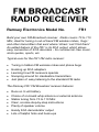
Build your own FM Broadcast receiver. Radio covers 70 to 110
Mhz, ideal for tuning in out-of-band FM wireless mikes, ‘bugs’
and other transmitters that exist where ‘others’ can’t find them!
An added feature of the FR1 is its SCA output, which allows
easy connection of SCA decoders - for commercial -free music,
stock quotes, sports, etc.
Typical uses for the FR1 FM radio receiver:
•
•
•
•
•
Tuning in hidden FM wireless mikes and phone bugs
Hooking up SCA adapters
Learning how FM receivers operate
Snooping around for clandestine transmitters
Just plain ol’ easy listening to the standard FM radio
The Ramsey FR1 FM Broadcast receiver features:
•
•
•
•
•
•
•
Runs on 9 volt battery
Choice of on-board whip antenna or external antenna
Stable tuning from 70 to 110 Mhz
Clear, concise step-by-step instructions
Plenty of speaker volume
Handy SCA demodulator output
Lots of helpful hints and hook-ups
FR-1 • 1
RAMSEY TRANSMITTER KITS
• FM100B Professional FM Stereo Transmitter
• FM25B Synthesized Stereo Transmitter
• AM1, AM25 AM Transmitters
• TV6 Television Transmitter
RAMSEY RECEIVER KITS
• FR1 FM Broadcast Receiver
• AR1 Aircraft Band Receiver
• SR2 Shortwave Receiver
• AA7 Active Antenna
• SC1 Shortwave Converter
RAMSEY HOBBY KITS
• SG7 Personal Speed Radar
• SS70A Speech Scrambler
• SP1 Speakerphone
• WCT20 Wizard Cable Tracer
• TFM3 Tri-Field Meter
• LC1 Inductance-Capacitance Meter
• WEB1 Walking Electronic Bug
• ECG1 Heart Monitor
RAMSEY AMATEUR RADIO KITS
• HR Series HF All Mode Receivers
• QRP Series HF CW Transmitters
• DDF1 Doppler Direction Finder
• CPO3 Code Practice Oscillator
• QRP Power Amplifiers
RAMSEY MINI-KITS
Many other kits are available for hobby, school, Scouts and just plain FUN. New
kits are always under development. Write or call for our free Ramsey catalog.
FR1 FM RADIO RECEIVER KIT INSTRUCTION MANUAL
Ramsey Electronics publication No. MFR1 Revision D1
COPYRIGHT 1994 by Ramsey Electronics, Inc. 590 Fishers Station Drive, Victor, New York
14564. All rights reserved. No portion of this publication may be copied or duplicated without the
written permission of Ramsey Electronics, Inc. Printed in the United States of America.
FR-1 • 2
Ramsey Publication No. MFR1
Price $5.00
KIT ASSEMBLY
AND INSTRUCTION MANUAL FOR
FR1 FM RADIO
RECEIVER KIT
TABLE OF CONTENTS
Introduction to the FR1 .................. 4
FR1 Circuit Description .................. 5
Parts List ........................................ 6
Building your kit.............................. 8
Testing and Alignment ................. 12
Troubleshooting Tips ................... 14
Other Hook-ups............................ 15
SCA output................................... 16
Schematic Diagram...................... 18
Ramsey Kit Warranty ................... 19
RAMSEY ELECTRONICS, INC.
590 Fishers Station Drive
Victor, New York 14564
Phone (585) 924-4560
Fax (585) 924-4555
www.ramseykits.com
FR-1 • 3
INTRODUCTION TO THE FR1 FM RADIO RECEIVER
Why you may ask does Ramsey sell a 'plain old FM radio' receiver? No better
person to ask than yourself! The FR1; teaches radio theory, allows you to
tune outside of the standard broadcast band (great for bugs, FM mikes and
other goodies!), has easy hook up for SCA adapters, small size and is just
plain fun.
Your receiver kit is designed to receive wideband FM transmissions typical of
standard FM broadcast stations, wireless mikes, telephone transmitters and
the like. It was not designed for Narrow Band FM transmissions (NBFM) as
you would find on police and fire transmitters, Ramsey offers a complete line
of receivers for those services.
The FR1 demonstrates a whole lot of basic radio theory in one compact,
simple circuit! Separate circuits are 'on-board' for all basic parts of a receiver,
making it easy to visualize every function. The latest in IC circuitry is used
which allows high performance without requiring exotic construction skills.
We think you'll agree that this little radio offers a lot of bang-for- the-buck, so
let's get building!
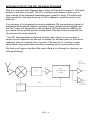
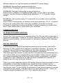
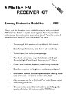
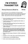
SCA
OUTPUT
U3
FL1
Q1
Q2
AFC
FM
DETECTOR
CHIP
AUDIO
OUTPUT
L.O.
FR-1 • 4
CIRCUIT DESCRIPTION
FM broadcast signals captured by the whip antenna or from the input jack are
applied to the RF amplifier Q2, a high gain, low noise microwave style
transistor. Signals are amplified about 20 dB, that's 100 times! After being
boosted, these signals are routed to the SA602 mixer-oscillator chip for
conversion down to the 10.7 Mhz Intermediate Frequency (IF). The SA602 is a
very popular chip used in a great variety of receivers from cellular telephones
to satellite receivers, in fact, here at Ramsey, we use it in every receiver kit we
sell! The reason for its popularity is that it contains most of a receivers 'front
end' circuitry on a single, easy to use chip.
Internal to the SA602 is an oscillator tuned by an external tank circuit; C11,12,
L1 and varactor diode D1. A varactor diode acts like a voltage variable
capacitor and the voltage applied across it comes from Tuning pot R12. This IF
signal is an exact reproduction of the desired signal, but at 10.7 Mhz. We then
band-pass filter it with ceramic filter FL-1. The ceramic filter allows only the
desired 10.7 Mhz signal to pass, rejecting any adjacent channel signals.
Transistor Q1 amplifies the IF signal before it is applied to the detector chip
U1.
One of the primary advantages of FM is that the program information
(modulation) is contained in carrier frequency variations and not in amplitude
changes like AM, which would be susceptible to noise and interference. This
means that we can limit or clip the signal, thus removing any noise and not
affecting the desired information. The first section of U1 performs this limiting
function, providing high gain and clipping any amplitude (noise) variations.
FM is detected in the second section using a process known as quadrature
detection. We'll not get into this too deeply because it requires a knowledge of
trigonometry identities - let's just say it extracts the frequency modulated
program information. Capacitor C1 and coil assembly L2 comprise a phase
shift network that is required by the quadrature detector. Demodulated signals
are amplified and sent out through pin 1 to the; volume control, AFC circuitry
and the SCA buffer amp. The AFC circuitry is used to properly keep the
receiver locked on to the tuned in radio station. Resistor R9 and capacitor C17
filter out any audio voltage variations so that only major frequency changes will
shift the tuning voltage to lock the frequency.
Audio signals from the volume control are amplified to speaker levels by U2,
an LM-386 audio amplifier chip. Transistor Q3 provides a buffer stage to
external SCA devices you may connect up to the FR1. SCA units decode
(demodulate, actually) 'hidden' audio and data services transmitted over
standard FM broadcast channels. These services include stock quotes, sports
scores, talk shows and even background music - commercial free!
FR-1 • 5
RAMSEY FR1 FM RADIO RECEIVER KIT PARTS LIST
CERAMIC DISC CAPACITORS:
4 .001 uf disc (marked .001 or 102 or 1 nf) [C4,5,15,27]
12 .01 uf disc (marked .01 or 103 or 10 nf) [C2,3,7,8,16,18,20,21,23,24,
28,29]
1 .1 uf disc (marked .1 or 104) [C25]
1 4.7 or 5 pf disc (marked 5 or 5K) [C1]
2 22 pf disc (marked 22) [C11,12]
2 100 pf disc (marked 100, 101, or 101K) [C6,14]
ELECTROLYTIC CAPACITORS:
4 4.7 or 10 uf [C9,17,22,26]
3 100 to 220 uf [C10,13,19]
RESISTORS AND POTENTIOMETERS:
2
1
3
1
2
1
2
5
2
10K ohm potentiometers [R12,13]
2 ohm (red-black-gold) [R19]
270 ohm (red-violet-brown) [R3,16,17]
470 ohm (yellow-violet-brown) [R6]
1K resistor (brown-black-red) [R2,18]
2.2K ohm (red-red-red) [R10]
4.7k ohm (yellow-violet-red) [R1,15]
10K resistors (brown-black-orange) [R5,7,8,9,14]
47K ohm (yellow-violet-orange) [R4,11]
INDUCTORS AND FREQUENCY COMPONENTS:
1 10.7 Mhz ceramic filter (looks like 3 leaded disc capacitor) [FL1]
1 slug tuned plastic molded coil [L1]
1 10.7 Mhz shielded can style IF transformer [L2]
SEMICONDUCTORS:
1
1
1
1
1
1
2
varactor diode, 33pf (black with green and red bands) [D1]
Zener diode, 6.2 volt (gray with black band) [D2]
SA602 IC [U3]
LM386 IC [U2]
ULN2111 IC [U1]
2SC2498 or 2SC2570A NPN transistor [Q2]
2N3904 NPN transistor [Q1,3]
FR-1 • 6
HARDWARE & MISC:
1 Printed-circuit board
1 9-volt battery hold-down bracket
1 9-volt battery connector
2 RCA-style jack (antenna connector)
1 subminiature earphone jack
1 PC mount pushbutton switch
REQUIRED, NOT SUPPLIED:
9-volt battery (alkaline or "heavy duty" type required)
Earphone, or small speaker
Antenna (whip or wire style)
OPTIONAL:
Ramsey Case, knob and whip antenna set, Model CRR1 or,
Your own choice of enclosure and hardware.
For each part, our word “install” always means these steps:
1. Pick the correct part value to start with.
2. Insert it into the correct PC board location.
3. Orient it correctly, follow the PC board drawing and the written
directions for all parts- especially when there’s a right way and a wrong
way to solder it in. (Diode bands, electrolytic capacitor polarity,
transistor shape, dotted or notched ends of IC’s, and so forth.)
4. Solder all connections unless directed otherwise. Use enough heat
and solder for clean, shiny, completed connections. Don’t be afraid of
any pen-style soldering iron having enough heat to damage a
component.
5. Trim or “nip” the excess component lead wire after soldering.
FR-1 • 7
BUILDING YOUR KIT
Check off each step as understood and completed. Examine the schematic
circuit diagram and PC-board X-ray illustration as you proceed. In all steps,
"install" means to insert the correct component in its correct PC board holes,
solder properly, and cut or "nip" away any excess wire.
Use good soldering technique - let your soldering iron tip heat each connection
wire enough so that the wire itself and the foil trace both become hot enough
together to melt the applied solder so that it flows smoothly around the wire
lead and on to the PC board trace.
1. Install J1, the RCA antenna jack. Solder all four points.
2. Install J3, the SCA output jack. Solder all four points.
3. Install J2, the speaker jack. Solder all three pins
4. Install potentiometer R12, the tuning control. Insert it into the PC board
so it seats firmly and is straight and even. Solder the three pins and the
two mounting tabs.
5. Install potentiometer R13, the Volume control in the same manner as
above.
6. Install S1, the on-off pushbutton switch. Solder all six pins firmly.
We've installed some 'landmark' parts so far just to get us used to soldering
our PC board. These parts also will give us our 'bearings' for future assembly
steps.
7. Install R10 2.2K ohm (red-red-red) directly behind R12 tuning pot.
8. Install C27, .001 uf disc capacitor (marked .001, 102, or 1nF).
9. Install C26, 4.7 or 10 uf electrolytic capacitor. Electrolytic capacitors
have polarity markings which must be observed when installing. If you look
closely at C26, you'll see a black strip on one side indicating the negative
lead, the other lead is therefore the positive. Install C26 properly as
indicated on the parts layout diagram.
10. Install jumper wire JMP1. Jumper wires act as 'bridges' for carrying
signals or power over PC traces on the board underneath. Now that you've
nipped a few leads off of some already installed components, we'll 'recycle'
a clipped lead and use it as our jumper wire! Bend the lead so it looks like
a staple, insert and solder it just like a regular component.
11. Install C15, .001 uf disc capacitor (marked .001 or 102 or 1nf).
12. Install R15, 4.7K ohm (yellow-violet-red).
FR-1 • 8
13. Install R11, 47K ohm (yellow-violet-orange).
14. Install D1, varactor diode. It has a black body with green and red bands.
Observe the correct positioning of the banded end by following the
silkscreen. The green band is positioned as shown on the silkscreen.
15. Install C17, 4.7 or 10 uf electrolytic capacitor. Observe polarity.
16. Install C14, 100 pf disc capacitor (marked 100, 101, or 101K).
17. Install slug tuned coil L1.
Time for a breather... So far we've installed all the parts necessary to tune
our receiver. D1, the varactor diode acts as the variable tuning capacitor
and the other resistors and capacitors are used to properly connect D1 to
the tuning and AFC (Automatic Frequency Control) voltages.
18. Install C19, 100 to 220 uf electrolytic capacitor. Don't forget to observe
proper polarity. C19 is a large value capacitor whose function is to 'smooth'
out any voltage fluctuations which may appear on the power supply
voltage to U3.
19. Install D2, the Zener diode. It has a gray painted glass body with a
black band. Orient the band as shown on the layout diagram. A Zener
diode acts as a voltage regulator, keeping the voltage across it constant.
This keeps frequency drift to a minimum.
20. Install C6, 100 pf disc capacitor (marked 100, 101, or 101K).
21. Install R8, 10K ohm (brown-black-orange).
22. Install R16, 270 ohm (red-violet-brown).
23. Install C11 and C12, both 22 pf disc capacitors (marked 22).
24. Install C20 .01 uf disc capacitor (marked .01 or 103 or 10 nf).
25. Install U3, the SA602 IC mixer-oscillator. The marked end of the IC
(band or dot) must face the EDGE of the PC board. If you wish, install an 8pin DIP socket, still remembering to orient and install the SA602 correctly.
PLEASE don't be afraid to solder U3 directly to the PC-board; we have seen
more repair problems with DIP sockets than from direct soldering of ICs.
26. Install C21, .01 uf disc capacitor (marked .01 or 103 or 10 nf).
27. Install R17, 270 ohm (red-violet-brown).
28. Install C4, .001 uf disc capacitor (marked .001 or 102 or 1 nf).
29. Install R5, 10K ohm (brown-black-orange)
30. Install Q2, 2SC2498 or 2SC2570A NPN transistor. Transistors are
VERY critical of correct orientation of their leads. Be sure to pay close
attention to the position of the flat side of the transistor.
FR-1 • 9
31. Install C5, .001 uf disc capacitor (marked .001 or 102 or 1 nf).
Time for another break. We've now assembled the whole 'front-end' of our
receiver. Front-end means the beginning of a receiver up to where it converts
to the IF (Intermediate Frequency).
32. Install C25, .1 uf disc capacitor (marked .1 or 104).
33. Install R19, 2 ohm (red-black-gold)
34. Install U2, the LM386 audio amplifier IC chip. The LM386 is a very
popular part, and with good reason. Tucked inside that little plastic body
are about twenty transistors that take a feeble audio signal and amplify it
up to room filling volume!
35. Install C10 and C13, both 100 to 220 uf electrolytic capacitors,
remembering to observe proper polarity of both.
36. Install C16 and C24, both .01 uf disc capacitors (marked .01 or 103 or
10 nf).
37. Install R3, 270 ohm resistor (red-violet-brown).
38. Install Jumper JMP2 using a scrap component lead.
39. Install C18, .01 uf disc capacitor (marked .01 or 103 or 10 nf).
40. Install FL1, the 10.7 Mhz ceramic IF filter. This part looks like a disc
capacitor but has three leads. Amazingly, its function is equal to a small
handful of inductors and capacitors hooked up in a bandpass filter
configuration. For those techno-types, its bandwidth is 280 KHz centered
at 10.7 Mhz with an insertion loss of only 6 dB.
41. Install Q1, a 2N3904 type. Watch placement of its flat side.
42. Install R4, 47K ohm (yellow-violet-orange)
43. Install R2, 1K ohm (brown-black-red)
44. Install C28, .01 uf disc capacitor (marked .01 or 103 or 10 nf).
45. Install jumpers JMP4 and JMP5.
46. Install Q3, 2N3904 transistor. Observe flat side orientation.
47. Install R18, 1K ohm (brown-black-red).
48. Install C22, 4.7 or 10 uf electrolytic capacitor. Watch polarity.
49. Install jumper JMP6.
50. Install resistor R6, 470 ohm (yellow-violet-brown)
51. Install C7 and C8, both .01 uf disc capacitors (marked .01 or 103 or 10
nf).
FR-1 • 10
52. Install jumper JMP3.
How about another break? Everything is done except for the demodulator section.
The front-end is bringing in the signal, the IF amp and filter are amplifying the
converted intermediate frequency signal and the audio amplifier is waiting to drive a
speaker. The only thing missing is a demodulated audio signal to amplify.
53. Install C9, 4.7 or 10 uf electrolytic capacitor. Observe polarity.
54. Install C23, .01 uf disc capacitor (marked .01 or 103 or 10 nf).
55. Install R7, 10K ohm (brown-black-orange).
56. Install R14, 10K ohm (brown-black-orange). Note that R9 is not
installed yet - we'll do that in: 'ALIGNMENT', step #9.
57. Install C2, .01 uf disc capacitor (marked .01 or 103 or 10 nf).
58. Install U1, the ULN2111 FM demodulator chip. Since this chip has 14
pins, be especially careful not to bend any pins under as you insert it into
the PC board. When you solder the chip, verify that you are soldering all
14 pins.
59. Install R1, 4.7K ohm (yellow-violet-red).
60. Install C1, 4.7 pf disc capacitor.
61. Install C3 and C29, both .01 uf disc capacitors (marked .01 or 103 or 10
nf).
62. Install L2, the shielded metal Quadrature coil. Notice that it will only go
into the PC board one way.
63. Install the 9 volt battery clamp. Use a scrap component lead wire looped
through the holes in the clamp and into the holes in the PC board. Solder the
wire to the clamp but don't use too much solder as this will prevent you from
seating the battery fully into the clamp.
64. Install the 9 volt battery snap connector. Make sure you put the right
color wire into the proper hole on the PC board.
Hey, all done and ready to listen to tunes from our radio... Well, at least we're
ready to test and align it - then we'll listen to our tunes!
FR-1 • 11
TESTING AND ALIGNMENT
A Hex head alignment tool is required to tune up your FR1. If you do not
already have a set of plastic or nylon coil alignment tools and expect to build
other radio or transmitter type kits, such tools are well worth having and can be
found at any electronics store, including Radio Shack. While a hex style Allen
wrench will fit the coil slug, the metal itself will drastically change the coil's
inductance while it is in the slug. For this reason you should not use an Allen
wrench unless you don't mind the trial and error process of; turning the slug,
withdrawing the tool, checking tuning, reinserting the tool, retuning, checking
and so on.
You can fabricate your own non-metallic tuning tool with some patience, a bit of
sandpaper and a piece of plastic rod or wood stick. Try a large wooden
matchstick, kabob skewer, or small plastic crochet needle. Carefully sand down
the end to a hex shaped form and check for proper fit within the coil slug. It is
better to have the tool fit loosely rather than too tight, since a tight tool will cause
stress on the delicate slug.
1. Connect the following:
Fresh 9 volt battery (preferably heavy duty alkaline type)
Speaker or earphone
A short length of wire (about two feet) to serve as antenna or
The telescopic whip if the optional matching case and knob set was
purchased.
2. Set the Volume and the Tune controls to the center of their range.
3. Press the power switch 'ON', you should hear some rushing noise from your
speaker.
4. Rotate the volume control and see if it does its job.
5. Slowly turn L2's slug back and forth for maximum noise. This noise should be
similar to what you would hear when a regular FM radio is tuned between
stations. L2 may be tuned with a regular blade style screwdriver.
6. Try turning the Tune control. See if you can receive any stations, but don't be
alarmed if nothing is received since we haven't adjusted the oscillator coil yet.
7. The oscillator coil, L1 is adjustable to receive from 70 to 110 Mhz. We have to
adjust it to cover the frequency range of interest. For alignment purposes we'll
work with the understanding that the standard FM 88-108 Mhz band is what we
wish to receive.
FR-1 • 12
8. Using your alignment tool, slowly rotate L1's slug gently so that the slug is
even with the top of the coil form. (Do not force the slug; if it binds, rotate the
slug back and gently 'rock it' to-and-fro as you would a thread forming tap.
Slugs are by nature very brittle and will crack easily). Now carefully rotate the
slug into the coil form seven turns. The slug will be in about 1/4 of an inch.
Rotate the tune control until you hear an FM broadcast signal. Adjust L2 for
best sound.
9. Install R9, 10K ohm (brown,black,orange). R9 adds in AFC voltage to
stabilize against drift. Without it your radio may ‘wander’.
10. After a signal is received, rotate the tune control to receive other stations. If
the stations seem to ‘jump away’ as you try to tune one in, the coil L1 is
adjusted incorrectly and should be retuned. The reason for this odd
phenomenon is that the AFC circuit is pushing the signal away rather than
pulling it in. This is caused by having the oscillator 10.7 Mhz below the desired
signal rather than 10.7 Mhz above it. A similar example of this is closing your
eyes, hearing a sound, but not being able to determine if it is in front of, or
behind you. Readjusting L1 will correct this situation. Make sure the slug is
about three turns from the top of the coil form.
11. Calibrating the receiver is easy:
a. Tune in a station known to operate at the low end (88 Mhz) of the
FM broadcast band.
b. Rotate the tune control almost fully counter-clockwise to where
that station should logically be located on the dial.
c. Turn L1's slug until that same station is received. The tune
control should now tune in the entire FM broadcast band.
RECEIVER SENSITIVITY
Your FR1 FM receiver will exhibit sensitivity equal to most standard radio
receivers. For the ultimate in sensitivity when using an external antenna, our
SA7 broadband preamp is an ideal choice. Or, our AA-7 Active Antenna
interfaces extremely well, boasts both an internal telescopic whip, external
antenna jack and even a matching case!
OUT-OF-BAND OPERATION
Although many folks use their FR1 for comfortable FM broadcast reception,
some James Bond types will want to use it to receive clandestine transmissions
from phone bugs, room transmitters and the like. It’s a simple matter to retune
coil L1 to receive the frequency band of interest; however, we ask that you first
verify that your FR1 receives the FM broadcast band correctly before retuning.
FR-1 • 13
SPEAKER SELECTION
A fifty-cent' speaker, lying naked on your workbench will not give you a fair test
of your FR1 audio quality or volume. Speaker quality and well-designed
enclosures have their clear purposes! A reasonable speaker in a box delivers a
pleasant listening volume as well as significantly improved fidelity.
ADDING A POWER-ON INDICATOR
Adding a simple LED power-on indicator to your Ramsey kit receiver is easy.
All you need is the LED itself and a small 1K ohm resistor. Study the PC-traces
between the positive battery supply wire and the on-off switch. The unused
connectors on top of your switch are an ideal point to get the + DC voltage
needed for the anode (longer lead) of the LED.
Plan where and how you wish to install the LED in your enclosure. Locating the
LED immediately above the on-off switch is logical and ideal. The simplest way
to make a neat installation is to drill a hole just slightly smaller than the
diameter of the LED. Then, enlarge the hole a little bit at a time, just enough to
let the LED be pressed in and held firmly. The resistor may be connected to
either the anode or cathode of the LED, but the anode side MUST go to + DC,
with the cathode connected to the nearest common ground point.
If you are wondering why we did not include these pennies worth of parts with
your kit, you can believe any of the following reasons: (1) We wanted to stretch
your battery budget: drawing about 15 ma., how long will your battery last if you
leave you receiver on for a few days, just like we leave our computers, ham
radios or accessories on all the time? (2) We thought you'd have more fun
planning and installing you own lamp that glows in the dark! (3) We couldn’t
decide which color you would like best.
TROUBLESHOOTING TIPS:
PROBLEM: ALL signals are hard to tune, unstable, 'jumps away'.
SOLUTION: The oscillator is tuned on the wrong side (10.7 Mhz BELOW
rather than above) of the desired receive frequency. Retune coil L1. Also this
condition could be caused by a weak battery! Use a fresh alkaline cell. Any
strong signal forces the audio circuit to rob voltage from the oscillator, which
causes the instability.
PROBLEM: Occasionally good but erratic operation.
SOLUTION: Check very carefully for poor solder connections.
PROBLEM: Loud AC hum or buzz.
SOLUTION: . If you are using a 9-volt AC power adapter, the adapter design
may not be of sufficient quality for this application. Try bypass capacitors, a
FR-1 • 14
different adapter or a well designed and filtered DC power supply.
PROBLEM: Signals have unpleasant distortion.
SOLUTION: Quadrature coil L2 is not adjusted properly.
PROBLEM: Oscillator inoperative or wrong frequency.
SOLUTION: In addition to checking solder joints, be sure that L1 is tuned
correctly, and the frequency determining capacitors, C11,12 are the correct
values.
PROBLEM: Unit receives when L1 is adjusted, but not able to be tuned with
Tune control.
SOLUTION: Check position of varactor diode and capacitors; C6,14. A careful
check of all construction WILL solve your problem. Over 95% of the kits
returned for repair have nothing more than a simple assembly or construction
error! Have another pair of eyes check your work first.
OTHER HOOK-UPS:
ALTERNATE POWER SOURCES
Most of the FR1 circuitry can be operated from 6 to 14 volts without damage or
significant modification. However, it is quite important that you carefully hook up
with the correct polarity - reverse polarity or excessive voltages WILL damage
your kit.
DIGITAL READOUT
A novel hook-up is to add a general purpose frequency counter such as the
Ramsey CT-90 to give a direct readout of oscillator frequency. Of course, we
know that the oscillator is not oscillating at the same frequency that we're
receiving - it's actually 10.7 Mhz above the dialed in frequency.
This may seem like overkill, but we mention it to point out the possibilities that a
low cost kit offers you in experimenting and just plain 'fooling around'! And we
don't mind suggesting that a Ramsey counter makes an attractive, matching
companion to your Ramsey kit as well as being a valuable tool with lots of
practical uses for any electronic hobbyist.
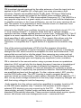
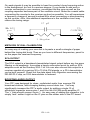
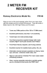
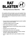
While you could experiment with an RF pickup loop or tuned circuit and counter
preamplifier to boost the oscillator's tiny output to a level suitable for the
counter, the most reliable method is to wire a high-impedance counter probe
line directly to pin 7 of the SA602, terminated to a rear-panel frequency counter
connector of your choice. This will consist of a short piece of mini - coax to a 1
megohm resistor bridged by a 27 or 33 pf capacitor as shown:
FR-1 • 15
On weak signals it may be possible to hear the counter's busy humming action
in the background, but not to a serious degree. If you decide to add such a
counter connection to your receiver, remember that the coax as well as the
coupling capacitor becomes part of the oscillator circuit. Make the coaxial cable
connecting the counter to the receiver as short as possible. You will experience
a frequency change of several hundred KHz when connecting or disconnecting
up the counter. Also, this additional capacitance in the oscillator circuit may
reduce the tuning range.
27 pF
NE
SA 602
pin 7
TO
COUNTER
1 Megohm
METHODS OF DIAL CALIBRATION
An easy way of making your own dial is to paste a small rectangle of paper
behind the tuning dial knob. Then as you tune in different frequencies, pencil in
on the paper the received frequency.
SCA OUTPUT
The SCA output is a baseband demodulated signal output before any low pass
filtering or de-emphasis. It provides a handy connection point for add-on SCA
adapters such as the Ramsey SCA-1 kit.You can also connect this output to a
receiver capable of receiving 30 to 75 KHz FM signals, or a PLL demodulator
you've built yourself. Check out the data sheet from Signetics concerning the
NE-565 PLL chip, an SCA demodulator is featured.
BOOSTING AUDIO OUTPUT
Your FR1 was designed for clean, undistorted audio from average FM
broadcast stations, while keeping battery current drain low. You may
significantly increase the FR1’s audio output by adding a single 10 uf
electrolytic capacitor across pins 1 and 8 on the LM-386 audio amplifier IC.
The ‘+’ side should connect to pin 1. An easy way of adding this capacitor is to
simply ‘tack’ solder it right on the IC pins on the solder side of the PC board.
FR-1 • 16
IN CLOSING...
Finally, we remind you that modifications of the kit put you on your own, voiding
your Ramsey limited warranty, making your unit ineligible for factory repair.
Make sure the receiver is working properly and that you understand how to use
and repair it BEFORE making any changes in the original design. If you’ve
enjoyed building this Ramsey kit, there are plenty more! Our nifty FM25B
Stereo FM Transmitter is especially popular. Ask for our free catalog - kit
building’s a blast!
FR-1 • 17
FR-1 • 18
The Ramsey Kit Warranty
Please read carefully BEFORE calling or writing in about your kit. Most problems can be
solved without contacting the factory.
Notice that this is not a "fine print" warranty. We want you to understand your rights and ours too! All
Ramsey kits will work if assembled properly. The very fact that your kit includes this new manual is
your assurance that a team of knowledgeable people have field-tested several "copies" of this kit
straight from the Ramsey Inventory. If you need help, please read through your manual carefully, all
information required to properly build and test your kit is contained within the pages!
1. DEFECTIVE PARTS: It's always easy to blame a part for a problem in your kit, Before you conclude
that a part may be bad, thoroughly check your work. Today's semiconductors and passive components
have reached incredibly high reliability levels, and it’s sad to say that our human construction skills
have not! But on rare occasions a sour component can slip through. All our kit parts carry the Ramsey
Electronics Warranty that they are free from defects for a full ninety (90) days from the date of
purchase. Defective parts will be replaced promptly at our expense. If you suspect any part to be
defective, please mail it to our factory for testing and replacement. Please send only the defective part
(s), not the entire kit. The part(s) MUST be returned to us in suitable condition for testing. Please be
aware that testing can usually determine if the part was truly defective or damaged by assembly or
usage. Don't be afraid of telling us that you 'blew-it', we're all human and in most cases, replacement
parts are very reasonably priced.
2. MISSING PARTS: Before assuming a part value is incorrect, check the parts listing carefully to see
if it is a critical value such as a specific coil or IC, or whether a RANGE of values is suitable (such as
"100 to 500 uF"). Often times, common sense will solve a mysterious missing part problem. If you're
missing five 10K ohm resistors and received five extra 1K resistors, you can pretty much be assured
that the '1K ohm' resistors are actually the 'missing' 10 K parts ("Hum-m-m, I guess the 'red' band
really does look orange!") Ramsey Electronics project kits are packed with pride in the USA. If you
believe we packed an incorrect part or omitted a part clearly indicated in your assembly manual as
supplied with the basic kit by Ramsey, please write or call us with information on the part you need
and proof of kit purchase
3. FACTORY REPAIR OF ASSEMBLED KITS:
To qualify for Ramsey Electronics factory repair, kits MUST:
1. NOT be assembled with acid core solder or flux.
2. NOT be modified in any manner.
3. BE returned in fully-assembled form, not partially assembled.
4. BE accompanied by the proper repair fee. No repair will be undertaken until we have received the
MINIMUM repair fee (1/2 hour labor) of $25.00, or authorization to charge it to your credit card
account.
5. INCLUDE a description of the problem and legible return address. DO NOT send a separate letter;
include all correspondence with the unit. Please do not include your own hardware such as
non-Ramsey cabinets, knobs, cables, external battery packs and the like. Ramsey
Electronics, Inc., reserves the right to refuse repair on ANY item in which we find excessive
problems or damage due to construction methods. To assist customers in such situations,
Ramsey Electronics, Inc., reserves the right to solve their needs on a case-by-case basis.
The repair is $50.00 per hour, regardless of the cost of the kit. Please understand that our technicians
are not volunteers and that set-up, testing, diagnosis, repair and repacking and paperwork can take
nearly an hour of paid employee time on even a simple kit. Of course, if we find that a part was
defective in manufacture, there will be no charge to repair your kit (But please realize that our
technicians know the difference between a defective part and parts burned out or damaged through
improper use or assembly).
4. REFUNDS: You are given ten (10) days to examine our products. If you are not satisfied, you may
return your unassembled kit with all the parts and instructions and proof of purchase to the factory for
a full refund. The return package should be packed securely. Insurance is recommended. Please do
not cause needless delays, read all information carefully.
FR-1 • 19
FR1 FM BROADCAST RECEIVER
Quick Reference Page Guide
Introduction to the FR1 ...................4
FR1 Circuit Description ...................5
Parts List .........................................6
Building your kit ..............................8
Testing and Alignment ..................12
Troubleshooting Tips ....................14
Other Hook-ups ............................15
SCA output ...................................16
Schematic Diagram ......................18
Ramsey Kit Warranty ....................19
REQUIRED TOOLS
• Soldering Iron Ramsey WLC100
• Thin Rosin Core Solder Ramsey RTS12
• Needle Nose Pliers Ramsey MPP4 or RTS05
• Small Diagonal Cutters Ramsey RTS04
<OR> Technician’s Tool Kit TK405
ADDITIONAL SUGGESTED ITEMS
• Holder for PC Board/Parts Ramsey HH3
• Desoldering Braid Ramsey RTS08
• Digital Multimeter Ramsey M133
Price: $5.00
Ramsey Publication No. MFR1
Assembly and Instruction manual for:
RAMSEY MODEL NO. FR1 FM BROADCAST
RADIO RECEIVER KIT
RAMSEY ELECTRONICS, INC.
590 Fishers Station Drive
Victor, New York 14564
Phone
(585) 924-4560
Fax
(585) 924-4555
www.ramseykits.com
FR-1 • 20
TOTAL SOLDER POINTS
202
ESTIMATED ASSEMBLY
TIME
Beginner............... 6 hrs
Intermediate ......... 3.4 hrs
Advanced ............. 2.6 hrs
This Quality Electronics
Kit was designed and
packed in the USA