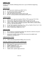
1
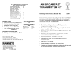
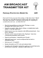
AM BROADCAST
TRANSMITTER KIT
Ramsey Electronics Model No.
AM1
Ever want to be your own disc jockey or talk show host ? Build
and run your own AM broadcast station with this exciting kit !
The AM1 transmitter is designed specifically for simplicity of
construction and use - an ideal first kit !
•
Great for transmitting your tape deck, CD player, or voice
throughout the house, yard, or car !
•
Powerful enough for high school, college, or neighborhood radio
station - in use the world over !
•
Easily tunes to any clear channel on the AM broadcast band. - from
530 to 1750 KHz.
•
Operates on the same principle as the “big-boys”, learn how
commercial transmitters work as well !
•
Superior performance - transmits up to 1/4 mile !
•
Adjustable input level - can be configured for line level or
microphone input.
•
Unit runs on 9 - 12 volts DC.
•
Handy information on FCC rules and antenna hints.
•
Complete and informative instructions guide you to a kit that works
the first time, every time - enhances resale value, too !
AM1 • 1
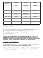
PARTIAL LIST OF AVAILABLE KITS
RAMSEY TRANSMITTER KITS
• FM10A FM Stereo Transmitter
• MP3FM Synthesized MP3 Transmitter
• FM25B, FM100B Synthesized FM
Stereo Transmitters
• AM25 Synthesized AM Transmitter
• AM1 AM Transmitter
RAMSEY RECEIVER KITS
• FR1 FM Broadcast Receiver
• AR1 Aircraft Band Receiver
• AA7 Active Antenna
• SC1 Shortwave Converter
RAMSEY HOBBY KITS
• SG7 Personal Speed Radar
• SS70 Speech Scrambler
• TT1 Telephone Recorder
• SP1 Speakerphone
• MD3 Microwave Motion Detector
• PH10 Peak hold Meter
• LC1 Inductance-Capacitance Meter
RAMSEY AMATEUR RADIO KITS
• HR Series HF All Mode Receivers
• QRP Series HF CW Transmitters
• CW7 CW Keyer
• CPO3 Code Practice Oscillator
• QRP Power Amplifiers
RAMSEY MINI-KITS
Many other kits are available for hobby, school, scouts and just plain FUN. New
kits are always under development. Write or call for our free Ramsey catalog.
AM1 AM BROADCAST TRANSMITTER KIT INSTRUCTION MANUAL
Ramsey Electronics publication No. MAM1 Revision 1.2 First printing: August, 1994
COPYRIGHT 1994 by Ramsey Electronics, Inc. Fishers Station Drive, Victor, New York
14564. All rights reserved. No portion of this publication may be copied or duplicated without the
written permission of Ramsey Electronics, Inc. Printed in the United States of America.
AM1 • 2
Ramsey Publication No. MAM1
Manual Price Only $5.00
KIT ASSEMBLY
AND INSTRUCTION MANUAL FOR
AM BROADCAST
TRANSMITTER AM1
TABLE OF CONTENTS
Introduction to the AM1 ................. 4
AM1 Circuit Description ................ 4
Schematic Diagram....................... 6
Parts Layout Diagram ................... 7
Parts List ........................................ 8
Assembly Instructions ................... 9
Antenna Considerations............... 13
Alignment Procedures.................. 14
Experimental Broadcasting .......... 14
Troubleshooting ........................... 15
FCC Information........................... 16
Antenna Experimenting................ 18
Ramsey Kit Warranty ................... 19
RAMSEY ELECTRONICS, INC.
590 Fishers Station Drive
Victor, New York 14564
Phone (585) 924-4560
Fax (585) 924-4555
www.ramseykits.com
AM1 • 3
INTRODUCTION
Many times we wish to be heard via wireless communications. Whether
transmitting music or voice, what’s required is a stable transmitter tunable to
an unused frequency on the broadcast band. Here at Ramsey, we have
produced several models of FM wireless units for years. Recent requests for
an AM type transmitter have been answered with this kit.
The Ramsey AM1 transmitter is a true broadcast transmitter, which any
person may build and use in accordance with the rules of one’s national
telecommunications authority. For U.S. residents, that authority is the
Federal Communications Commission (FCC). The AM1’s low power
broadcasting capabilities make it practical for many uses, but one should
remember that this transmitter is definitely not a toy. We will refer to the FCC
regulations frequently in this manual and provide you with some information
necessary to enjoy the AM1’s capabilities in accordance with the law.
•
•
•
•
Typical uses for the AM1 include:
Student operated school radio stations.
Re-broadcasting received audio for shortwave or HAM radio use.
Listening aid for auditoriums, churches, or other events.
Short range experimentation.
We think that you will be very pleased with the transmitting range, audio
quality, and frequency stability of this build it yourself AM transmitter. If you
follow our assembly instructions carefully and use your AM1 in accordance
with applicable FCC rules, a whole new world of sharing news, views, and
music with friends and neighbors awaits you.
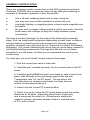
AM1 CIRCUIT DESCRIPTION
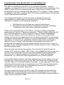
Before we dive into the circuit description of the AM transmitter, first we’ll
describe exactly what we mean when we say “AM”. An (A)mplitude (M)
odulated signal is actually a combination of two signals. The high frequency
carrier is the frequency that one will tune on the radio receiver’s dial, from
530 to 1750 KHz. The modulation is the audio information that rides “on top”
of the high frequency carrier, resulting in a changing of the level, or
amplitude, of the output waveform. Take a glance at the schematic and
follow along at how we produce this AM waveform.
The RF oscillator consists of Q6 and associated components. The
frequency of operation is determined by selecting the proper values for C9
and C10, and adjusting the inductance of coil L2. The “buffer” amplifier (Q5)
is connected to the base of Q6 in order to use the undistorted oscillator
AM1 • 4
Low Freq uenc y Audio Wa ve form
High Freq ue ncy Radio Carrier
Amplitude Mod ulated Signal
output for the RF carrier frequency.
The audio input path is routed from J1, the audio input source, to transistor Q2
to amplify the incoming signal. Notice that the transistor is biased to be linear
using resistors R3, R5, and R6. The incoming audio signal is therefore
amplified undistorted (for great sounding audio). Optional capacitor C4 is used
only when a microphone input is used to provide additional gain from transistor
Q2. The audio input level to the amplifier can also be adjusted using R12, the
input level adjustment.
The resulting audio output is fed to transistor Q1, which does not provide any
gain, but supplies enough current to modulate the RF carrier. Inductor L1
allows the low frequency audio to pass through but “chokes” the RF signal and
does not allow it to get “back into” the audio circuitry.
Transistors Q3 and Q4 comprise the “power amplifier” section of the circuit.
Their collector supply voltage is furnished by Q1, thus producing an AM output
waveform. This signal is then low pass filtered using C13, C14, and L3.
Notice also that the audio information is applied at the power amplifier stage.
This is referred to as “high level” modulation, and is commonly used for high
power AM broadcast stations. The distinct advantage to this is that the RF
amplifiers need not be biased for linear operation. It is much cheaper to
manufacture a linear amplifier for the relatively low frequency audio, than to
produce the AM waveform at a low level and amplify it to a higher power level
without distortion. The main disadvantage of high level modulation is that the
audio modulator’s power must be half that of the final transmitter, not too tough
for our low power kit, but try to imagine the amplifier for a 50,000 watt AM
broadcast station! Boy, that audio amp would sure crank the ‘ol car stereo!
It should also be stated that, due to the linear operation of the amplifiers in this
circuit (transistors Q1 and Q2 biased “on”), this circuit will consume some
power. It is not recommended that a common rectangular 9V battery be used
to power this kit. Instead, a battery “pack” consisting of eight 1.5 volt cells, a
12V sealed battery, or other external 12V DC supply may be used.
AM1 • 5
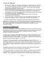
AM1 • 6
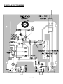
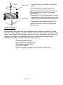
PARTS LAYOUT DIAGRAM
AM1 • 7
PARTS LIST
Please verify that the following items are in your kit before beginning
assembly.
RESISTORS
4
2
1
4
1
270 ohm [red-violet-brown] (R6,7,9,11)
1K ohm [brown-black-red] (R5,10)
2.2K ohm [red-red-red] (R1)
10K ohm [brown-black-orange] (R2,3,4,8)
5K PC mount potentiometer [marked 502] (R12)
CAPACITORS
1
1
1
4
7
3
1
220 pF disc capacitor [marked 220 or 221] (see text C9,10,16)
470 pF disc capacitor [marked 470] (see text C9,10,16)
.001 µF disc capacitor [marked .001 or 102] (see text C9,10,16)
.002 or .0022 µF disc capacitor [marked .002,.0022 or 2000,2200]
(C13,14, see text C9,10,16)
.01 µF disc capacitor [marked .01 or 103 or 10nF] (C3,5,6,7,8,11,12)
10 µF electrolytic capacitors (C1,2,4)
220 µF electrolytic capacitor (C15)
INDUCTORS
1
1
1
48 µH inductor [enameled copper wire wound on ferrite core] (L1)
10 µH inductor [marked 100] (L3)
slug tuned variable inductor [fine wire wound on plastic and
cardboard cylinder] (L2)
SEMICONDUCTORS
6
NPN transistors [marked 3904] (Q1,2,3,4,5,6)
MISCELLANEOUS PARTS AND HARDWARE
2
1
1
1
1
RCA type PC mount connectors (J1,2)
2.5mm power jack (J3)
DPDT pushbutton switch (S1)
AM1 printed circuit board
“diddle stick” plastic alignment tool
AM1 • 8
ASSEMBLY INSTRUCTIONS
There are numerous solder connections on the AM1 printed circuit board.
Therefore, PLEASE take us seriously when we say that good soldering is
essential to the proper operation of your transmitter!
•
•
•
•
Use a 25-watt soldering pencil with a clean, sharp tip.
Use only rosin-core solder intended for electronics use.
Use bright lighting, a magnifying lamp or bench-style magnifier may
be helpful.
Do your work in stages, taking breaks to check your work. Carefully
brush away wire cuttings so they don't lodge between solder
connections.
We have a two-fold "strategy" for the order of the following kit assembly
steps. First, we install parts in physical relationship to each other, so there's
minimal chance of inserting wires into wrong holes. Second, whenever
possible, we install in an order that fits our "Learn-As-You Build" Kit building
philosophy. This entails describing the circuit that you are building, instead of
just blindly installing components. We hope that this will not only make
assembly of our kits easier, but help you to understand the circuit you’re
constructing.
For each part, our word "Install" always means these steps:
1. Pick the correct part value to start with.
2. Insert the part, oriented correctly, into its correct holes in the PCboard.
2. If helpful, gently BEND the part's wire leads or tabs to hold it into
place, with the body of the part snugly against the top side
("component side") of the PC-board. The top side is the
side that does not contain metal traces, but does have an
outline of each part printed on it.
3. Insert it into the correct PC board location.
4. Orient it correctly, follow the PC board drawing and the written
directions for all parts - especially when there's a right way
and a wrong way to solder it in. (Diode bands, electrolytic
capacitor polarity, transistor shapes, dotted or notched ends
of IC's, and so forth.)
AM1 • 9
5. Solder all connections unless directed otherwise. Use enough
heat and solder flow for clean, shiny, completed connections.
6. Trim or nip all excess wires extending beyond each solder
connection, taking care that wire trimmings do not become lodged in
PC-board solder connections.
Now, let's get building!
Since you may appreciate some “warm-up” soldering practice as well as a
chance to put some “landmarks” on the PC board, we’ll first install some
“hardware” components. This will also help us to get acquainted with the up down, left - right orientation of the circuit board. Remember that the
components will be mounted on the “component” (printed) side of the circuit
board and then soldered on the “solder” (foil) side of the circuit board.
1. Install DPDT switch S1. Position it so that the plunger of the switch
extends over the edge of the PC board. Be sure to push the switch flat
to the circuit board. Solder all six connections.
2. Install RCA phono jacks J1 and J2. These connectors will “snap” into
place before soldering. Don’t be afraid to completely solder all three
ground connections as these will also limit the “stress” on the input and
antenna connections.
3. Install the 2.5 mm power connector in the J3 position.
We’ll now begin to construct the RF oscillator section of the AM1. Be sure to
mount the components as close as possible to the PC board to avoid
“radiating” any unwanted signals due to long lead lengths.
4. Install L2, the slug tuned inductor. Solder all three tabs.
5. Install C8, .01 µF disc capacitor [marked .01 or 103 or 10nF].
6. Install R8, 10K ohm [brown-black-orange].
7. Install C6, .01 µF disc capacitor [marked .01 or 103 or 10nF].
8. Identify Q6, a 2N3904 NPN transistor. When installing Q6, observe
correct placement of the flat side. Press the transistor snugly into the PC
board so that only a minimum amount of wire lead is exposed above the
board. In soldering, do not be afraid of using enough heat to make a
good solid connection.
9. Install R11, 270 ohm [red-violet-brown].
10. Install R7, another 270 ohm [red-violet-brown].
AM1 • 10
11. Install Q5, a 2N3904 transistor. Be sure to orient it correctly! See the
parts diagram for correct orientation.
12. Install C7, .01 µF disc capacitor [marked .01 or 103 or 10nF].
13. Install R9, 270 ohm [red-violet-brown].
14. Install C15, 220 µF electrolytic capacitor. Electrolytic capacitors are
polarized with a (+) and a (-) lead and must be installed in the correct
orientation. Ordinarily, only the negative side is marked on the capacitor
body with a dark band and the (-) sign clearly shown, while PC boards
will usually show the (+) hole location. Use care to ensure proper
polarity.
Whew! Now that wasn’t so bad was it? You have just completed most of the
oscillator. Notice that we have excluded a few capacitors, C9, 10, and 16.
We will install these later while testing the unit. Take a moment now to
recheck your work for clean, shiny solder connections. Resolder any
connections that are less than perfect.
We’ll get back to building now, starting at the audio input and working
through the audio circuitry.
15. Install trimmer potentiometer R12. Solder all three leads.
16. Install C2, 10 µF electrolytic capacitor. Be sure to orient the part
correctly. See the parts placement diagram for correct orientation.
17. Install R5, 1K ohm [brown-black-red].
18. Install C12, .01 µF disc capacitor. This capacitor act as a RF bypass
component. It effectively “shorts” the high frequency signals to ground
while not effecting the low frequency audio.
19. Install Q2, 2N3904 NPN transistor [marked 2N3904]. Pay attention to
the orientation!
20. Install R3, 10K ohm [brown-black-orange].
21. Install R1, 2.2K ohm [red-red-red].
22. Install R2, 10K ohm [brown-black-orange].
23. Install R6, 270 ohm [red-violet-brown].
24. Install C1, 10 µF electrolytic capacitor. Watch the polarity!
25. Install R4, 10 K ohm [what colors were those ??!!] [brown-blackorange].
26. Install C11, .01 µF disc capacitor [marked .01 or 103 or 10nF].
AM1 • 11
27. Install C3, .01 µF disc capacitor.
28. Install Q1, 2N3904 NPN transistor. Be sure to orient the part
correctly.
You’ve just completed the audio input circuitry. Have another look at your
solder connections to ensure that there are no cold or intermittent joints.
Hang in there, only 7 parts to go!
29. Install L1, the large 48 µH wire wound inductor.
30. Install R10, 1K ohm resistor [brown-black-red].
31. Install Q3 and Q4, the last two 2N3904 NPN transistors. Be sure to
orient the flat side correctly.
32. Install C5, .01 µF disc capacitor [marked .01 or 103 or 10nF].
33. Install C13, .002 or .0022uF disc capacitor [marked 2000, 2200
or .002, .0022].
34. Install inductor L3, 10 µH [marked 100].
35. Install C14, .002 or .0022uF disc capacitor [marked 2000, 2200
or .002, .0022].
What about those extra parts !!!??? Now you’ll need to make some
decisions on how we are going to use our AM transmitter. Follow the
following final assembly instructions carefully.
AM1 Final Assembly Instructions
If you wish to use a microphone as the audio source for your AM
transmitter, you’ll need to increase the gain of the audio amplifier by
installing electrolytic capacitor C4.
If the input is to be “line level” audio from a tape or CD player, there is no
need to install capacitor C4.
If necessary, (as discussed above) install 10 µF electrolytic capacitor C4.
Observe the correct polarity!
Next, you’ll need to determine what frequency you wish to set your
transmitter to. It really is not sufficient to just “check” the AM band for an
empty frequency, using the AM radio closest at hand. It is your responsibility
to research what AM stations can be listened to in your area and not to
interfere with any of your neighbors in their reception of any commercially
licensed broadcast station. Usually a modern car radio (with external
AM1 • 12
Transmitter
Frequency (KHz)
C9 (pF)
C10 (pF)
C16 (pF)
1000
(marked .001 or 102)
2000/2200
(marked .002/.0022)
2000/2200
(marked .002/.0022)
550 - 720
2000/2200
(marked .002/.0022)
2000/2200
(marked .002/.0022)
Not used
700 - 870
1000
(marked .001 or 102)
2000/2200
(marked .002/.0022)
Not used
800 - 1000
470
(marked 470)
2000/2200
(marked .002/.0022)
Not used
1000 - 1250
470
(marked 470)
1000
(marked .001 or 102)
Not used
1250 - 1600
220
(marked 220)
1000
(marked .001 or 102)
Not used
1500 - 1750
220
(marked 220)
470
(marked 470)
not used
520 - 660
antenna) is extremely sensitive and a good indicator of what stations will be
received in your area.
Once your have determined what your operating frequency will be, refer to
the following chart for the correct values of C9, C10 , and C16.
Install the correct values for C9, C10, and C16.
CONGRATULATIONS
You have just completed your AM1 wireless broadcast unit. Take a well
deserved break now. Give your eyes a rest. When you return, be sure to
check over your work on the entire circuit board. Energizing the circuit board
with solder “bridges” or misplaced components can damage your kit.
ANTENNA CONSIDERATIONS
For many applications, a 5 - 6 foot wire antenna connected to the center pin
of the “RF OUT” connector will produce satisfactory results.
Another simple but effective hint is to connect the chassis “ground” to a good
earth ground (like a cold water pipe, etc.). Be sure, however, that the total
length of the antenna, feedline, and grounding wire is less than 10 feet as
required by the FCC Part 15 rules.
AM1 • 13
Once the tuning capacitors and some sort of antenna have been installed,
it’s time to align your transmitter.
ALIGNMENT PROCEDURES
Keep all tests very brief until you have carefully chosen an open operating
frequency in the AM broadcast band.
1. Tune an AM receiver to a quiet spot on the dial where you wish to
receive your transmitter.
2. Connect an antenna to the RF OUT jack.
3. Energize the circuit with a suitable power source.
4. Using the plastic tuning tool, adjust coil L2 until you hear the AM1’s
carrier signal. If the radio is very close and you have configured the AM1
for a mike input, you may hear a feedback squeal. It might seem a little
tricky at first to set the exact frequency you want, as the frequency may
be affected by how close your hand is to the circuit board.
5. Rotate the LEVEL ADJ control to its full clockwise position. This is the
maximum level input position. The best audio source for testing if you’ve
configured the AM1 for line level is the line level outputs of a tape deck
or CD player. Most stereo systems have a variety of output jacks of
which one or more are “line level”. Connect the audio source to the
AUDIO IN jack . Adjust R12 for undistorted audio.
EXPERIMENTAL “BROADCASTING” PROJECTS
To use the AM1 successfully as a “broadcasting” service to interested
listeners in a school or immediate neighborhood, most of your effort will be
concentrated on smoothly “managing” or mixing the audio signals into the
transmitter input. Operation of the transmitter consists of the following:
If you wish to “mix” between audio inputs, i.e. microphone and music
sources, you may need an external audio “mixer” unit. Many sources exist
for audio mixers, including the Radio Shack No. 32 - 1105 which is one of
least expensive that we have found. There are more sophisticated models,
but bear in mind that model numbers and specs for such units can change
from year to year. Also, some home entertainment audio equipment includes
simple mixing capabilities which will permit you to fade and “cue” music and
microphone inputs.
AM1 • 14
TROUBLESHOOTING INSTRUCTIONS
While we had hoped that it wouldn’t come to this, if you are having trouble with
your transmitter, here are a few suggestions.
By far the most common sources of problems are misplaced parts or poor
solder connections. It’s always best to take a break before searching for bad
connections. Around here it’s referred to as the “Irwin Time Test” which states
that “anything left alone long enough seems to repair itself !” A good way of
checking component placement is to double check the assembly steps going
backwards from the last steps to the the first. Bright lighting and a magnifying
aid can be helpful in identifying soldering problems.
Use a methodical, logical troubleshooting technique. Most problems can be
solved using common sense. A volt-ohm meter and a clear head are usually
all that are needed to correct any problem. Please understand that it is nearly
impossible to “troubleshoot” by phone, any specific questions should be
documented and sent to us by mail.
AM1 • 15
PLEASE READ THIS IMPORTANT FCC INFORMATION
The AM1 is classified by the FCC as an “intentional radiator,” and it’s
operation is covered by Part 15 of the FCC rules which were updated in June
1989. In brief, what you need to know about these rules is that your AM
broadcaster must not interfere with AM radio or TV reception of other people.
As designed, the AM1 complies with FCC technical requirements for devices
used in the AM broadcast band.
The individual kit builder and all end users of this device assume
responsibility for lawful uses conforming to the FCC part,15 rules.
Operation is subject to the following conditions:
1. This device may not cause any harmful interference
2. This device must accept any interference received, including
interference that may cause undesired operation.
These rules are published in 100 “Parts,” covering anything imaginable
concerning the topic of “Telecommunications.” The six books containing the
FCC rules are section 47 of the complete Code of Federal Regulations,
which you are likely to find in the reference section of your local Public
Library. If you have any legal questions concerning your AM1 or any home
built device which emits RF energy, it is your responsibility to study the FCC
regulations. It is best if you personally read the rules (and consult with a
lawyer if you’re in doubt) and not bother understaffed and busy FCC
employees with questions that are clearly answered in the rules. A sign on
the side of one of David Copperfield's tour trucks comes to mind - “Only fools
disturb sleeping tigers!”
Here are what we feel are the primary “do’s and don’ts” picked from the
current FCC rules, as of May, 1990. This is only a brief look at the rules and
should not be construed to be the absolute complete legal interpretation!
It is up to you to operate within the current Part 15 rules and Ramsey
Electronics, Inc. cannot be held responsible for any violation thereof.
Licensed Broadcast stations and their listeners have all the rights! Your nonlicensed use of any device such as the AM1 has absolutely no rights at all
over the rights of a licensed broadcast operator. If your operation of the AM1
interferes with anyone’s use or enjoyment of an FCC licensed transmission
of any kind, your only choice is to immediately terminate or change the
operation of your low power transmitter.
For some frequency bands, the FCC sets 100 milliwatts as the maximum
permitted power for unlicensed, home built transmitting devices. It is also
noted that the combined length of the antenna and feedline (coaxial cable or
other) must not exceed 10 feet.
AM1 • 16
“On the Air” Etiquette
1. Do not use “made up” call signs to identify your transmissions. Only the
FCC has the authority to grant such callsigns. Use some other way to
identify your transmitting activity, such as “ This is radio 550, Pittsford
School Student Radio,” and so forth.
2. Identify the location and purpose of your transmissions from time to time.
This is a common courtesy toward other persons who may hear your
transmission. The FCC is toughest about clandestine transmission which
costs time and money to track down.
3. If you are contacted by the FCC regarding the use of this device,
cooperate fully and promptly.
4. If you receive any complaint about your transmissions interfering with
broadcast reception, stop or change your operation immediately.
You also have the option of writing a clear and polite letter to the FCC
Engineer in Charge of your local district, describing your intended operation.
Mention the operating frequency and planned hours of operation. This could
be a good step to take if your project is on behalf of a school, scout or
community group.
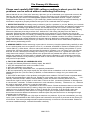
ANTENNA EXPERIMENTING
Since one wavelength (λ) at AM broadcast frequencies is over 950 feet, and
the distance of only ten feet is allowed between the transmitter and antenna,
including the antenna, you may want to experiment with a “loaded”
antenna for better performance.
An easy way to describe what happens when you “load” the antenna is that
we electrically increase the “length” of the antenna without increasing the
mechanical “length” of the antenna. Our goal is to approximate a functional
portion of the full wavelength (i.e. λ/4 or λ/8)
Using an 8 foot whip antenna, a series inductance of about 350 µH is
required to properly load the circuit. Older CB radios and car stereos usually
use a large inductor in series with the power lead, typically 100 to 150 µH.
Two or three of these coils placed in series and connected to a whip can do
the job.
As long as you’re at it , you can try to “roll your own” loading coil using a
common paper tube from your paper towel dispenser.
Start by shellacking or otherwise clear coating a cardboard tube to “stiffen”
the cardboard. Then, using wire from an old transformer or other type of
“magnet” wire (available at a local electronics supply shop or Radio Shack)
AM1 • 17
8 ' WHIP
Paper
TubeTU
PAPER
To Transmitter
TO TRANSMIT
wind consecutive “loops” around the
tube.
For a frequency of 1000 KHz (or 1
MHz) you’ll need to wind 190 turns of
wire around the tube for the proper
inductance!
Connect an 8 foot whip antenna to one
end of the coil and the other end to the
center pin of the antenna output jack.
Experiment with different designs to
determine which antenna type works
best for you.
CONCLUSION
We sincerely hope that you have enjoyed the construction and use of this
Ramsey Kit. As always, we have tried to compose our manual in the easiest,
most “user friendly” format that is possible. As our customers, we value your
opinions, comments, and additions that you would like to see in future
publications. Please submit comments or ideas to:
Ramsey Electronics Inc.
Attn. Hobby Kit Department
590 Fishers Station Drive
Victor, NY 14564
And once again, thanks from the folks at Ramsey!
AM1 • 18
The Ramsey Kit Warranty
Please read carefully BEFORE calling or writing in about your kit. Most
problems can be solved without contacting the factory.
Notice that this is not a "fine print" warranty. We want you to understand your rights and ours too! All
Ramsey kits will work if assembled properly. The very fact that your kit includes this new manual is
your assurance that a team of knowledgeable people have field-tested several "copies" of this kit
straight from the Ramsey Inventory. If you need help, please read through your manual carefully, all
information required to properly build and test your kit is contained within the pages!
1. DEFECTIVE PARTS: It's always easy to blame a part for a problem in your kit, Before you conclude
that a part may be bad, thoroughly check your work. Today's semiconductors and passive components
have reached incredibly high reliability levels, and its sad to say that our human construction skills
have not! But on rare occasion a sour component can slip through. All our kit parts carry the Ramsey
Electronics Warranty that they are free from defects for a full ninety (90) days from the date of
purchase. Defective parts will be replaced promptly at our expense. If you suspect any part to be
defective, please mail it to our factory for testing and replacement. Please send only the defective part
(s), not the entire kit. The part(s) MUST be returned to us in suitable condition for testing. Please be
aware that testing can usually determine if the part was truly defective or damaged by assembly or
usage. Don't be afraid of telling us that you 'blew-it', we're all human and in most cases, replacement
parts are very reasonably priced.
2. MISSING PARTS: Before assuming a part value is incorrect, check the parts listing carefully to see
if it is a critical value such as a specific coil or IC, or whether a RANGE of values is suitable (such as
"100 to 500 uF"). Often times, common sense will solve a mysterious missing part problem. If you're
missing five 10K ohm resistors and received five extra 1K resistors, you can pretty much be assured
that the '1K ohm' resistors are actually the 'missing' 10 K parts ("Hum-m-m, I guess the 'red' band
really does look orange!") Ramsey Electronics project kits are packed with pride in the USA. If you
believe we packed an incorrect part or omitted a part clearly indicated in your assembly manual as
supplied with the basic kit by Ramsey, please write or call us with information on the part you need
and proof of kit purchase.
3. FACTORY REPAIR OF ASSEMBLED KITS:
To qualify for Ramsey Electronics factory repair, kits MUST:
1. NOT be assembled with acid core solder or flux.
2. NOT be modified in any manner.
3. BE returned in fully-assembled form, not partially assembled.
4. BE accompanied by the proper repair fee. No repair will be undertaken until we have received the
MINIMUM repair fee (1/2 hour labor) of $25.00, or authorization to charge it to your credit card
account.
5. INCLUDE a description of the problem and legible return address. DO NOT send a separate letter;
include all correspondence with the unit. Please do not include your own hardware such as
nonRamsey cabinets, knobs, cables, external battery packs and the like. Ramsey Electronics, Inc.,
reserves the right to refuse repair on ANY item in which we find excessive problems or damage due
to construction methods. To assist customers in such situations, Ramsey Electronics, Inc., reserves
the right to solve their needs on a case-by-case basis.
The repair is $50.00 per hour, regardless of the cost of the kit. Please understand that our technicians
are not volunteers and that set-up, testing, diagnosis, repair and repacking and paperwork can take
nearly an hour of paid employee time on even a simple kit. Of course, if we find that a part was
defective in manufacture, there will be no charge to repair your kit (But please realize that our
technicians know the difference between a defective part and parts burned out or damaged through
improper use or assembly).
4. REFUNDS: You are given ten (10) days to examine our products. If you are not satisfied, you may
return your unassembled kit with all the parts and instructions and proof of purchase to the factory for
a full refund. The return package should be packed securely. Insurance is recommended. Please do
not cause needless delays, read all information carefully.
AM1 • 19
AM1 AM BROADCAST TRANSMITTER
Quick Reference Page Guide
AM1 Circuit Description ................. 4
Schematic Diagram ....................... 6
Parts Layout Diagram .................... 7
Parts List .........................................8
Assembly Instructions .................... 9
Antenna Considerations ...............13
Alignment Procedures ..................14
Experimental Broadcasting ...........14
FCC Information ...........................16
Antenna Experimenting ................18
Ramsey Kit Warranty ....................19
REQUIRED TOOLS
• Soldering Iron (WLC100)
• Thin Rosin Core Solder (RTS12)
• Needle Nose Pliers (MPP4 or RTS05)
• Small Diagonal Cutters (RTS04)
ADDITIONAL SUGGESTED ITEMS
•
•
•
Helping Hands Holder for PC Board/Parts
(HH3)
Technician’s Tool Kit (TK405)
Desoldering Braid (RTS08)
Manual Price Only: $5.00
Ramsey Publication No. MAM1
Assembly and Instruction manual for:
RAMSEY MODEL NO. AM1 BROADCAST AM
TRANSMITTER KIT
RAMSEY ELECTRONICS, INC.
590 Fishers Station Drive
Victor, New York 14564
Phone
(585) 924-4560
AM1 • 20
Fax
(585) 924-4555
www.ramseyelectronics.com
TOTAL SOLDER POINTS
99
ESTIMATED ASSEMBLY
TIME
Beginner .............. 3 hrs
Intermediate......... 1.5 hrs
Advanced ............. 1 hr