1
Installation
Epicure ® Cooktop
Models:
Part No. 65162
Rev. K
ESG366,
ESG486
Instructions
Important Safety Instructions ..........................................
Important Information About Safety Instructions ..............
General Safety Precautions .............................................
Installation Requirements ................................................
Electrical Requirements ...................................................
Gas Supply Requirements ...............................................
Product Dimensions .........................................................
Cabinet and Countertop Layout .......................................
Cabinet/Cutout Dimensions .............................................
1
1
2
3
3
3
3
4
5
Installation Instructions ....................................................
8
Unpack the Cooktop ........................................................
8
Cooktop Installation..........................................................
8
Gas Line Connection .......................................................
9
Burner Component Installation ........................................ 9
Verifying Proper Operation .............................................
10
Installation Checklist .......................................................
11
Wiring Diagram ................................................................
12
Important:
•
Installer: In the interest of safety and to minimize problems, read these installation instructions completely and carefully before you begin the installation process. Leave these installation instructions with the customer.
•
Customer: Keep these installation instructions for future reference and the local building inspector's use.
If You Need Help...
Product Data Label
If you have questions or problems with installation, contact
your Dacor ®dealer or the Dacor Customer Service Team.
For repairs to Dacor appliances under warranty call the
Dacor Distinctive Service line. Whenever you call, have the
model and serial number of the appliance ready. The model
and serial number are printed on the appliance data plate.
•
The product data label contains the model and serial
number information and the electrical and gas supply
requirements.
It is attached to the bottom of the chassis.
Model Identification
ESG366SCH/LP/H
Dacor Customer Service
Phone:
(800) 793-0093 (U.S.A. and Canada)
Monday -- Friday 6:00 A.M.to 5:00 P.M.Pacific Time
SIZE (in inches)
Web site:
GAS TYPE
www.Dacor.com
Dacor Distinctive Service (repairs under warranty only)
Phone:
(877) 337-3226 (U.S.A. and Canada)
Monday -- Friday 6:00 A.M.to 4:00 P.M.Pacific Time
T1
No character = Natural Gas
LP = Liquid Petroleum (Propane)
ALTITUDE
H = High Altitude Model, 4000 ft.(1219 m) and up
No character = Equipped for low altitude operation
All specifications
are subject to change without notice. Dacor assumes no liability for changes to specifications.
© 2007 Dacor, all rights reserved.
Important Information About
Safety Instructions
The Important Safety Instructions and warnings in
this manual are not meant to cover all possible problems and conditions that can occur. Use common
sense and caution when installing, maintaining or operating this or any other appliance.
•
Always contact the Dacor Customer Service Team
about problems and conditions that you don't understand. See Customer Service Information.
_] DANGER
Do n0t t0uch any electrical switch 0ruse
any electrical
devices, including the telephone, in your building.
From a neighbors'- phone, immediately call the gas
supplier. Follow the gas supplier's instructions,
you Cannot c0ntact the gas supplier, call the fire
department:
[_ DANGER
Safety Symbols and Labels
IMPORTANT: Do not st0re 0r use combustiblel flammable
Immediate hazards that WILL
[_ DANGER
or death.
I injury
WARNING
Hazards or Unsafe practices that COULD result in severe
personal injury or death.
CAUTION
or explosive Vapors and liquids (such as gasoline)on or
in the vicinity of this or any other appliance. A!so keep
items that could explode, such as aerosol cans, away
from the cooktop. Do not store flammable o[ exp!osiv e
materia!s in adjacent cabinets or areas (including above
and below the cooktop):
WARNING
WARNING 'NEVER
Hazards or unsafe practices that COULD result in minor
personal injury or property damage: ..................................................................
WARNING
TO REDUCE THE RISK OF INJURY TO PERSONS IN
a. SMOTHER
FLAMES with a close-fitting lid; cookie
sheet or metal tray, then turn off the burner, BE
CAREFUL
TO PREVENT BURNS: If the flames do
C DONOT
USE WATER inCUding Wet dish cl0ths 0r
towels- a vi01ent steam explosion may resulti
d
use a fire extinguisher ONLYif:
0 You have a Class ABC extinguisher, and you
already know how t0 operate iL
use this appliance as a space
heater to heat or Warm the rooml Doing so may result
in carbon monoxide poisoning and overheating of the
appliance.
WARNING
WARNING - NEVER cover any slots, holes or passages
on the cooktop and cooktop chassis. Doing so blocks
air flow through the cooktop and may cause carbon
monoxide poisoning. Aluminum foil linings may also trap
heat, causing a fire hazard. Keep all slots, holes and
passages clear of grease and grime.
CALIFORNIA
PROPOSITION
65 WARNING
The burning of gas cooking fuel generates some
by-products that are on the list of substances which
are known by the State of California to cause cancer or
reproductive harm. California law requires businesses
to warn customers of potential exposure to such
substances. To minimize exposure to these substances
always operate this unit according to the use and care
manual, ensuring you provide good ventilation when
cooking with gas.
0 The fire is small and contained in the area where
it started
The fire department is being called:
You can fight the fire with your back t0an exit,
READ AND SAVE THESE INSTRUCTIONS
_mCD_
1
General Safety Precautions
To reduce the risk of fire, electric shock, serious injury or death when using your appliance, follow basic safety precautions, including the following:
WARNING
WARNING
, Read the accompanying use and care manual comp!etely before opera{ing this appliance_
'
Keep packaging materials away from children:Plastic
• If
yo u receive a damaged producti immediately contact y0ur dealer 0r builder, Do not install or use a
damaqed appliance
• This cooktop must be properly installed and grounded
bya
qualified installer according to these instal!ati0n
instructions prior to use. The nstaller should show the
customer the location of the gas shut off Va ve and
the power cord so that they know where and how to
turn offthe gas supply and disconnect power to the
cooktop: Proper installation is the responsib litY of the
i
Customer.
Installati0ns with less than 2112 (64 mm)from
Do not climb on any part of the appliance.
•
To avoid a fire hazard, do not hang flammable or heat
sensitive objects over the cooktop.
•
Do not leave children alone or unattended in the area
around the cooktop. Do not allow children to play
with the controls or touch other parts of the cooktop.
Do not store items of interest to children on top of
or above the cooktop. Children could be burned or
injured while climbing on the appliance.
•
Clean the cooktop thoroughly before operating it for
the first time. Make sure that all the cooktop parts are
dry before lighting a burner.
Keep flammable items, such as paper, cardboard,
plastic and cloth away from the burners and other hot
surfaces. Do not place such items on the cooktop.
Do not allow pot holders to touch hot surfaces or gas
burners.
the
rear of the co0kt0p toa combustible material must
use Dacor backg uard model AE B3609, AE B3612,
(for
model ESG366) AEB4809, AEB4812(for model ....
ESG486) or a non-combustible material. See the lat/estversionofANSI
Z223.1:
•
Do not wear loose or hanging apparel while using the
cooktop. Do not allow clothing to come into contact
with the cooktop and surrounding areas during and
immediately after use. Do not use towels or bulky
cloth as pot holders.
face (countertop)ventilation
systeml Dacor strongly :
recommends the installation of a range hood or raised
vent in conjunction With this appliance:
•
If the cooktop is near a window, do not use long curtains as window treatment. The curtains could blow
• Doric t install, repair or replace any part of the
cookt0p
unless specifically recommended in the !iterature accompa hying it. A qua!ified servic e technician
should perform al other serv ce. Do not tamper with
the controls Do not operate the cooktop without the
•
'
•
,
'
DOnot use this appliance in Combination With a sur _
knobs and tdm rings in Place
Before semicing or instal!ing this cooktopl make sure
that the gas supply is turned off at the gas supply
Valve and that the power plug is disconnected from
the electrical outlet!
DO not €onnect th S cooktoP to the gas supply Without
the supplied gas pressure regulator installed;
Disconnect the power plug from the e!ectrical outlet
before
•
cleaning. Clean this appliance only in the man-
ne[ sPecified in the use and care manual:
Only use the cooktop for cooking tasks expected of a
hom e appliance as outlined in the literature accompa-
COOKTOP OR THE SURROUNDING AREAS
DURING OR IMMEDIATELY AFTER USE.
2
•
_mC_
over the cooktop and create a fire hazard.
Non-stick coatings, when heated, can be harmful to
birds. Remove birds to a separate, well-ventilated
room when operating the cooktop.
IMPORTANT - This appliance is equipped with a
three prong grounding plug for your protection against
possible electric shock hazards.
Plug it only into a dedicated,
grounded three prong electrical
outlet. It is the responsibility
of the customer to make sure
the proper type of outlet is
installed. Do not under any
circumstances:
•
Cut or remove the third (ground) prong from the
power cord.
•
Use an adapter plug.
•
Use an extension cord.
•
Use a power cord that is frayed or damaged.
•
Connect to an electrical outlet with a ground fault
interrupter (GFI).
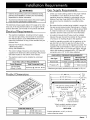
Gas Supply Requirements
WARNING
'
Observe all governing c0des and ordinances during
planning and installation. Contact your local building
!
department for furtherinformationl
prevent an electric shock hazardl the Power sUpplY
must meet the specifications stated below.
The electrical and gas supply data on this page is for reference only. If the requirements below do not agree with the
product data label, use the data on the product data label.
Electrical Requirements
The electrical installation, including minimum supply
wire size and grounding, must be done in accordance
with National Electric Code ANSI/NFPA 70 and local
codes and ordinances. A copy of this standard may be
obtained from:
National Fire Protection Association
1 Batterymarch Park
Quincy, MA 02269-9101
The correct voltage, frequency and amperage must be
supplied to the electrical outlet according to the product
data label located on the bottom of the chassis.
•
The electrical outlet must be installed by a licensed
electrician.
ELECTRIC CIRCUIT REQUIREMENTS
Circuit Required
120 Vac 60Hz,
15 Amp. (3 wire)
'
Total Connected
Load
0.25 Amp @ 120 Vac, 60 Hz
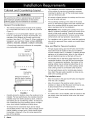
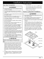
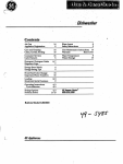
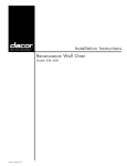
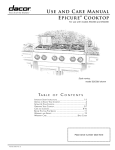
Product Dimensions
Check your local building codes for the proper method
of installation. In the absence of local codes, this
appliance should be installed in accordance with the
National Fuel Gas Code ANSI Z223.1/NFPA 54. The
gas service must be installed by a qualified professional
Be certain that the cooktop being installed is correct for
the gas service being provided (natural gas or LP gas).
Also, if operating the cooktop at an altitude above 5000
ft. (1524 m) make sure it is equipped for high altitude
operation. See the inside cover for more information.
An external manual shut-off valve must be installed
between the gas inlet and the cooktop for the purpose
of turning on or shutting off gas to the appliance.
Install the regulator provided with the appliance in the
gas line that runs from the gas shut off valve to the
cooktop gas inlet. Use only the regulator provided. The
regulator inlet accommodates a 3/4" supply line and is
also compatible with a 1/2" house gas supply. The gas
inlet to the cooktop is equipped with a 1/2" male NPT
connection and a 1/2" to 3/4" elbow attached.
GAS SUPPLY PRESSURE REQUIREMENTS*
Manifold"
Pressure
Minimum Gas
sUpply Pressure
Natural Gas
4" Water Column
5" Water Column
Propane (LP)
10" Water
Column
11" Water Column
_as
_
lype
Maximum gas supply pressure for all models is 1/2 p.s.i.
q
27" (686 mm)
q
p
Trim:
3/8"
"1 (10 mm)
26 1/2" (673 mm)
I
25 1/2" (648 mm)
_
?
l'
,,
countertop
'_
'
3 1/2" (/9 mm)
thick
I
7 3/4
_f
1 1/8 (29 mm) cooking surface
-height (grate level) above ,_d
l-, 1
"/
_i_]_
_
_
_..\'_..D)
Gas inlet*
1/2" male
_v
connection
3/4" female
Power cord,
36" long
"-t-"
!
t
,,
I, (19_mm)
I
_,
,,
L1(271/16mm)
connection, elbow
may be removed
*Attach supplied regulator and gas
line from bottom or rear of unit
COOKTOP WIDTH (A)
ESG366
35 7/8" (911 mm)
ESG486
47 7/8" (1216 mm)
SIDE VIEW
Product tolerances: +1/16" (+1.6 mm)
unless otherwise noted.
I_mCD_
3
The installation must allow access to the underside
of the cooktop for service and inspection purposes,
including the ability to turn off the cooktop gas supply
valve and electrical outlet.
Cabinet and Countertop Layout
WARNING
To av0id the risk Of fire or pers0nal njurY, al!
and maximum specified c earances on this and the
fol ow ng pages must be maintained or exceeded
General
I
•
The countertop overhang on the sides of the cutout
shown on the following pages covers the recessed portions of the cooktop behind the control panel and creates a seamless look for the installation.
Considerations
The minimum distance from the back of the cooktop
to a combustible rear wall is 2 1/2" (64 mm) minimum
(Figure 1).
Installation of a non-combustible material* (up to the
hood) or a backsplash is always recommended, and
mandatory if the distance to the back wall from the
cooktop is less than 2 1/2" (Figure 2). When installing a
backguard, use only Dacor model numbers AEB3609,
AEB3612 (ESG366), AEB4809 or AEB4812 (ESG486).
* Consult local codes and ordinances for acceptable
non-combustible materials.
Combustible
rear wall _
2 1/2" (64 ram) Min. to
combustible rear walt
,
N
\
\
\
N
\
X
\
\
\
\
\
FIGURE 1
IMPORTANT: When installing the cooktop into a laminated or synthetic countertop, radius the corners of the
cutout to help avoid cracking. Consult the countertop
manufacturer's instructions for minimum corner radius,
reinforcement and heat protection requirements.
•
than 2 1/2"
\
•
The gas supply piping, gas shut-off valve and the electrical outlet must be located so they do not interfere
with the cooktop when it is installed. If installing another
appliance in the cabinet below, allow for the routing of
gas and electrical service out the back of the unit.
•
The shaded area on the facing page shows the recommended location of the gas inlet and the electrical
outlet. For replacement purposes, the location of the
existing utilities may be utilized provided they do not
interfere with the sides or rear of the cooktop. Check
local building codes for permissible utility locations.
•
For best performance and to minimize gas pressure
loss, attach the gas supply regulator as close as possible to the cooktop gas inlet.
The installation
\
\
Allow for access to the electrical outlet, when the
cooktop is in place so that the power cord may be easily disconnected if the unit needs service.
\
\
\
\
Allow for the (36") power cord reaching the electrical
outlet.
\
Carefully check the location where the cooktop is to be
installed. For best performance, the cooktop should be
installed away from drafts caused by doors, windows
and heating and air conditioning outlets. To reduce the
risk of personal injury from reaching over a hot appliance, avoid cabinet installations directly above.
To reduce the risk of personal injury and to reduce
accumulated smoke in the room, Dacor strongly recommends installing a range hood. A hood should project
horizontally a minimum of five (5)inches beyond the
face of the cabinets.
4
_mC_
must:
Allow for access to the gas shut-off valve and regulator
when the unit is installed.
\
\
\
FIGURE 2
For installations with a raised vent, install this appliance
only with the approved Dacor raised vent models listed
on page 6.
Gas and Electric Service Location
Combustible
rear wall _
Backguard mandatory if
gap from back of cooktop
to combustible wall is less
All contact surfaces between the cooktop and the counter must be solid and level.
•
If a raised vent is to be installed, allow for access to the
gas supply valve and electrical outlet when the raised
vent is in place.
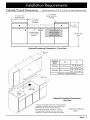
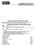
Cabinet/Cutout
Dimensions
Cabinet tolerances +1/16"-0
(+1.6 mm, O) unless otherwise noted.
1 1/2" (38 mm)
typical countertop
thickness
10" (254 mm) to
combustible side
_- wall Min. both sides --_
_
\
1/2"
(13 mm)
overhang,
both sides
J
!
•
Cooktop platform
1" (25 mm) Min.
thickness
36" (914 mm)
typical
Cabinet/Countertop
Dimensions
- Front View
13" (330 mm)
max. 3
ESG366
36" (914 mm)
36" (914mm)*
42" (1067 mm)**
ESG486
48" (1219 mm)
48" (1219 mm)*
54" (1372 mm)**
Hood
* Minimum ** Recommended
See note 2
18" (457 mm)"
Min.1, 3
30" (762 mm)
Min. 1
Cutout for
utility access
Top of
finished
counter
Cabinet/Countertop
Dimensions
ISO View
-
1 Vertical to combustible surface from cooktop grate level;
if installing an overhead vent hood, also check the hood
specifications for minimum required clearances.
2 See Cabinet/Countertop
Dimensions
- Top View
3 Not applicable for cabinets more than a horizontal
distance of 10" (254mm) from the edge of the cooktop.
Continued on following
pages...
_mCD_
5
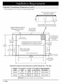
Cabinet/Countertop
Dimensions (cont.)
Cutout tolerances +1/16" -0 (+1.6 ram, O) unless otherwise noted.
Gas and electrical
connections
on
right side of of chassis
Gas connection and power cord may be
routed through bottom or back of chassis
Increase countertop and overhang
additional 2 1/2" (64 mm) Min. for
combustible rear wall above
countertop
/
Non-combustible
rear walt, rear of
mounting platform
/
I
,L
I
3/8" (13 mm)
countertop overhang
countertop
Gas/electrical utility cut-out in right rear corner of
mounting platform 8" W X 6" D (203 mm X 152 mm),
if gas and electrical are routed through bottom
overhang
24 5/8"
(625 mm)
''1
!
1/2" (13 mm)---_l
(_
10" (254 mm) min.
to combustible wall
above countertop,
both sides
Ii
1/2" (13 mm)
_- countertop
overhang
I
I
7
Hole 1/2" dia. (13 mm),
2 places, through platform
for hold down bolts
O
11 7/16"
(291 mm)
c
I
(1)
I o_
0
o
1" thick mounting platform Min.
1-,
ollo
_h
\
D
_-
Cabinet face
below countertop
overhang
D
B
Cabinet/Countertop
Cutout
Dimensions
without
Raised Vent - Top View
Cooktop
Model
B' Cutout
Width
ESG366
36"
(914 mm)
16 5/8"
(422 mm)
33 1/2"
(851 mm)
ERV36, PRV36
ESG486
48"
(1219 mm)
20 13/16"
(529 mm)
43 1/2"
(1105 mm)
ERV48, PRV48
Vent Cutout
Approved Raised
Vent
Models
IMPORTANT: Use only the raised vent models specified.
6
_mC_
_
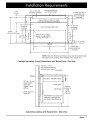
2" (51 mm)
1" (25 mm)
Non combustible rear
wall recommended
3/8" (10 mm) Min.
countertop overhang
2 5/8"
(67 mm)
!
_d
10" (254 mm) Min. to
combustible wall
/
t
I'
LI
'1
I,
E
Open to below to allow for raised
both sides ,
_ above
I
vent, gas and electrical connections
countertop,
1
I
1_--1/2" (13 mm)
countertop
I
overhang
1/2"
(13 mm)--_l
24 5/8"
15"
(625mm)(381mm)
--f-
I
I
|
/
11 7/16" .._
_ I
_¢
(291 mm)
1" thick mounting platform
Min.
I
countertop
overhang
c)
O
Hole 1/2" dia. (13 mm),
2 places, through platform
for hold down bolts
t-
8-
>
O
__
:_ "-- 2" (51 mm)
"_
1" (25 mm)
I.
D
l_iI,e'
D
Cabinet face
below countertop
overhang
B
Ii
NOTE: Gas and electrical connections may only be routed through
the bottom of the cooktop when installed with a raised vent.
Cabinet/Countertop
Cutout
Dimensions
with Raised Vent - Top View
3/8" Min. (10 mm)
flat countertop overhang
required behind cutout
Countertop
/
A
*-.......
Stiffener.
........
t]-1
ESG366 or ESG486 cooktop
ILLJ
3/8" Min. (10 mm)-.
space behind
raised vent
chassis to clear
stiffener
/
Control panel
Minimum
countertop
height:
30 1/4"
(768 mm)
Cabinet face_l
Dacor approved
raised vent
]
-.
IMPORTANT: See raised vent
installation instructions for
duct system layout/planning
m
=
....
/.
.1. T -.J
i I
i I
i I
I i
Cabinet/Countertop
with Raised Vent - Side View
_mCD_
7
Unpack the Cooktop
Cooktop Installation
WARNING
If th e gas and electric service provided does not
meet the PrOduCt specifications, do not proceed with
the installationl Call the dealer, the gas supplier ora
WARNING
install it only after the cooktop is mounted in its permanent
positionl
DO not over-tighten the h01d down bolts, Ove r tighten,
ing the hold down bolts may result in improper operation of the dual gas burners.
licensed electricianl
The cooktop is heavy, A minimum of two people are
required to safely install it.
Unpack the parts box and verify that all required components have been provided. If any item is missing or damaged, please contact your dealer immediately. Do not install
a damaged or incomplete appliance. The customer must
report cosmetic issues within 30 days of installation.
•
Grates (3) *
•
Burner caps (6)
•
Burner rings (6)
•
Hold down bolts/washers (2 sets)
•
Regulator
•
Dacor Stainless Steel Cleaner
•
Igniter cleaning brush
•
Literature kit
•
WOK ring
•
Griddle
•
Simmer plate
•
Spatula
• Model ESG486 comes with (3) 14 inch grates. Model
ESG366 comes with (2) 10-inch grates and (1) 14-inch
grate.
8
_mC_
IMPORTANT
DO not us e a hardening compound or caulk to
Permanently sea! the cooktop into p!ace. The cooktop
must be readily removable if service is requiredl Removal
of sealant to service the unit will be performed at the
customer!s expense.
Lower the cooktop into the cutout while feeding the
electrical cord into the utility cutout. Center the cooktop
in the cutout.
2.
Secure the cooktop to the countertop using the two (2)
provided hold-down bolts and washers provided. Do
not overtighten the bolts.
Gas Line Connection
3.
WARNING
•
Verify that the gas supply meets specifications
connection. See page 3.
•
The maximum gas supply pressure to the regulator
must never exceed ½ pounds per square inch (psi) or
3.5 kPa.
•
Do not install or use the cooktop without the included
gas regulator installed.
•
Ensure that the arrow on the regulator points in the
direction of the gas flow, towards the cooktop.
•
Do not apply excessive pressure when tightening gas
connections and fittings.
•
Do not use Teflon tape or plumber's putty on flexible
gas line connections.
•
Test the gas lines for leaks as instructed before use.
Do not use a flame to check for leaks.
•
The cooktop and shut-off valve must be disconnected
fromthe gas supply piping system during any pressure testing exceeding ½ psi (3.5 kPa).
•
The cooktop must be isolated from the gas supply piping system by closing the shut-off valve to the cooktop
during any gas supply piping system pressure testing
equal to or less than ½ psi (3.5 kPa).
¢
Turn on the gas supply valve and check all lines
and connections for leaks using a soap and water
solution or a gas leak detector.
¢
Turn the gas supply valve off.
WARNING
'
Never attempt t0 operatethe
burner parts removedl
cooktopwith
anY of the
, DO not attempt to adjust the burner air mixture setngsl All adjustments are preset at the factoryl
.....
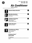
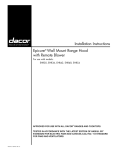
Remove the burner parts and grates from their shipping
packages.
•
Install the burners as shown. When installing the burner rings, insert the five (5) tabs on the bottom of each
ring into the tabs on the top of each burner base. Twist
each piece back and forth slightly until it drops completely into place. The burners will not operate properly
unless all of the burner pieces are properly seated.
•
Gently set the grates on top of the spill trays. Make
sure that the rubber feet are positioned in the dimples.
On model ESG366, the center grate is larger than the
other two.
Grate
/
For LP gas installations, the LP gas tank must have
its own high-pressure regulator in addition to the pressure regulator supplied with the cooktop.
Within the C0mmonwealth Of Massach Usetts th!s
appliance mus t be installed by a licensed plumber 0rgas
fitter. .......................
.
Turn all cooktop control valves to the OFF position.
Burner Component Installation
IMPORTANT
1,
¢
before
• The gas supply pressure for testing the regulator setting shall be at least 1 inch water column (249Pa)
above the specified manifold pressure. See page 3.
•
Check for gas leaks:
Attach the gas pressure regulator (included with the
cooktop) to the gas inlet on the cooktop, The inlet is
located on the bottom, at the right rear portion of the
chassis, For tight installations, the regulator may be
installed upstream from the pipe nipple, anywhere
between the shut-off valve and the cooktop, For best
performance, minimize gas pressure loss by attaching
the regulator as close as possible to the cooktop gas
inlet,
I
Burner cap
I
Burner ring
I
I
Top frame
Burner base
(fixed)
Complete connection of the gas supply to the cooktop
by installing a minimum ½" flexible gas line (not included) between the pressure regulator and the shut-off
valve.
_mCD_
9
Verifying Proper Operation
WARNING
Make sure that power t0 the electrical outlet is turned
off at the circuit breaker or fuse box and that the gas is
turned off at the gas supply valve before proceeding.
,
use
1.
Make sure all the cooktop burner controls are in the
OFF position.
2.
Connect the power cord to the electrical outlet.
3.
Turn on power to the electrical outlet at the circuit
breaker or fuse box.
,
6.
Dacor is not responsible for the cost of correcting problems
caused by a faulty installation.
The cooktop must be properly grounded at all times
when electrical power is applied: ...............
Prior to operating the cooktop, read the accompanying
and care manual carefully.
,
If the appliance still does not work, contact Dacor
Distinctive Service at (877) 337-3226. Do not attempt to
repair the appliance yourself. Be sure to have the model
and serial numbers available when you call. See the inside
cover for location.
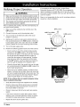
OFF position
/
LIGHT
and HIGH
t
position
o
LOW position
Gently push in and turn one burner control knob at a
time counterclockwise to the HIGH position. Verify that
burner igniters spark, then return the knob to the OFF
position. Repeat for all of the remaining control knobs.
Turn on the gas supply valve.
Perform the following ignition test for all of the burners:
• Push in and turn one of the control knobs counterclockwise to the HIGH position. The igniters for all
the burners will spark. It may take up to four seconds
for the gas from the selected burner to ignite, at
which time the igniters will stop sparking. If ignition
does not occur within four seconds, turn the knob
to the OFF position, wait for at least five minutes to
allow any gas to dissipate, then repeat the test.
Burner Control
Knob
Burner indicator
• Once the burner lights, the control knob can be rotated counterclockwise from HIGH to LOW to adjust the
flame height progressively.
When the unit is installed properly, the flame will be
steady. It will also have a sharp, blue inner cone that
will vary in length proportional to the burner size. The
flame will be reduced by the Smart Flame TM feature
under the grate fingers to increase grate life.
NOTE: If the cooktop does not operate properly, follow
these troubleshooting steps:
•
Verify that power and gas are supplied to the cooktop.
•
Check to make sure that the power plug is connected
to the electrical outlet and that power is turned on at
the circuit breaker or fuse box.
•
Check to make sure that all burner parts are properly
seated.
•
If the burner continues to spark after ignition without
stopping, have a licensed electrician check the electrical outlet for proper grounding or reversed polarity.
•
Repeat the above burner ignition test.
10 c_acar
Normal Flame
Appearance
light
Installation Checklist
WARNING
-
To ensure a safe and proper installation, the following checklist should be completed by the installer to
ensure that no part of the installation has been overlooked.
°
Proper installation is the responsibility of the homeowner. The importance of proper installation of your
Dacor cooktop cannot be overemphasized.
[]
Is the electrical outlet for the cooktop grounded and
located according to these instructions and in accordance with all applicable electrical codes? See pages 3
and 4.
[]
Is the gas service for the cooktop located and installed
according to these instructions and in accordance with
all applicable codes? See pages 3 and 4.
[]
Has the gas supply inlet pressure been measured to
ensure that it does not exceed the maximums stated in
these instructions? See page 3.
[]
Is the cooktop secured using the provided hold-down
bolts and washers? See page 8.
[]
Is the cooktop connected to the gas supply according
to these instructions and in accordance with all applicable codes? Did the installer check the gas supply for
leaks? See page 9.
[]
Are all burner parts and grates properly installed
according to these instructions? See page 9.
[]
Has proper operation been verified?
[]
Has the warranty been activated on-line or the warranty
card filled out completely and mailed?
ctacor
11
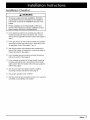
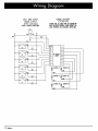
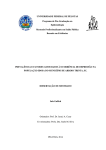
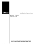
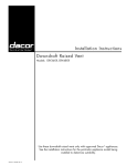
WIRINGDIAGRAM
ESG3GG/48G
120V,60Hz0,025A
POWER SUPPLY
AFTER SERVICING
VERIFYPROPERBPERATIBN
L
WHT
CAUTmN,
LABEL
ALLVIRESPRIOR
TODISCONNECTION
VHENSERVICING
CONTROLS,
VIRINGERRORSCAN
CAUSEIMPROPER
AND DANGEROUS
OPERATION,
N
!
BLK
GRN
BLK =
GN])
N
$6
A
I
i
5
$5
RE-IGNITOR
-6 PgINT $4
4
S3
6
3
$2
2
Sl --
I
"_'_S3
°
BLi
(_
IGNITER
MR
HT
IGNITER
LF
HT
_
IGNITER
RF
VHT
_
IGNITER
RR
VHT
IGNITER
LR
HT
0
BLK
IGNITER
MF
HT
12 _acar
®
The Life of the Kitchen?
Dacor
• Phone: (800)793-0093
• FAX: (626)403-3130
• www.Dacor.com