1
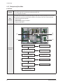
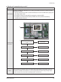
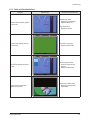
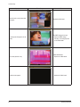
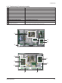
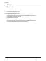
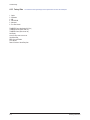
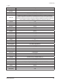
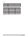
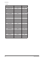
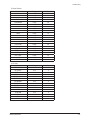
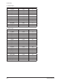
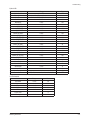
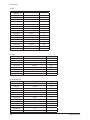
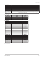
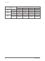
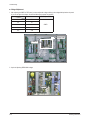
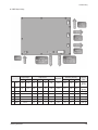
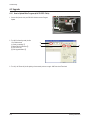
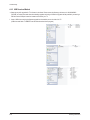
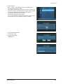
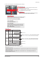
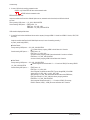
Troubleshooting
4. Troubleshooting
4-1 Troubleshooting
4-1-1 First Checklist for Troubleshooting
1. Check the various cable connections first.
- Check to see if there is a burnt or damaged cable.
- Check to see if there is a disconnected or loose cable connection.
- Check to see if the cables are connected according to the connection diagram.
2. Check the power input to the Main Board.
3. Check the voltage in and out between the SMPS ↔ Main Board, between the SMPS ↔ X, Y Main Board, and between the
Logic Boards.
Samsung Electronics
4-1
Troubleshooting
4-1-2 Checkpoints by Error Mode
■ No Power
Symptom
- The LEDs on the front panel do not work when connecting the power cord.
- The SMPS relay does not work when connecting the power cord.
- The unit appears to be dead.
Major
Checklist
The SMPS relay or the LEDs on the front panel does not work when connecting the power cord if the cables
are improperly connected or the Main Board or SMPS is not functioning. In this case, check the following:
- Check the internal cable connection.
- Check the fuses.
- Check the output voltages of the SMPS.
- Replace the Main Board.
3
4
2
5
1
1
Check that the AC power cord is connected
No
Connect the AC power cord
Yes
Troubleshooting
Procedures
If LED is set up as being ON when
POWER-ON, check the ligt-on in LED
No
Replace Fuse (FE801)
Yes
2
Is the AC Inlet socket connected?
No
Connect AC Inlet socket
Yes
3
Check the connection between Fuse FE801 No
for checking SMPS’s Fuse
Replace Fuse
Yes
4
Check the No. 4 STAND-BY power of
CN801
No
Replace the SMPS
Yes
5
4-2
Replace the Main Board
Samsung Electronics
Troubleshooting
■ When the unit is repeatedly turning on and off
Symptom
Major Checklist
- The SMPS relay is repeatedly turning on and off.
In general, the SMPS relay repeatedly turns on and off by the protection function due to a defect on a board
connected to the SMPS.
- Disconnect all cables from the SMPS, operate the SMPS alone and check if the SMPS works properly and if
each voltage output is correct.
- If the symptom continues even when SMPS is operated alone, replace the SMPS.
- If the symptom is not observed when operating the SMPS alone, find any defective assemblies by
connecting the cables one by one.
1
1
Troubleshooting
Procedures
Check that the Va,Vs voltage of SMPS
match the voltages marked on the module
label
No
Replace the SMPS
Yes
Did problem improve?
No
Replace the Main Board
Yes
Did problem improve?
No
Replace the Y Main Board
Yes
Did problem improve?
No
Replace the X Main Board
Yes
Did problem improve?
No
Replace the Logic Board
Yes
Did problem improve?
Caution
No
Replace the X, Y Buffer Board
When separating and connecting the cables such as CN800, CN802, CN803, CN804 of the Main SMPS, U4004 of the
X Main Board, and CN5005 of the Y Main Board, a spark may be generated by the electric charge of the high capacity
capacitor. Therefore, wait some time after disconnecting the power cord from the unit.
Samsung Electronics
4-3
Troubleshooting
■ No Sound
Symptom
Major Checklist
- Video is normal but there is no sound.
- When the speaker connectors are disconnected or damaged.
- When the sound processing part of the Main Board is not functioning.
- Speaker defect.
2
1
Troubleshooting
Procedures
3
3
1
Is the cable connection between the Main No
Board and the speaker properly connected?
Cable Connection
Yes
2
Check that the voltage of No.7,8 pin of
SMPS CN801 has 18V
No
Replace the SMPS
Yes
Is the speaker output terminal of the Main
Board normal?
No
Replace the Main Board
Yes
3
4-4
Replace the Speaker
Samsung Electronics
Troubleshooting
4-1-3 Faults and Corrective Actions
Symptom
A blank vertical cell (block) appears
on the screen.
Related Image
Causes and Countermeasures
Address buffer defect
- Replace the corresponding
address buffers(E or F)
COF defect (burnt)
- Replace the module
A green screen appears when the
TV is turned on.
The Scale is not reseting
- Replace the Main board
The OSD box appears but there is
no text.
Incorrect program version
- Check the version of each
program
- Replace the Main board
A blank upper (or lower) block
appears on the screen.
Samsung Electronics
Upper/Lower Y Buffer defect
- Replace the corresponding
∙lower buffers
4-5
Troubleshooting
Symptom
Related Image
Causes and Countermeasures
Either the main or sub picture does
not appear.
Replace the Main board
A vertical green line appears on the
screen.
The SMPS voltage is incorrect
- Adjust the SMPS voltage
according to the voltage printed
on the module label
Dim screen (blurred in red)
X-Main board defect
- Replace the X-Main board
A blank screen appears
- Replace the Y-Main board
4-6
Samsung Electronics
Troubleshooting
4-1-4 Troubleshooting Procedures by assembly
No
Assembly
Major Symptoms
1
SMPS-PDP TV
No power, Blank screen, the Relay repeats On and Off
2
ASSY PDP MODULE P-Y MAIN
Blank screen
3
ASSY PDP MODULE P-X MAIN
Blank screen
4
ASSY PDP MODULE P-LOGIC MAIN
Blank screen, Screen noise
5
ASSY PDP MODULE P-Y-MAIN SCAN UPPER
Upper screen is blank
6
ASSY PDP MODULE P-Y MAIN SCAN LOWER
Lower screen is blank
7
ASSY PDP MODULE P-X-MAIN BUFFER BORAD
Corresponding Buffer Board block screen is blank
8
ASSY PDP MODULE P-ADDRESS E BUFFER
Corresponding Buffer Board block screen is blank
9
ASSY PDP MODULE P-ADDRESS F BUFFER
Corresponding Buffer Board block screen is blank
10
ASSY PCB MISC-MAIN
No Power, Abnormal screen for each input source, PIP screen trouble, Sound trouble
ASSY BOARD P-FUNCTION & IR
The side function key does not work properly.
The remote control does not work properly, the LED does not work properly.
11
1
4
0
!
5
3
2
7
6
8
Samsung Electronics
9
4-7
Troubleshooting
4-2 Adjustment
4-2-1 Service Instruction
■ Before Performing After Sales Services
1. Check if the measurement and test equipment is working properly.
2. Secure sufficient work space for disassembling the product.
3. Prepare a soft pad for disassembling the product.
■ Service adjustment item after replacement of Board
<If adjustment equipment is available>
① PDP Option of Factory Mode → set the Factory Data Type item as the suitable value of relevant model.
② Adjust Calibration of Factory Mode for each mode.
③ Adjust White Balance of Factory Mode.
<If adjustment equipment is not available>
① Write down the value of HDMI White Balance of Factory Mode before replacing Board.
② PDP Option of Factory Mode → set the Factory Data Type item as the suitable value of relevant model.
③ Set the value of HDMI White Balance with the value written down before.
4-8
Samsung Electronics
Troubleshooting
4-2-2 How to Access Service Mode
1. General Remote
To Enter: POWER OFF
INFO
MENU
MUTE
POWER ON
(Interval between key strokes: less than 3 sec)
POWER OFF
To Exit:
POWER ON
2. Factory Remote
To Enter: POWER ON
POWER OFF
To Exit:
INFO
Factory Key (Interval between key strokes: less than 3 sec)
POWER ON
Press the Factory key twice with a key stroke interval of more than 1 second (Pressing once enters Aging Mode)
3. Settings when entering Factory mode
- Sharp Screen (Dynamic), Color Tone (Cool1), Factory (Dynamic CE Off)
4. Adjustment Procedures
- Channel ▲▼ Key: Select an item.
- Volume ◀▶ Key: Adjust the value up or down.
- MENU Key : Save the changes to the EEPROM and return to the higher-level mode.
- Using the Numeric (0~9) keys, you can select a channel.
- Using the SOURCE key, you can switch AV modes.
5. Initial SERVICE MODE DISPLAY State
Panel ON Time(Hour)
1. Option Table(Service)
2. WB Adjust
3. Information
CheckSum
T-PRLPEUS-xxxx
T-PRLPEUMD-xxxx
T-PERLDEUC-xxxx
EDID
HDCP
4. Advanced Menu
Month/Day/Year
Hour/Min./Sec.
※The version of the firmware displayed at the bottom of the screen may differ and the firmware is subject to change for the
improvement of product functions.
※If you have adjusted the settings in Service Mode, you have to reset the product.
Samsung Electronics
4-9
Troubleshooting
4-2-3 Factory Data
♦ The underlined are items applied during the service adjustment. None of the others should be adjusted.
1. Option
2. Calibration
3. WB
4. CHECKSUM
5. Advanced
6. Font Data Viewer
T-AMBDFRC-xxxx (Application S/W Ver.)
T-AMBDEUM xxxx (Scaler S/W Ver.)
T-AMBDEUS-xxxx (Sub micom Ver.)
Not Display
xxxx xxxx xxxx xxxx xxxx xxxx xx
Year-Month-Day
EDID : Success/Failure
DTP-LM-xxxx
Date of Purchase : Month/Day/Year
4-10
Samsung Electronics
Troubleshooting
1. Option
Item
Range
Factory Reset
Wb Reset
Panel Inch
37”, 40”
Dimm Type
EXT, INT, INT_NEG, EXT_POS, EXT_NEG
Panel Type
40AMSC100F,46AMSC100F,52AMSC100F,32AMAG50F,32AUAG50F,37AUAG50F,40AMAG50F,
40AUAG50F,40CMAG50F,46AMAG50F,46AUAG50F,46CMAG50F,52AMAG50F,52CMAG50F,26AMAG5
0,26AUAG50,26CMNG50,32AUAG50,32AUNG50,32CMNG50,32CMAG50,37AUAG50,37CPAG50,40A
UAG50,40AMAG50,32AMAG50,32AM8AG50,32AMSC50F,37AUSC50F,37AUSC100F
Language
0~10
D-Gamma
OFF/0.85/0.88/0.90/0.93/0.95/0.98
Anynet+
ON/OFF
Light Effect
ON/OFF
WM Calib
ON/OFF
Auto Power
ON/OFF
LNA Menu
ON/OFF
VOL Table
EU/Non EU
Shop Mode
ON/OFF
Color Space
ON/OFF
PC Ident
Auto/Enable
Country
0~7
Lvds Tx Fmt
JEDIA/VESA/PDP
Lvds Tx Bit
8/10/12 bit
Init Color System
PAL_M/PAL_N/NT358/AUTO
BUS STOP
ON/OFF
Manual Store
ON/OFF
Panel Time
2/0 Hour
Number of HDMI
3
Visual TEST
Enable/Disable
Carrier Mute
ON/OFF
High Devi.
ON/OFF
Tuner Sel
AUTO/ALPS/ALPS_SL/SEMCO/SEMCO_SL
LNA On/Off
Auto/on/off
Armani TV
ON/OFF
Mosel Sel
L450/L550_P1/L550_P2/L550_P3/L550_P4/L650/P410/P450/P470/P550
PixelShift Test
ON/OFF
Hotplug
ON/OFF
HDMI Clk Ctrl
ON/OFF
Hotplug Delay
3~50
Samsung Electronics
4-11
Troubleshooting
2. Calbration
Item
AV Calibration
DTV Calibration
PC Calibration
HDMI Calibration
3. WB
Item
Sub Brightness
R Offset
G Offset
B Offset
Sub Contrast
R Gain
G Gain
B Gain
4. CHECKSUM
4-12
Range
Init / Success / Failure
Init / Success / Failure
Init / Success / Failure
Init / Success / Failure
Range
0~255
0~255
0~255
0~255
0~255
0~255
0~255
0~255
Data
128
128
128
128
140
128
128
128
0xXXXX
Samsung Electronics
Troubleshooting
5. Advanced
1) FRCM
Item
FW Version
EEPROM State
SS On/Off
SS Width [%]
SS Freq [KHz]
PATT_Before DDR
PATT_After DDR
FMD_DEMO
Video_Judder_Low
Video_Judder_Med
Video_Judder_High
Film Low SD 22
Film Low SD 32
Film Medi SD 22
Film Medi SD 32
Film High SD 22
Film High SD 32
Film Low HD 22
Film Low HD 32
Film Medi HD 22
Film Medi HD 32
Film High HD 22
Film High HD 32
2) Dynamic Contrast
Item
Dynamic Contrast
Dynamic Dimming
Range
0~255
0~255
ON/OFF
0~30
0~70
0~9
0~7
ON/OFF
0~32
0~32
0~32
0~32
0~32
0~32
0~32
0~32
0~32
0~32
0~32
0~32
0~32
0~32
0~32
Data
134
134
ON
20
60
0
0
OFF
0
0
0
13
13
8
10
3
5
13
13
8
10
3
5
Range
ON/OFF
ON/OFF
3) LNA PLUS
Samsung Electronics
4-13
Troubleshooting
4) Sound
Item
AM Mute TH_High
AM Mute TH_Low
FM Mute TH_High
FM Mute TH_Low
Correct Threshold
Sync Loop
Error Threshold
Parity Error Thrd
Every Num Frames
Num of Check
Num of Double Chk
Mono Weight
Stereo Weight
Dual Weight
M2S Threshold
S2M Threshold
NICAM Fine Vol
AM Fine Vol
Fine Tune Vol
SC1 Fine Vol
SC2 Fine Vol
Output Matrix
AMP Master Vol
AMP PWM Mode
DRC Threshold
Speaker EQ
Audio Delay
Game Audio Delay
Speaker Type
4-14
Range
0~20
0~20
0~96
0~96
1~7
1~1000
2~40
1~128
1~60
5~50
1~20
1~20
1~20
1~20
1~20
1~40
1~40
1~40
1~40
1~40
0~2
0~48
254
0~127
ON/OFF
0~100
0~60
Side/Bottom
Data
134
134
ON
20
60
0
0
OFF
0
0
0
13
13
8
10
3
5
13
13
8
10
3
5
254
18
ON
95
60
Side
Samsung Electronics
Troubleshooting
5) Picture Enhance
Item
Low Gain
Middle Gain
High Gain
Local Low
Local Middlde
Local High
Gain1
Gain2
Gain3
Gain4
Gain5
Gain6
Gain7
Gain8
Limit Pos All
Limit Neg All
LTI_Gain
ECTl_Gain
SCTl_Cgain
SCTl_Fgain
Color_mid_value
Clip Th
Range
0~255
0~255
0~255
0~255
0~255
0~255
0~255
0~255
0~255
0~255
0~255
0~255
0~255
0~255
0~255
0~255
0~255
0~255
0~255
0~255
0~255
0~255
Data
85
90
90
90
90
90
10
10
10
10
10
10
5
4
64
64
2
2
2
20
160
40
6) YC Delay
Item
RF PAL-B/G
RF PAL-D/K
RF PAL-I
RF PAL-L/L
RF SECAM-B/G
RF SECAM-D/K
RF SECAM-I
RF SECAM-L/L
RF LTSC 3.58
RF LTSC 4.43
AV PAL
AV SECAM
AV NTSC3.58
AV NTSC4.43
AV PAL60
Range
0~10
0~10
0~10
0~10
0~10
0~10
0~10
0~10
0~10
0~10
0~10
0~10
0~10
0~10
0~10
Data
6
5
5
5
7
5
5
0
5
6
6
6
6
6
5
Samsung Electronics
4-15
Troubleshooting
7) Calibration Target
Item
AV Offset
AV Delta
AV Gain
Y Offset
Y Delta
Y Gain
PC Offset
PC Delta
PC Gain
2nd_Offset
2nd_Delta
2nd_Gain
Range
0~255
0~255
0~255
0~255
0~255
0~255
0~255
0~255
0~255
0~255
0~255
0~255
Data
16
3
220
16
1
235
2
1
253
2
3
235
Range
0~128
0~128
0~128
0~128
0~128
0~128
0~128
0~128
0~128
0~128
0~128
0~128
0~128
0~128
0~128
0~128
0~128
0~128
0~128
0~128
Data
3
10
5
167
196
197
10
5
3
196
197
167
87
83
112
112
112
164
164
164
8) Calibration Adjust
Item
R_Offset
G_Offset
B_Offset
R_Gain
G_Gain
B_Gain
Y_Offset
Cb_Offset
Cr_Offset
Y_Gain
Cb_Gain
Cr_Gain
CVBS_Offset
CVBS_Gain
Red_Offset
Green_Offset
Blue_Offset
Red_Gain
Green_Gain
Blue_Gain
4-16
Samsung Electronics
Troubleshooting
9) Movie WB
Item
Movie On/Off
Picture Mode
Color Tone
Msub Contr
Msub Brigh
Cool2_R_GAIN
Cool2_B_GAIN
Cool2_R_OFFSET
Cool2_B_OFFSET
Normal_R_GAIN
Normal_B_GAIN
Normal_R_OFFSET
Normal_B_OFFSET
Warm1_R_GAIN
Warm1_B_GAIN
Warm1_R_OFFSET
Warm1_B_OFFSET
Warm2_R_GAIN
Warm2_B_GAIN
Warm2_R_OFFSET
Warm2_B_OFFSET
Movie Contr
Movie Brigh
Movie Color
Movie Sharp
Movie Tint
Movie Backlight
Movie Gamma
10) EPA Standard
Item
S.Contrast
S.Brightness
S.Sharpness
S.Color
S.Tint
S.Color Tone
S.Backlight
Samsung Electronics
Range
ON/OFF
Movie,Dynamic,Standard
NORMAL,WARM1,WARM2,COOL2,COOL1
0~255
0~255
0~255
0~255
0~255
0~255
0~255
0~255
0~255
0~255
0~255
0~255
0~255
0~255
0~255
0~255
0~255
0~255
0~100
0~100
0~100
0~100
0~100
0~10
OFF,0.85,0.88,0.90,0.93,0.95,0.98,M1,M2,M3
Range
0~100
0~100
0~100
0~100
0~100
0~10
Data
OFF
Movie
COOL1
128
128
126
154
127
126
139
90
124
129
155
42
125
139
170
6
126
150
100
45
55
75
50
10
OFF
Data
95
45
20
50
50
2
7
4-17
Troubleshooting
11) FBE
Item
Patt Sel
B Slope Gain
B Tilt Min
B Tilt Max
L func Basis
H func Basis
Mean Offset1
Mean Offset2
Mean Slope
ACR Offset
ACR Th1
ACR Th2
Skin Enable
Skin UV
M Skin UV
Sub Color
M Sub Color
Range
0~255
0~255
0~255
0~255
0~255
0~255
0~255
0~255
0~255
0~255
0~255
ON/OFF
0~255
0~255
0~255
0~255
Data
0
50
40
120
70
70
30
235
112
10
20
120
ON
135
125
128
118
12) Adjust
Item
Video Mute Time
Dynamic Dimming
Dynamic CE
LNA PLUS
Magazine LNA
Watchdog
UART Select
?????
13) Spread Spectrum
Item
Spectrum On/Off
Step RF
Range RF
Step 480p/576p
Range 480p/576p
Step Comp
Range Comp
Step HDMI/DTV
Range HDMI/DTV
Step PC
Range PC
FBE Spectrum
FBE Range
4-18
Range
0~10
ON/OFF
ON/OFF
ON/OFF
ON/OFF
ON/OFF
W.Mount,Sti,MTK,PDP Logic
Data
6
ON
ON
OFF
OFF
ON
W.Mount
Range
ON/OFF
0~255
0~256
0~257
0~258
0~259
0~260
0~261
0~262
0~263
0~264
0~4
0~15
Data
OFF
30
30
30
30
30
30
30
30
30
30
0
15
Samsung Electronics
Troubleshooting
14) Hotel Option
Item
Hotel Mode
Power On Channel
Power On Volumel
Max Volume
Local Key Lock
Power On Source
15) EDID Control
Item
EDID On/Off
EDID Type
EDID Write
16) Tuner Status
Item
SNR
BER
Signal Strenth
Frequency
LNA Status
Bandwidth
FFT
Modulation
Code Rate
GI
Hier Modulation
Frequancy Offset
Timing Offset
AGC
UCB
PLL Type
DEMOD Type
TPS Lock
RS Lock
Range
ON/OFF
0~99
0~100
0~100
0~2
ATV,Ext.1,Ext.2,AV,S-Video,Component,
PC,HDMI1,HDMI2,HDMI3,HDMI4
Range
ON/OFF
Success/Failure
Range
Data
OFF
1
10
100
0
ATV
Data
OFF
13_1920_1080
ON
Data
0
10
0
41.00 MHz
OFF
8 MHz
2k
64QAM
2008-01-02
1/32
Non-Hier
0.000 KHz
0.00 ppm
18648
0
TDA6651
S5H1432
UNLOCK
UNLOCK
6. Font Data Viewer
Samsung Electronics
4-19
Troubleshooting
4-2-4 Service Adjustment
■ White Balance - Calibration
If picture color is wrong, do calibration first.
Execute calibration in Factory Mode
1. Source
: VIDEO
2. Setting Mode : PAL Video (MODE: #2)
3. Pattern
: Pattern #24 (Chess Pattern)
4. Use Equipment : K-7256 or Equipment of equality level
5. Work order
1 Enter by Factory Mode select "2. WB Adjust".
2 Select “CALIBRATION”.
3 Select “AV CALIBRATION” again in CALIBRATION MENU.
4 After Completing Calibration, come out “Av success”. OSD on the screen (bottom-side) for about 3 seconds.
Source AV : PAL composite, Component (DTV), HDMI: 1280*720/60Hz
PC : 1024*768/60Hz
< Chess Pattern >
4-20
Samsung Electronics
Troubleshooting
■ White Balance
Adjust spec.
1. Source
: HDMI
2. Setting Mode : 1280*720@60Hz
3. Pattern
: Pattern #92
4. Use Equipment : MIK-7256 (MSPG925L)
< SAMSUNG WHITE BALANCE Adjustment PATTERN with FPD >
5. Work order
①Connect HDMI (DVI) output terminal of MIK-7256 (MSPG925L) to the HDMI input in main set
②Set the input to HDMI mode
③Enter the White Balance menu of service mode
④Contact CA-210 sensor to glass filter
< Fixed Position of CA210 Probe >
⑤ Adjust the low light
- Adjust Sub-Bright (LBE) to set the ‘Y’ value
- Adjust R-Offset (‘x’) and B-Offset (‘y’) to the color coordinates.
* Do not adjust G-Offset data
⑥ Adjust the high light
- Adjust Sub-Contrast (LBE) to set the ‘Y’ value
- Adjust R-Gain (‘x’) and B-Gain (‘y’) to the color coordinates.
* Do not adjust the G-gain data
Samsung Electronics
4-21
Troubleshooting
PS50A556S2F
Input mode
y
Y(L)
T(K), MPCD
CVBS
(PAL)
H/L
278±3
285± 3
Don’t adjust
10500K/±0
L/L
278± 5
285± 5
1.2±0.1
10500K/±0
COMP
(720P)
H/L
278± 3
285± 3
Don’t adjust
10500K/±0
L/L
278± 5
285± 5
1.1±0.1
10500K/±0
H/L
278± 3
285± 3
Don’t adjust
10500K/±0
L/L
278± 5
285± 5
1.2±0.1
10500K/±0
HDMI
(720P)
4-22
x
Samsung Electronics
Troubleshooting
4-2-5 Replacements & Calibration
* Check items listed after changing each
No
Replaced assembly items
Check Items
1
ASSY PCB MISC-MAIN
①Auto Program
②White Balance Adjust
2
SMPS-PDP TV
Vs, Va voltage check and adjust
3
ASSY PDP MODULE P-X MAIN
4
ASSY PDP MODULE P-Y MAIN
5
ASSY PDP MODULE P-LOGIC MAIN
6
ASSY PDP MODULE P-Y-MAIN SCAN UPPER
7
ASSY PDP MODULE P-Y MAIN SCAN LOWER
8
ASSY PDP MODULE P-X-MAIN BUFFER BORAD
9
ASSY PDP MODULE P-ADDRESS E-BUFFER
10
ASSY PDP MODULE P-ADDRESS F-BUFFER
11
ASSY BOARD P-FUNCTION&IR
Not to be adjusted
※When replacing the SMPS or PDP panel, you have to check the voltage printed on the panel sticker and adjust it.
Samsung Electronics
4-23
Troubleshooting
■ Voltage Adjustment
1. After replacing the SMPS or PDP panel, you must adjust the voltage referring to the voltage label printed on the panel.
(If you do not adjust the voltage, an abnormal discharge symptom may appear.)
Value
Vs
202
Va
57
Vset
-
Ve
95
Vsc
-190
Board Adjustment
SMPS
Voltage Label
SMPS
2. A point of adjusting SMPS-MAIN voltage.
Vs Test Point
Vs Adjustment
Va Test Point
Va Adjustment
4-24
Samsung Electronics
Troubleshooting
■ SMPS Output Voltag
Output Voltage
Output Current
Min
Max
Min
Typ
Max
Peak
Regulation
Protection (shutdown)
OVP
OCP
UVP
Ripple &
Noise
1
VS
195V
210V
OA
2.2A
3A
15A
±1.5%
230V ↑
3.7A ↑
160V ↓
8V p-p
(@15Ap)
2
VA
50V
60V
OA
1A
3A
10A
±1.5%
72V ↑
4.5A ↑
45V ↓
5V p-p
(@10Ap)
3
VG
15V FIX
OA
0.5A
1A
1.5A
±5%
16V ↑
1.2A ↑
13V ↓
120mV p-p
4
5.3V
5.3V FIX
OA
7A
9A
12A
±3%
7V ↑
10A ↑
3.6V ↓
100mV p-p
6
12V
12V FIX
OA
1.5A
2.5A
3.5A
±5%
13V ↑
5A ↑
11V ↓
120mV p-p
7
VAMP
18V FIX
OA
0.5A
2.5A
3A
±5%
20V ↑
5A ↑
0.3V ↓
180mV p-p
8
STBY
5.2V FIX
OA
0.5A
1A
1.5A
±3%
6V ↑
5A ↑
-
100mV p-p
Samsung Electronics
4-25
Troubleshooting
4-3 Upgrade
4-3-1 How to Update Main Program (with RS-232C Cable)
1. Connect Set (Service Jack) and RS-232C Cable to execute Program
Update.
2. Turn Off (On Stand by mode) the Set
- Run Download tool
(1)Check port settings 1
(2)Select BIN file by Browse 2
(3)Turn On the Set
(5)Click Upgrade Button 3
1
2
3
3. Turn off (= AC Power off) the Set (waiting a few seconds) and turn on again. S/W Down Load Time: 6min
4-26
Samsung Electronics
Troubleshooting
4-3-2 How to Check the Version of the Program
1. Procedures for checking in the Factory Menu.
When entering Factory Mode, the version of the software is displayed at the bottom of the menu as described on page 4-9.
Panel ON Time(Hour)
1. Option Table(Service)
2. WB Adjust
3. Information
CheckSum
T-PRLPEUS-xxxx
T-PRLPEUMD-xxxx
T-PERLDEUC-xxxx
EDID
HDCP
4. Advanced Menu
S/W Version
Month/Day/Year
Hour/Min./Sec.
Samsung Electronics
4-27
Troubleshooting
4-3-3 USB Download Method
※Samsung may offer upgrades for TV’s firmware in the future. Please contact the Samsung call center at 1-800-SAMSUNG
(7267864) to receive information about downloading upgrades and using a USB drive. Upgrades will be possible by connecting a
USB drive to the USB port located on located on the back of your TV.
1. Insert a USB drive containing the firmware upgrade into the wiselink port on the side of the TV.
(USB drive make folder “T-AMBDFR” and this folder download micom program.)
4-28
Samsung Electronics
Troubleshooting
2. Insert USB drive.
Menu → Setup → SW Update then press the ENTER button.
The message “Scanning for USB.
It may take up to 30 seconds.” Please be careful to not disconnect
the power or remove the USB drive while upgrade is being applied.
The message “Upgrade version XXXX to version XXXX ?
The system would be reset after upgrade.”
Press the left, right button to select “OK”.
The TV will shut off after completing the firmware upgrade. Please
check the firmware version after the upgrade is complete.
※How to check Program Version
1. To enter Factory mode
2. Check the micom version
T-AMBDND-xxxx
Samsung Electronics
4-29
Troubleshooting
4-3-4 EDID Self-Write Method
1. OSD in case of entering Factory : It’s displayed to check if Self write runs normally.
L13_1366_768 SUCCESS
PANEL highest resolution
Success : Self write all port success
Failure : Even Self write one port failure
HDMI Version
13 : HDMI 1.3
12 : HDMI 1.2
In case Failure occurs!
ex) L13_1366_768 FAILURE_A1_H1_H2_H3_H4
Product
L : LCD-TV
P : PDP-TV
Write Failed one.
Above shows all from analog , HDMI1~HDMI4 are failed.
As L450 and lower groups support only HDMI 1.2 version, only 1.2 version can be displayed.
L550 and more groups support HDMI 1.3 version & 1.2 version. So, 1.3 version can be displayed in factory outgoing condition.…In
case HDMI_1 Port changes into HDMI 1.2 version due to service request, HDMI 1.2 version can be displayed. However, be aware
other Ports are HDMI 1.3 version.
Before change : L13_1366_768 SUCCESS
After change : L12_1366_768 SUCCESS
2. In case of entering Option Table(Service): Check Panel Inch & Model Option list in ATV-Micom, and decide HDMI Port qty that
needs self write.
Panel Inch : 40”
Model Option : Tanzanite
4-30
*All project names that will be introduced in 2008 mentioned.
*All inches that will be introduced in 2008 mentioned.
LCD-TV
Model Option
Panel Inch
Coral
Tanzanite
22”,26”,32”,37”,40”
Jade
LCD-TV
Pearl
M.Stone
32”,37”,40”,46”,52”
Amber
Carnelian
Pyrope
42”,50”
PDP-TV
Pyrope 3D
Spinel
50”
Samsung Electronics
Troubleshooting
3. OSD in case of entering Control : Start detailed setting work to Self write.
1 EDID Protect : Off
Off→ Self write possible : In order for ddc data to be written, set each
EEPROM Write Protection Pin as Low.
On→ Self write impossible : In order for ddc data not to be written, set
each EEPROM Write Protection Pin as High.
2 EDID Type : -----HDMI Version & Panel highest resolution is displayed at the same time
with EDID combination version grouping condition showen.
3 EDID Write : Success
Under the condition that EDID Protect is Off & EDID Type is selected,
When doing EDID Write, dddc data is written in each EEPROM.
If All Port does writing, Success will be displayed.
If even one port is failed, Failure will be displayed.
In case of SUCCESS!
ex) L13_1366_768 SUCCESS
In case of SUCCESS!
It should be displayed that which one is failed among Analog ,
HDMI1 , HDMI2 ,HDMI3 , HDMI4 Below shows all of Analog ,
HDMI1~HDMI4 are failed.
ex) L13_1366_768 FAILURE_A1_H1_H2_H3_H4
2 EDID Type : -----Product
LCD-TV
Europe
Project
Pearl
Amber
M.Stone
Coral
Tanzanite
Jade
HDMI Version & Resolution
L13_1920_1080
L12_1920_1080
Market svc use
L12_1680_1050
L12_1366_768
Panel Inch : If 26”~40” is set, L12_1366_768 will be selected automatically.
Panel Inch : If 22” is set, L12_1680_1050 will be selected automatically.
Not confirmed
PDP-TV
Europe
Carnelian
Pyrope
Pyrope 3D
P12_1360_768
P12_1024_768
Panel Inch : If 50” is set, P12_1360_768 will be selected automatically.
Panel Inch : I 42” is set, P12_1024_768 will be selected automatically.
Spinel
P13_1920_1080
P12_1920_1080
Market svc use
Not confirmed
Market svc use
When grouping EDID combination version in SW group, check list.
ex)
Pearl HDMI Port qty is three.
For factory outgoing condition, it selects HDMI Version 1.3, and self writes. Then, HDMI 1.3 Version will be displayed in all
HDMI 3 Ports with outgoing.
For market service condition, it selects HDMI Version 1.2, and self writes. Then, 1.2 will be displayed in HDMI_1Port.
Be aware that HDMI2~4 Ports is 1.3.
Samsung Electronics
4-31
Troubleshooting
4. In case of Self write by receiving automation code
0X4D 0 : only receive EDID All Save order automation code.
EDID Self write automation code
EDID All Save order Data
Under the condition that Panel Inch & Model Option are set, automation code is received, and Self write is done!
ex) Pearl
Factory entering OSD picture → L13_1920_1080 SUCCESS
Control entering OSD picture → EDID Protect : On
EDID Type : L13_1920_1080
EDID Write : L13_1920_1080 SUCCESS
OSD should be displayed like above.
5. In case Self write is done with Manual due to service request (it changes HDMI 1.3 Version into HDMI 1.2 Version; L550, P550
and more)
Under the condition that Panel Inch & Model Option are set, in case of retouching manually !
ex) Pearl ( model using HDMI 3)
►Before Retuch
Factory entering OSD picture → L13_1920_1080 SUCCESS
At a time of factory outgoing, HDMI 3 did self wirte with 1.3version.
Control entering OSD picture → EDID Protect : On
EDID Type : L13_1920_1080
At a time of factory outgoing, HDMI 3 was selected with 1.3version to self write.
EDID Write : L13_1920_1080 SUCCESS
At a time of factory outgoing, HDMI 3 did self wirte with 1.3version.
►After Retuch
Factory entering OSD picture → L12_1920_1080 SUCCESS
Service engineer did self write with 1.3→ 1.2 version of HDMI_1Port among HDMI 3
L12_1920_1080 SUCCESS
Control entering OSD picture → EDID Protect : On
EDID Type : L13_1920_1080
Service engineer is possible to select EDID Type to changeHDMI_1Port HDMI
Version from L13_1920_1080 → to L12_1920_1080.
After selecting L12_1920_1080, EDID Write should be done. After EDID Write,
EDID Type will keep L13_1920_1080 that’s factory outgoing condition.
EDID Write : L12_1920_1080 SUCCESS
Service engineer did self write with 1.3→ 1.2 version of HDMI_1Port among
HDMI 3. However, HDMI_2 , HDMI_3Port was self written with 1.3version.
4-32
Samsung Electronics
MEMO
Samsung Electronics
4-33