1
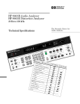
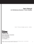
Solutions for Advancing Communications
MODEL MB-R OWNER’S MANUAL
Model MB-R
AVIATION BAND VHF RADIO
RECEIVER/TRANSMITTER
Base Station
(118.000-136.975 MHz)
www.mentorradio.com
Phone: 216-65-2315 Fax: 216-267-2915
MB-R-OM-03/11
INTRODUCTION
The Mentor Radio Model MB-R receives and transmits on up to six discrete channels in
the VHF aviation band between 118 and 136 Mhz. It is a base transceiver for air
carriers, airports, fixed-base operators, corporate flight departments, hospital
helipads, etc.
The unit is a separate M15 radio and a PA-25 power amplifier, which produces 10
watts of transmitter RF power. There is also a connection for connecting an aircraft
standard microphone using a 3/16” microphone plug.
Remote operation is an optional feature when you use a DB-15 plug. (See page 5 for
pin out)
The MB-R uses a switching power supply that allows the unit to operate from any
input voltage from 88-264 volts AC, 50/60 Hz power line. Power cords are available
for nearly any country in the world. A built in fuse is included inside a tray at the
power plug module on the rear panel. (Spare fuse included)
CIRCUIT DESCRIPTION
The receiver is a single-conversion super-heterodyne with four varactor-tracked RF
tuned circuits and dual-gate MOSFET transistors in the RF amplifier and mixer stages.
The local oscillator uses 3rd overtone crystals, and is followed by a MOSFET frequency
tripler stage. Receiver selectivity is primarily determined by a six-pole 10.7 MHz
crystal filter connected between the mixer and I.F. amplifier. The latter consists of
two cascade integrated circuit amplifier stages. Automatic gain control is applied to
the RF amplifier and the first I.F. amplifier stages.
A conventional diode detector is followed by a noise limiter, audio amplifier, squelch
“gate” and an integrated circuit audio power amplifier capable of delivering 4.5 watts
of audio power into a 4-ohm speaker. The transmitter oscillator also uses the 3rd
overtone crystals, followed by varactor tracked MOSFET tripler and buffer amplifiers.
Three un-tuned broadband stages boost the transmitter carrier power to
approximately 1 watt. Amplitude modulation is applied to the last two stages, the
"driver" and “final” amplifiers. The output from the M15 radio is applied to the PA-25
power amplifier that boosts the RF power up to 10 watts at the antenna connector.
The transmitter signal passes through a 7-element Chebychef low-pass harmonic
filter, which also contains two PIN diodes functioning as a T-R switch. The
transmitter modulator is separate from the receiver audio amplifier, and includes an
audio AGC amplifier that automatically adjusts for variations in operator “microphone
technique”. This circuit also prevents over modulation.
www.mentorradio.com
Phone: 216-65-2315 Fax: 216-267-2915
MB-R-OM-03/11
INSTALLATION
Select a desk, counter, shelf or table top on which to place the Model MB-R,
convenient to the operator but inaccessible to unauthorized persons. Allow several
inches of space behind and above the unit for air circulation; this is especially
important if heavy use is anticipated. Plug the line cord into a properly grounded
standard 3-wire electrical outlet. If an extension cord is needed, a 3-wire type should
be used. For operation outside of North America, an appropriate line cord must be
used.
The performance of both the receiver and transmitter is affected considerably by the
antenna and coaxial cable installation. For greatest range in all directions, the
antenna should be as high as practical, consistent with regulations concerning heights
of structures near the airport. If possible, the antenna should be higher than nearby
buildings to prevent shielding or “shadowing”. Antenna height is especially important
for communications with lower altitude aircraft, or if there is higher terrain within
desired communications distances.
The antenna for the Model MB-R should be located well away from other
communications antennas, if at all possible. Strong nearby signals from transmitters
on other channels can block or interfere with reception in any radio receiver. If there
are other aviation band transmitters and antennas on the airport, the minimum
recommended distances between these and the MB-R antenna depend on the
frequency separations, and are as follows:
Frequency Separation
Distance Between Antennas
less than 0.5 MHz
0.5 to 2 Mhz
2 to 5 Mhz
over 5 Mhz
0.5 miles (800 meters)
1000 ft. (300 meters)
500 ft. (150 meters)
300 ft. (100 meters)
If it is impossible to locate the MB-R’s antenna sufficiently far from other antennas,
and interference results, consult with Mentor Radio.
The coaxial cable (“coax”) connecting the antenna to the Model MB-R causes signal
attenuation proportional to its length in both the receive and transmit modes,
therefore a short cable is desirable. This factor often conflicts with the need to
locate the antenna high, away from structures and distant from other antennas. For
longer cables, coax types with lower signal loss should be used. Type RG-58 coax is
suitable for lengths up to 50 feet (15 meters). Type RG-8, or similar, can be used for
lengths to 150 feet (45 meters). For more than 150 feet, consult with Mentor Radio
about very low loss cables.
Low loss coaxial cable offers the lowest attenuation but are stiffer and therefore
harder to work with and install. For lengths that exceed 150 feet (50 meters),
consider remote operation.
www.mentorradio.com
Phone: 216-65-2315 Fax: 216-267-2915
MB-R-OM-03/11
The coaxial cable should be terminated at the radio end by an “N” type connector.
The connector should be installed by a person skilled in this operation. This
connector plugs into the mating connector (type “N”) on the rear of the MB-R. Be
sure to turn the ring with the internal threads CW until the connection is firmly made.
At the antenna end, if there is no similar connector, any unshielded center lead
should be no longer than 2 inches (5 cm.) A suitable adapter is required if a different
style antenna coax cable connector is used.
A number of acceptable microphone choices exist. Whether a handheld aircraft style
or a table or desk “dispatchers” style, a transistorized dynamic microphone element
is much preferred over the older carbon type elements that have poorer performance
and shorter lives. Many readily available microphones, such as a “condenser”, unamplified dynamic and ceramic types, will not work with the Model MB-R. The
microphone plug must be of the 3/16 inch diameter, 2-circuit type, as commonly used
in aircraft. The microphone plug should be inserted completely and firmly into the
microphone jack at the bottom right of the front panel.
If the Model MB-R will be operated remotely, refer to the MB-R assembly instructions
section.
www.mentorradio.com
Phone: 216-65-2315 Fax: 216-267-2915
MB-R-OM-03/11
MB-R ASSEMBLY/INSTALLATION
Assembly required before first use. Remove all packing material. Connect UHF
connector and power harness as shown.
MB-R Rear View
Antenna Connector
Connect the UHF
connector to rear
panel receptacle
as shown.
Connect power harness to rear
panel receptacles as shown.
Optionally connect remote cable
if provided.
Power Switch
Power Input Plug
(Fuse in tray)
REMOTE INTERFACE (DB-15)
Pin
1
2
3-4-5-6
7-8
9
15
Function
Mic PTT
Mic Audio
Ground
Audio, 4 ohm output
Audio, 500 ohm output
14VDC
Wire Color
Gray
Violet
Black
Green
Blue
Yellow
POWER PLUG (9 PIN)
Pin
1
2
3-4
5
6
7
8
Function
+13.8VDC
Speaker Audio
Ground
Audio, 500 ohm output
Audio, 4 ohm output
Remote Mic Audio In
Remote PTT
Wire Color
Red
Green
Black
Green/White
Blue
Violet
Gray
www.mentorradio.com
Phone: 216-65-2315 Fax: 216-267-2915
MB-R-OM-03/11
OPERATION
The Model MB-R is turned on and off by the rocker switch near the lower left rear
corner on the base. The volume control knob (marked VOL) adjusts speaker loudness
to the level preferred by the operator. The volume control may have a built-in, onoff switch. THE VOLUME CONTROL SWITCH SHOULD BE LEFT ON AT ALL TIMES.
Turn the unit on and off using the switch in the rear of the unit. The volume control
does not affect transmitter operation.
The squelch control (marked SQ) allows the operator to eliminate undesirable
receiver background noise when no signal is being received. Turning the knob
(marked SQ) fully counterclockwise “unsquelches” the receiver, allowing background
noise and very weak signals to be heard. Some operators may prefer to leave the
receiver unsquelched at all times. For those who prefer to use the squelch, periodic
unsquelching can serve as a receiver test, since a large reduction in background noise
might indicate receiver malfunction. To squelch the background noise, rotate the SQ
control clockwise only as far as necessary to just stop the noise.
Further rotation may result in not hearing more distant aircraft. There may be some
circumstances in which an operator does not wish to hear more distant aircraft, such
as, when such aircraft are communicating with a different ground station. In this
situation, the control may be rotated fully clockwise. The squelch control does not
affect transmitter operation.
If the Model MB-R has more than one channel, use the rotary channel switch on the
front panel to select the desired channel. Transmit and receive frequencies are
switched simultaneously. Changing the switch position connects a different pair of
crystals (one each for receiving and transmitting) and re-adjusts all tuned circuits for
the new channel. There may be small channel-to-channel variations in the receiver
sensitivity (as may be indicated by the speaker noise level) but this will not affect
communications significantly. In case of a communications problem, check that the
channel frequency selector switch has not been inadvertently changed to a different
channel.
An aviation type, noise-canceling microphone is recommended. To transmit, press
the push-to-talk (PTT) switch on the microphone. Hold the microphone close (1/4
inch or 1/2 cm) to your mouth and speak directly into the center of the microphone’s
acoustical opening, at a moderate voice level.
While the MB-R’s audio leveling circuits compensate for variations in microphone
output, “microphone technique” is extremely important for good clear transmissions.
Aviation microphones are purposely designed to be highly directive and are very
sensitive to the distance from the speaker’s mouth primarily to reduce pick-up of
background noise. It is impossible to overemphasize the importance of holding these
microphones close to the mouth and speaking clearly.
www.mentorradio.com
Phone: 216-65-2315 Fax: 216-267-2915
MB-R-OM-03/11
MICROPHONE TECHNIQUE
1.
2.
3.
Hold microphone close to mouth (1/4 inch or 1/2 cm)
Enunciate clearly
Speak with average loudness-not softly (but don’t shout)
If a non-noise canceling pedestal (dispatcher’s) microphone is used, it is not as
essential to hold the microphone close to the mouth. These microphones will pick up
more background and room noise, including the voices of other persons talking, radios
playing, etc.
On the front panel a red LED lights when transmitting. The MB-R includes a
transmitter timeout circuit. This protects the unit from unintended non-stop
transmission and also frees the channel in the event of a “stuck-mic”. The transmit
timeout will shut down the transmitter after approximately 30 seconds of continuous
transmission. The unit will not transmit again until after the “PTT” line is released
and keyed again. During this time, the unit’s transmit LED will remain turned off.
LIMITED WARRANTY
Your Mentor Radio, LLC equipment is warranted to the original consumer purchaser
only, for one full year, to be free from defects in materials and workmanship under
normal use. This warranty does not include damage to the product resulting from
accident or misuse. This warranty will not be effective unless you submit a
Warranty Registration online at www.mentorradio.com .
If the equipment should become defective within the warranty period, we will elect
to repair or replace it, without charge, if returned, postage prepaid, to the address
shown below. We are not liable for defects or damages caused by the use of
unauthorized replacement parts and/or service.
ALL IMPLIED WARRANTIES, INCLUDING THE IMPLIED WARRANTIES OF
MERCHANTABILITY AND FITTNESS FOR A PARTICULAR PURPOSE, ARE LIMITED IN
DURATION TO ONE YEAR. Some states do not allow limitations on how long an
implied warranty lasts, so the above limitations may not apply to you.
MENTOR RADIO, LLC., BECAUSE OF LACK OF CONTROL OVER THE CONDITIONS OF USE
OF THIS EQUIPMENT, IS NOT LIABLE FOR INCIDENTAL OR CONSEQUENTIAL DAMAGES.
ANY RECOVERY MAY NOT BE GREATER THAN THE PURCHASE PRICE PAID FOR THE
EQUIPMENT. Some states do not allow the exclusion or limitation of incidental or
consequential damages, so the above may not apply to you. This warranty gives
you specific legal rights, and you may also have other rights which vary from state
to state.
www.mentorradio.com
Phone: 216-65-2315 Fax: 216-267-2915
MB-R-OM-03/11