1
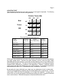
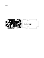
Model 805
DTMF Microphone
Operation and Maintenance Manual
01100750 Revision B2
CES WIRELESS TECHNOLOGIES
931-218 South Semoran Blvd.
Winter Park, Florida 32792
(407) 679-9440
June 6, 1994
Page 1
INTRODUCTION
Your new CES Model 805 Universal DTMF Encoder Microphone is designed to provide
superior and trouble free service. The 805 microphone can be used to dial DTMF
telephone numbers from a mobile radio, in conjunction with a base station equipped
with a telephone interconnect system.
Model 805 features include:
n
Automatic transmitter keying
n
Automatic microphone muting while transmitting DTMF
n
Reliable all metal keyboard switches
n
Audible sidetone for verifying proper tone entry
n
Universal audio input matching allowing operation with any radio
n
Oversized twelve-key backlit silicon rubber keypad
n
High-impact, weighted, and ergonomically designed case for maximum durability
n
Integrated tactile PTT switch and case seal to exclude dust and moisture
n
Tone burst or continuous DTMF tone operation
n
Long-life durable coil cord
The Model 805 is available with the following options:
n
Compatible mating connector installed for most popular two-way mobile radios.
Contact your CES sales representative, dealer, or distributor about your
requirement.
n
CTCSS Off-Hook Monitor logic for both open-circuit and closed circuit.
Page 2
INSTALLATION
The 805 Microphone requires 9VDC to 18VDC as a power source. If your 805 was
shipped with a factory installed connector, then refer to the Application Note that is
included, if any, for further instructions on modification of the radio to route this power
source to the radio microphone connector jack. Some radio models have this power
source already available and no modification is necessary. If your 805 was shipped
with no connector installed, refer to Table 1. and wire a connector that mates with the
radio microphone jack. Also refer to the radio service manual and schematic diagram
for the appropriate connector pin number for each function.
Table 1. - 805 Microphone Wiring Connections
Cable Conductor
Function
Blue
Red
White
Black
Shield
Yellow
+12 VDC
PTT (Push-To-Talk)
TX Audio Input
CTCSS Monitor Hang Up
Audio Ground
Power Ground
Microphone Power Source
Some transceivers will require a modification to bring a switched +9 to +18 VDC source voltage
from the radio power switch or power regulator. This modification can easily be performed by a
two-way radio technician. On most transceivers, a 'spare' or otherwise unused pin on the
microphone jack is often available, such as a handset audio function. If using a pin that already
has a functional purpose, ensure that this connection path or wire is disconnected from the
microphone connector before routing the B+ source voltage for the 805 microphone. If the
source pin to be used has a series resistor of more than 22 ohms, then bypass this resistor.
After wiring the microphone connector, verify proper connections before applying power. Use an
ohmmeter between the +12 VDC connection and ground(s) with and without the microphone
connected. The resistance reading should not change appreciatively, and in particular should not
show a low resistance reading with the microphone connected.
If presence of alternator whine or other vehicular noise is apparent upon placing the 805 into
service, remove the jumper JPR2 on the 805 printed circuit board. Refer to the Component
Layout illustration for location of this jumper.
Note: The 805 Series DTMF Microphones have been engineered to provide optimum
performance with virtually all land mobile radio transceivers. However, if using the 805
with a radio that does not incorporate pre-emphasis (sometimes this is done in the
original radio microphone) the resulting transmitted modulation will sound 'bassy'. If this
is the case, then change the 805 audio output coupling capacitor C10 to .001 uF. If
difficulty remains, contact CES Customer Service.
Page 3
INSTALLATION - continued
Continuous Tone Coded Squelch
The 805 provides CTCSS or other tone decoder monitor or disable as a logical function
that goes low or to ground whenever the microphone is placed on a grounded hang up
clip. For applications that require a logical low or ground when the microphone is
removed from the grounded hang up clip, contact the CES Sales Department.
When installing the 805 microphone, ensure that the microphone hang up clip is
properly grounded to the vehicle chassis (add a ground wire if necessary) if using
CTCSS or other Tone Decoder hang up logic in the radio.
Combined TX Audio and Other Functions
For transceivers that require that the PTT signal is electrically sent from the
microphone on the same wire connection as microphone audio, then install an
appropriate resistor across jumper JPR3 on the 805 printed circuit board. Refer to the
Component Layout illustration for location of this jumper. For the value of this resistor,
refer to the original microphone circuit schematic diagram.
For transceivers that require that CTCSS or other tone decoder hang function and
microphone audio be sent on the same wire connection to the radio, install a resistor at
R15 on the 805 printed circuit board. Refer to the Component Layout illustration for
location of this jumper.
On most radio models manufactured by Standard
Communications the value of this resistor will be 8.2K ohms.
MICROPHONE OUTPUT LEVEL MATCHING
Before beginning to set output levels, consideration must be given to the type of
microphone the radio uses and 805 jumper JPR1 (Refer to the Component Layout
illustration for location of this jumper):
Generally, JPR1 should be IN for radios using low impedance dynamic nonpreamplified microphones.
Jumper JPR1 should be removed for radios that use microphones with an internal
preamplifier.
The 805 is shipped with jumper JPR1 in place, except for certain 805 application
models where the jumper may already be removed for the specific radio type as
ordered.
VOICE AUDIO OUTPUT ADJUSTMENT
Set up a communications service monitor on the transmitter frequency of a desired test
or operational channel programmed into the radio. The use of an RF dummy load is
recommended. Adjust the microphone potentiometer RV2 (accessible through the
lower opening in the rear of the 805) while speaking in a normal voice so that the voice
peaks just go into modulation limiting as observed on the service monitor oscilloscope.
If the service monitor does not have an oscilloscope display, then it is suggested that
the 'demod' output be connected to an oscilloscope.
Page 4
INSTALLATION - continued
DTMF TONE OUTPUT LEVEL
With the service monitor set up as in the previous test: press a DTMF key on the 805
and adjust potentiometer RV1 (accessible through the upper opening) for 2/3 of the
level that modulation limiting occurs as observed on the service monitor. For instance,
if modulation limiting occurs at 5.0 KHZ, then set RV1 for a DTMF tone modulation of
3.3 KHz. If CTCSS tone is also being transmitted at the same time, set RV1 for a
combined CTCSS + DTMF deviation of 4.0 KHz. Verify that the DTMF tones are not
clipped or distorted as observed on the service monitor oscilloscope.
For other system deviation limits, as in 2.5 KHz systems, utilize the same technique
and 2/3 ratio in adjusting the DTMF and voice modulation levels .
Location of Adjustments
Once the DTMF and voice modulation adjustments have been completed, remove the backing
from the rear panel label included and place the label over the potentiometer adjustment access
area.
Page 5
ADJUSTING TWIST
The microphone generates two tones when any key on the keypad is depressed. The following
table illustrates the row and column tones generated:
Column Tones (Hz)
Row
Tones
(Hz)
1209
1336
1477
697
1
2
3
770
4
5
6
852
7
8
9
941
*
0
#
The actual frequencies generated are:
Keypad
Location
Reference
Tone (Hz)
Actual
Tone Output (Hz)
Percent
Deviation
Row Tone 1
697
699.1
+0.30
Row Tone 2
770
766.2
-0.49
Row Tone 3
852
847.4
-0.54
Row Tone 4
941
948.0
+0.74
Column Tone 1
1209
1331.7
+0.57
Column Tone 2
1336
1331.7
-0.32
Column Tone 3
1477
1471.9
-0.35
DTMF twist is the ratio between the levels of the column tones and the row tones generated by
any single keypad button. Because the higher frequency (column) tones are more readily
attenuated than the lower frequency (row) tones, the high frequency tones of any DTMF pair are
sent at a slightly higher level. The ratio of column/row tones is factory set to telephone industry
standards and no adjustment is needed for most applications. However, if particular systems
require levels other than the standard ratio, they can be adjusted. To increase the column/row
ratio decrease the value of C4. To decrease the ratio, increase the value of C4.
By generating the tones individually as a single tone, any adjustment of twist is made easier.
This can be accomplished by temporarily the circuit board plating from U3 and ground. The burst
mode jumper JPR4 must also be temporarily cut for single tone operation. A single row or
column tone can now be generated by simultaneously pressing two keys in respective horizontal
row or vertical column. Reinstall the jumpers as they were before when done.
Page 6
JPR1
C6
C7
R25
JPR4
R12
Q3
CR5
U1
C15
CR6
C19
CR2
R16
CR3
C3
R1
R21
U4
C22
JPR2
P2
R23
R14
Q1
S1
L1
R22
R9
R20
J3
R10
È
U5
C8
C18
R27
R28
Q4
Q2
U6
C14
È
R19
R3
C9
C5
R8
R24
U2
C2
CR1
C16
C4
C20
R17
C10
U3
C13
C23
R29
R4
R5
È
Q5
R7
C11
C17
R11
JPR3
R2
R18
R6
JPR5
R13
C21
R30
È
CR4
C12
R26
RV2
RV1
Y1
<
P1
R15
Page 7
DTMF BURST TONE MODE
Model 805 microphones are shipped with the "Continuous Tone" mode enabled. To
change to a "Burst Tone" mode, remove jumper JPR4 on the 805 printed circuit board.
Refer to the Component Layout illustration for location of this jumper. When the 805 is
in the Burst Tone mode, each time a key is depressed a burst of the applicable DTMF
tone is generated for a period of 150 milliseconds, independent of how long the user
holds the key depressed. This feature is provided, as some systems require this type
of DTMF signalling.
CIRCUIT DESCRIPTION
Each time a key is depressed on the keypad the normally low output of U3 goes high,
forward biasing CR2 and causing C19 to charge. The charge on C19 causes both
inputs of U1C pins 8 and 9 to go high resulting in the output on pin 10 to go low. A low
on either input of U1A results in a high output. With input pin 1 low, the output pin 3
will be high. This high is routed to pin 5 of U1B. When pins 5 and 6 of U1B are high,
the output pin 4 of U1B will be low. This is tied to pin 2 of U1A. With a low on both
outputs, pin 3 of U1A will stay high and the circuit is now latched, causing Q1 to
conduct and turning on the sidetone audio amplifier. Pin 3 of U1A also causes CR5 to
be forward biased which in turn causes Q2 and Q3 to conduct and automatically key
the transmitter and illuminating the PTT LED. C19 will keep the circuit latched for
approximately 1.5 seconds after each key has been pressed. This time delay allows
the next key to be pressed before the transmitter is dropped.
With jumper JPR4 in place, the tone generated will be a tone burst of approximately
150 ms per digit, regardless of how long the key is depressed. With this jumper
removed, the tone will be sent for the duration of time that the key is depressed.
To adjust the length of the tone burst, change the value of R16 (270K). A higher
resistance will result in a longer tone burst length.
The tone output goes from pin 16 of U3 through RV1 (the tone level adjustment), R1
and C5 to the level matching point at the junction of R8 and R24. The audio is then
brought to the microphone output amplifier U4B pin 6. When a high level of audio
output is required, jumper JPR1 is removed. This allows U3 to operate without
negative feedback and raises the available audio level. RV1 adjusts the tone deviation
level. C4 can be increased or decreased in value to change the column/row tone radio.
When the PTT switch is pressed, manual keying with voice audio is activated. The
PTT switch S1 connects R2 to +5VDC which causes Q4 to turn on, activating the
microphone audio path through U4A. Pressing the PTT switch also causes CR6 to be
forward biased that in turn causes Q2 and Q3 to conduct, automatically keying the
transmitter and illuminating the PTT LED.
Page 8
Model 805 Parts List
Reference
Description
CES Part #
Reference
Description
CES Part #
C1
C2 C3 C8
C9 C17 C21
C4
C5
C6 C7 C13
C10
C11
C12 C15
C14 C19
C16
C18
C20
C22
C23*
Capacitor 10 uf
CE106
Capacitor .1 uf 50V
Capacitor 470 pf
Capacitor .01 uf
Capacitor 220 pf
Capacitor 2.2 uf NP
Capacitor 22 pf
Capacitor 1 uf
Capacitor 10 pf
Capacitor 1500 pf
Capacitor 100 uf
Capacitor 2700 pf
Capacitor .047 uf
Capacitor .001 uf
CM.1
CM471
CM.01
CM221
CE2.2NP
CM220
CT1
CT10
CM152
CE107
CM272
CM.047
CM.01
R16
R17
R18
R20
R21 R26
R22 R23 R24
R29*
R15* R30*
Resistor 270K
Resistor 200K
Resistor 1.5K
Resistor 2.2K
Resistor 560 ohm
Resistor 8.2K
Resistor 470 ohm
Resistor 10K
RC224
RC204
RC152
RC222
RC561
RC8.2K
RC183
RC10K
RV1
RV2
Potentiometer 100K
Potentiometer 10K
RV100K
RV103
S1
Switch PTT
MIC04-R
CR1
CR2 CR3
CR5 CR6
CR4
Diode 1N5248
D5248
Diode 1N914
Diode 1N4749
D914
D4749
U1
U2
U3
U4
U5 U6
IC 4011
IC TDA7050
IC S2559E
IC TL062
IC 5V Regulator
U4011
U7050
U2559
U062
U78L05
Y1
Crystal 3.579 Mhz
XTAL4
J2
2-Pin Connector
CON53
non-ref items
L1
Choke 10 mH
CHOKE-2
P1
P2
Connector 14-pin
Connector 6-pin
CON02
CON54
Q1
Q2
Q3 Q5
Q4
Transistor MPSA13
FET VN10KM
Transistor 2N2222
JFET J201
QA13
QVN10
Q2222
QJ201
R1 R4
R2 R3
R5 R19
R6 R25 R27
R7
R8 R9 R28
R10
R11
R12 R14
R13
Resistor 150K
Resistor 47K
Resistor 470
Resistor 47K
Resistor 330
Resistor 100K
Resistor 18 ohm
Resistor 68K
Resistor 10K
Resistor 3.9K
RC154
RC473
RC471
RC473
RC331
RC104
RC18R
RC682
RC10K
RC392
Front Case Half
Rear Case Half
H/Up Button Strap
Weight, 80 grams
Hang Up Button
Screw, H/Up Button
Rubber Gasket
PTT Button Plate
Case Screw
Silicon Keypad
Bezel
PTT Button Spring
Electric Microphone
Speaker 1.5" 8 ohm
PTT LED Red
Rear Label, 805
Microphone Cord
Flex Strip
MIC04-A
MIC04-B
MIC04-C
MIC04-D
MIC04-E
MIC04-F
MIC04-G
MIC04-H
MIC04-K
MIC04-T
MIC04-U
MIC04-N
MIC04-Q
MIC04-S
LED4
LABEL016
CRDMIC-2**
FLEX1
Notes: * These components apply only to optional 805 circuit functions such as CTCSS Inverter, etc.
**Microphone cord part number shown is for anunterminated coil cord assembly (no connector).
Limited Warranty
CES WIRELESS TECHNOLOGIES (CES) warrants this product to be free of defect in
material and workmanship and extends this warranty under intended use and normal
service conditions to the original owner for a period of one year from the date of
purchase.
This warranty does not apply to any product that has been subjected to repairs or
alteration not authorized by CES, or for any product that has been damaged due to
accident, abuse, neglect, vandalism, loss, unreasonable use, improper installations,
lightning, fire, or water damage.
The obligations of CES are limited to repairing or replacing, at the option of CES, any
product or component that is returned to the factory all transportation charges prepaid,
accompanied by proof of purchase and which examination reveals to have been
defective within the warranty period stated above. CES does not assume, nor is any
person authorized to assume for it, any obligation other than that stated herein.
Any implied warranties, including but not limited to fitness for a particular purpose, are
limited in duration for the above one year period. CES shall not be liable under this
warranty, or any implied warranty, for the loss of use of the product or for any other
consequential loss or damage incurred by the purchaser.
Some states do not allow the exclusion or limitation of implied warranties or
consequential damages and so the above exclusions or limitations may not apply. This
warranty gives you special legal rights and you may have other rights that vary from
state to state.


![Trace Elliot V4[1]](http://vs1.manualzilla.com/store/data/006017218_1-da9c5d9940e3b4825dbcd5847480f1a7-150x150.png)