1
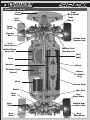
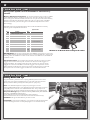
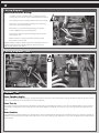
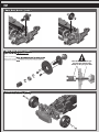
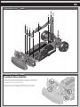
12/12
2
:: Introduction
Thank you for purchasing this Team Associated Qualifier Series product. This manual contains
instructions and tips for maintaining your new APEX RTR. Please take a moment to read through it
and familiarize yourself with these steps as they will help you to understand each component’s
function and show you some tips for getting the most out of your APEX RTR. We are continually
changing and improving our designs; therefore, actual parts may appear slightly different than the
illustrations.
For more information, scan the QR code to the right for videos and
tutorials on the APEX RTR!
http://www.teamassociated.com/cars_and_trucks/Apex/RTR
:: APEX Platform Features
• Fully assembled, shaft drive 4wd Touring car with gear differentials
• Water RESISTANT XP SC500-BL brushless electronic speed control with Deans® Ultra Plug®
(2S-3S LiPo compatible)
• Reedy WolfPack 7-cell NiMH Battery w/Deans® Ultra Plug® Connector
• Powerful Reedy 3300kV 540 brushless motor
• XP 2.4Ghz Radio system with XP metal gear steering servo
• Composite modular chassis accepts NiMH or LiPo type batteries
• 10 spoke Touring car wheels with high grip racing tires
• Factory-finished touring car race body
• Fluid filled adjustable shock absorbers
• All steel CVA drive axles front and rear
• All metric hardware and ball bearings throughout
• Sealed metal gear differentials
:: Additional Items Needed
Your APEX RTR requires the following items to complete your kit:
• Transmitter batteries (x6 AA’s) (#302, 303 AA batteries recommended)
• NiMH Battery charger (peak detection charger recommended) (AE #604)
-OR- Wall charger (#29154) • Needle nose pliers • Hobby knife
• Reamer/hole punch • Ride Height Gauge (#1450 recommended)
:: Other Helpful Items
• Silicone Shock Fluid / Differential Fluid (Refer to catalog for complete listings)
• Body Scissors (AE Part # 1737)
• FT Threadlock (#1596)
• FT Hex Wrenches (AE Part # 1541, 1655)
• Multi Tool (AE Part #7494)
• FT Nut Drivers (AE Part #1561, 1663-1668)
• Calipers or a Precision Ruler
• FT Turnbuckle Wrench (#1112)
• Soldering Iron
• Green Slime shock lube (AE Part # 1105)
• Wire cutters
Associated Electrics, Inc.
26021 Commercentre Dr.
Lake Forest, CA 92630
Customer Service
Tel: 949.544.7500
Fax: 949.544.7501
http://www.TeamAssociated.com · http://www.RC10.com · http://twitter.com/Team_Associated · http://bit.ly/AEonFacebook
3
:: Table of Contents
1....................Cover
2....................Introduction
3....................Table of Contents
4....................Blueprint of the APEX
5-7................Quick Start Guide
12-14..........Front Diff Access
14.................Diff Maintenance
14-15..........Shock Maintenance
16.................Motor Manual
17................. ESC Manual
18-27..........Catalog
8....................Electronics Wiring /
Camber & Toe Settings
28................1:1 Hardware “Fold Out”
9...................Gear Mesh & Ride Height
29................Notes
10-12..........Spur Gear Access / Rear Diff
Access
30................Trouble Shooting
:: Notes
!
This symbols indicates a
special note or instruction
in the manual.
Associated Electrics, Inc.
26021 Commercentre Dr.
Lake Forest, CA 92630
There is a 1:1 hardware foldout page in the back
of the manual. To check the size of a part, line
up your hardare with the correct drawing until
you find the exact size. Each part in the foldout
has a number assigned to it for ordering
replacement parts.
Customer Service
Tel: 949.544.7500
Fax: 949.544.7501
http://www.TeamAssociated.com · http://www.RC10.com · http://twitter.com/Team_Associated · http://bit.ly/AEonFacebook
4
:: Blueprint of the APEX
Front
Bumper
Front
Body Mount
Front
Arm
Front
Shock
Caster
Block
Steering
Block
Molded Front
Camber Link
Front
Shock Tower
Molded Front
Servo Link
Molded Front
Steering Link
Drive
Shaft
Servo
Receiver
Chassis
Electronic Speed
Control
Battery
w/ Deans®
Plug
Motor
Battery Strap
Pinion
Rear
Arm
Rear
Hub
Rear
Shock
Spur Gear
Rear
Shock Tower
Molded Rear
Camber Link
Rear
Body Mount
5
:: Quick Start Guide
Battery Charging Steps and Safety:
NiMH Wall Charger: (Part #29154 Wall Charger AC 120V 350MaH)
NiMH Quick Charger: (Part #610 Reedy 447-S AC/DC 4-7 Cell Peak Prediction
NiMH/NiCd Charger)
Remove the battery from the vehicle before
charging. Be sure to select the correct
charging mode for the type of battery you
are charging.
NEVER leave the battery unattended while
charging!
NiMH: NiMH batteries (nickel-metal hydride)
are high current rechargeable batteries.
If you use a peak detection charger, make sure
it is designed for NiMH batteries!
Wall Charger
:: Quick Start Guide - (cont.)
Battery Installation:
1.
2.
3.
Install the battery with the battery wires directed
towards the front of the vehicle.
Insert the battery strap onto the battery post
screws.
Secure battery strap with body clips.
1
You may move the foam pad to either the front or the rear
of the battery compartment to adjust the weight balance
of the vehicle.
:: Quick Start Guide - (cont.)
2
3
Peak Detection
Quick Charger
6
:: Quick Start Guide - (cont.)
Change the speed control to NiMH or LiPo battery
modes.
Battery Management System - A choice of either LiPo mode or NiMH
mode adjusts the low voltage cutoff point. This is critically important
when using LiPo batteries that should not, for performance and safety
reasons, be discharged below 3.0V per cell. In LiPo mode, the ESC
detects whether you are using 2 or 3 cells and adjusts the cutoff
accordingly.
The ESC can be toggled between LiPo mode and NiMH mode by
following the steps outlined below.
Signal From ESC
Step #
Procedure
Audio
LED
bi-bi
2 green flash/ green static (LiPo Mode)
Battery Management System
1
Power ON Transmitter
2
Trigger position to maximum brake (hold)
3
Power On ESC
4
Throttle position to neutral
5
Power OFF ESC, then transmitter
6
Power ON transmitter, then ESC
or red static (NiMH Mode)
Push for
Brake
melody
3 green flash, 2 red flash,
bibi-bibi
green static or red static
Pull for Throttle
IMPORTANT! When the transmitter and ESC are turned on, the color
of the ESC LED at neutral indicates which mode the ESC is in. When the
LED is green, the ESC is in LiPo mode. When the LED is red, the ESC is
in NiMH mode.
Vehicle Operation - To operate the vehicle, pull back on the throttle
trigger to move forward, push forward on the throttle trigger to
engage brakes. To engage reverse, push forward on the throttle
trigger to maximum brakes. Hold the trigger in this position for at
least 0.5 seconds before returning the throttle trigger to neutral.
Now push the throttle trigger forward to reverse the vehicle.
:: Quick Start Guide - (cont.)
Battery Notes and Tip:
Plug the battery in as shown. Unplug battery when not in use!
There are two types of batteries you can use with this vehicle.
NiMH (nickel-metal hydride) and LiPo (lithium polymer).
LiPo: LiPo batteries (lithium polymer) are high current
rechargeable batteries. LiPo batteries offer extended run time
and peak performance over NiMH batteries. They require a
peak detection charger designed specifically for LiPo batteries.
LiPo/LiFe Charger: (Part # 604 - Reedy 526-S AC/DC 2S-6S
Cell LiPo/LiFe Balance Charger)
These batteries require specal care and handling.
LiPo batteries are recommended for advanced users only!
ALWAYS charge a LiPo battery in LiPo mode.
CAUTION! If using a LiPo battery, you need to change the speed
control settings to LiPo mode (see page 17 for instructions).
Neutral
Throttle set to Neutral when turning on the radio !
7
:: Quick Start Guide - (cont.)
Radio System Tuning and Controls:
4
RULE: Transmitter on First/Vehicle on Second, Vehicle
off First/ Transmitter off Last!
1)
2)
3)
4)
Slide the battery cover in the direction shown to
remove cover.
Install six (6) alkaline or rechargeable AA size
batteries into the battery holder.
Slide the battery cover back into place making
sure it is completely closed and secore.
Turn the power ON. If the power indicator LED
fails to light, check the batteries for insufficient
contact or incorrect polarity.
While pressing this part
1
On/Off Switch
Battery cell (x6)
2
3
Battery cover
:: Quick Start Guide - (cont.)
Radio System Tuning and Controls:
DO NOT hold the trigger when turning on the radio.
If using optional battery for transmitter, be sure to plug
it in correctly. Plugging in a battery backwards can
cause damage.
Left
Right
Refer to Radio owners manual for more in-depth
instructions on radio operation and functions.
Push for
Brake
Pull for Throttle
Neutral
Throttle set to Neutral when turning on the radio !
:: Quick Start Guide - (cont.)
Adjust steering
trim so front
wheels point
straight.
Install body and body clips.
Ready to go!
8
:: Wiring Diagrams
Motor and Receiver Wiring:
1. 2.
If motor runs in reverse when you apply throttle, unplug any two of the motor wires and switch them.
Your Receiver has multiple channel ports for plugs.
Channel 1 - you should always plug your steering servo into this channel port.
Channel 2 - you should always plug your speed
control (ESC) into this channel port.
Channel 3 - Used for optional equipment such as fans, lights, ect...
Batt - Used for optional receiver battery pack.
Not used in this model.
1
Negative black wires on steering servo and speed control
plugs should face the outside edge of receiver where
channel markers are located.
:: Wiring Diagrams - (cont.)
2
:: Camber / Toe
Front Camber Angle:
A good starting camber setting is –2 degrees (where the top of the tires lean inwards). Positive camber, where the top
of the tire is leaning out, is typically not recommended.
Front Toe-In:
Zero degree toe-in (tires pointing straight forward) is a good starting setting. You can increase steering into corners
by adding 1-2 degrees of toe-out (front of tires point slightly outward). Front toe - in is not a typical tuning adjustment
used.
Rear Camber:
A good starting camber setting is –2 degrees. Use #1719 camber gauge (not included) to set your camber. Adding a
small amount of positive camber, where the top of the tire is leaning out, will tend to improve straight-line acceleration on
loose tracks.
9
:: Gear Mesh
Gear Mesh:
To correctly set your gear mesh, follow the steps below:
1. Remove the Chassis Brace. Loosen the set screw on the motor’s pinion gear. Slide the pinion on the motor shaft
until the gear face of the pinion is entirely aligned with the gear face of the spur gear (see diagram). Tighten the set
screw while ensuring it is aligned with the flat face on the motor shaft.
Pinion
Spur Gear
2. Loosen the motor clamp screw until the motor is able to move freely.
Rotate the motor as far as it can go towards the spur gear, ensuring that
the teeth of the pinion and the spur gear are interlocking. Slide the motor
back (approximately 0.5 mm), and tighten the motor clamp screw.
Proper gear mesh has been achieved when the teeth are meshing closely,
but the gears still have a small amount of clearance between them. If you hold
one gear, you should be able to rock the other gear back and forth a small
amount. If there is no clearance, your gear mesh is too tight and you should
readjust the motor again.
Pinion
:: Ride Height
Adjusting Ride Height:
Ride height is adjusted by adding and /or removing shock pre-load clips to the front
and rear shocks. Stock setting is approximately 4mm front and rear. Check the
ride height with the FT Ride Height Gauge (#1450). Raise or lower the ride height
with the shock clips as necessary and recheck.
Spur Gear
Front shock: 4mm
Rear shock: 4mm
7149
Shock
pre-load
clips
1mm
2mm
4mm
6mm
10
:: Spur Gear Access
:: Spur Gear Access - (cont.)
11
:: Spur Gear Access - (cont.)
Rear Shock Tower Removal:
Loosen the ball studs highlighted in order to
remove the shock tower with the shocks and
camber turnbuckles attached as one complete
piece.
Make sure you re-install the CVA bones into the diff
outdrives when re-installing the rear shock tower!
:: Spur Gear Access - (cont.)
12
:: Spur Gear Access - (cont.)
:: Spur Gear Access - (cont.)
Spur Gear Maintenance:
When accessing your spur gear, check for wear on the
teeth of the gear. The teeth should be nice and sharp.
Replace if necessary
:: Front Diff Access - (cont.)
!
Note the location of the spur
gear hub pin and the 4mm
E-Clips on the spur gear shaft
13
:: Front Diff Access - (cont.)
:: Front Diff Access - (cont.)
Front Shock Tower Removal:
Loosen the ball studs highlighted in order to remove the
shock tower with the shocks and camber turnbuckles
attached as one complete piece.
Make sure you re-install the CVA bones into the diff
outdrives when re-installing the front shock tower!
14
:: Front Diff Access - (cont.)
:: Diff Maintenance
Differential Maintenance:
Once you have removed the Diff gear, you can now drain
the existing diff fluid from the differential.
Stock Shock
Fluid Setting:
Check the diff gasket for wear or damage.
Replace if necessary
Front:
black grease
Fill the diff to the top of the cross pin with your choice of
diff fluids.
Rear:
black grease
Front Diff:
Dif
f
flui
d
Thicker oil will get less low speed steering and better acceleration out of turns.
Rear Diff:
Thicker oil will rotate less in the turns and accelerate
straight on power. Thinner oil will give more low speed
traction.
:: Shock Maintenance
15
:: Shock Maintenance - (cont.)
Bladder Installation
t
35w luid
ck f
Sho
Stock Shock
Fluid Setting:
Front: 35wt
Rear: 35wt
A
B
C
As you install the shock cap with the bladder, it will force
out any extra fluid. If you install the cap with the shaft
fully extended, you are running FULL REBOUND.This
means the shaft will fully rebound when compressed.
To run less rebound, unthread the cap 1-2 turns and
compress the shaft to the desired position and
re-tighten the cap with the shaft compressed.
Start with no rebound.
:: Shock Maintenance - (cont.)
Shock Maintenance:
If you need to only refill your shocks with oil, follow the steps
above only then move to the shock bleeding steps.
If your shocks leak from the bottom shock cap, follow all
shock maintenance sections.
Replace the inner O-Ring in the bottom cap, then begin the
shock oil filling and bleeding process.
:: Shock Maintenance - (cont.)
!
Shock Bleeding Steps:
1.
2.
3.
4.
5.
6.
7.
8.
9.
10.
Step 1-2
Step 3-4
Step 5
Step 6-8
Pull shock shaft down.
Fill shock body 3/4 full with silicone
shock fluid.
Slowly move the shock shaft up and
down to remove air from under the
piston.
Wait for bubbles to come to surface.
Fill shock body to top with silicone
shock fluid.
Place a drop of oil in the cap and on
cap threads.
Install cap and tighten completely.
Unscrew the cap 3/4 turns and tilt
the shock at a slight angle.
Slowly compress shaft all the way to
bleed excess silicone shock fluid and
air. You should see bubbles coming
out from under the cap. (use rag
around shock to catch excess fluid).
With the shaft compressed, tighten
the cap and re-check for pressure at
the top of the stroke. If there is still
pressure, repeat steps 3-9.
Some residual
Check for
shock
fluid may
pressure
appear from your
first few runs
around the shock
cap as a result of
bleeding.
Slow
w
Slo
Step 9-10
16
:: Motor Manual
540R
BRUSHLESS
MOTOR
• Connect the three leads exiting the motor to the
three motor leads from your Electronic Speed
Control (ESC). If the motor runs backwards
when giving it forward throttle, reverse any two
motor leads. The motor will now turn in the
desired direction.
• To clean your motor, lightly brush dirt away on
a regular basis paying particularly close attention
to the areas around the ball bearings. DO NOT
spray cleaners or solvents into the motor.
Caution
When switching to a higher voltage battery from a
lower one (to 11.1V from 7.4V, for example), a
change in gear ratio or a lower kV motor might be
necessary. Otherwise, the motor or ESC may
overheat and sustain permanent damage. Please
visit www.reedypower.com for the latest gear ratio
suggestions for your particular motor and vehicle.
Introduction
Congratulations on your purchase of Reedy’s
540R Brushless Motor. The latest brushless
motor technology along with the design and
engineering experience that is responsible for 28
World Championship titles has been incorporated
into its design.
Safety Precautions
This product is a sophisticated hobby product and
not a toy. It must be operated with caution and
common sense and requires some basic
mechanical ability. Failure to operate this product
in a safe and responsible manner could result in
injury or damage to the product or property. This
product is not intended to be used by children
without direct adult supervision. It is essential to
read and follow all instructions and warning found
in this manual prior to installation, set up, and use
in order for the product to operate properly and to
avoid damage or injury.
Due to its sensorless design, the Reedy 540R
Brushless Motor operates powerfully and
efficiently without complicated sensor harnesses.
This motor is perfectly suited for use with ESCs
that are designed to operate sensorless
brushless motors.
Please read the following before
installing and using your new motor.
Features
•
•
•
•
•
•
Oversized Precision Ball Bearings
High-Strength Rotor
Hardened Steel Shaft
Triple-Insulated Windings
Sensorless Operation
3.5mm Connectors
Precautions and Warnings
• Please read the instructions before installing
and operating your motor.
• Avoid over gearing by monitoring motor
temperature. Operating temperatures should
not exceed 80C (175F).
• Be sure to use the proper size motor mounting
screws.
• Do not over-tighten the motor mounting screws.
• Do not use a Schottky diode with this motor.
Installation and Maintenance
• Your motor should be installed using 3mm
screws with a length (generally 6mm or less)
that does not allow the screw to extend into the
motor more than 5mm. Otherwise, the screw
can damage the motor’s internal components.
• Do not over-tighten the motor mounting screws.
Doing so may strip the mounting hole threads.
Specifications
Model
540R 3300kV
540R 3900kV
540R 4900kV
540R 6100kV
Item No.
916
917
918
919
Cells
2-3 LiPo, 6-8 NiMH 2-3 LiPo, 4-8 NiMH 2-3 LiPo, 4-8 NiMH 2-3 LiPo, 4-8 NiM
RPM/Volt
3300
Dimensions
Shaft Diameter
3900
4900
6100
36x46mm
36x46mm
36x46mm
36x46mm
3.17mm
3.17mm
3.17mm
3.17mm
Max. Efficiency Current 10~40A
10~45A
10~50A
10~55A
Max. Surge Current
45A/60s
50A/60s
55A/60s
60A/60s
190g/6.7oz
190g/6.7oz
190g/6.7oz
190g/6.7oz
Internal Resistance
Weight
Warranty
Your motor is warranted to the original purchaser
for 90 days from the date of purchase, verified by
the sales receipt, against defects in material and
workmanship. Motors that have been mishandled,
abused, used incorrectly, used for an application
other than intended or damaged by the user are
not covered under warranty.
Associated Electrics Inc. is not liable for any loss
or damage, whether direct or indirect, incidental or
consequential, or from any special situation,
arising from the use, misuse, or abuse of this
product
17
:: ESC Manual
Throttle/Brake Calibration
Your new ESC must be calibrated before use. Before calibration, be sure to
set your radio’s throttle and brake EPAs to 100% and your throttle trim to
neutral. Then follow the steps outlined below.
Signal From ESC
Procedure
Battery Management System - A choice of either LiPo mode or NiMH mode
adjusts the low voltage cutoff point. This is critically important when using LiPo
batteries that should not, for performance and safety reasons, be discharged
below 3.0V per cell. In LiPo mode, the ESC detects whether you are using 2
or 3 cells and adjusts the cutoff accordingly.
The ESC can be toggled between LiPo and NiMH by following the steps
outlined below.
Signal From ESC
Audio
#29138
XP SC500-BL
Brushless ESC
bibibibibibi
Throttle trigger pos tion to neutral
bibi-bibi
Throttle trigger pos tion to maximum brake
bibi-bibi
Power OFF ESC, Power OFF transmitter
Once the calibration procedure is complete, turn on your transmitter, then
your ESC, and begin operating your vehicle. Note: If you choose to make
settings adjustments at this time, you can do so immediately after step #6
of the throttle calibration procedure.
Congratulations on your XP Brushless Electronic Speed Control (ESC)
purchase. The latest electronics technology along with the design and
engineering experience that is responsible for multiple World Championship
titles has been incorporated into its design.
Your ESC comes with pre-programmed default settings. But you can also
change the settings based on the type of vehicle and battery used as well
as personal performance preferences based on the track you are driving on
and your driving style.
Your XP Brushless ESC is water-resistant for maximum durability. Its light
and compact design allows for easy installation in most 1/10 vehicles.
Simple calibration and a wide variety of tuning options make this ESC perfect
for both casual enthusiast and racers. When paired with a Reedy Brushless
Motors, you create a potent combination of power and efficiency that brings
performance to a new level. More power and less maintenance elevate the
fun factor by increasing top speeds and reducing down time.
Drag Brake - Drag brake is the amount of braking achieved when the throttle
is returned to neutral. A setting of 0% means the vehicle will free wheel to a
stop while higher settings will stop the car faster. Please note that regardless
of the drag brake setting, you will still be able to use the brake trigger to
manually slow the car.
•
•
•
•
•
•
•
•
•
•
•
•
Adjustable LiPo Low-Voltage Cutoff
LiPo Cell Count Auto Detect
Reversible With Reverse Lockout
Fully Proportional Brakes
Adjustable Drag Brakes
Adjustable Throttle Profile
Hard Case with Aluminum Heat Sink
Water Resistant
Heavy Duty Silicone Wires
Deans® Ultra Plug® Connector
3.5mm Motor Connectors
Pre-Wired For Optional Cooling Fan
Specifications
Throttle Profile – This setting adjusts the power delivery of your ESC/motor
combination. The Very Soft setting can be used on loose or bumpy track to
reduce wheel spin while the Maximum setting works well when high traction is
available. Four settings provide options for any track condition.
Run Mode - This gives the option of using reverse or eliminating it completely
(for competition). With reverse activated, you will still have fully proportional
braking. To make settings adjustments, you must first follow the calibration
procedure. You will encounter a 5-second delay before entering step #1 of the
settings adjustment mode. All changes will be made using your transmitter’s
throttle trigger. Note: Once you enter the settings adjustment mode, the ESC
will scroll through all options. If you fail to choose a setting, the ESC will keep
the previously saved setting.
For example, if you want to change the throttle profile from Soft to Standard,
enter the settings mode. You will encounter the Drag Brake mode first at
which time you can let the ESC scroll through the choices (the previously
saved setting will be kept) until you reach the Throttle Profile choices. You
must make the selection by pulling the throttle trigger to maximum after the
ESC scrolls to the desired setting (in this case Standard) indicated by the
appropriate audible tones. Once this setting (or any setting for that matter) is
chosen, you can skip to Step #4 if no other changes are desired.
Description
Cells
Signal From ESC
Step #
On Resistance
0%
1
2.5% (default)
red static/green flashes
5%
Reversible
10%
Low Voltage Cutoff
Dimensions
Weight
Throttle trigger position to maximum to select value
red static/4 green flash
Throttle position to neutral
red static
Throttle Profile
Power Wires
Connector Type
LED
Drag Brakes
Brakes
Motor Limit
Procedure
Very Soft
2
Soft (default)
red static/green flashes
Standard
Installation
• Mount your ESC securely using double-sided tape.
• Install your ESC in a position that allows easy access to all connectors.
• Plug the ESC’s receiver wire into the receiver (refer to radio
manufacturer’s manual).
• To prevent radio interference, arrange ESC wiring so that it is not in close
proximity to the receiver antenna wire.
• Connect the three motor leads exiting the ESC to the three leads exiting
your motor. If the motor runs backwards when giving it forward throttle,
reverse any two motor leads. The motor will now run the desired direction.
• Always power ON your transmitter before the ESC and power OFF the
ESC before the transmitter.
Maximum
Throttle trigger position to maximum to select value
red static/4 green flash
Throttle position to neutral
red static
Run Mode
Reverse Off (Forward Only)
3
red static/4 green flash
Throttle position to neutral
4
Power OFF ESC and transmitter
5
Power ON transmitter and ESC
Safety Precautions
This product is a sophisticated hobby product and not a toy. It must be
operated with caution and common sense and requires some basic
mechanical ability. Failure to operate this product in a safe and responsible
manner could result in injury or damage to the product or property. This
product is not intended to be used by children without direct adult
supervision. It is essential to read and follow all instructions and warnings
found in this manual prior to installation, set up, and use, in order for the
product to operate properly and to avoid damage or injury.
red static/green flashes
2-stage Reverse (default)
Throttle trigger position to maximum to select value
1
Power ON Transmitter
2
Trigger position to maximum brake (hold)
3
Power On ESC
bi-bi
2 green lash/ green static (LiPo Mode)
4
Throttle position to neutral
5
Power OFF ESC, then transmitter
6
Power ON transmitter, then ESC
melody
3 green flash, 2 red flash,
bibi-bibi
green static or red static
IMPORTANT! When the transmitter and ESC are turned on, the color of the
ESC LED at neutral indicates which mode the ESC is in. When the LED is
green, the ESC is in LiPo mode. When the LED is red, the ESC is in NiMH
mode.
Vehicle Operation
Programmable Settings
Features
LED
or red static (N MH Mode)
Throttle trigger pos tion to neutral
Introduction
Please read the following before installing and operating
your new ESC.
Audio
Battery Management System
Throttle trigger pos tion to maximum throttle (hold)
Power ON ESC
Procedure
Step #
Power ON transmitter
3 green flash, 2 red
flash/green static
or red static
To operate the vehicle, pull back on the throttle trigger to move forward and
push forward on the throttle trigger to engage brakes. To engage reverse,
push forward on the throttle trigger to maximum brakes. Hold the trigger in this
position for at least .5 seconds before returning the throttle trigger to neutral.
Now push the throttle trigger forward to reverse the vehicle.
Warranty
Your XP Electronic Speed Control is warranted to the original purchaser for
30 days from the date of purchase, verified by the sales receipt, against
defects in material and workmanship. Product that has been mishandled,
abused, used incorrectly, used for an application other than intended, or
damaged by the user are not covered under warranty.
Associated Electrics Inc. is not liable for any loss or damage, whether direct
or indirect, incidental or consequential, or from any special situation, arising
from the use, misuse, or abuse of this product.
Associated Electrics, Inc
26021 Commercentre Dr.
Lake Forest, CA 92630 USA
www.teamassociated.com
www.rc10.com
call: (949) 544-7500
fax: (949) 544-7501
18
:: Shocks
3941
3942
3943
3945
3946
3952
3953
3954
3988
5407
7146
7148
7149
25231
31438
:: Servo Saver/Mount
TC Green Spring 12.0 LB - Kit
TC Silver Spring 14.5 LB
TC Blue Spring 17.0 LB
TC Red Spring 22.0 LB
TC Copper Spring 25.0 LB
TC Purple Spring 30.0 LB
TC Yellow Spring 35.0 LB
TC White Spring 40.0 LB
TC Spring Set, Complete
Red Silicone O-Ring
Shock Bladders
Pistons, 1.2, 1.3, 1.4 w/E-Clips
Shock Clips w/Spring Retainer (4), Spring
Cup (4), & Rod Ends (4)
E-Clip, 2.5mm
APEX Shock Set
Pr.
Pr.
Pr.
Pr.
Pr.
Pr.
Pr.
Pr.
1
8
4
4ea
4ea
Antenna Tube w/Cap
Servo Mount
Servo Saver
Ball Stud, (3 short/7 long) Set
Tap Screw BHPS
M3x10mm FHCS
6338
7137
7138
7163
7167
25202
1
1
1
1
10
20
6338
20
1
6338
7138
7163
31438
7146
25231
7137
7149
7148
7167
25231
7138
25202
7167
31438
25202
3941
31438
:: Steering
5407
31438
7149
Bellcrank Assembly, Set
Ball Stud, (3 short/7 long) Set
Bearing, 5x8mm
7139
7163
31400
7149
31438
7163
31400
7139
:: Shock Fluid
5420
5421
5422
5423
5424
5425
5426
5427
5428
5429
5430
5431
5432
5433
5434
5435
5436
5437
5438
1
1
2
10 Weight Silicone Shock Fluid
20 Weight Silicone Shock Fluid
30 Weight Silicone Shock Fluid
40 Weight Silicone Shock Fluid
22.5 Weight Silicone Shock Fluid
80 Weight Silicone Shock Fluid
27.5 Weight Silicone Shock Fluid
15 Weight Silicone Shock Fluid
25 Weight Silicone Shock Fluid
35 Weight Silicone Shock Fluid
45 Weight Silicone Shock Fluid
55 Weight Silicone Shock Fluid
32.5 Weight Silicone Shock Fluid
37.5 Weight Silicone Shock Fluid
42.5 Weight Silicone Shock Fluid
50 Weight Silicone Shock Fluid
60 Weight Silicone Shock Fluid
70 Weight Silicone Shock Fluid
47.5 Weight Silicone Shock Fluid
2oz.
2oz.
2oz.
2oz.
2oz.
2oz.
2oz.
2oz.
2oz.
2oz.
2oz.
2oz.
2oz.
2oz.
2oz.
2oz.
2oz.
2oz.
2oz.
31400
7139
7139
7163
7163
31400
7139
7139
7139
31400
7139
19
:: Front and Rear Gear Differential
7134
7732
25607
31350
31412
31413
2
6
4
6
1
1
Diff Outdrive w/Set Screw
M4x4mm Set Screw
Bearing, 8x14x4
M2.5x10mm FHCS
APEX Diff Ring Gear
APEX Diff - Complete
25607
7134
7134
-OR7732
31412
31350
25607
7134
7134
-OR7732
:: Battery Strap
:: Lubes & Adhesives / Decals / Misc.
1105
1596
1597
5450
5451
5452
5453
5454
5455
5456
5457
5458
5459
6588
6591
6636
6727
FT Green Slime Shock Lube
FT Locking Adhesive
FT Tire Adhesive, Medium
Silicone Diff Fluid 1000cst
Silicone Diff Fluid 2000cst
Silicone Diff Fluid 3000cst
Silicone Diff Fluid 5000cst
Silicone Diff Fluid 7000cst
Silicone Diff Fluid 10000cst
Silicone Diff Fluid 20000cst
Silicone Diff Fluid 30000cst
Silicone Diff Fluid 60000cst
Silicone Diff Fluid 100000cst
Black Grease - 4cc
S.Diff Lube - 4cc
Silicone Grease - 4cc
Servo Tape
1
1
1
1
1
1
1
1
1
1
1
1
1
1
1
1
2
716
717
3816
3820
3834
Reedy 2009 Sticker Set
Reedy Powered Logo Decal
American Bumper Sticker
AE Logo Decal Sheet
AE Blue Embossed Logo Sticker
1
1
1
1
2
21173
31421
31427
Body Clips, small
APEX Battery Strap
M3x12MM SHCS w/hole
12
1
6
21173
31427
1596
31421
21173
31427
20
:: Front Gearbox
4675
7163
7166
25202
25215
25231
25710
31412
31414
31416
31417
31434
31435
89202
6
1
10
20
20
20
2
1
1
1
1
1
1
10
M2.5x6mm FHCS
Ball Stud, (3 short/7 long) Set
4mm E-Clip
M3x10mm FHCS
M3 Locknut, black
E-Clip, 2.5mm
Bearing, 5 x 11 x 4
APEX Diff Pinion
APEX Front Gearbox
APEX F/R Input Shafts
APEX Drive Cup/Hub Set
APEX Arm Mount Set
APEX Hinge Pin Set
M3x12mm BHCS
89202
7163
89202
7163
31414
31417
25710
31416
7166
25215
31412
25231
25202
31434
31414
31435
31434
31414
31435
25202
4675
:: Front Suspension
7140
7141
7163
7168
25211
25616
31425
31426
31428
31429
31430
31432
31433
31435
31449
Steering & Caster Blocks
Steering Block Bushing
Ball Stud, (3 short/7 long) Set
M2x4mm BHPS, Flanged
M3x10mm BHCS
Bearing, 10x15x4
APEX Hex Drives
M4x12mm SHCS
4mm Hex Drive Washer
4mm Lock Washer
APEX Front CVA Set
APEX CVA Rebuild Kit
APEX Suspension Arm Set
APEX Hinge Pin Set
4x10mm Set Screw
2ea
4
1
10
20
2
4
6
4
4
1
1
1
1
4
7163
25211
7140
7141
31430
31432
7163
25211
31432
7140
31430
31428
31449
31433
25616
31425
31429
7163
7168
31435
31426
21
:: Rear Gearbox
4675
7163
25202
25215
31415
31434
31435
89202
M2.5x6mm FHCS
Ball Stud, (3 short/7 long) Set
M3x10mm FHCS
M3 Locknut, black
APEX Rear Gearbox
APEX Arm Mount Set
APEX Hinge Pin Set
M3x12mm BHCS
89202
6
1
20
20
1
1
1
10
7163
89202
7163
31415
25202
31434
31435
25215
31435
31415
31434
25202
31415
4675
:: Rear Suspension
7142
7163
7168
25616
31425
31426
31428
31429
31431
31432
31433
31435
31449
Hub Carrier
Ball Stud, (3 short/7 long) Set
M2x4mm BHPS, Flanged
Bearing, 10x15x4
APEX Hex Drives
M4x12mm SHCS
4mm Hex Drive Washer
4mm Lock Washer
APEX Rear CVA Set
APEX CVA Rebuild Kit
APEX Suspension Arm Set
APEX Hinge Pin Set
4x10mm Set Screw
2
1
10
2
4
6
4
4
1
1
1
1
4
31431
31432
7163
31431
31432
7142
25616
25616
31428
31449
7163
7168
31425
31435
31433
31429
31426
22
:: Front Bumper and Chassis
21173
25201
25202
25211
31411
31418
31410
31423
31424
31448
31531
31532
89204
Small Body Clips
M3x8mm FHCS
M3x10mm FHCS
M3x10mm BHCS
APEX Chassis Braces
APEX Front Bumper Set
APEX Chassis
APEX Center Bulkhead
APEX Body Mount Set
M2.5x8mm FHCS
M3x6mm BHCS
M3x8mm BHCS
M3x24mm BHCS
12
20
20
20
1ea
1
1
1ea
1
6
6
6
10
89204
31531
25211
2308
31532
25211
25211
25211
31411
31411
31448
21173
31423
31424
31531
31424
25201
31424
31423
21173
31418
31424
31410
25201
25201
31418
25202
31418
25202
25202
23
:: Front and Rear Shock Towers
7163
21173
25211
31420
31424
31532
Ball Stud, (3 short/7 long) Set
Body Clips, small
M3x10mm BHCS
APEX F/R Shock Towers
APEX Body Mount Set
M3x8mm BHCS
1
12
20
1ea
1
6
21173
31532
31424
31424
7163
31424
25211
7163
21173
31424
7163
25211
:: Motor Mount
:: Turnbuckles
M2.5x6mm FHCS
Motor Mount Set
Washer, 3x6x0.5mm
M3x10mm FHCS
M3x10mm SHCS
M3x4mm BHCS
6
1
10
20
20
10
25620
4675
31419
APEX Suspension Link Set
Servo
Link
Steering
Link
7136
7136
7136
Front
Camber
91158
7164
25202
31532
31420
7163
4675
7136
7164
25202
25620
91158
31420
Rear
Camber
1
24
:: Slipper, Spur Gear, Pinion, and Drive Shaft
3862
3921
3922
3924
7166
8260
8261
8263
8264
8265
8266
8267
8268
8269
8270
8271
8272
25231
25710
31412
31416
31417
31422
31531
5-40x1/8 Set Screw
69T 48P Spur Gear
72T 48P Spur Gear
66T 48P Spur Gear - Kit
4mm E-Clip
23T 48P Pinion
24T 48P Pinion
26T 48P Pinion
27T 48P Pinion
28T 48P Pinion - Kit
29T 48P Pinion
30T 48P Pinion
31T 48P Pinion
32T 48P Pinion
33T 48P Pinion
34T 48P Pinion
35T 48P Pinion
E-Clip, 2.5mm
Bearing, 5x11x4
APEX Diff Pinion
APEX Input Shafts F/R
APEX Drive Cup / Hub Set
APEX Main Drive Shaft
M3x6mm BHCS
6
1
1
1
10
1
1
1
1
1
1
1
1
1
1
1
1
20
2
1
1ea
1
1
6
25231
31422
31412
25710
31416
31416
3924
31531
31417
25710
31417
8265
7166
3862
:: Wheels / Tires
31439
31440
31441
31442
31443
31444
31445
10 Spoke Wheels/Tires Mounted Black
Sprint Drift Wheels/Tires Mounted Black
10 Spoke Rim, Black
5 Spoke Rim, Black
5 Spoke Rim, White
APEX RTR Tires w/Inserts
Sprint Drift Tires
2
2
2
2
2
2
2
31439
31439
31439
25
:: Body / Decals
1734
1735
1736
6332
31436
31437
31447
FT Body Clips, Metallic Blue, 4 long, 6 short
FT Body Clips, Metallic Blue, long
FT Body Clips, Metallic Blue, short
Body Clips
APEX Wing Set
V-Type RTR Body Set
APEX Decal Sheet
:: LRP Speed Controls
1
4
6
6
1
1
1
:: Factory Team and Option Parts
9787
31286
31446
31550
FT Chassis Protective Sheet
FT Ballstud Washer, aluminum (2mm and 1mm)
APEX Spool Kit
FT M3 Locknut, blue aluminum
1
4ea
1
6
:: XP Electronics
29107
29125
29126
29127
29133
29134
29135
29138
29139
29142
29143
29144
29145
29166
29167
29168
29209
29210
29211
29212
29214
29215
29216
29250
29251
DS1903/S1903 Metal Gear Set
S1903MG Servo
S2008MG High-Torque Servo
DS2008/S2008 Metal Gear Set
XP DS1903 Digital Servo
XP DS1903MG Digital Servo
XP DS2008MG Digital High-Torque Servo
XP SC500-BL Brushless ESC
XP SC900-BL Brushless ESC
XP ESC Fan Option
XP SC700-BL Brushless ESC
XP SC1200-BL Brushless ESC
XP SC1300-BL Brushless ESC
XP DS1313 Digital Servo
XP DS1015 Digital Servo
XP DS1510MG Digital Servo
Gear Set, DS1313
Gear Set, DS1015
Servo Case , DS1313/DS1015
Accessory Pack, DS1313/DS1015
TRS403-SSi 2.4GHz 4Ch Receiver
XP2G 2.4GHz Radio System
XP3G 2.4GHz Radio System
XP DS1505 Digital Servo
XP DS1505MG Digital Servo
1
1
1
1
1
1
1
1
1
1
1
1
1
1
1
1
1
1
1
1
1
1
1
1
1
LRP80230
LRP80250
LRP80960
LRP80970
Spin Super Brushless
Spin Pro Brushless
Flow Competition
Flow Works Team
1
1
1
1
:: LRP Brushless Motors / Combos
LRP50430
LRP50440
LRP50450
LRP50460
LRP50480
LRP50643
LRP50644
LRP50654
LRP50664
LRP50674
LRP50684
LRP50689
LRP50694
LRP50704
LRP80741
LRP80742
LRP80743
Vector K4 6.5 Turn
Vector K4 8.5 Turn
Vector K4 10.5 Turn
Vector K4 13.5 Turn
Vector K4 17.5 Turn
Vector X-20 10.5 Turn
Vector X-20 9.5 Turn
Vector X-20 8.5 Turn
Vector X-20 7.5 Turn
Vector X-20 6.5 Turn
Vector X-20 5.5 Turn
Vector X-20 5.0 Turn
Vector X-20 4.5 Turn
Vector X-20 4.0 Turn
Spin Super / K4 17.5 Turn
Spin Super / K4 13.5 Turn
Spin Super / K4 10.5 Turn
1
1
1
1
1
1
1
1
1
1
1
1
1
1
1
1
1
:: LRP Misc.
LRP50621
LRP50622
LRP50623
LRP50626
LRP50632
LRP50634
LRP50635
LRP50636
LRP50637
LRP50638
LRP50639
LRP62415
LRP80135
LRP82512
LRP82515
LRP82520
LRP82530
LRP82531
LRP819307
LRP819310
LRP819315
LRP819320
X-12 Optional Ceramic Ball Bearings
X-12 Small Parts Set
X-12 PreciSensor Unit
X-12 Alum Rear Cover
X-12 12.0mm Sintered Rotor
X-12 13.0mm Sintered Rotor
X-12 Stock Spec Rotor 12.45mm
Works Team X-12 12.0mm Rotor
Works Team X-12 12.5mm Rotor
Works Team X-12 13.0mm Rotor
X-12 Stock Spec 1S LiPo Rotor
LRP Logo Sticker Sheet
BEC Stabilizing Capacitor
SXX Low Profile Fan
30mm Motor Fan/Clamp, Gunmetal
Radical Cooling Set, Blue
SXX Power Cap 3.7-4.8V
SXX Power Cap 6.0-7.4V
70mm High Flex Sensor Wire
100mm High Flex Sensor Wire
150mm High Flex Sensor Wire
200mm High Flex Sensor Wire
1
1
1
1
1
1
1
1
1
1
1
1
1
1
1
1
1
1
1
1
1
1
:: LRP Chargers, Power Supply, Balancer
LRP41281
LRP41555
LRP42103
LRP42104
LRP42105
LRP42305
LRP42306
LRP43200
LRP45050
LRP45200
LRP65800
LRP65802
LRP65803
LRP65804
LRP81801
Quadra Pro 2 Charger
Pulsar Touch Competition Charger
LiPo Balance Board XH
LiPo Balance Board FP/TP
LiPo Balance Board PQ
Pulsar Touch Temperature Sensor
Pulsar Touch Sensor Wire Splitter
LRP Competition 20A Power Supply
LRP 2in1 LiPo Guard + BEC
LiPo Parallel Balancer
High Power Solder Station
Soldering Tip 5mm
Soldering Tip 1.2mm
Soldering Handle
LRP Speedo Updater Spec 2
1
1
1
1
1
1
1
1
1
1
1
1
1
1
1
:: Reedy Batteries
302
303
309
601
628
632
633
634
637
681
682
683
684
730
731
732
734
735
736
AA Alkaline 1.5V (4)
AA 2700mAh NiMH 1.2V Rechargeable (4)
LiPo 65C 7000mAh 7.4V
LiPo 65C 6500mAh 7.4V
LiPo 60C 5500mAh 7.4V
LiPo TX Lightweight Battery 1350mAh 11.1V
LiPo TX Battery - 3PK, M11 3000mAh 11.1V
LiPo TX Battery - Helios, Z1 2400mAh 11.1V
LiPo TX Battery - M11X 2500mAh 7.4V
Wolfpack 2400mAh 7.2V w/DEANS® connector
Wolfpack 3000mAh 7.2V w/DEANS® connector
Wolfpack 3600mAh 7.2V w/DEANS® connector
Wolfpack 4200mAh 7.2V w/DEANS® connector
Wolfpack LiPo 3000mAh 7.4V 25C w/DEANS®
Wolfpack LiPo 3300mAh 7.4V 35C w/DEANS®
Wolfpack LiPo 3400mAh 7.4V 35C w/DEANS®
Wolfpack LiPo 6500mAh 7.4V 25C w/DEANS®
Wolfpack LiPo 3900mAh 11.1V 35C w/DEANS®
Wolfpack LiPo 5000mAh 7.4V 25C
1
1
1
1
1
1
1
1
1
1
1
1
1
1
1
1
1
1
1
26
:: Reedy Motors and ESC’s
:: 1/18 Kits and RTR’s
908
920
921
922
923
940
941
941S
942
943
944
945
946
947
948
949
950
951
952
954
955
956
957
958
987
Replacement Rotor 540-SL
540-SL Brushless Motor 3300kV
540-SL Brushless Motor 3900kV
540-SL Brushless Motor 4900kV
540-SL Brushless Motor 6100kV
Sonic 540 21.5 Competition Brushless Motor
Sonic 540 17.5 Competition Brushless Motor
Sonic 540 17.5 Replacement Stator
Sonic 540 13.5 Competition Brushless Motor
Sonic 540 10.5 Competition Brushless Motor
Sonic 540 9.5 Competition Brushless Motor
Sonic 540 8.5 Competition Brushless Motor
Sonic 540 7.5 Competition Brushless Motor
Sonic 540 6.5 Competition Brushless Motor
Sonic 540 5.5 Competition Brushless Motor
Sonic 540 5.0 Competition Brushless Motor
Sonic 540 4.5 Competition Brushless Motor
Sonic 540 4.0 Competition Brushless Motor
Sonic 540 3.5 Competition Brushless Motor
Sonic 540 Stock Rotor 12.3 x 24.2 (7.25)
Sonic 540 Stock Rotor 12.3 x 25.0 (7.25)
Sonic 540 Stock Rotor 12.5 x 25.0 (7.25)
Sonic 540 Modified Rotor 12.2 x 25.0 (5.0)
Sonic 540 Modified Rotor 12.5 x 25.0 (5.0)
Sonic 540 Modified Rotor 13.0 x 25.3 (5.0)
1
1
1
1
1
1
1
1
1
1
1
1
1
1
1
1
1
1
1
1
1
1
1
1
1
965
966
967
983
984
985
986
Reedy
Reedy
Reedy
Reedy
Reedy
Reedy
Reedy
1
1
1
1
1
1
1
:: Reedy Motors and ESC Combo’s
540-SL
540-SL
540-SL
540-SL
540-SL
540-SL
540-SL
3300kV/XP
3900kV/XP
4900kV/XP
3300kV/XP
3900kV/XP
4900kV/XP
6100kV/XP
SC700-BL ESC Combo
SC700-BL ESC Combo
SC700-BL ESC Combo
SC1200-BL ESC Combo
SC1200-BL ESC Combo
SC1200-BL ESC Combo
SC1200-BL ESC Combo
20103
20110
20115
20118
20121
RC18B2 - RC18T2 Team Kit
RC18MT RTR (ready-to-run)
RC18R Kamino RTR (ready-to-run)
RC18R Niteline RTR (ready-to-run)
SC18 RTR Brushless (ready-to-run)
1
1
1
1
1
:: 1/12, 1/10 Kits and RTR’s
2042
4020
7023
7029
7030
7034
7037
7046
7047
7048
7049
7050
7052
7092
7093
8022
9039
9041
9050
9062
30101
30108
30112
90004
90005
90006
90007
90010
Nitro TC3 RTR Plus (ready-to-run)
FT 12R5.2 Kit
RC10T4.1 FT Kit
SC10 Associated/RC10.com Truck RTR (ready-to-run)
SC10 KMC Wheels Race Truck RTR (ready-to-run)
SC10 FT Kit
RC10T4.1 RTR 2.4GHz Brushless (ready-to-run)
SC10 RS RTR, Lucas Oil (ready-to-run)
SC10 RS RTR, Monster Energy (ready-to-run)
SC10 RS RTR, Pro Comp (ready-to-run)
SC10 RS RTR, Rockstar/Makita (ready-to-run)
SC10 RS RTR, Hart and Huntington (ready-to-run)
ProLite 4x4 RTR (ready-to-run)
GT2 RS Truck Nitro RTR (ready-to-run)
SC10GT RTR (ready-to-run)
FT RC10R5.1 Kit
RC10B4.1 RTR 2.4GHz Brushless (ready-to-run)
RC10B4.2 Kit
SC10B RS RTR (ready-to-run)
FT B44.2 4WD Buggy Kit
TC4 Club Racer 4WD Touring Car Race Roller
FT TC6.1 4WD Touring Car Kit
APEX 4WD Touring Car RTR (ready-to-run)
SC10 4x4 Kit
SC10 4x4 Lucas Oil RTR (ready-to-run)
SC10 4x4 Pro Comp RTR (ready-to-run)
SC10 4x4 Rockstar/Makita RTR (ready-to-run)
SC10 4x4 FT Kit
1
1
1
1
1
1
1
1
1
1
1
1
1
1
1
1
1
1
1
1
1
1
1
1
1
1
1
1
:: Reedy Accessories
604
605
607
654
655
656
658
659
660
661
663
664
716
959
960
961
962
972
973
974
975
978
979
980
981
982
992
526-S AC/DC 2S-6S LiPo/LiFe Charger
Motor Cooling Fans (2)
Charge Harness 2S Standard Pack 4mm
4.0mm plugs (2M, 2F)
4.0mm plugs (2M, 10F)
4.0mm plugs (10F)
4.0mm plugs (10M)
4.0mm plugs (30M)
3.5mm plugs (3M, 3F)
3.5mm plugs (10F)
3.5mm plugs (10M)
3.5mm plugs (30M)
Reedy 09 Decal Set
Sonic 540/550 Sensor w/Bearing
Sonic 540/550 Insulator Set (2 pcs.)
Sonic 540/550 Timing Cap w/Screws
Sonic 540 Case Screws (3 pcs.)
Sonic 540 Steel Bearing Set
Sonic 540 Ceramic Bearing Set
540-SL/550-SL Steel Bearing Set
540-SL/550-SL Ceramic Bearing Set
Flat Sensor Wire 70mm
Flat Sensor Wire 110mm
Flat Sensor Wire 150mm
Flat Sensor Wire 200mm
Flat Sensor Wire 270mm
Sonic 540 Rotor Spacers
1
1
1
1
1
1
1
1
1
1
1
1
1
1
1
1
1
1
1
1
1
1
1
1
1
1
1
:: 1/8 Kits and RTR’s
20501 MGT 4.60 SE RTR (ready-to-run)
20502 MGT 8.0 Nitro RTR (ready-to-run)
20503 Limited Edition MGT 4.60 Nitro RTR, w/flag body
(ready-to-run)
20504 Limited Edition MGT 8.0 Nitro RTR, w/flag body
(ready-to-run)
80905 RC8RS “Race Spec” Nitro Buggy RTR (ready-to-run)
80906 RC8.2 Nitro Buggy FT Kit
80907 RC8.2e Electric Buggy FT Kit
80908 RC8.2e Electric Buggy RTR (ready-to-run)
80912 RC8T Championship Edition
RC8T-RS “Race Spec” Nitro Truggy RTR (ready-to-run)
80933 SC8.2e Short Course Race Truck, Rockstar/Makita
Electric RTR (ready-to-run)
80934 SC8.2e Short Course Race Truck, Slick Mist Electric
RTR (ready-to-run)
1
1
1
1
1
1
1
1
1
1
1
27
:: Apparel
SP35**
SP36**
SP37**
SP38
SP39
SP66**
SP67**
SP68**
SP69**
Reedy 09’ White T-Shirt (L, XL)
Reedy 09’ Black T-Shirt (M, L, XL, 2XL, 3XL)
Reedy 2012 T-shirt - Black (S, M, L, XL, 2XL, 3XL)
Reedy Trucker Hat
Reedy Patch
Stencil Blue T-Shirt (S, M, L, XL, 2-6XL)
AE Stencil Gray Sweatshirt (S, M, L, XL, 2XL, 3XL)
AE Stencil Blue T-Shirt (M, L, XL, 2XL)
AE 26 Time World Championship T-Shirt, Black
(S, M, L, XL, 2XL, 3XL)
SP70** Associated Windbreaker (S, M, L, XL, 3XL)
SP71** Associated Winter Jacket (S, M, L, XL, 2XL)
SP73** AE Long Sleeve T-Shirt (S, M, L, XL, 2XL)
SP74** AE White T-Shirt (S, M, L, XL, 2-4XL)
SP75** AE Blue T-Shirt (S, M, L, XL, 2-6XL)
SP76** AE Black T-Shirt (S, M, L, XL, 2-4XL)
SP77** AE 2012 T-Shirt, Blue (S, M, L, XL, 2XL, 3XL)
SP78** AE 2012 T-Shirt, White (S, M, L, XL, 2XL, 3XL)
SP79** AE 2012 T-Shirt, Black (S, M, L, XL, 2XL, 3XL)
SP411S AE Hat 11’ Flat Bill Black S/M
SP411L AE Hat 11’ Flat Bill Black L/XL
SP413S 26 Time World Championship Hat S/M
SP413L 26 Time World Championship Hat L/XL
SP417 1/10 FT Motor Bag
SP418 Factory Team 1/10 Car Carrier Bag
SP420** AE Pit Gloves (M, L, XL)
SP421S AE 2012 Hat, Black, Flat Bill, S/M
SP421L AE 2012 Hat, Black, Flat Bill, L/XL
SP422S AE 2012 Hat, Black, Curved Bill, S/M
SP422L AE 2012 Hat, Black, Curved Bill, L/XL
SP423S AE 2012 Hat, White, Flat Bill, S/M
SP423L AE 2012 Hat, White, Flat Bill, L/XL
SP424S AE 2012 Hat, White, Curved Bill, S/M
SP424L AE 2012 Hat, White, Curved Bill, L/XL
715
Reedy 2009 Track Banner
110684 Team Associated Track Banner
:: Tools
1
1
1
1
1
1
1
1
1
1
1
1
1
1
1
1
1
1
1
1
1
1
1
1
Pr.
1
1
1
1
1
1
1
1
1
1
** Use part number plus the desired size when ordering!
:: RePlay Cameras
RP001
RP002
RP021
RP022
RP023
RP029
RP030
RP032
RP033
RP034
RP036
RP037
RP038
RP041
RP042
RP043
RP044
RP045
RP046
RP047
RP048
RP049
Replay XD1080 Complete Camera System
Replay XD720 Complete Camera System
Replay XD1080 Lens Bezel Kit
Replay XD1080 Clear Lens Cover
Replay XD1080 Lens Bezel & Rear Cap O-Ring
Replay XD1080 HDMI to Mini-HDMI
Replay XD1080 Mini 8-pin USB Charge Data Cable
USB DC Car Charger 1A Stubby
USB DC Car Charger 500mAh
Micro SDHC USB Reader
3M VHB 4991 Mount Adhesive for SnapTray
3M VHB 5962 Mount Adhesive for Pro Flat Mount
3M VHB 5962 Mount Adhesive for SnapTray
Replay XD Suction Cup Arm Mini Clamp
Replay XD Suction Cup Short Arm Base
Replay XD Skateboard Mount
Replay XD VHB SnapTray, Convex
Replay XD VHB SnapTray, Flat
Au Plug for Universal DC Wall Charger
Eu Plug for Universal DC Wall Charger
Uk Plug for Universal DC Wall Charger
Universal USB DC Wall Charger 1A
1
1
1
1
1
1
1
1
1
1
1
1
1
1
1
1
1
1
1
1
1
1
1111
1450
1541
1542
1543
1544
1545
1546
1547
1548
1551
1553
1554
1561
1562
1563
1564
1565
1567
1589
1590
1592
1655
1656
1657
1658
1659
1660
1661
1662
1663
1664
1665
1666
1667
1668
1669
1670
1671
1672
1673
1674
1719
1737
3718
3719
3720
3987
6429
6956
7494
7709
FT Turnbuckle Wrench
FT Ride Height Gauge
FT Hex Driver Set, (7 pcs)
FT .050” Silver Hex Driver
FT 1/16” Black Hex Driver
FT 1.5mm Purple Hex Driver
FT 5/64” Blue Hex Driver
FT 3/32” Gold Hex Driver
FT 2.5mm Green Hex Driver
FT 3mm Red Hex Driver
FT Screwdriver Set
FT Phillips Silver Screwdriver
FT Silver Spring Hook Tool
FT Nut Driver Set, (6 pcs)
FT 3/16” Black Nut Driver
FT 1/4” Red Nut Driver
FT 5.5mm Red Nut Driver
FT 11/32” Green Nut Driver
FT 8mm Gold Nut Driver
FT 5/64” Blue Ball Hex Driver
FT 3/32” Gold Ball Hex Driver
FT Ball Hex Driver Set, (3 pcs)
FT 8-Piece 1/4” Hex Drive Set
FT 1/4” Hex Drive Handle, without tips
FT 1/4” Hex Drive .050” Tip
FT 1/4” Hex Drive 1/16” Tip
FT 1/4” Hex Drive 5/64” - 2.0mm Tip
FT 1/4” Hex Drive 3/32” Tip
FT 1/4” Hex Drive 1.5mm Tip
FT 1/4” Hex Drive 2.5mm Tip
FT 1/4” Hex Drive 3/16” Nut Driver Tip
FT 1/4” Hex Drive 1/4” Nut Driver Tip
FT 1/4” Hex Drive 11/32” Nut Driver Tip
FT 1/4” Hex Drive 5.5mm Nut Driver Tip
FT 1/4” Hex Drive 7.0mm Nut Driver Tip
FT 1/4” Hex Drive 8.0mm Nut Driver Tip
FT 1/4” Hex Drive 5/64” - 2.0mm Ball End Tip
FT 1/4” Hex Drive 3/32” Ball End Tip
FT 1/4” Hex Drive Standard Screwdriver Tip
FT 1/4” Hex Drive Phillips Screwdriver Tip
FT 1/4” Hex Drive 2.5mm Ball End Tip
FT 1/4” 5 Piece Power Tool Tips Set (5/64-2.0mm,
1.5mm, 2.5mm, 5/64”- 2.0mm ball, 2.5mm ball)
FT Camber + Track Width Tool
FT Body Scissors
12 Inch Nylon Wire Ties
6 Inch Nylon Wire Ties
8 Inch Nylon Wire Ties
FT Droop Gauge
Shock Building Tool
Molded Tools, Set
V2 Stamped Multi-Tool
4 Inch Nylon Wire Ties
Associated Electrics, Inc.
26021 Commercentre Drive
Lake Forest, CA 92630-8853 USA
http://www.TeamAssociated.com
http://www.RC10.com
http://twitter/Team Associated
http://bit.ly/AEonFacebook
call: (949) 544-7500
fax: (949) 544-7501
Check out the following web sites for all of
our electric kits, current products, new
releases, setup help, tips, and racing info!
www.TeamAssociated.com. - www.RC10.com
1
1
1
1
1
1
1
1
1
1
1
1
1
1
1
1
1
1
1
1
1
1
1
1
1
1
1
1
1
1
1
1
1
1
1
1
1
1
1
1
1
1
1
1
12
12
12
1
1
1
1
12
28
:: Hardware - 1:1 Scale View
Cap Head (shcs)
Button Head (bhcs)
Flat Head (fhcs)
3x10mm (25620)
3x12mm w/hole (31427)
4x12mm (31426)
2.5x6mm (4675)
2.5x6mm (31520)
2.5x8mm (31448)
3x4mm(91158)
2.5x10mm (31350)
3x6mm (31531)
3x8mm (25201)
3x8mm (31532)
3x10mm (25202)
3x10mm (25211)
3x16mm (89224)
3x12mm (89202)
3x18mm (89209)
3x14mm (25187)
3x22mm (89455)
3x16mm (89203)
Setscrew
3x3mm (25225)
4x3mm (25223)
4x4mm (7732)
4x10mm (31449)
Shims and Washers
Nylon Spacer .030 (4187)
Arm Shim (7158)
3x18mm (2308)
Button Head (bhps)
2x4mm, flanged (7168)
3x6mm Washer (7164)
3x24mm (89204)
Tap Screw (7167)
3x8mm Thin Washer
(89218)
4mm Hex Drive Washer
(31428)
4mm Lock Washer
(31429)
6x12mm Washer (7165)
Pro Lite Diff Shim (7133)
3x26mm (89205)
Ballstuds
Ball Bearings
Ballstud, short (7163)
5x8mm (31400)
Ballstud, long (7163)
Nuts (lock/plain)
5x11x4mm, qty 2 (25710)
qty 4 (25618)
M3 Locknut (25215)
M3 Alum. Locknut, Blue (31550)
M4 Locknut w/Flange & Knurl (91148)
FT M4 Locknuts w/Flange,
Blue (31551)
10x15x4mm (25616)
29
:: Notes
30
:: Trouble Shooting
Description
Problem
Solution
Receiver LED remains red.
Charge battery.
Plug in battery.
Reset speed control using
your instruction manual.
Re-bind transmitter to the receiver.
No Throttle
Motor not plugged in............
Speed control out of ............
adjustment.
Motor failure............................
Plug in motor.
Reset speed control using your
instruction manual.
Replace motor.
No Steering
Servo not plugged in.............
Locked up steering linkage.
Servo failure.............................
Plug servo in.
Free up steering linkage.
Replace servo.
Throttle
Goes backwards when you
pull the trigger, or forward
when pushing brakes /
reverse.
Switch any two motor wires.
Check throttle reversing switches
on transmitter. Reset speed
control.
Steering
Goes right when turning......
the wheel left (or left when
turned right.)
Check steering reversing switches
on transmitter.
Vehicle is
glitching
Vehicle has a problem on.....
power.
Check for loose wires or check for
or dead radio batteries.
Radio interference.
Reverse
No reverse or brakes...........
Check that reverse mode has not
been turned off. Refer to speed
control instructions. Reset speed
control, or send in for repair.
Vehicle dies
or slows
Speed control overheats....
Let speed control cool off. Check
gear, gear mesh, or bind in driveline.
Let motor cool and check
recommended gearing for motor
type.
Reset gear mesh (see instruction
manual).
LiPo mode on the ESC has
engaged, recharge your batteries.
(If running NiMH battery, turn off
LiPo mode)
No Power
Battery is discharged...........
Battery not plugged in.........
No light on speed control....
Motor overheats...................
Gear mesh set too tight......
LiPo mode engages...............